EP2338766B1 - Lagerung für eine Abdeckung eines Fahrzeugs - Google Patents
Lagerung für eine Abdeckung eines Fahrzeugs Download PDFInfo
- Publication number
- EP2338766B1 EP2338766B1 EP20100015457 EP10015457A EP2338766B1 EP 2338766 B1 EP2338766 B1 EP 2338766B1 EP 20100015457 EP20100015457 EP 20100015457 EP 10015457 A EP10015457 A EP 10015457A EP 2338766 B1 EP2338766 B1 EP 2338766B1
- Authority
- EP
- European Patent Office
- Prior art keywords
- cover
- holder
- bearing
- link
- links
- Prior art date
- Legal status (The legal status is an assumption and is not a legal conclusion. Google has not performed a legal analysis and makes no representation as to the accuracy of the status listed.)
- Active
Links
Images


Classifications
-
- B—PERFORMING OPERATIONS; TRANSPORTING
- B60—VEHICLES IN GENERAL
- B60J—WINDOWS, WINDSCREENS, NON-FIXED ROOFS, DOORS, OR SIMILAR DEVICES FOR VEHICLES; REMOVABLE EXTERNAL PROTECTIVE COVERINGS SPECIALLY ADAPTED FOR VEHICLES
- B60J5/00—Doors
- B60J5/10—Doors arranged at the vehicle rear
- B60J5/101—Doors arranged at the vehicle rear for non-load transporting vehicles, i.e. family cars including vans
- B60J5/106—Doors arranged at the vehicle rear for non-load transporting vehicles, i.e. family cars including vans comprising door or part of door being moveable by a linkage system to open/close position
-
- E—FIXED CONSTRUCTIONS
- E05—LOCKS; KEYS; WINDOW OR DOOR FITTINGS; SAFES
- E05D—HINGES OR SUSPENSION DEVICES FOR DOORS, WINDOWS OR WINGS
- E05D3/00—Hinges with pins
- E05D3/06—Hinges with pins with two or more pins
-
- E—FIXED CONSTRUCTIONS
- E05—LOCKS; KEYS; WINDOW OR DOOR FITTINGS; SAFES
- E05Y—INDEXING SCHEME ASSOCIATED WITH SUBCLASSES E05D AND E05F, RELATING TO CONSTRUCTION ELEMENTS, ELECTRIC CONTROL, POWER SUPPLY, POWER SIGNAL OR TRANSMISSION, USER INTERFACES, MOUNTING OR COUPLING, DETAILS, ACCESSORIES, AUXILIARY OPERATIONS NOT OTHERWISE PROVIDED FOR, APPLICATION THEREOF
- E05Y2900/00—Application of doors, windows, wings or fittings thereof
- E05Y2900/50—Application of doors, windows, wings or fittings thereof for vehicles
-
- E—FIXED CONSTRUCTIONS
- E05—LOCKS; KEYS; WINDOW OR DOOR FITTINGS; SAFES
- E05Y—INDEXING SCHEME ASSOCIATED WITH SUBCLASSES E05D AND E05F, RELATING TO CONSTRUCTION ELEMENTS, ELECTRIC CONTROL, POWER SUPPLY, POWER SIGNAL OR TRANSMISSION, USER INTERFACES, MOUNTING OR COUPLING, DETAILS, ACCESSORIES, AUXILIARY OPERATIONS NOT OTHERWISE PROVIDED FOR, APPLICATION THEREOF
- E05Y2900/00—Application of doors, windows, wings or fittings thereof
- E05Y2900/50—Application of doors, windows, wings or fittings thereof for vehicles
- E05Y2900/53—Type of wing
- E05Y2900/546—Tailboards, tailgates or sideboards opening upwards
Definitions
- the present invention relates to a bearing for a cover of a vehicle, in particular of a motor vehicle, having the features of the preamble of claim 1.
- the covers are typically pivoted about a pivot axis of a bearing from a closed position to an open position and vice versa.
- the bearings are located below the cover or in the parting line of the cover to the body of the vehicle, wherein the bearing may be attached to the cover, the vehicle body or other components of the vehicle.
- the pivoting of the cover is effected by means of a drive which is connected via a lever mechanism with a coupling to the cover, or by a direct coupling of the drive with the pivot axis of the bearing.
- the pivoting movement of the cover can take place here on a circular path or a spatial curved path.
- the movement of the cover via the vehicle body or to the body connecting bearing which may allow, for example, in addition to a pure pivoting movement and linear movements, in particular in the horizontal direction or in the vertical direction. These movements can be superimposed or sequential. Such superimposed movements are always needed if the cover is to carry out additional linear movements in addition to a pure pivoting movement, so that, for example, the cover can first disengage linearly from a locking position in order subsequently to be moved into an open position. It may also be necessary that during the pivoting a linear displacement of the cover must be made, for example, because otherwise would collide on a normal circular path pivoting folding vehicle roof with the cover.
- the use of such bearings with multiple degrees of freedom often saves additional additional gear, cam guides and / or additional drives.
- Such bearings with additional degrees of freedom of movement are used for movable covers, such as top compartment lid, trunk lid or movable roofs.
- movable covers such as top compartment lid, trunk lid or movable roofs.
- these can also be used in adapted form for other covers or flaps on vehicles.
- the DE 199 12 893 A deals with a passenger car equipped with a movable roof in the form of a folding top.
- the folding top is stored in a receiving space, which is closed by means of a top compartment lid.
- the top compartment lid is articulated in a rear area by means of a multi-joint hinge on the body.
- a front portion of the top compartment lid is provided with a lever whose free end carries a roller. This role cooperates with a fishing hook, which is attached to a body of the passenger car.
- the multi-link hinge is a four-bar linkage, which is kinematically designed so that the top compartment lid is moved over a wall of a trunk lid when opening. At the multi-joint hinge attacks a working cylinder.
- a passenger car With a top compartment lid, which extends between a folding top and a trunk lid.
- the top compartment lid is in a rear cover section by means of parallelogram hinges hinged. To open the top compartment lid, the latter is raised above these parallelogram hinges and displaced counter to the direction of travel. In this case, a front cover portion is separated by a catch hook of a catch bolt held on the structure.
- the present invention is concerned with the problem of moving a cover of a vehicle, in particular of a motor vehicle, over a bearing, the bearing allowing superimposed forms of movement.
- the storage should be particularly compact eye and be easy and inexpensive to produce with a few parts.
- the invention is based on the general idea that in vehicles with to open and close covers, the covers are moved via an actuating mechanism.
- the cover pivots about a storage between the cover and the vehicle body and is thereby moved via a mechanical device from a closed position to an open position.
- the mechanical device can be formed by a cable or consist of a, consisting of several levers, lever mechanism.
- Such lever mechanism are usually connected by means of a connecting element with the cover and have the advantage that the cover can be swung directly by the coupling connection element, or can be pressed and closed again via the same connection element, or is drawn.
- the movement of the cover is in this case controlled by the storage in shape and speed, so that in addition to a pure pivoting movement additional linear movements in the vertical and / or horizontal direction can take place.
- These different movements and movement speeds can take place at the same time or according to the articulations of the lever ratios of the storage offset in time. It can therefore to open the cover this, for example, first perform a horizontal movement, to then be converted into a pivoting movement.
- a linear movement can additionally take place in order, for example, to allow the vehicle roof to have the necessary free space during its pivoting movement.
- Such bearings are advantageously assembled as preassembled modules to be connected in the further assembly then only with the vehicle body and the cover.
- the cover By making, preferably by means of fastening screws connection, the cover as well as the storage can be adjusted in their positions, which allows a very fine positioning of the cover to the surrounding opening area in.
- the vehicle body The storage is designed according to the invention as a four-bar linkage with an additional pivotable holder, wherein the handlebars and the bearings of the links are chosen so that the links are arranged intermeshing in wide ranges of motion and thus allows a particularly compact design of storage.
- the handlebar geometries of the bearing offer the possibility to exert controlling functions by corresponding geometrical formations in order to enable or restrict further movement sequences. Since covers occasionally, as in convertible top boxes, very large and thus may have a high weight, the bearings must be able to carry appropriate weights to support them at lateral loads by the design of the handlebars, as well as their compounds. For cost-effective production, therefore, the handlebars are cut out of corresponding sheets and bent in a U-shape, the handlebars thus achieve a high inherent rigidity as a component.
- the bearing block connecting the links to the vehicle body is made in the same way, with all other components being located within the opening range of the bearing block when the bearing is fully assembled.
- the bearing can be provided by means of its own drive, which is advantageously designed as a hydraulic drive.
- Fig. 1 shows a side view of the closed cover 2 with mounted in the main bearing 3 lever mechanism 16 and coupling rod 15.
- the cover 2 is mounted with its the direction of travel 1 opposite end on the storage 4 movable on the vehicle body.
- the cover 2 In the closed position, the cover 2 is received and guided at its front end via a locking pin 6 in a receptacle 7.
- the locking pin 6 is in this case attached to the end of a holder 5, wherein the holder 5 itself attached to the underside of the cover 2 is.
- the receptacle 7 is attached to the vehicle body, for example by means of screws and can usually be adjusted in position via these screws.
- a holder 10 is attached. He forms at its rear end, the pivot bearing for the cover-side mounting of the coupling rod 15. At its pointing in the direction of travel 1 end of the holder 10 has a laterally projecting extension on which a made of elastomer stop damper 66 is attached.
- This stop damper 66 serves as an upper stop for an example stored top and prevents the top can fall into the lowered position in vertical excitations of the vehicle to the bottom of the cover 2.
- the stop damper 66 may also be designed as a vertical stop between the cover 2 and the vehicle. For fixing the position and safe accommodation of the top, this can be taken up, for example, with a roof handle or a roof strut in the support 12.
- the support 12 is attached thereto as an additional component on the main bearing 3, wherein the support 12 is adjustable and fixable via its connection to the main bearing 3 in position by means of fastening screws. But it is also possible that the support 12 is integrally formed from the main bearing 3.
- the coupling rod 15 is pivotally mounted in the bearing 11 on the underside of the cover 1 and pivotally connected at its other end to the lever mechanism 16.
- the lever mechanism 16 consists of a plurality of links which are pivotally connected to each other. Via a drive 17, for example a hydraulic cylinder, the lever mechanism 16 is moved and consequently the connected to the lever mechanism 16 coupling rod 15 spatially displaced. In this way, the cover 2 is moved from the closed position to the open position.
- the bearing 4 is arranged as a movable connecting member between the cover 2 and the vehicle body 21. The bearing 4 is aligned with the pivot axes of their movable components transversely to the vehicle longitudinal axis 20. In the FIG.
- a single, centrally arranged Bearing 4 is preferably used when the cover 2 is small and lightweight.
- covers 2 which, for example, close a stored vehicle roof
- two supports 4 in a symmetrical arrangement relative to the vehicle longitudinal axis 20, are generally used.
- fastening screws 67 on the vehicle body 21.
- the entire bearing 4 can be adjusted in the transverse and longitudinal directions, so that the cover 2 with its edge region to the edge region of the receiving opening for the cover 2 has a uniform gap forming gap.
- the cover 2 need not be positioned in a receiving opening, but closes the receiving opening overlapping.
- Fig. 2 a side view is shown on the cover 2 in the open position.
- the lever mechanism 16 has been moved via the drive in the position of the open cover, wherein the cover 2 has been moved via the coupling rod 15 in its open position.
- the bearing 4 is in this case in the open position, wherein the counter to the direction of travel 1 facing area of the cover 2, except a pivotal movement has undergone at least one vertical movement and is against its closed position in a raised position. In this way, also positions of the cover 2 can be realized, which would not be ingestible due to limited lengths of the coupling rod 15.
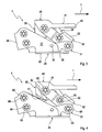
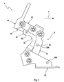
- the enlarged view of the storage 4 shows the particularly compact design of the storage 4 in the folded position.
- the bearing 4 is essentially supported by the bearing block 25 on the vehicle body 21.
- the bearing block 25 is cut from a sheet metal and bent into a substantially U-shaped form, this form consists of two opposite lateral bearing flanges 27 which are supported by means of the integrally connected cross-connection 28 to each other.
- the two lateral flange surfaces 27 are above the flange surface 26 connected.
- the flange surface 26 can consist of two symmetrically folded halves in the center of the bearing block 25 and can be welded together in the area of contact. It is also possible that the flange surface 26 is fixedly connected as a separate part with the lateral flange surfaces 27 via a suitable connection method.
- the main link 31 is also a U-shaped bent sheet metal part, which consists of two side walls and a substantially parallel to the flange 26 of the bearing block 25 aligned transverse connection 36.
- the bearing IV 64 is formed from a received in both lateral bearing flanges 27 in holes and protruding bolts, which is held at each of its ends by means of a locking washer 60 in its position.
- the main link 31 is oriented substantially horizontally.
- the bearing III 63 which is also U-shaped bent from a sheet metal front handlebar 32.
- the storage is formed by a protruding bolt by means of lock washers 60 in the same way.
- the front link 32 is installed with its pointing away from the main link 31 end approximately 45 ° counter to the direction of travel 1 directed backwards above.
- the side walls of the front link 32 are guided within the U-shaped main link 31.
- the side walls of the front link 32 are connected to each other via a cross-link 33 stabilizing.
- the holder 40 is also formed in the storage area U-shaped and stored in the same manner as in the camps IV, III 64, 63.
- the free end of the holder 40 protrudes as a flange 42 in the direction of travel 1, wherein the upwardly facing flange 41 serves for fastening and supporting the cover 2.
- the front handlebar 32nd a vertically downwardly facing stop 50 installed.
- the stop 50 is a flat component, preferably a component made of sheet metal and has at its lower end a curved support surface 51.
- the stopper 50 is mounted together during assembly of the holder 40 on the front handlebar 32.
- the stopper 50 is held over a receiving bore by the bolt of the bearing 61. With its upper end, the stop 50 is supported on the inside of the web of the U-shaped holder 40.
- a rear link 34 via the bearings II, V 62, 65 is installed as a connecting component.
- the rear link 34 is designed angularly and pivotally mounted with its corner within the front arm 32 via the bearing II 62.
- the holder 40 pointing towards the end of the angled rear link 34 can serve as a stop and support for the flange 42 of the holder 40 when folded storage 4.
- the thus formed chain between the bearings IV, III, II, V 64, 63, 62, 65 represents a four-bar linkage 8.
- the gear ratios, the handlebar lengths and bearing arrangements determine both the movement shape, the maximum movement and the speed of movement. Of course, these arrangements can also influence the power support and thus the load on the bearings IV, III, II, V 64, 63, 62, 65 are taken.
- the Fig. 4 shows the storage 4 in slightly open (raised) position.
- the curved support surface 51 of the stopper 50 is slightly raised from the inside of the angled rear link 34.
- the inside of the angle-shaped rear link is correspondingly designed so as to the curved support surface 51 as a receiving surface 52, that when fully folded storage 4 both curved surfaces (support surface 51 and receiving surface 52) completely engage.
- the complete engagement of the support surface 51 and the receiving surface 52 prevents pivoting of the holder 40 and thus also a pivoting of the cover 2.
- the cover 2 over the holder 40, the stop 50 and the rear arm 34 is supported, this arrangement also gives a lock for the cover 2.
- Fig. 5 the storage 4 is shown in fully open position.
- the cover 2 pivoted about the lever mechanism 16 and the coupling rod 15 in its open position, the holder 40 has moved with its flange 42 during the opening operation by about 45 ° from the front handlebar 32 away in an obliquely upward position.
- the stopper 50 comes here with its lower straight portion of the support surface 51 on the end portion of the holder 40 facing part of the rear link 34 in a blocking position, so that the flange 42 attached cover can not independently pivot down.
- a stop pin 53 is provided in the end region of the holder 40 facing the end of the angled rear link 34.
- the lateral walls of the front link 32 are formed cranked in the transverse region of the stop pin 53, so that the rear link 34 can be moved with the stop pin 53 unhindered from the front to the rear position.
- the stopper pin 53 fulfills, inter alia, the function of a lateral guide and support during the opening or closing operation, the ends of the stopper pin 53 can be supported at lateral loads of the bearing 4 on the inner sides of the cranked side walls of the front link 32.
- a locking device could be mounted, which could be extended orthogonal to the rear handlebar 34 at fully open cover 2 and would allow further support or locking to the trailing edge of the front link 32.
- this lock could also engage from outside the storage 4 in an existing instead of the stop pin 53 locking bore.
Landscapes
- Engineering & Computer Science (AREA)
- Mechanical Engineering (AREA)
- Superstructure Of Vehicle (AREA)
- Steering Devices For Bicycles And Motorcycles (AREA)
Applications Claiming Priority (1)
| Application Number | Priority Date | Filing Date | Title |
|---|---|---|---|
| DE102009059651A DE102009059651A1 (de) | 2009-12-19 | 2009-12-19 | Lagerung für eine Abdeckung eines Fahrzeugs |
Publications (2)
| Publication Number | Publication Date |
|---|---|
| EP2338766A1 EP2338766A1 (de) | 2011-06-29 |
| EP2338766B1 true EP2338766B1 (de) | 2012-11-28 |
Family
ID=43747936
Family Applications (1)
| Application Number | Title | Priority Date | Filing Date |
|---|---|---|---|
| EP20100015457 Active EP2338766B1 (de) | 2009-12-19 | 2010-12-09 | Lagerung für eine Abdeckung eines Fahrzeugs |
Country Status (3)
| Country | Link |
|---|---|
| EP (1) | EP2338766B1 (cg-RX-API-DMAC10.html) |
| JP (1) | JP5645639B2 (cg-RX-API-DMAC10.html) |
| DE (1) | DE102009059651A1 (cg-RX-API-DMAC10.html) |
Families Citing this family (2)
| Publication number | Priority date | Publication date | Assignee | Title |
|---|---|---|---|---|
| JP2014108379A (ja) * | 2012-11-30 | 2014-06-12 | Dainippon Printing Co Ltd | セシウム吸着材 |
| KR102854817B1 (ko) * | 2020-07-07 | 2025-09-04 | 현대자동차주식회사 | 차량용 전방 저장장치 |
Family Cites Families (10)
| Publication number | Priority date | Publication date | Assignee | Title |
|---|---|---|---|---|
| JPS56108356A (en) * | 1980-01-31 | 1981-08-27 | Nissan Motor Co Ltd | Lid member opening/closing device |
| JPS6449556U (cg-RX-API-DMAC10.html) * | 1987-09-19 | 1989-03-28 | ||
| JPH03119279A (ja) * | 1989-09-29 | 1991-05-21 | Mazda Motor Corp | 車両の開閉体構造 |
| DE9311798U1 (de) * | 1993-08-07 | 1994-12-08 | Wilhelm Karmann GmbH, 49084 Osnabrück | Versenkbares Faltverdeck für ein Cabriolet-Fahrzeug |
| DE4336278A1 (de) * | 1993-10-23 | 1995-04-27 | Porsche Ag | Betätigungseinrichtung für ein Verdeck und einen Verdeckkastendeckel eines Kraftfahrzeuges |
| DE19912893C2 (de) | 1999-03-23 | 2003-02-27 | Daimler Chrysler Ag | Cabrio-Fahrzeug mit einem Verdeck |
| DE10205227A1 (de) * | 2002-02-08 | 2003-08-21 | Bayerische Motoren Werke Ag | Schwenkverdeck für ein Kraftfahrzeug |
| DE102004023056A1 (de) * | 2004-05-11 | 2005-12-01 | Bayerische Motoren Werke Ag | Klappverdeck für ein Kraftfahrzeug |
| DE102007057545B4 (de) * | 2007-11-29 | 2020-09-17 | Valmet Automotive Oy | Betätigungsvorrichtung für ein Fahrzeug |
| DE102008024980B4 (de) * | 2008-05-23 | 2021-01-07 | Bayerische Motoren Werke Aktiengesellschaft | Schwenklagerung für eine Klappe, insbesondere für eine Verdeckklappe eines Kraftfahrzeugs mit einem Falt- oder Klappverdeck |
-
2009
- 2009-12-19 DE DE102009059651A patent/DE102009059651A1/de not_active Withdrawn
-
2010
- 2010-12-09 EP EP20100015457 patent/EP2338766B1/de active Active
- 2010-12-17 JP JP2010282079A patent/JP5645639B2/ja not_active Expired - Fee Related
Also Published As
| Publication number | Publication date |
|---|---|
| JP2011126524A (ja) | 2011-06-30 |
| EP2338766A1 (de) | 2011-06-29 |
| DE102009059651A1 (de) | 2011-06-22 |
| JP5645639B2 (ja) | 2014-12-24 |
Similar Documents
| Publication | Publication Date | Title |
|---|---|---|
| EP3129275B1 (de) | Heckspoilereinrichtung für ein fahrzeug | |
| DE19538738C1 (de) | Abdeckklappe für eine oberhalb eines Verdecklagers befindliche Durchlaßöffnung in einer Bordwand eines Fahrzeuges | |
| DE19754417C2 (de) | Tür-Scharnier | |
| EP1918146B1 (de) | Cabriolet-Kraftfahrzeug | |
| EP3420167B1 (de) | Stellarmantrieb | |
| DE112011100411B4 (de) | Kraftfahrzeug mit einer schwenkbaren Klappe und mit einer Vorrichtung zum Schließen derselben | |
| EP1897718B1 (de) | Faltverdeck | |
| DE19912893C2 (de) | Cabrio-Fahrzeug mit einem Verdeck | |
| DE102005033599A1 (de) | Verstellvorrichtung eines Verdeckkastendeckels eines Cabriolets | |
| EP1907230B1 (de) | Trägervorrichtung eines verdeckkastendeckels eines cabriolets | |
| DE102005033609B4 (de) | Antriebsvorrichtung eines bewegbaren Bauteils eines Fahrzeugs | |
| EP2338766A1 (de) | Lagerung für eine Abdeckung eines Fahrzeugs | |
| DE10117769B4 (de) | Vorrichtung zur Unterstützung einer Öffnungsbewegung einer Fahrzeugklappe | |
| DE102005033098B4 (de) | Heckklappe für ein Kraftfahrzeug | |
| DE102010018302A1 (de) | Viergelenkscharnier | |
| DE102007018017B3 (de) | Umwandelbares Dach für einen Personenkraftwagen | |
| DE10117767A1 (de) | Heckseitige Abdeckung für ein Cabriolet | |
| EP2338767B1 (de) | Betätigung und Verriegelung für eine Abdeckung eines Fahrzeugs | |
| DE10126454A1 (de) | Fronthaubenanordnung | |
| EP0936131A2 (de) | Kippvorrichtung für abgefederte Fahrerhäuser von Nutzfahrzeugen | |
| EP2357103A2 (de) | Verschluss für eine Verdeckkastendeckel eines Cabriolet-Fahrzeugs | |
| DE102004056657B3 (de) | Antriebsanordnung für ein Fahrzeugteil | |
| DE10353515B3 (de) | Traggestell mit einem Tragrahmen für einen Heckdeckel eines Personenkraftwagens | |
| WO2022013181A1 (de) | Scharnier zur verstellung einer fronthaube von einer normallage in eine schutzlage | |
| EP2383135B1 (de) | Bewegbare Abdeckung |
Legal Events
| Date | Code | Title | Description |
|---|---|---|---|
| PUAI | Public reference made under article 153(3) epc to a published international application that has entered the european phase |
Free format text: ORIGINAL CODE: 0009012 |
|
| AK | Designated contracting states |
Kind code of ref document: A1 Designated state(s): AL AT BE BG CH CY CZ DE DK EE ES FI FR GB GR HR HU IE IS IT LI LT LU LV MC MK MT NL NO PL PT RO RS SE SI SK SM TR |
|
| AX | Request for extension of the european patent |
Extension state: BA ME |
|
| 17P | Request for examination filed |
Effective date: 20111214 |
|
| GRAP | Despatch of communication of intention to grant a patent |
Free format text: ORIGINAL CODE: EPIDOSNIGR1 |
|
| RIC1 | Information provided on ipc code assigned before grant |
Ipc: B60J 5/10 20060101ALI20120524BHEP Ipc: E05B 65/19 20060101ALI20120524BHEP Ipc: B62D 25/10 20060101AFI20120524BHEP |
|
| GRAS | Grant fee paid |
Free format text: ORIGINAL CODE: EPIDOSNIGR3 |
|
| GRAA | (expected) grant |
Free format text: ORIGINAL CODE: 0009210 |
|
| AK | Designated contracting states |
Kind code of ref document: B1 Designated state(s): AL AT BE BG CH CY CZ DE DK EE ES FI FR GB GR HR HU IE IS IT LI LT LU LV MC MK MT NL NO PL PT RO RS SE SI SK SM TR |
|
| REG | Reference to a national code |
Ref country code: GB Ref legal event code: FG4D Free format text: NOT ENGLISH |
|
| REG | Reference to a national code |
Ref country code: DE Ref legal event code: R082 Ref document number: 502010001723 Country of ref document: DE Representative=s name: RAUSCH, GABRIELE, DIPL.-PHYS. DR.RER.NAT., DE Ref country code: CH Ref legal event code: EP |
|
| REG | Reference to a national code |
Ref country code: AT Ref legal event code: REF Ref document number: 586005 Country of ref document: AT Kind code of ref document: T Effective date: 20121215 |
|
| REG | Reference to a national code |
Ref country code: IE Ref legal event code: FG4D Free format text: LANGUAGE OF EP DOCUMENT: GERMAN |
|
| REG | Reference to a national code |
Ref country code: DE Ref legal event code: R096 Ref document number: 502010001723 Country of ref document: DE Effective date: 20130124 |
|
| REG | Reference to a national code |
Ref country code: NL Ref legal event code: VDEP Effective date: 20121128 |
|
| REG | Reference to a national code |
Ref country code: LT Ref legal event code: MG4D |
|
| PG25 | Lapsed in a contracting state [announced via postgrant information from national office to epo] |
Ref country code: SE Free format text: LAPSE BECAUSE OF FAILURE TO SUBMIT A TRANSLATION OF THE DESCRIPTION OR TO PAY THE FEE WITHIN THE PRESCRIBED TIME-LIMIT Effective date: 20121128 Ref country code: ES Free format text: LAPSE BECAUSE OF FAILURE TO SUBMIT A TRANSLATION OF THE DESCRIPTION OR TO PAY THE FEE WITHIN THE PRESCRIBED TIME-LIMIT Effective date: 20130311 Ref country code: NO Free format text: LAPSE BECAUSE OF FAILURE TO SUBMIT A TRANSLATION OF THE DESCRIPTION OR TO PAY THE FEE WITHIN THE PRESCRIBED TIME-LIMIT Effective date: 20130228 Ref country code: LT Free format text: LAPSE BECAUSE OF FAILURE TO SUBMIT A TRANSLATION OF THE DESCRIPTION OR TO PAY THE FEE WITHIN THE PRESCRIBED TIME-LIMIT Effective date: 20121128 Ref country code: FI Free format text: LAPSE BECAUSE OF FAILURE TO SUBMIT A TRANSLATION OF THE DESCRIPTION OR TO PAY THE FEE WITHIN THE PRESCRIBED TIME-LIMIT Effective date: 20121128 |
|
| PG25 | Lapsed in a contracting state [announced via postgrant information from national office to epo] |
Ref country code: GR Free format text: LAPSE BECAUSE OF FAILURE TO SUBMIT A TRANSLATION OF THE DESCRIPTION OR TO PAY THE FEE WITHIN THE PRESCRIBED TIME-LIMIT Effective date: 20130301 Ref country code: SI Free format text: LAPSE BECAUSE OF FAILURE TO SUBMIT A TRANSLATION OF THE DESCRIPTION OR TO PAY THE FEE WITHIN THE PRESCRIBED TIME-LIMIT Effective date: 20121128 Ref country code: PT Free format text: LAPSE BECAUSE OF FAILURE TO SUBMIT A TRANSLATION OF THE DESCRIPTION OR TO PAY THE FEE WITHIN THE PRESCRIBED TIME-LIMIT Effective date: 20130328 Ref country code: PL Free format text: LAPSE BECAUSE OF FAILURE TO SUBMIT A TRANSLATION OF THE DESCRIPTION OR TO PAY THE FEE WITHIN THE PRESCRIBED TIME-LIMIT Effective date: 20121128 Ref country code: LV Free format text: LAPSE BECAUSE OF FAILURE TO SUBMIT A TRANSLATION OF THE DESCRIPTION OR TO PAY THE FEE WITHIN THE PRESCRIBED TIME-LIMIT Effective date: 20121128 |
|
| BERE | Be: lapsed |
Owner name: MAGNA CAR TOP SYSTEMS G.M.B.H. Effective date: 20121231 |
|
| PG25 | Lapsed in a contracting state [announced via postgrant information from national office to epo] |
Ref country code: EE Free format text: LAPSE BECAUSE OF FAILURE TO SUBMIT A TRANSLATION OF THE DESCRIPTION OR TO PAY THE FEE WITHIN THE PRESCRIBED TIME-LIMIT Effective date: 20121128 Ref country code: SK Free format text: LAPSE BECAUSE OF FAILURE TO SUBMIT A TRANSLATION OF THE DESCRIPTION OR TO PAY THE FEE WITHIN THE PRESCRIBED TIME-LIMIT Effective date: 20121128 Ref country code: MC Free format text: LAPSE BECAUSE OF NON-PAYMENT OF DUE FEES Effective date: 20121231 Ref country code: CZ Free format text: LAPSE BECAUSE OF FAILURE TO SUBMIT A TRANSLATION OF THE DESCRIPTION OR TO PAY THE FEE WITHIN THE PRESCRIBED TIME-LIMIT Effective date: 20121128 Ref country code: RS Free format text: LAPSE BECAUSE OF FAILURE TO SUBMIT A TRANSLATION OF THE DESCRIPTION OR TO PAY THE FEE WITHIN THE PRESCRIBED TIME-LIMIT Effective date: 20121128 Ref country code: BG Free format text: LAPSE BECAUSE OF FAILURE TO SUBMIT A TRANSLATION OF THE DESCRIPTION OR TO PAY THE FEE WITHIN THE PRESCRIBED TIME-LIMIT Effective date: 20130228 Ref country code: DK Free format text: LAPSE BECAUSE OF FAILURE TO SUBMIT A TRANSLATION OF THE DESCRIPTION OR TO PAY THE FEE WITHIN THE PRESCRIBED TIME-LIMIT Effective date: 20121128 |
|
| PG25 | Lapsed in a contracting state [announced via postgrant information from national office to epo] |
Ref country code: NL Free format text: LAPSE BECAUSE OF FAILURE TO SUBMIT A TRANSLATION OF THE DESCRIPTION OR TO PAY THE FEE WITHIN THE PRESCRIBED TIME-LIMIT Effective date: 20121128 Ref country code: RO Free format text: LAPSE BECAUSE OF FAILURE TO SUBMIT A TRANSLATION OF THE DESCRIPTION OR TO PAY THE FEE WITHIN THE PRESCRIBED TIME-LIMIT Effective date: 20121128 |
|
| REG | Reference to a national code |
Ref country code: IE Ref legal event code: MM4A |
|
| PG25 | Lapsed in a contracting state [announced via postgrant information from national office to epo] |
Ref country code: BE Free format text: LAPSE BECAUSE OF NON-PAYMENT OF DUE FEES Effective date: 20121231 |
|
| PLBE | No opposition filed within time limit |
Free format text: ORIGINAL CODE: 0009261 |
|
| STAA | Information on the status of an ep patent application or granted ep patent |
Free format text: STATUS: NO OPPOSITION FILED WITHIN TIME LIMIT |
|
| PG25 | Lapsed in a contracting state [announced via postgrant information from national office to epo] |
Ref country code: IE Free format text: LAPSE BECAUSE OF NON-PAYMENT OF DUE FEES Effective date: 20121209 |
|
| 26N | No opposition filed |
Effective date: 20130829 |
|
| PG25 | Lapsed in a contracting state [announced via postgrant information from national office to epo] |
Ref country code: MT Free format text: LAPSE BECAUSE OF FAILURE TO SUBMIT A TRANSLATION OF THE DESCRIPTION OR TO PAY THE FEE WITHIN THE PRESCRIBED TIME-LIMIT Effective date: 20121128 Ref country code: HR Free format text: LAPSE BECAUSE OF FAILURE TO SUBMIT A TRANSLATION OF THE DESCRIPTION OR TO PAY THE FEE WITHIN THE PRESCRIBED TIME-LIMIT Effective date: 20121128 Ref country code: CY Free format text: LAPSE BECAUSE OF FAILURE TO SUBMIT A TRANSLATION OF THE DESCRIPTION OR TO PAY THE FEE WITHIN THE PRESCRIBED TIME-LIMIT Effective date: 20121128 Ref country code: AL Free format text: LAPSE BECAUSE OF FAILURE TO SUBMIT A TRANSLATION OF THE DESCRIPTION OR TO PAY THE FEE WITHIN THE PRESCRIBED TIME-LIMIT Effective date: 20121128 |
|
| REG | Reference to a national code |
Ref country code: DE Ref legal event code: R097 Ref document number: 502010001723 Country of ref document: DE Effective date: 20130829 |
|
| PGFP | Annual fee paid to national office [announced via postgrant information from national office to epo] |
Ref country code: IT Payment date: 20131231 Year of fee payment: 4 |
|
| PG25 | Lapsed in a contracting state [announced via postgrant information from national office to epo] |
Ref country code: TR Free format text: LAPSE BECAUSE OF FAILURE TO SUBMIT A TRANSLATION OF THE DESCRIPTION OR TO PAY THE FEE WITHIN THE PRESCRIBED TIME-LIMIT Effective date: 20121128 |
|
| PG25 | Lapsed in a contracting state [announced via postgrant information from national office to epo] |
Ref country code: LU Free format text: LAPSE BECAUSE OF NON-PAYMENT OF DUE FEES Effective date: 20121209 Ref country code: SM Free format text: LAPSE BECAUSE OF FAILURE TO SUBMIT A TRANSLATION OF THE DESCRIPTION OR TO PAY THE FEE WITHIN THE PRESCRIBED TIME-LIMIT Effective date: 20121128 |
|
| PG25 | Lapsed in a contracting state [announced via postgrant information from national office to epo] |
Ref country code: HU Free format text: LAPSE BECAUSE OF FAILURE TO SUBMIT A TRANSLATION OF THE DESCRIPTION OR TO PAY THE FEE WITHIN THE PRESCRIBED TIME-LIMIT Effective date: 20101209 |
|
| PG25 | Lapsed in a contracting state [announced via postgrant information from national office to epo] |
Ref country code: MK Free format text: LAPSE BECAUSE OF FAILURE TO SUBMIT A TRANSLATION OF THE DESCRIPTION OR TO PAY THE FEE WITHIN THE PRESCRIBED TIME-LIMIT Effective date: 20121128 |
|
| REG | Reference to a national code |
Ref country code: CH Ref legal event code: PL |
|
| PG25 | Lapsed in a contracting state [announced via postgrant information from national office to epo] |
Ref country code: CH Free format text: LAPSE BECAUSE OF NON-PAYMENT OF DUE FEES Effective date: 20141231 Ref country code: LI Free format text: LAPSE BECAUSE OF NON-PAYMENT OF DUE FEES Effective date: 20141231 |
|
| REG | Reference to a national code |
Ref country code: FR Ref legal event code: PLFP Year of fee payment: 6 |
|
| PG25 | Lapsed in a contracting state [announced via postgrant information from national office to epo] |
Ref country code: IT Free format text: LAPSE BECAUSE OF NON-PAYMENT OF DUE FEES Effective date: 20141209 |
|
| PG25 | Lapsed in a contracting state [announced via postgrant information from national office to epo] |
Ref country code: IS Free format text: LAPSE BECAUSE OF FAILURE TO SUBMIT A TRANSLATION OF THE DESCRIPTION OR TO PAY THE FEE WITHIN THE PRESCRIBED TIME-LIMIT Effective date: 20121128 |
|
| REG | Reference to a national code |
Ref country code: FR Ref legal event code: PLFP Year of fee payment: 7 |
|
| REG | Reference to a national code |
Ref country code: AT Ref legal event code: MM01 Ref document number: 586005 Country of ref document: AT Kind code of ref document: T Effective date: 20151209 |
|
| PG25 | Lapsed in a contracting state [announced via postgrant information from national office to epo] |
Ref country code: AT Free format text: LAPSE BECAUSE OF NON-PAYMENT OF DUE FEES Effective date: 20151209 |
|
| REG | Reference to a national code |
Ref country code: FR Ref legal event code: PLFP Year of fee payment: 8 |
|
| REG | Reference to a national code |
Ref country code: DE Ref legal event code: R084 Ref document number: 502010001723 Country of ref document: DE |
|
| REG | Reference to a national code |
Ref country code: DE Ref legal event code: R082 Ref document number: 502010001723 Country of ref document: DE Representative=s name: EULER, MATTHIAS, DR., DE |
|
| PGFP | Annual fee paid to national office [announced via postgrant information from national office to epo] |
Ref country code: DE Payment date: 20251211 Year of fee payment: 16 |
|
| PGFP | Annual fee paid to national office [announced via postgrant information from national office to epo] |
Ref country code: GB Payment date: 20251219 Year of fee payment: 16 |
|
| PGFP | Annual fee paid to national office [announced via postgrant information from national office to epo] |
Ref country code: FR Payment date: 20251222 Year of fee payment: 16 |
|
| REG | Reference to a national code |
Ref country code: DE Ref legal event code: R081 Ref document number: 502010001723 Country of ref document: DE Owner name: A.R. SYSTEMS AUTOMOTIVE GMBH, DE Free format text: FORMER OWNER: MAGNA CAR TOP SYSTEMS GMBH, 74321 BIETIGHEIM-BISSINGEN, DE |