EP2338743A1 - Stossstangeneinheit für Kraftfahrzeug, Kraftfahrzeugendteil mit einer solchen Einheit und Kraftfahrzeug - Google Patents
Stossstangeneinheit für Kraftfahrzeug, Kraftfahrzeugendteil mit einer solchen Einheit und Kraftfahrzeug Download PDFInfo
- Publication number
- EP2338743A1 EP2338743A1 EP10306491A EP10306491A EP2338743A1 EP 2338743 A1 EP2338743 A1 EP 2338743A1 EP 10306491 A EP10306491 A EP 10306491A EP 10306491 A EP10306491 A EP 10306491A EP 2338743 A1 EP2338743 A1 EP 2338743A1
- Authority
- EP
- European Patent Office
- Prior art keywords
- plate
- motor vehicle
- bumper assembly
- longitudinal members
- shield
- Prior art date
- Legal status (The legal status is an assumption and is not a legal conclusion. Google has not performed a legal analysis and makes no representation as to the accuracy of the status listed.)
- Granted
Links
- 239000000463 material Substances 0.000 claims abstract description 8
- 239000004033 plastic Substances 0.000 claims abstract description 5
- 229920003023 plastic Polymers 0.000 claims abstract description 5
- 230000035939 shock Effects 0.000 claims description 20
- 239000002184 metal Substances 0.000 abstract description 7
- 238000001746 injection moulding Methods 0.000 abstract description 2
- 210000002414 leg Anatomy 0.000 description 27
- 230000002787 reinforcement Effects 0.000 description 15
- 230000006835 compression Effects 0.000 description 8
- 238000007906 compression Methods 0.000 description 8
- 238000005452 bending Methods 0.000 description 6
- 238000010521 absorption reaction Methods 0.000 description 5
- 230000008901 benefit Effects 0.000 description 3
- 238000004519 manufacturing process Methods 0.000 description 3
- 230000002829 reductive effect Effects 0.000 description 3
- 239000000243 solution Substances 0.000 description 3
- 239000004743 Polypropylene Substances 0.000 description 2
- 230000000295 complement effect Effects 0.000 description 2
- 238000006073 displacement reaction Methods 0.000 description 2
- 238000009826 distribution Methods 0.000 description 2
- 230000000670 limiting effect Effects 0.000 description 2
- BASFCYQUMIYNBI-UHFFFAOYSA-N platinum Chemical compound [Pt] BASFCYQUMIYNBI-UHFFFAOYSA-N 0.000 description 2
- 229920001155 polypropylene Polymers 0.000 description 2
- 238000004026 adhesive bonding Methods 0.000 description 1
- 238000004378 air conditioning Methods 0.000 description 1
- 230000002238 attenuated effect Effects 0.000 description 1
- 238000001816 cooling Methods 0.000 description 1
- 230000007423 decrease Effects 0.000 description 1
- 230000000694 effects Effects 0.000 description 1
- 230000002349 favourable effect Effects 0.000 description 1
- 239000011888 foil Substances 0.000 description 1
- 230000003116 impacting effect Effects 0.000 description 1
- 210000003127 knee Anatomy 0.000 description 1
- 230000003287 optical effect Effects 0.000 description 1
- 230000021715 photosynthesis, light harvesting Effects 0.000 description 1
- -1 polypropylene Polymers 0.000 description 1
- 230000001681 protective effect Effects 0.000 description 1
- 230000003014 reinforcing effect Effects 0.000 description 1
- 230000000717 retained effect Effects 0.000 description 1
- 238000004513 sizing Methods 0.000 description 1
- 239000000725 suspension Substances 0.000 description 1
- 210000002303 tibia Anatomy 0.000 description 1
- 230000003313 weakening effect Effects 0.000 description 1
Images


Classifications
-
- B—PERFORMING OPERATIONS; TRANSPORTING
- B60—VEHICLES IN GENERAL
- B60R—VEHICLES, VEHICLE FITTINGS, OR VEHICLE PARTS, NOT OTHERWISE PROVIDED FOR
- B60R19/00—Wheel guards; Radiator guards, e.g. grilles; Obstruction removers; Fittings damping bouncing force in collisions
- B60R19/02—Bumpers, i.e. impact receiving or absorbing members for protecting vehicles or fending off blows from other vehicles or objects
- B60R19/24—Arrangements for mounting bumpers on vehicles
- B60R19/26—Arrangements for mounting bumpers on vehicles comprising yieldable mounting means
- B60R19/34—Arrangements for mounting bumpers on vehicles comprising yieldable mounting means destroyed upon impact, e.g. one-shot type
-
- B—PERFORMING OPERATIONS; TRANSPORTING
- B60—VEHICLES IN GENERAL
- B60R—VEHICLES, VEHICLE FITTINGS, OR VEHICLE PARTS, NOT OTHERWISE PROVIDED FOR
- B60R19/00—Wheel guards; Radiator guards, e.g. grilles; Obstruction removers; Fittings damping bouncing force in collisions
- B60R19/02—Bumpers, i.e. impact receiving or absorbing members for protecting vehicles or fending off blows from other vehicles or objects
- B60R19/04—Bumpers, i.e. impact receiving or absorbing members for protecting vehicles or fending off blows from other vehicles or objects formed from more than one section in a side-by-side arrangement
- B60R19/12—Bumpers, i.e. impact receiving or absorbing members for protecting vehicles or fending off blows from other vehicles or objects formed from more than one section in a side-by-side arrangement vertically spaced
-
- B—PERFORMING OPERATIONS; TRANSPORTING
- B60—VEHICLES IN GENERAL
- B60R—VEHICLES, VEHICLE FITTINGS, OR VEHICLE PARTS, NOT OTHERWISE PROVIDED FOR
- B60R19/00—Wheel guards; Radiator guards, e.g. grilles; Obstruction removers; Fittings damping bouncing force in collisions
- B60R19/02—Bumpers, i.e. impact receiving or absorbing members for protecting vehicles or fending off blows from other vehicles or objects
- B60R19/24—Arrangements for mounting bumpers on vehicles
-
- B—PERFORMING OPERATIONS; TRANSPORTING
- B62—LAND VEHICLES FOR TRAVELLING OTHERWISE THAN ON RAILS
- B62D—MOTOR VEHICLES; TRAILERS
- B62D21/00—Understructures, i.e. chassis frame on which a vehicle body may be mounted
- B62D21/15—Understructures, i.e. chassis frame on which a vehicle body may be mounted having impact absorbing means, e.g. a frame designed to permanently or temporarily change shape or dimension upon impact with another body
- B62D21/152—Front or rear frames
-
- B—PERFORMING OPERATIONS; TRANSPORTING
- B62—LAND VEHICLES FOR TRAVELLING OTHERWISE THAN ON RAILS
- B62D—MOTOR VEHICLES; TRAILERS
- B62D25/00—Superstructure or monocoque structure sub-units; Parts or details thereof not otherwise provided for
- B62D25/08—Front or rear portions
- B62D25/082—Engine compartments
- B62D25/084—Radiator supports
-
- B—PERFORMING OPERATIONS; TRANSPORTING
- B60—VEHICLES IN GENERAL
- B60R—VEHICLES, VEHICLE FITTINGS, OR VEHICLE PARTS, NOT OTHERWISE PROVIDED FOR
- B60R19/00—Wheel guards; Radiator guards, e.g. grilles; Obstruction removers; Fittings damping bouncing force in collisions
- B60R19/02—Bumpers, i.e. impact receiving or absorbing members for protecting vehicles or fending off blows from other vehicles or objects
- B60R19/18—Bumpers, i.e. impact receiving or absorbing members for protecting vehicles or fending off blows from other vehicles or objects characterised by the cross-section; Means within the bumper to absorb impact
- B60R2019/186—Additional energy absorbing means supported on bumber beams, e.g. cellular structures or material
-
- B—PERFORMING OPERATIONS; TRANSPORTING
- B60—VEHICLES IN GENERAL
- B60R—VEHICLES, VEHICLE FITTINGS, OR VEHICLE PARTS, NOT OTHERWISE PROVIDED FOR
- B60R21/00—Arrangements or fittings on vehicles for protecting or preventing injuries to occupants or pedestrians in case of accidents or other traffic risks
- B60R21/34—Protecting non-occupants of a vehicle, e.g. pedestrians
- B60R2021/343—Protecting non-occupants of a vehicle, e.g. pedestrians using deformable body panel, bodywork or components
Definitions
- the present invention relates to a motor vehicle bumper assembly having a structure comprising a pair of upper spars and a pair of lower spars, the bumper assembly being of the type comprising an energy absorbing shield having at least two jambs each provided to bear on the ends of an upper spar and a lower spar and a beam extending transversely between the legs.
- Modern motor vehicles are designed to respond appropriately to different types of possible frontal shocks, such as low-speed shocks or parking shocks for speeds between 2.5 and 4 km / h (ECE 42), shocks to medium speed or "reparability shocks", for a speed of about 16 km / h (DANNER shocks) and high speed shocks, for a speed between 56 and 65 km / h.
- frontal shocks such as low-speed shocks or parking shocks for speeds between 2.5 and 4 km / h (ECE 42), shocks to medium speed or "reparability shocks", for a speed of about 16 km / h (DANNER shocks) and high speed shocks, for a speed between 56 and 65 km / h.
- Modern motor vehicles are also designed to protect pedestrians in case of pedestrian shocks and in particular to protect the pedestrian's legs and hip.
- An object of the invention is to provide a bumper assembly for suitably absorbing the energy of a shock by limiting the intrusion of an object colliding with the vehicle towards the interior of the structure of the vehicle. vehicle.
- the invention proposes a bumper assembly of the aforementioned type, characterized in that it comprises a plate doubling the beam so that the beam is pressed against a front face of the plate in case of impact.
- the invention also relates to a motor vehicle end portion comprising a pair of upper spars and a pair of lower spars and a bumper assembly as defined above disposed at the ends of the upper and lower spars, the plate s' extending transversely between the longitudinal members by being connected thereto.
- the invention also relates to a motor vehicle comprising an end portion as defined above.
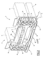
- a motor vehicle 2 (partially shown) comprises a front portion 4 having a pair of upper spars 6, a pair of lower spars 8 and a front bumper assembly 10.
- the upper longitudinal members 6 extend substantially in the longitudinal direction of the motor vehicle and are spaced transversely from one another.
- the lower rails 8 extend substantially in the longitudinal direction of the motor vehicle and are spaced transversely from one another.
- the transverse spacing between the lower spars 8 is substantially equal to the transverse spacing between the upper spars 6.
- the lower spars 8 are located at a height lower than those of the upper spars 6.
- Each lower spar 8 extends under a spar 6 substantially in the same vertical and longitudinal plane.
- the ends of the upper spars 6 and lower spars 8 are substantially in the same vertical and transverse plane.
- the upper longitudinal members 6 are typically calibrated to accommodate a maximum axial force without buckling of between 80 kN and 100 kN.
- the lower longitudinal members 8 are typically calibrated to accommodate a maximum axial force without buckling of between 25 kN and 45 kN.
- the rating ranges proposed may differ slightly without departing from the scope of the invention.
- the upper rails 6 are provided to receive between them and support at least partly a front face.
- a front face is conventionally in the form of a frame carrying functional bodies of the motor vehicle such as a radiator of a cooling system of the powertrain and / or such as one or more radiators or a fan motor group. an air conditioning system such.
- the front face is fixed to the upper spar 6, preferably recessed from the ends of the upper spars 6.
- the bumper assembly 10 comprises a shield 12 of energy absorption and a reinforcement 14 at least partially doubling the shield 12.
- the shield 12 is provided to dissipate energy by deforming, and in particular by crashing or compressing in the longitudinal direction, under the effect of a shock.
- the shield 12 is in the form of a block of material having a thickness in the longitudinal direction, between a front face 12a and a rear face 12b of the shield 12.
- the shield 12 has in this thickness a box structure for a significant dissipation of energy.
- the shield 12 comprises two legs 16 and an upper beam 18 extending transversely between the legs 16. Each leg 16 is provided to extend substantially vertically, the upper beam 18 extending substantially horizontally between the legs 16. Each leg 16 is provided to come rigidly against the ends of an upper spar 6 and a spar at the same time lower than 8 adjacent on the same side ( figure 2 ). Upper beam 18 and jambs 16 together define an inverted "H" or "U” shape. The upper beam 18 is substantially at the height of the upper longitudinal members 6.
- the shield 12 comprises a lower beam 20 extending transversely between the lower ends of the legs 16.
- the lower beam 20 is spaced vertically from the upper beam 18.
- the shield 12 provided with the lower beam 20 has a general shape of rectangular frame.
- the lower beam 18 is located substantially at the height of the lower longitudinal members 8.
- the legs 16 have the function of absorbing energy by compression in case of shock.
- Each leg 16 has for this purpose a certain thickness and has a box structure.
- each leg 16 has a honeycomb structure comprising cells extending longitudinally between the front face 12a and a rear face 12b of the shield 12.
- Each leg 16 comprises inverted cells comprising first cells 22 closed on the side of the rear face 12b and open on the side of the front face 12a and second cells 24 open on the side of the rear face and closed on the side of the front face.
- the first cells 22 and the second cells 24 are arranged staggered (or checkered).
- the walls closing the cells 22, 24 are provided with weakening orifices 26 to obtain a satisfactory dissipation of energy.
- the walls closing the cells 22, 24 are full.
- the upper beam 18 also has the function of absorbing energy by compression in case of shock.
- the upper beam 18 has a certain thickness and has a box structure.
- the upper beam 18 has a substantially W-shaped cross-section defining two channels open towards the rear and a channel open towards the front, and reinforcement ribs 28 ( figures 1 and 2 ) extending inside the channels.
- the lower beam 20 serves to protect the legs of a pedestrian in case of shocks.
- the lower beam 20 is intended to impact the leg of a pedestrian at the tibia, below the knee.
- the lower beam 20 is designed to work essentially in flexion when it is shocked.
- the lower beam 20 is arched towards forward. It has a rearward open U-shaped cross-section and internal reinforcing ribs ( figure 3 ).
- the shield 12 further comprises pedestrian protection ribs 32 projecting horizontally forwardly from the lower beam 20 and the legs 16, substantially at the height of the lower beam 20.
- These protective ribs 32 form an area of first contact with the leg of a pedestrian. They are intended to flambé under a weak effort.
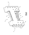
- the reinforcement 14 is in the form of a thin sheet at least partially doubling the shield 12 and provided to provide a rigid support to the shield 12 for compressive compression against the reinforcement 14 in case of impact.
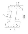
- the reinforcement 14 comprises plates 34 spaced transversely and a plate 36 extending transversely between the plates 34.
- the plate 36 is provided for doubling the upper beam 18.
- Each plate 34 is provided to double a respective leg 16.
- the plates 34 and the plate 36 give the reinforcement 14 an inverted "H" or "U" shape.
- the reinforcement 14 is designed to be arranged against the rear face 12b of the shield 12, sandwiched between the shield 12 and the ends of the longitudinal members 6, 8.
- Each plate 34 is fixed to the ends of an upper spar 6 and an adjacent lower spar 8, sandwiched between said ends and a jamb 16. Each plate 34 makes a connection between the upper spar 6 and the lower spar 8 adjacent. Each plate 34 has a front face 34a of support for a jamb 16.
- the plate 36 extends transversely between the longitudinal members 6, 8, substantially at the height of the upper longitudinal members 6.
- the plate 36 connects the upper longitudinal members 6 between them.
- the plate 36 has a front face 36a of support for the upper beam 18.
- the plate 36 is in the form of a thin sheet having a flexural rigidity in the weak longitudinal direction.
- the plate 36 is relatively flexible in the longitudinal direction in the free state and linked at its ends to the upper longitudinal members 6.
- the plate 36 can have bending strength and works essentially in tension between the two upper longitudinal members 6 which hold the plate 36 at its ends.
- the upper beam 18 operates in a complementary manner with the plate 36.
- the plate 36 although being relatively flexible in the longitudinal direction, and retained because of its connection to the upper longitudinal members 6 and provides a transversely extended support surface for the upper beam 18 allowing the upper beam 18 to work uniformly in compression against the plate 36 in case of shock.
- the energy is dissipated over a small stroke, for example corresponding to the thickness of the upper beam 18 and for example between 100 and 180 mm.
- This operation with separate functions - compression of the upper beam 18 and traction of the plate 36 - allows efficient and controlled work of the assembly formed by the upper beam 18 and the plate 36.
- the plate 36 may be provided in a tensile-resistant material, for example a metal sheet, while the upper beam 18 is provided in a material allowing a large energy dissipation by compression, for example a plastic material such as polypropylene (PP).
- PP polypropylene
- the elongation of the plate 36 provided in the form of a metal foil can be reduced (between 2% and 8%) which makes it possible to limit the intrusion of another vehicle or of an object struck by the assembly. bumper 10 inwardly of the motor vehicle 2 and maintain an effective connection between the two upper longitudinal members 6.
- the plates 34 high or "giant plates” connecting each upper spar 6 to a lower spar 8 can distribute the efforts received by the entire bumper 10 to a high height in the vehicle.
- the plates 34 provide a rigid support surface extended to the legs 16, which allows the legs 16 to work uniformly in compression in case of shocks, without bending in their median portion located vertically between the upper rails 6 and the lower longitudinal members 8. This advantage allows a homogeneous design of jambs 16 having similar cells uniformly distributed.
- each plate 34 The dimensions of the support offered by each plate 34 are advantageously between 100 and 190 mm in width and between 350 and 400 mm in height, which corresponds to areas generally between 3, 5 and 8 dm 2 .
- the shield 12 and the reinforcement 14 operate in a complementary manner in the event of impact.
- the shield 12 thick compresses by dissipating energy, while the thin reinforcement 14 distributes the forces on the longitudinal members 6, 8 and provides support for the upper beam 18 without compressing and retaining its mechanical strength in traction.
- the bumper assembly 10 is designed to absorb the energy in the event of low speed or medium speed impact, so as to preserve the integrity of the longitudinal members 6, 8.
- the vehicle equipped with a bumper assembly according to the invention is less intrusive when it comes into contact with another vehicle, which benefits inter-vehicular compatibility at low and medium speed.
- the honeycomb structure of the legs 16 facilitates the manufacture and confers a sufficient capacity of absorption of the energy on a low thickness.
- the shield 12 is advantageously obtained as a single unit, for example by plastic injection molding. It can be demolded in a single direction corresponding to the longitudinal direction of the motor vehicle when the shield 12 is fixed on the longitudinal members 6. Thus, the shield 12 can be obtained in a simple manner, with a low manufacturing cost.
- the shield 12 comprises a lower beam 20 integral with the legs 16 and the upper beam 18.
- the shield 12 has no lower beam. It is also possible to provide a lower beam separated from the shield 12 is reported between the lower ends of the legs 16.
- the honeycomb structure of the legs 16 allows low or even no remains, which limits the weight, and the cost of manufacturing the shield 12.
- the parts obtained are therefore light and have a saving in material.
- the honeycomb structure of the jambs 16 also makes it possible to reduce the local thicknesses of walls delimiting the cells.
- this local thickness can be reduced in a range between 2.5 and 4 mm, advantageously between 3 mm and 3.5 mm.
- the demolding of the one-piece shield 12 is facilitated since the small remains and their absence allows demolding by movement of two opposing half-molds in opposite directions along an axis corresponding to the longitudinal axis of the motor vehicle. Thus it is not necessary to provide drawers or moving parts in the mold.
- the low or no remains in the jambs 16 checkerboard to obtain a uniform stiffness during a depression or crushing, for example during a shock at medium speed.
- the energy of a shock can be dissipated with a reduced stroke and the solution is very compact.
- This solution is therefore particularly suitable for low-displacement vehicles having a longitudinal shock absorption of less than 250 mm, and in particular less than 200 mm.
- the legs 16 have a longitudinal thickness of between 220 and 220 mm. This allows efficient energy absorption while limiting the overhang of the shield 12 taken between the plates 14 and the front end of the shield 12.
- the reinforcement 14 is advantageously made in one piece and formed from a side sheet metal cut and if necessary shaped, in particular by stamping and / or folding. Thus, the reinforcement 14 is easily obtained at low cost and has a high resistance.
- the reinforcement 14 is formed by fixing metal flanks between them, for example two flanks defining the plates 34 and a flank defining the plate 36.
- Each leg 16 is fixed on the corresponding plate 34 by screwing or gluing.
- This second solution is advantageous, insofar as it allows a good distribution of efforts. Indeed, the constraints of design and assembly by screwing (metal insert, hole, stiffening sole, space for screwdrivers) are lifted while the localized stresses and the risks of tearing caused by the screwing are very strongly attenuated .
- the chosen geometry formed of inverted closed cells arranged in staggered rows considerably increases the sizing area at the rear of the uprights and contributes to the favorable distribution of the forces.
- the reinforcement 14 comprises a substantially plane plate 36 coplanar with the plates 34.
- the plate 36 has a flat central portion 39 offset from the plate 34 to follow the rear face 12b of the shield 12 along the upper beam 18 and the curved lateral portions 40 connecting the plate 36 to the plates 34.
- Plate 36 of the figure 5 has a rectilinear cross section along its entire length and retains a weak bending moment in the longitudinal direction.
- the upper and lower side edges 42 of the plate 34 are flat.
- the plate 34 is flat but provided with lateral edges 42 raised or " fallen” to limit the risk of occurrence of cracks on the edges 42 of the plate 36. Nevertheless, the raised side edges have a low height so that the plate 36 retains a weak bending moment in the direction perpendicular to its front face 36a. To limit the bending moment of the plate 36, the lateral edges 42 are advantageously folded down.
- the lateral edges 42 fallen and / or folded extend in cross-sectional view over a length of between 5 mm and 10 mm.
- the plate is provided at any point along its length with a cross-section giving it a low bending rigidity in the longitudinal direction, so that the plate is relatively flexible in the longitudinal direction in the free state, but that because of its connection to the upper spars, it works mainly in traction between the upper longitudinal members in case of impact and offers a relatively rigid support for the beam that works mainly in compression.
- the upper longitudinal members 6 are preferably the main longitudinal members of the structure of the motor vehicle.
- the lower longitudinal members 8 are in one embodiment of the lower longitudinal members of the structure of the motor vehicle provided for example in the form of extensions extending from the lower longitudinal members 6 away from the ends of the latter.
- the lower rails 8 are extensions of a cradle or auxiliary frame fixed under the structure of the motor vehicle.
- the cradle can support other equipment of the motor vehicle such as suspension arms, an anti-roll bar and / or a steering system. It can support at least part of an engine, in which case it can be called "cradle engine”.
- the shield 12 may carry additional optical blocks (not shown), unrepresented elements for fixing panels of the skin of the shield, the fastening elements not shown a shell, piloted flaps assembled behind the shell to channel the flows of air.
- the invention applies to the front parts of motor vehicles as well as the rear parts of motor vehicles, and, in general, to the end parts of motor vehicles.
Priority Applications (1)
| Application Number | Priority Date | Filing Date | Title |
|---|---|---|---|
| SI201030687T SI2338743T1 (sl) | 2009-12-24 | 2010-12-22 | Sklop odbijača za motorna vozila, končni del motornega vozila, obsegajoč tovrsten sklop ter motorno vozilo |
Applications Claiming Priority (1)
| Application Number | Priority Date | Filing Date | Title |
|---|---|---|---|
| FR0959606A FR2954738B1 (fr) | 2009-12-24 | 2009-12-24 | Ensemble pare-chocs pour vehicule automobile, partie d'extremite de vehicule automobile comprenant un tel ensemble et vehicule automobile |
Publications (2)
| Publication Number | Publication Date |
|---|---|
| EP2338743A1 true EP2338743A1 (de) | 2011-06-29 |
| EP2338743B1 EP2338743B1 (de) | 2014-07-16 |
Family
ID=42315570
Family Applications (1)
| Application Number | Title | Priority Date | Filing Date |
|---|---|---|---|
| EP10306491.1A Not-in-force EP2338743B1 (de) | 2009-12-24 | 2010-12-22 | Stossstangeneinheit für Kraftfahrzeug, Kraftfahrzeugendteil mit einer solchen Einheit und Kraftfahrzeug |
Country Status (8)
| Country | Link |
|---|---|
| US (1) | US8562042B2 (de) |
| EP (1) | EP2338743B1 (de) |
| KR (1) | KR101745382B1 (de) |
| CN (1) | CN102180134B (de) |
| ES (1) | ES2502532T3 (de) |
| FR (1) | FR2954738B1 (de) |
| MX (1) | MX2011000107A (de) |
| SI (1) | SI2338743T1 (de) |
Cited By (1)
| Publication number | Priority date | Publication date | Assignee | Title |
|---|---|---|---|---|
| FR3012103A3 (fr) * | 2013-10-22 | 2015-04-24 | Renault Sa | Ensemble de voie avant de vehicule automobile |
Families Citing this family (16)
| Publication number | Priority date | Publication date | Assignee | Title |
|---|---|---|---|---|
| FR2943595B1 (fr) * | 2009-03-26 | 2011-06-03 | Faurecia Bloc Avant | Ensemble avant de vehicule automobile comprenant un bouclier pare-chocs avant |
| DE102009052110A1 (de) * | 2009-11-05 | 2011-05-12 | Faurecia Innenraum Systeme Gmbh | Kraftfahrzeug-Frontend |
| DE102010006978A1 (de) * | 2010-02-05 | 2011-08-11 | GM Global Technology Operations LLC, ( n. d. Ges. d. Staates Delaware ), Mich. | Stoßfängeranordnung für ein Kraftfahrzeug |
| DE102010006976A1 (de) * | 2010-02-05 | 2011-08-11 | GM Global Technology Operations LLC, ( n. d. Ges. d. Staates Delaware ), Mich. | Kraftfahrzeug-Vorderbau |
| FR2959707B1 (fr) * | 2010-05-05 | 2013-03-15 | Faurecia Bloc Avant | Element de face arriere et face arriere pour vehicule automobile |
| JP5516345B2 (ja) * | 2010-11-11 | 2014-06-11 | マツダ株式会社 | 車両用フレーム構造 |
| US8746762B2 (en) | 2012-06-04 | 2014-06-10 | Steven Darrett | Car door shock absorber |
| CN105073562B (zh) * | 2013-04-04 | 2018-07-27 | 丰田自动车株式会社 | 车身端部结构 |
| JP5850037B2 (ja) * | 2013-12-24 | 2016-02-03 | トヨタ自動車株式会社 | 車体の衝撃吸収構造 |
| DE102014214561A1 (de) * | 2014-07-24 | 2016-01-28 | Magna Exteriors Gmbh | Frontendmodul |
| DE102015005925A1 (de) * | 2015-05-07 | 2016-11-10 | Daimler Ag | Frontendträger für einen Personenkraftwagen |
| CN105946758A (zh) * | 2016-06-15 | 2016-09-21 | 苏州市振业模具有限公司 | 一种紧固型保险杠支架 |
| US10106197B2 (en) * | 2017-03-07 | 2018-10-23 | Ford Global Technologies, Llc | Device and assembly for protecting a front end module of a motor vehicle |
| JP6852956B2 (ja) * | 2018-11-27 | 2021-03-31 | ダイハツ工業株式会社 | 車両前部構造 |
| FR3093047B1 (fr) * | 2019-02-27 | 2022-06-10 | Psa Automobiles Sa | Élément absorbeur de chocs pour une structure avant de véhicule automobile |
| EP3718830B1 (de) * | 2019-04-01 | 2022-10-12 | Volvo Car Corporation | Einteilige lastverteilungsvorrichtung |
Citations (5)
| Publication number | Priority date | Publication date | Assignee | Title |
|---|---|---|---|---|
| FR2882327A1 (fr) * | 2005-02-21 | 2006-08-25 | Renault Sas | Structure avant de vehicule automobile |
| FR2911559A1 (fr) * | 2007-01-23 | 2008-07-25 | Plastic Omnium Cie | Module d'absorption de chocs pour vehicule automobile. |
| FR2919568A1 (fr) * | 2007-08-03 | 2009-02-06 | Faurecia Bloc Avant | Face avant de vehicule automobile avec une poutre rigide interposee entre les absorbeurs de chocs et les longerons principaux |
| EP2135775A1 (de) * | 2008-06-18 | 2009-12-23 | Faurecia Bloc Avant | Stoßstangenanordnung und entsprechendes Kraftfahrzeug |
| DE202010002511U1 (de) * | 2009-03-26 | 2010-05-06 | Faurecia Kunststoffe Automobilsysteme Gmbh | Fronteinheit eines Automobilfahrzeugs mit einem vorderen Stoßfänger-Schutzschild |
Family Cites Families (11)
| Publication number | Priority date | Publication date | Assignee | Title |
|---|---|---|---|---|
| US3819224A (en) * | 1973-05-10 | 1974-06-25 | Gen Motors Corp | Vehicle body construction |
| US4951985A (en) * | 1988-11-01 | 1990-08-28 | Transitions Research Corporation | Bumper for impact detection |
| DE19851495A1 (de) * | 1998-11-09 | 2000-05-11 | Volkswagen Ag | Tragstruktur eines Vorderwagens eines Kraftfahrzeugs |
| JP4576780B2 (ja) * | 2001-09-21 | 2010-11-10 | マツダ株式会社 | 車体のフレーム構造及び車体フレームの製造方法 |
| US6685243B1 (en) * | 2002-07-30 | 2004-02-03 | Shape Corporation | Bumper for reducing pedestrian injury |
| CA2567253A1 (en) * | 2004-05-18 | 2005-11-24 | Silverbrook Research Pty Ltd | Pharmaceutical product tracking |
| FR2895341B1 (fr) * | 2005-12-23 | 2008-04-04 | Plastic Omnium Cie | Systeme d'absorption d'energie pour un vehicule automobile |
| DE102006060650A1 (de) | 2006-12-21 | 2008-06-26 | Mtu Aero Engines Gmbh | Vorrichtung und Verfahren zur berührungslosen Schaufelschwingungsmessung |
| FR2910865B1 (fr) * | 2006-12-28 | 2009-04-03 | Plastic Omnium Cie | Piece d'appui pour systeme d'absorption de chocs destinee a etre montee en bout d'un longeron d'un vehicule automobile |
| FR2952875B1 (fr) * | 2009-11-20 | 2012-05-11 | Faurecia Bloc Avant | Bouclier pare-chocs pour vehicule automobile |
| US8439411B2 (en) * | 2010-04-09 | 2013-05-14 | Magna International Inc. | Bumper beam with integrated energy absorber |
-
2009
- 2009-12-24 FR FR0959606A patent/FR2954738B1/fr not_active Expired - Fee Related
-
2010
- 2010-12-22 ES ES10306491.1T patent/ES2502532T3/es active Active
- 2010-12-22 EP EP10306491.1A patent/EP2338743B1/de not_active Not-in-force
- 2010-12-22 SI SI201030687T patent/SI2338743T1/sl unknown
- 2010-12-23 US US12/977,539 patent/US8562042B2/en active Active
- 2010-12-24 KR KR1020100134941A patent/KR101745382B1/ko active IP Right Grant
- 2010-12-24 CN CN201010625271.8A patent/CN102180134B/zh not_active Expired - Fee Related
-
2011
- 2011-01-05 MX MX2011000107A patent/MX2011000107A/es active IP Right Grant
Patent Citations (5)
| Publication number | Priority date | Publication date | Assignee | Title |
|---|---|---|---|---|
| FR2882327A1 (fr) * | 2005-02-21 | 2006-08-25 | Renault Sas | Structure avant de vehicule automobile |
| FR2911559A1 (fr) * | 2007-01-23 | 2008-07-25 | Plastic Omnium Cie | Module d'absorption de chocs pour vehicule automobile. |
| FR2919568A1 (fr) * | 2007-08-03 | 2009-02-06 | Faurecia Bloc Avant | Face avant de vehicule automobile avec une poutre rigide interposee entre les absorbeurs de chocs et les longerons principaux |
| EP2135775A1 (de) * | 2008-06-18 | 2009-12-23 | Faurecia Bloc Avant | Stoßstangenanordnung und entsprechendes Kraftfahrzeug |
| DE202010002511U1 (de) * | 2009-03-26 | 2010-05-06 | Faurecia Kunststoffe Automobilsysteme Gmbh | Fronteinheit eines Automobilfahrzeugs mit einem vorderen Stoßfänger-Schutzschild |
Cited By (1)
| Publication number | Priority date | Publication date | Assignee | Title |
|---|---|---|---|---|
| FR3012103A3 (fr) * | 2013-10-22 | 2015-04-24 | Renault Sa | Ensemble de voie avant de vehicule automobile |
Also Published As
| Publication number | Publication date |
|---|---|
| FR2954738A1 (fr) | 2011-07-01 |
| CN102180134A (zh) | 2011-09-14 |
| FR2954738B1 (fr) | 2012-04-06 |
| KR101745382B1 (ko) | 2017-06-09 |
| KR20110074483A (ko) | 2011-06-30 |
| US8562042B2 (en) | 2013-10-22 |
| EP2338743B1 (de) | 2014-07-16 |
| MX2011000107A (es) | 2011-06-24 |
| ES2502532T3 (es) | 2014-10-03 |
| US20110156414A1 (en) | 2011-06-30 |
| SI2338743T1 (sl) | 2014-12-31 |
| CN102180134B (zh) | 2016-08-03 |
Similar Documents
| Publication | Publication Date | Title |
|---|---|---|
| EP2338743B1 (de) | Stossstangeneinheit für Kraftfahrzeug, Kraftfahrzeugendteil mit einer solchen Einheit und Kraftfahrzeug | |
| EP2233368B1 (de) | Frontteil eines Kraftfahrzeuges, dass eine Frontstossstangenabdeckung umfasst | |
| EP2325057B1 (de) | Stossstangenstruktur für Kraftfahrzeug | |
| EP2135775B1 (de) | Stoßstangenanordnung und entsprechendes Kraftfahrzeug | |
| EP2322386B1 (de) | Vorderwagenstruktur für ein Kraftfahrzeug mit einem vorderen Stossfänger mit Befestigungseinrichtungen zumindest einer zusätzlichen Ausrüstung des Kraftfahrzeugs | |
| EP2384938B1 (de) | Heck für ein Kraftfahrzeug | |
| FR2708553A1 (fr) | Véhicule automobile à structure de plancher rigide. | |
| WO2006136745A2 (fr) | Poutre d'absorption d'energie, notamment pour vehicule automobile, et vehicule automobile equipe d'une telle poutre | |
| EP2241480B1 (de) | Kraftfahrzeugvorderbau mit grossem Stossstangestützplatinen | |
| EP2135776A1 (de) | Hintere Stoßstange für Nutzfahrzeug | |
| EP1693283B1 (de) | Vorderbau für ein Kraftfahrzeug | |
| EP2325056B1 (de) | Verformbarer Stoßfänger für Kraftfahrzeug | |
| EP1473197B1 (de) | Kraftfahrzeug-Stossfänger mit energieabsorbierenden Elementen, und mit einem solchen Stossfänger ausgerüstetes Kraftfahrzeug | |
| FR2980145A1 (fr) | Poutre de pare-chocs, ensemble pare-chocs et vehicule equipes d'une telle poutre de pare-chocs | |
| EP2325070B1 (de) | Frontendmodul eines Kraftfahrzeugs, das einen verformbaren vorderen Stoßfänger umfasst, der mit einem Träger zur Befestigung einer Hilfsausrüstung des Kraftfahrzeugs ausgestattet ist | |
| EP1930230A1 (de) | Fahrzeug mit Kühlerkassette, die mit mindestens einem Element zur Absorption eines Frontalzusammenstoßes ausgestattet ist | |
| EP2251232A1 (de) | Vordere Stoßfängerstruktur eines Kraftfahrzeugs, die quer verteilte Elemente zur Absorption umfasst | |
| FR3012103A3 (fr) | Ensemble de voie avant de vehicule automobile | |
| EP3199409B1 (de) | Formelement eines belüftungsgitters für die frontseite eines kraftfahrzeugs | |
| FR2882327A1 (fr) | Structure avant de vehicule automobile | |
| EP1652732B1 (de) | Stromlinienförmige Vorrichtung für einen Stossfänger für ein Kraftfahrzeug | |
| FR3040034A1 (fr) | Traverse inferieure de baie de vehicule automobile | |
| FR2963299A1 (fr) | Ensemble poutre transversale avant pour vehicule automobile et bloc d'absorption de choc frontal et vehicule automobile equipe d'un tel ensemble | |
| FR2934823A1 (fr) | Face avant avec au moins quatre traverses | |
| FR2913940A1 (fr) | Carenage de protection moteur renforce pour vehicule |
Legal Events
| Date | Code | Title | Description |
|---|---|---|---|
| PUAI | Public reference made under article 153(3) epc to a published international application that has entered the european phase |
Free format text: ORIGINAL CODE: 0009012 |
|
| AK | Designated contracting states |
Kind code of ref document: A1 Designated state(s): AL AT BE BG CH CY CZ DE DK EE ES FI FR GB GR HR HU IE IS IT LI LT LU LV MC MK MT NL NO PL PT RO RS SE SI SK SM TR |
|
| AX | Request for extension of the european patent |
Extension state: BA ME |
|
| 17P | Request for examination filed |
Effective date: 20110826 |
|
| 17Q | First examination report despatched |
Effective date: 20130301 |
|
| GRAP | Despatch of communication of intention to grant a patent |
Free format text: ORIGINAL CODE: EPIDOSNIGR1 |
|
| INTG | Intention to grant announced |
Effective date: 20140218 |
|
| GRAS | Grant fee paid |
Free format text: ORIGINAL CODE: EPIDOSNIGR3 |
|
| GRAA | (expected) grant |
Free format text: ORIGINAL CODE: 0009210 |
|
| AK | Designated contracting states |
Kind code of ref document: B1 Designated state(s): AL AT BE BG CH CY CZ DE DK EE ES FI FR GB GR HR HU IE IS IT LI LT LU LV MC MK MT NL NO PL PT RO RS SE SI SK SM TR |
|
| REG | Reference to a national code |
Ref country code: GB Ref legal event code: FG4D Free format text: NOT ENGLISH |
|
| REG | Reference to a national code |
Ref country code: CH Ref legal event code: EP |
|
| REG | Reference to a national code |
Ref country code: IE Ref legal event code: FG4D Free format text: LANGUAGE OF EP DOCUMENT: FRENCH |
|
| REG | Reference to a national code |
Ref country code: AT Ref legal event code: REF Ref document number: 677405 Country of ref document: AT Kind code of ref document: T Effective date: 20140815 |
|
| REG | Reference to a national code |
Ref country code: DE Ref legal event code: R096 Ref document number: 602010017464 Country of ref document: DE Effective date: 20140828 |
|
| REG | Reference to a national code |
Ref country code: ES Ref legal event code: FG2A Ref document number: 2502532 Country of ref document: ES Kind code of ref document: T3 Effective date: 20141003 |
|
| REG | Reference to a national code |
Ref country code: RO Ref legal event code: EPE |
|
| REG | Reference to a national code |
Ref country code: NL Ref legal event code: VDEP Effective date: 20140716 |
|
| REG | Reference to a national code |
Ref country code: AT Ref legal event code: MK05 Ref document number: 677405 Country of ref document: AT Kind code of ref document: T Effective date: 20140716 |
|
| REG | Reference to a national code |
Ref country code: LT Ref legal event code: MG4D |
|
| REG | Reference to a national code |
Ref country code: SK Ref legal event code: T3 Ref document number: E 17235 Country of ref document: SK |
|
| PG25 | Lapsed in a contracting state [announced via postgrant information from national office to epo] |
Ref country code: LT Free format text: LAPSE BECAUSE OF FAILURE TO SUBMIT A TRANSLATION OF THE DESCRIPTION OR TO PAY THE FEE WITHIN THE PRESCRIBED TIME-LIMIT Effective date: 20140716 Ref country code: FI Free format text: LAPSE BECAUSE OF FAILURE TO SUBMIT A TRANSLATION OF THE DESCRIPTION OR TO PAY THE FEE WITHIN THE PRESCRIBED TIME-LIMIT Effective date: 20140716 Ref country code: SE Free format text: LAPSE BECAUSE OF FAILURE TO SUBMIT A TRANSLATION OF THE DESCRIPTION OR TO PAY THE FEE WITHIN THE PRESCRIBED TIME-LIMIT Effective date: 20140716 Ref country code: PT Free format text: LAPSE BECAUSE OF FAILURE TO SUBMIT A TRANSLATION OF THE DESCRIPTION OR TO PAY THE FEE WITHIN THE PRESCRIBED TIME-LIMIT Effective date: 20141117 Ref country code: NO Free format text: LAPSE BECAUSE OF FAILURE TO SUBMIT A TRANSLATION OF THE DESCRIPTION OR TO PAY THE FEE WITHIN THE PRESCRIBED TIME-LIMIT Effective date: 20141016 Ref country code: BG Free format text: LAPSE BECAUSE OF FAILURE TO SUBMIT A TRANSLATION OF THE DESCRIPTION OR TO PAY THE FEE WITHIN THE PRESCRIBED TIME-LIMIT Effective date: 20141016 Ref country code: GR Free format text: LAPSE BECAUSE OF FAILURE TO SUBMIT A TRANSLATION OF THE DESCRIPTION OR TO PAY THE FEE WITHIN THE PRESCRIBED TIME-LIMIT Effective date: 20141017 |
|
| PG25 | Lapsed in a contracting state [announced via postgrant information from national office to epo] |
Ref country code: PL Free format text: LAPSE BECAUSE OF FAILURE TO SUBMIT A TRANSLATION OF THE DESCRIPTION OR TO PAY THE FEE WITHIN THE PRESCRIBED TIME-LIMIT Effective date: 20140716 Ref country code: NL Free format text: LAPSE BECAUSE OF FAILURE TO SUBMIT A TRANSLATION OF THE DESCRIPTION OR TO PAY THE FEE WITHIN THE PRESCRIBED TIME-LIMIT Effective date: 20140716 Ref country code: IS Free format text: LAPSE BECAUSE OF FAILURE TO SUBMIT A TRANSLATION OF THE DESCRIPTION OR TO PAY THE FEE WITHIN THE PRESCRIBED TIME-LIMIT Effective date: 20141116 Ref country code: RS Free format text: LAPSE BECAUSE OF FAILURE TO SUBMIT A TRANSLATION OF THE DESCRIPTION OR TO PAY THE FEE WITHIN THE PRESCRIBED TIME-LIMIT Effective date: 20140716 Ref country code: AT Free format text: LAPSE BECAUSE OF FAILURE TO SUBMIT A TRANSLATION OF THE DESCRIPTION OR TO PAY THE FEE WITHIN THE PRESCRIBED TIME-LIMIT Effective date: 20140716 Ref country code: LV Free format text: LAPSE BECAUSE OF FAILURE TO SUBMIT A TRANSLATION OF THE DESCRIPTION OR TO PAY THE FEE WITHIN THE PRESCRIBED TIME-LIMIT Effective date: 20140716 Ref country code: CY Free format text: LAPSE BECAUSE OF FAILURE TO SUBMIT A TRANSLATION OF THE DESCRIPTION OR TO PAY THE FEE WITHIN THE PRESCRIBED TIME-LIMIT Effective date: 20140716 |
|
| REG | Reference to a national code |
Ref country code: DE Ref legal event code: R097 Ref document number: 602010017464 Country of ref document: DE |
|
| PG25 | Lapsed in a contracting state [announced via postgrant information from national office to epo] |
Ref country code: EE Free format text: LAPSE BECAUSE OF FAILURE TO SUBMIT A TRANSLATION OF THE DESCRIPTION OR TO PAY THE FEE WITHIN THE PRESCRIBED TIME-LIMIT Effective date: 20140716 Ref country code: DK Free format text: LAPSE BECAUSE OF FAILURE TO SUBMIT A TRANSLATION OF THE DESCRIPTION OR TO PAY THE FEE WITHIN THE PRESCRIBED TIME-LIMIT Effective date: 20140716 |
|
| PLBE | No opposition filed within time limit |
Free format text: ORIGINAL CODE: 0009261 |
|
| STAA | Information on the status of an ep patent application or granted ep patent |
Free format text: STATUS: NO OPPOSITION FILED WITHIN TIME LIMIT |
|
| 26N | No opposition filed |
Effective date: 20150417 |
|
| PG25 | Lapsed in a contracting state [announced via postgrant information from national office to epo] |
Ref country code: BE Free format text: LAPSE BECAUSE OF NON-PAYMENT OF DUE FEES Effective date: 20141231 |
|
| PG25 | Lapsed in a contracting state [announced via postgrant information from national office to epo] |
Ref country code: LU Free format text: LAPSE BECAUSE OF FAILURE TO SUBMIT A TRANSLATION OF THE DESCRIPTION OR TO PAY THE FEE WITHIN THE PRESCRIBED TIME-LIMIT Effective date: 20141222 |
|
| REG | Reference to a national code |
Ref country code: CH Ref legal event code: PL |
|
| REG | Reference to a national code |
Ref country code: IE Ref legal event code: MM4A |
|
| PG25 | Lapsed in a contracting state [announced via postgrant information from national office to epo] |
Ref country code: CH Free format text: LAPSE BECAUSE OF NON-PAYMENT OF DUE FEES Effective date: 20141231 Ref country code: IE Free format text: LAPSE BECAUSE OF NON-PAYMENT OF DUE FEES Effective date: 20141222 Ref country code: LI Free format text: LAPSE BECAUSE OF NON-PAYMENT OF DUE FEES Effective date: 20141231 |
|
| REG | Reference to a national code |
Ref country code: FR Ref legal event code: PLFP Year of fee payment: 6 |
|
| PG25 | Lapsed in a contracting state [announced via postgrant information from national office to epo] |
Ref country code: SM Free format text: LAPSE BECAUSE OF FAILURE TO SUBMIT A TRANSLATION OF THE DESCRIPTION OR TO PAY THE FEE WITHIN THE PRESCRIBED TIME-LIMIT Effective date: 20140716 |
|
| PG25 | Lapsed in a contracting state [announced via postgrant information from national office to epo] |
Ref country code: MC Free format text: LAPSE BECAUSE OF FAILURE TO SUBMIT A TRANSLATION OF THE DESCRIPTION OR TO PAY THE FEE WITHIN THE PRESCRIBED TIME-LIMIT Effective date: 20140716 |
|
| PG25 | Lapsed in a contracting state [announced via postgrant information from national office to epo] |
Ref country code: MT Free format text: LAPSE BECAUSE OF FAILURE TO SUBMIT A TRANSLATION OF THE DESCRIPTION OR TO PAY THE FEE WITHIN THE PRESCRIBED TIME-LIMIT Effective date: 20140716 Ref country code: HU Free format text: LAPSE BECAUSE OF FAILURE TO SUBMIT A TRANSLATION OF THE DESCRIPTION OR TO PAY THE FEE WITHIN THE PRESCRIBED TIME-LIMIT; INVALID AB INITIO Effective date: 20101222 Ref country code: HR Free format text: LAPSE BECAUSE OF FAILURE TO SUBMIT A TRANSLATION OF THE DESCRIPTION OR TO PAY THE FEE WITHIN THE PRESCRIBED TIME-LIMIT Effective date: 20140716 Ref country code: TR Free format text: LAPSE BECAUSE OF FAILURE TO SUBMIT A TRANSLATION OF THE DESCRIPTION OR TO PAY THE FEE WITHIN THE PRESCRIBED TIME-LIMIT Effective date: 20140716 |
|
| REG | Reference to a national code |
Ref country code: DE Ref legal event code: R082 Ref document number: 602010017464 Country of ref document: DE Representative=s name: LAVOIX MUNICH, DE Ref country code: DE Ref legal event code: R082 Ref document number: 602010017464 Country of ref document: DE |
|
| REG | Reference to a national code |
Ref country code: FR Ref legal event code: PLFP Year of fee payment: 7 |
|
| REG | Reference to a national code |
Ref country code: FR Ref legal event code: PLFP Year of fee payment: 8 |
|
| PGFP | Annual fee paid to national office [announced via postgrant information from national office to epo] |
Ref country code: CZ Payment date: 20171128 Year of fee payment: 8 Ref country code: SK Payment date: 20171121 Year of fee payment: 8 |
|
| PGFP | Annual fee paid to national office [announced via postgrant information from national office to epo] |
Ref country code: SI Payment date: 20171122 Year of fee payment: 8 |
|
| PG25 | Lapsed in a contracting state [announced via postgrant information from national office to epo] |
Ref country code: MK Free format text: LAPSE BECAUSE OF FAILURE TO SUBMIT A TRANSLATION OF THE DESCRIPTION OR TO PAY THE FEE WITHIN THE PRESCRIBED TIME-LIMIT Effective date: 20140716 |
|
| PG25 | Lapsed in a contracting state [announced via postgrant information from national office to epo] |
Ref country code: AL Free format text: LAPSE BECAUSE OF FAILURE TO SUBMIT A TRANSLATION OF THE DESCRIPTION OR TO PAY THE FEE WITHIN THE PRESCRIBED TIME-LIMIT Effective date: 20140716 |
|
| PGFP | Annual fee paid to national office [announced via postgrant information from national office to epo] |
Ref country code: SE Payment date: 20181011 Year of fee payment: 11 |
|
| PG25 | Lapsed in a contracting state [announced via postgrant information from national office to epo] |
Ref country code: CZ Free format text: LAPSE BECAUSE OF NON-PAYMENT OF DUE FEES Effective date: 20181222 |
|
| REG | Reference to a national code |
Ref country code: SK Ref legal event code: MM4A Ref document number: E 17235 Country of ref document: SK Effective date: 20181222 |
|
| REG | Reference to a national code |
Ref country code: DE Ref legal event code: R082 Ref document number: 602010017464 Country of ref document: DE Representative=s name: LAVOIX MUNICH, DE |
|
| REG | Reference to a national code |
Ref country code: SI Ref legal event code: KO00 Effective date: 20190808 |
|
| PG25 | Lapsed in a contracting state [announced via postgrant information from national office to epo] |
Ref country code: SI Free format text: LAPSE BECAUSE OF NON-PAYMENT OF DUE FEES Effective date: 20181223 Ref country code: SK Free format text: LAPSE BECAUSE OF NON-PAYMENT OF DUE FEES Effective date: 20181222 |
|
| PG25 | Lapsed in a contracting state [announced via postgrant information from national office to epo] |
Ref country code: RO Free format text: LAPSE BECAUSE OF NON-PAYMENT OF DUE FEES Effective date: 20191222 |
|
| PGFP | Annual fee paid to national office [announced via postgrant information from national office to epo] |
Ref country code: DE Payment date: 20211117 Year of fee payment: 12 Ref country code: GB Payment date: 20211118 Year of fee payment: 12 Ref country code: FR Payment date: 20211118 Year of fee payment: 12 |
|
| PGFP | Annual fee paid to national office [announced via postgrant information from national office to epo] |
Ref country code: IT Payment date: 20211117 Year of fee payment: 12 |
|
| PGFP | Annual fee paid to national office [announced via postgrant information from national office to epo] |
Ref country code: ES Payment date: 20220103 Year of fee payment: 12 |
|
| REG | Reference to a national code |
Ref country code: DE Ref legal event code: R119 Ref document number: 602010017464 Country of ref document: DE |
|
| GBPC | Gb: european patent ceased through non-payment of renewal fee |
Effective date: 20221222 |
|
| PG25 | Lapsed in a contracting state [announced via postgrant information from national office to epo] |
Ref country code: GB Free format text: LAPSE BECAUSE OF NON-PAYMENT OF DUE FEES Effective date: 20221222 Ref country code: DE Free format text: LAPSE BECAUSE OF NON-PAYMENT OF DUE FEES Effective date: 20230701 |
|
| PG25 | Lapsed in a contracting state [announced via postgrant information from national office to epo] |
Ref country code: FR Free format text: LAPSE BECAUSE OF NON-PAYMENT OF DUE FEES Effective date: 20221231 |
|
| PG25 | Lapsed in a contracting state [announced via postgrant information from national office to epo] |
Ref country code: IT Free format text: LAPSE BECAUSE OF NON-PAYMENT OF DUE FEES Effective date: 20221222 |
|
| REG | Reference to a national code |
Ref country code: ES Ref legal event code: FD2A Effective date: 20240201 |
|
| PG25 | Lapsed in a contracting state [announced via postgrant information from national office to epo] |
Ref country code: ES Free format text: LAPSE BECAUSE OF NON-PAYMENT OF DUE FEES Effective date: 20221223 |
|
| PG25 | Lapsed in a contracting state [announced via postgrant information from national office to epo] |
Ref country code: ES Free format text: LAPSE BECAUSE OF NON-PAYMENT OF DUE FEES Effective date: 20221223 |