EP2338215B1 - Lamellenpaket eines rotors einer elektrischen maschine - Google Patents
Lamellenpaket eines rotors einer elektrischen maschine Download PDFInfo
- Publication number
- EP2338215B1 EP2338215B1 EP09782765.3A EP09782765A EP2338215B1 EP 2338215 B1 EP2338215 B1 EP 2338215B1 EP 09782765 A EP09782765 A EP 09782765A EP 2338215 B1 EP2338215 B1 EP 2338215B1
- Authority
- EP
- European Patent Office
- Prior art keywords
- laminated core
- tab
- end plate
- magnet
- lug
- Prior art date
- Legal status (The legal status is an assumption and is not a legal conclusion. Google has not performed a legal analysis and makes no representation as to the accuracy of the status listed.)
- Not-in-force
Links
- 238000003475 lamination Methods 0.000 claims description 17
- 238000009826 distribution Methods 0.000 claims description 2
- 230000037431 insertion Effects 0.000 claims 3
- 238000003780 insertion Methods 0.000 claims 3
- 241000446313 Lamella Species 0.000 description 13
- 238000005452 bending Methods 0.000 description 9
- 230000008901 benefit Effects 0.000 description 9
- 238000004519 manufacturing process Methods 0.000 description 9
- 238000005304 joining Methods 0.000 description 8
- 238000004080 punching Methods 0.000 description 4
- 238000003466 welding Methods 0.000 description 4
- 239000000463 material Substances 0.000 description 3
- 230000001419 dependent effect Effects 0.000 description 2
- 230000002349 favourable effect Effects 0.000 description 2
- 238000003698 laser cutting Methods 0.000 description 2
- 238000000034 method Methods 0.000 description 2
- 230000008092 positive effect Effects 0.000 description 2
- 238000004026 adhesive bonding Methods 0.000 description 1
- 230000001070 adhesive effect Effects 0.000 description 1
- 230000008859 change Effects 0.000 description 1
- 238000005520 cutting process Methods 0.000 description 1
- 210000003298 dental enamel Anatomy 0.000 description 1
- 239000004744 fabric Substances 0.000 description 1
- 229910001172 neodymium magnet Inorganic materials 0.000 description 1
- 230000008569 process Effects 0.000 description 1
- 230000009467 reduction Effects 0.000 description 1
- 239000011343 solid material Substances 0.000 description 1
- 238000005728 strengthening Methods 0.000 description 1
- 230000008646 thermal stress Effects 0.000 description 1
- XLYOFNOQVPJJNP-UHFFFAOYSA-N water Substances O XLYOFNOQVPJJNP-UHFFFAOYSA-N 0.000 description 1
Images


Classifications
-
- H—ELECTRICITY
- H02—GENERATION; CONVERSION OR DISTRIBUTION OF ELECTRIC POWER
- H02K—DYNAMO-ELECTRIC MACHINES
- H02K1/00—Details of the magnetic circuit
- H02K1/06—Details of the magnetic circuit characterised by the shape, form or construction
- H02K1/22—Rotating parts of the magnetic circuit
- H02K1/27—Rotor cores with permanent magnets
- H02K1/2706—Inner rotors
- H02K1/272—Inner rotors the magnetisation axis of the magnets being perpendicular to the rotor axis
- H02K1/274—Inner rotors the magnetisation axis of the magnets being perpendicular to the rotor axis the rotor consisting of two or more circumferentially positioned magnets
- H02K1/2753—Inner rotors the magnetisation axis of the magnets being perpendicular to the rotor axis the rotor consisting of two or more circumferentially positioned magnets the rotor consisting of magnets or groups of magnets arranged with alternating polarity
- H02K1/276—Magnets embedded in the magnetic core, e.g. interior permanent magnets [IPM]
-
- H—ELECTRICITY
- H02—GENERATION; CONVERSION OR DISTRIBUTION OF ELECTRIC POWER
- H02K—DYNAMO-ELECTRIC MACHINES
- H02K15/00—Processes or apparatus specially adapted for manufacturing, assembling, maintaining or repairing of dynamo-electric machines
- H02K15/02—Processes or apparatus specially adapted for manufacturing, assembling, maintaining or repairing of dynamo-electric machines of stator or rotor bodies
- H02K15/03—Processes or apparatus specially adapted for manufacturing, assembling, maintaining or repairing of dynamo-electric machines of stator or rotor bodies having permanent magnets
Definitions
- the invention relates to a disk pack according to the preamble of claim 1.
- Disk packs of rotors of an electric machine consist of individual sheets or individual laminations, which are connected to each other, for example by stamping or welding.
- Disk packs of rotors of an electric machine consist of individual sheets or individual laminations, which are connected to each other, for example by stamping or welding.
- an end plate which consists of at least two fins, which are welded together.
- the device according to the invention provides for a disk set of a rotor of an electric machine to be designed with an end plate so that on the one hand the disk set is secured against possible fanning, and on the other hand the permanent magnets inserted in the disk set are fixed by the end plate.
- Another advantage over the prior art is the ability to fix the magnets, by integrally formed tabs on the end plate, in the disk set.
- the device according to the invention with the features of the independent claim has the advantage that plate packs made of individual lamellae, in contrast to solid material, contribute to the reduction of eddy currents.
- the end disc stabilizes the disc pack with engaging in recesses tabs. The tabs engage axially inwardly into the recesses.
- This axially reinforced connection ensures a torsion-resistant plate pack and prevents fanning of individual plates.
- the disk packs stabilized by the invention have better transport and operating properties. Furthermore, due to the more stable assembly of the disk set, the assembly forces of the disk packs on the rotor carrier are reduced, which leads to a simplification of the joining process and thus to a more cost-effective and more reliable assembly.
- the inventive design of the end plate has the advantage that the end plate can be joined both on one side and on both sides of the plate pack, the assembly order of the plate packets with the magnet is dependent on the one-sided or two-sided attachment of the end plates.
- An embodiment of the disk pack in which an end plate is provided on both sides, provides that the engaging in the recess tabs of the two end plates are arranged on one side of the recess between the joined magnet and a wall of the disk set.
- An advantage of this embodiment is that the flap located to the inside of the recess does not bounce when joining the magnet when the magnet is inserted in the bending direction of the tab.
- a further embodiment of the disk pack, with end disks provided on both sides, advantageously fixes the magnet on both sides of the recess. This is accomplished by bending a first tab of a first end fin such that the first tab is disposed to a first wall of the recess and a second tab of a second end fin is bent such that the second tab is disposed to a wall opposite the first wall is.
- the tabs of the Endlamellen which are arranged between two webs, not only via a radially inner yoke of the Endlamelle are connected to each other, but additionally via a radially outer support.
- the design of the Endlamelle with or without carrier provides depending on the use and design of Endlamelle advantages in the voltage curve within the lamella. This can have a positive effect on the production quality of the disk packs and on the electrical properties of the electrical machine.
- Particularly favorable is the same number of tabs of the end plates with the number of recesses of the individual lamellae and the same distribution in the circumferential direction of the tabs and the recesses (also called magnetic pockets).
- the positioning of the tabs on the recesses allows a magnet to be held in position in each magnet pocket by one or two tabs depending on the embodiment.
- Endlammelle symmetrical. This simplifies the production and enables variable mounting of the end lamellae on the individual louvers. With symmetrical Endlamellen there is also the possibility of two-sided mounting to the disk pack with the same design.
- the similar geometries of the end plate and the individual lamellae are advantageous for the production of the components in terms of parts and tools change and allow production on the same production line. Furthermore, can be dispensed with additional components when the tabs are integrally formed on the Endlammellen.
- the end plate can be produced for example by punching or laser cutting and advantageously consists of the same material as the individual lamellae of the plate pack. Alternatively, depending on the requirement, the materials of the end lamella and individual lamellae may differ.
- the advantageous design of the invention makes it possible, depending on the requirements and application, to implement the assembly of the end lamellae with the individual lamellae either by welding or by stamped packetizing.
- Fig. 1 shows a disk set 1, as it comes in rotors of electric machines, in particular of hybrid vehicles used.
- one or more plate packs 1 are pressed or shrunk onto a rotor carrier.
- the disk packs 1 can also be positively joined to the rotor carrier.
- the disk set 1 has distributed in the circumferential direction recesses 2, which the disk set 1 axially to the rotor axis (not shown). These recesses 2 are also referred to as magnetic pockets and are used to hold magnets 24 (FIG. Fig. 5 ).
- the disk pack 1 twenty-four recesses 2, in which the magnets 24 can be accommodated.
- the number of recesses 2 may vary.
- the disk set 1 is held together in the embodiment shown here by welds 3 on the inner diameter. Another possibility for connecting the disk pack 1 is the stamped packetizing and / or the laser welding on the inner and / or outer diameter.
- Fig. 2 is a section of a first embodiment of an end plate 4 and a single blade 5 of the disk set 1 shown in axial plan view.
- the end plate 4 is arranged in front of the individual lamella 5 of the lamella packet 1 and a tab 6 is shown, which is arranged in front of the recess 2 of the lamella packet 1.
- the shape of the tab 6 is preferably rectangular and is rounded at the exposed side of the tab 6.
- the measure of the length of the tab 6 preferably corresponds to the axial depth of the recess 2 of the disk pack 1. The shape and the length may vary depending on the application.
- the attachment of the end plate 4 on the plate pack 1 can, for example, as in FIG. 1 shown via a weld 3 on the inner diameter, or in a manner not shown here, be carried out over Punching package.
- a section of the first embodiment of the Endlamelle 4 is in Fig. 3 shown.
- the tab 6 of the end plate 4 is integrally formed on a web 10 and protrudes into a lamella cutout 13 of the end plate 4.
- the web 10 is connected via a radially inner yoke 12 with a further web 11.
- a section of a second embodiment of the Endlamelle 4 is in Fig. 4 a) shown.
- the section shows the end plate 4 with the tab 6, which is integrally formed on the end plate 4.
- the flap 6 is in unbent state in a lamellar cutout 14 of the end lamella 4.
- the edges of the lamellar cutout 14 are radially inwardly formed by a yoke 12 and radially outboard on the outer periphery 16 of a carrier 15.
- the edges of the lamella cutout 14 by webs 10, 11 are formed.
- the tab 6 is integrally formed.
- This embodiment of the end plate 4 with carrier 15 offers depending on the application advantages in the voltage curve within the end plate 4 and thus in the disk set. 1
- two unbent tabs 6 are formed on the yoke 12 of the end plate 4 in the lamella cutout 14.
- only one tab 6 may be formed on the yoke 12 or more than two tabs 6.
- the carrier 15 of the end plate 4 is arranged.
- the tabs 6 may also be formed on the carrier 15.
- the three shown and further embodiments of the end plate 4, as well as the individual lamellae 5 can be produced for example by punching. It is also possible to manufacture the end disks 4 and individual disks 5 by further production methods, such as laser cutting or water jet cutting.
- FIGS. 5 a) to c) and 6 a) to c) show a first embodiment and assembly steps for producing a laminated core 1 according to the invention consisting of the disk set 1, the end plate 4 and the magnet 24. It show the FIGS. 5 a) to c) a sectional view of the disk pack 1 in the radial direction, in which the individual representation of the individual slats 5 is omitted and the FIGS. 6 a) to c) show a plan view of the plate pack 1 in the axial direction, in which the end plate 4 and the last single lamella 5 are shown.
- the disk pack 1 is as in Fig. 5 a) to see executed in a one-sided design 30 with an end plate 4 as a conclusion, wherein the tab 6 is disposed above the recess 2.
- the recess 2 has walls 22, 23 in the circumferential direction.
- a bending direction 20 indicates that in this first embodiment, the tab 6 is bent in the direction of the wall 22.
- Fig. 5b shows the disk set 1 with the end plate 4 and a bent tab 6 ', which is adjacent to the wall 22.
- a wall 23 is arranged in the recess 2 opposite the wall 22, a wall 23 is arranged.
- Curved flaps 6 ', 60' are indicated in the description by superscripts (') at the reference numerals.
- the disc pack 1 is shown with the end plate 4 and a joined magnet 24.
- the magnet 24 is arranged in the recess 2 between the bent tab 6 'and the wall 23, wherein it is preferably pushed in the joining direction 25 in the recess (2).
- an active surface 26 Between the tab 6 'and the magnet 24 is an active surface 26, occur at the clamping forces. The clamping forces caused by the spring-back of the tab 6 'in the direction of the recess 2 and press the magnet 24 in the recess 2 against the wall 23 of the disk pack 1 and hold it in position.
- Fig. 6 a shows a plan view of the single lamella 5 of the plate pack 1 with the recess 2.
- the end plate 4 is shown with the tab 6, which is arranged above the recess 2.
- Fig. 6c) shows the bent into the recess 2 tab 6 'of the end plate 4.
- the end plate 4 may be in thickness and / or material deviate from the individual lamellae 5 of the disk pack 1 in order to achieve the best possible clamping force on the magnet 24.
- the end plate 4 may also be arranged on the plate pack 1 such that the flap 6, 6 'is located on the side of the wall 23 of the plate packet 1. Furthermore, in a further embodiment of the first embodiment, the end plate 4 can be arranged on the other side of the plate pack 1, wherein the tabs 6, 6 'can be arranged on the walls 22, 23 in each case.
- a second embodiment of the disk set 1, as well as a possible assembly sequence show the sectional images of FIGS. 7 a) to c) ,
- the disk set 1 is shown in a two-sided embodiment 31, wherein two end plates 4, 40 form the conclusion.
- the end plates 4, 40 can be fastened, for example, by punching or welding method with the disk set 1.
- Fig. 7 a shows the disk set 1 with a first end plate 4 on one side and a second end plate 40 on the other side.
- a first tab 6 is formed, which is arranged above the recess 2.
- a second tab 60 is formed, which is arranged opposite the first tab 6.
- a first bending direction 20 indicates in which direction the first tab 6 is bent and a second bending direction 21 indicates in which direction the second tab 60 is bent.
- the bending directions 20, 21 indicate that the tabs 6, 60 are bent in the direction of a wall 22 in the recess 2.
- a wall 23 is arranged.
- the disk set 1 with the two end disks 4, 40 is in Fig. 7b) illustrated, wherein a first curved tab 6 'of the first end plate 4 between the wall 22 and a second bent tab 60' of the second end plate 40th lies. In order to position the tabs 6 ', 60', first the first tab 6 'was bent and then the second tab 60'.
- the Fig. 7c shows the disk set 1 with a joined magnet 24, which was preferably pushed in this embodiment in a joining direction 25 in the recess 2.
- the magnet 24 is disposed between the wall 23 and the second tab 60 '.
- the tabs 6 ', 60' are located between the magnet 24 and the wall 22, with the first tab 6 'adjacent to the wall 22 and the tab 60' adjacent to the magnet 24.
- Between the magnet 24 and the tab 60 ' is an active surface 26, occur at the clamping forces.
- the magnet 24 is thus pressed against the wall 23 and in the recess 2 of the disk pack 1 in position held.
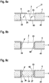
- Fig. 8 a shows the disk set 1 with a first end plate 4 on one side and a second end plate 40 on the other side.
- a first tab 6 is formed, which is arranged above the recess 2.
- a first bending direction 20 indicates that the first tab 6 is bent in the direction of a wall 22.
- a second tab 60 is formed.
- a second bending direction 21 indicates that the second tab 60 is bent in the direction of a wall 23.
- the walls 22, 23 are located in the recess 2 opposite.
- the disk set 1 with the two end disks 4, 40 is in Fig. 8b) wherein a first arcuate tab 6 'of the first end fin 4 is adjacent to the wall 22 and a second arcuate tab 60' of the second end fin 40 is adjacent to the wall 23.
- the Fig. 8c shows the disk pack 1 with a joined magnet 24.
- the magnet 24 can be joined both from the side of the end plate 4 and from the side of the end plate 40.
- the magnet 24 is between the first tab 6 'and the second tab 60' are arranged in the recess 2.
- a first active surface 26 occurs at the clamping forces caused by the spring back of the first tab 6' in the direction of the recess 2 against the magnet 24.
- the clamping forces on the two active surfaces 26, 27 hold the magnet 24 in the recess 2 in position.
- the disk set 1 has, for example, one or two end plates 4, 40, on each of which 2 tabs 6, 6 ', 60, 60' are integrally formed.
- the magnet 24 is arranged between the two tabs 6 ', 60' and the tabs 6 ', 60' are adjacent to the walls 22, 23, respectively.
- Another possible variant of this embodiment is a disk pack 1 with two end disks 4, 40, each with two lugs 6, 6 ', 60, 60'. In this variant lie between the magnet 24 and the walls 22, 23 in each case two tabs 6 ', 60', which generate by the spring back in the direction of the recess 2 clamping forces and hold the magnet in position.
- fixation of the magnets 24 in the recesses 2 by the clamping forces described can be additionally supported by fabric, friction or form-fitting connections such as gluing, Kunststoffh GmbHnken, Kunststoffumspritzen or other mechanical means to withstand the mechanical and thermal stresses occurring during operation.
- the magnets 24 are formed of neodymium magnet and are characterized by a strong adhesive effect.
Landscapes
- Engineering & Computer Science (AREA)
- Power Engineering (AREA)
- Manufacturing & Machinery (AREA)
- Permanent Field Magnets Of Synchronous Machinery (AREA)
- Iron Core Of Rotating Electric Machines (AREA)
Description
- Die Erfindung betrifft ein Lamellenpaket gemäß dem Oberbegriff des Anspruchs 1.
- Lamellenpakete von Rotoren einer elektrischen Maschine bestehen aus Einzelblechen oder Einzellamellen, die zum Beispiel durch Stanzpaketieren oder Schweißen miteinander verbunden sind. Um ein mögliches Aufblättern der Lamellenpakete beim Fügen der Pakete oder während des Betriebes zu verhindern, ist als Stärkung des Lamellenendes in der Offenlegungsschrift
DE 27 27 490 A1 eine Endlamelle beschrieben, die aus mindestens zwei Lamellen besteht, die miteinander verschweißt sind. - In einer Untergruppe von elektrischen Maschinen sind Permanentmagnete in die Lamellenpakete von Rotoren eingesetzt, die, wie zum Beispiel in der Offenlegungsschrift
DE 103 49 442 A1 beschrieben, durch den Einsatz einer Backlackschicht in den Lamellenpaketen befestigt sind. DieDE102007029719 und dieEP1983634 sind weitere Druckschriften die zum Stand der Technik gehören. - Die erfindungsgemäße Vorrichtung sieht vor ein Lamellenpaket eines Rotors einer elektrischen Maschine mit einer Endlamelle so zu gestalten, dass einerseits das Lamellenpaket gegen ein mögliches Auffächern gesichert ist, und andererseits die im Lamellenpaket eingesetzten Permanentmagnete durch die Endlamelle befestigt sind.
- Vorteilhaft gegenüber dem Stand der Technik ist die Ausführung der Endlamelle als ein Bauteil. Durch diese Ausführung kann möglicherweise auf Schweißnähte am äußeren Rand der Endlamelle zum Verbinden der Einzellamellen teilweise oder ganz verzichtet werden, was sich positiv auf die Eigenschaften der elektrischen Maschine auswirkt, da bei innenlaufenden Rotoren die Wirkungsgradverluste verringert werden.
- Ein weiterer Vorteil gegenüber dem Stand der Technik ist die Möglichkeit, die Magnete, durch an die Endlamelle angeformte Laschen, im Lamellenpaket zu fixieren.
- Die erfindungsgemäße Vorrichtung mit den Merkmalen des unabhängigen Anspruchs hat den Vorteil, dass Lamellenpakete aus Einzellamellen im Gegensatz zu Vollmaterial zur Verringerung von Wirbelströmen beitragen. Zudem stabilisiert die Endlamelle das Lamellenpaket mit den in Ausnehmungen eingreifenden Laschen. Die Laschen greifen axial nach innen in die Ausnehmungen ein. Diese axial verstärkte Verbindung sorgt für ein verwindungssteiferes Lamellenpaket und verhindert ein Auffächern einzelner Lamellen. Die durch die Erfindung stabilisierten Lamellenpakete weisen bessere Transport- sowie Betriebseigenschaften auf. Des Weiteren verringern sich durch den stabileren Verbund des Lamellenpakets die Montagekräfte der Lamellenpakete auf den Rotorträger, was zu einer Vereinfachung des Fügeprozesses und damit zu einer kostengünstigeren und prozeßsichereren Montage führt.
- Durch die in den abhängigen Ansprüchen aufgeführten Maßnahmen sind vorteilhafte Weiterbildungen und Verbesserungen der im unabhängigen Anspruch angegebenen Vorrichtung möglich.
- Die erfindungsgemäße Ausführung der Endlamelle bietet den Vorteil, dass die Endlamelle sowohl einseitig als auch beidseitig an das Lamellenpaket gefügt werden kann, wobei die Montagereihenfolge der Lamellenpakete mit den Magneten abhängig von der einseitigen oder zweiseitigen Anbringung von den Endlamellen ist.
- Eine Ausführungsform des Lamellenpakets, bei dem an beiden Seiten jeweils eine Endlamelle vorgesehen ist, sieht vor, dass die in die Ausnehmung eingreifenden Laschen der beiden Endlamellen auf einer Seite der Ausnehmung zwischen dem gefügten Magneten und einer Wand des Lamellenpakets angeordnet sind. Vorteilhaft an dieser Ausführungsform ist, dass sich die zur Innenseite der Ausnehmung befindlichen Lasche beim Fügen des Magneten nicht aufbiegt, wenn der Magnet in Biegerichtung der Lasche eingeschoben wird.
- Eine weitere Ausführungsform des Lamellenpakets, mit an beiden Seiten vorgesehenden Endlamellen, fixiert vorteilhafter Weise den Magneten auf beiden Seiten der Ausnehmung. Dies wird erreicht, indem eine erste Lasche einer ersten Endlamelle derart gebogen ist, dass die ersten Lasche zu einer ersten Wand der Ausnehmung angeordnet ist und eine zweite Lasche einer zweiten Endlamelle derart gebogen ist, dass die zweite Lasche zu einer der ersten Wand gegenüberliegenden Wand angeordnet ist.
- Für eine Vielzahl von Anwendungen kann es vorteilhaft sein, dass die Laschen der Endlamellen, die zwischen zwei Stegen angeordnet sind, nicht nur über ein radial innenliegendes Joch der Endlamelle miteinander verbunden sind, sondern zusätzlich noch über einen radial außenliegenden Träger. Die Gestaltung der Endlamelle mit oder ohne Träger sorgt je nach Einsatz und Ausgestaltung der Endlamelle für Vorteile im Spannungsverlauf innerhalb der Lamelle. Dieses kann sich positiv auf die Fertigungsqualität der Lamellenpakete und auf die elektrischen Eigenschaften der elektrischen Maschine auswirken.
- Besonders günstig ist die gleiche Anzahl der Laschen der Endlamellen mit der Anzahl von Ausnehmungen der Einzellamellen und der in Umfangsrichtung gleichen Verteilung der Laschen und der Ausnehmungen (auch Magnettaschen genannt). Die Positionierung der Laschen an den Ausnehmungen ermöglicht es, dass in jeder Magnettasche ein Magnet abhängig von der Ausführungsform durch eine oder zwei Laschen in Position gehalten werden kann.
- Aus wirtschaftlichen Gründen ist es vorteilhaft die Endlammelle symmetrisch auszubilden. Dies vereinfacht die Fertigung und ermöglicht eine variable Montage der Endlamellen auf die Einzellamellen. Mit symmetrischen Endlamellen besteht zudem die Möglichkeit der beidseitigen Montage an das Lamellenpaket mit der gleichen Bauform. Die ähnlichen Geometrien der Endlamelle und der Einzellamellen sind vorteilhaft für die Fertigung der Bauteile in Bezug auf Wechselteile und Werkzeuge und ermöglichen eine Fertigung auf der gleichen Fertigungslinie. Des Weiteren kann auf Zusatzbauteile verzichtet werden, wenn die Laschen an den Endlammellen einstückig angeformt sind. Die Endlamelle lässt sich zum Beispiel per Stanzverfahren oder Laserschneiden herstellen und besteht vorteilhafter Weise aus dem gleichen Material wie die Einzellamellen des Lamellenpakets. Alternativ können sich je nach Anforderung die Materialien der Endlamelle und Einzellamellen unterscheiden.
- Besonders günstig ist eine elastisch-plastische Verformbarkeit der Laschen der Endlamelle. Nach dem Biegen der Lasche und dem Fügen des Magneten entsteht in der Ausnehmung eine Klemmkraft an der Wirkfläche zwischen der Lasche und dem Magneten, die zu einem festeren Verbund zwischen den beiden Bauteilen führt. Durch die Klemmkraft können je nach Anwendungsfall zusätzliche Fixierungen der Magnete in den Ausnehmungen wegfallen, wodurch die Herstellungskosten verringert werden. Zudem werden die Magnete in den Ausnehmungen durch die Laschen gehalten, weil Fertigungstoleranzen der Magnete und der Ausnehmungen durch ein Zurückfedern der Laschen ausgeglichen werden.
- Von besonderem Vorteil ist eine Ausführungsform der erfindungsgemäßen Vorrichtung, bei der die Laschen der Endlamelle nach dem Fügen der Endlamelle auf das Lamellenpaket (bestehend aus den Einzellamellen) in die Ausnehmungen gebogen sind. Anschließend ist der Magnet in die Ausnehmung zu fügen. Mögliche Beschädigungen der Magnete beim Fügen in die Ausnehmungen sind durch die vorgebogenen Laschen nahezu ausgeschlossen.
- Die vorteilhafte Gestaltung der Erfindung erlaubt es je nach Anforderung und Einsatzgebiet die Montage der Endlamellen mit den Einzellamellen entweder durch Schweißen oder durch Stanzpaketieren umzusetzen.
- Weitere Vorteile und vorteilhafte Ausgestaltungen des Gegenstands der Erfindung sind in der Beschreibung, den Zeichnungen und den Ansprüchen entnehmbar.
- Ausführungsbeispiele der Erfindung sind in den Zeichnungen dargestellt und in der nachfolgenden Beschreibung näher erläutert.
- Es zeigen:
-
Figur 1 : Eine perspektivische Darstellung eines Lamellenpakets; -
Figur 2 : Eine Draufsicht eines Ausschnitts einer Einzellamelle und einer Endlamelle; -
Figur 3 : Eine Draufsicht eines Ausschnitts einer ersten Ausführungsform einer Endlamelle; -
Figur 4 a) : Eine Draufsicht eines Ausschnitts einer zweiten Ausführungsform einer Endlamelle; -
Figur 4 b) : Eine Draufsicht eines Ausschnitts einer dritten Ausführungsform einer Endlamelle; -
Figur 5 a) bis c) : Schematische Darstellungen einer ersten Ausführungsform eines Lamellenpakets mit einseitiger Endlamelle; -
Figur 6 a) bis c) : Seitenansicht der ersten Ausführungsform eines Lamellenpakets mit einseitiger Endlamelle; -
Figur 7 a) bis c) : Schematische Darstellungen einer zweiten Ausführungsform eines Lamellenpakets mit beidseitiger Endlamelle; -
Figur 8 a) bis c) : Schematische Darstellungen einer vierten Ausführungsform eines Lamellenpakets mit beidseitiger Endlamelle. - Die Erfindung ist anhand der beigefügten Zeichnungen dargestellt und wird in der nachfolgenden Beschreibung näher erläutert.
-
Fig. 1 zeigt ein Lamellenpaket 1, wie es bei Rotoren von elektrischen Maschinen, insbesondere von Hybridfahrzeugen, zum Einsatz kommt. Üblicherweise werden ein oder mehrere Lamellenpakete 1 auf einen Rotorträger aufgepresst oder aufgeschrumpft. Alternativ können die Lamellenpakete 1 auch formschlüssig auf den Rotorträger gefügt werden. Das Lamellenpaket 1 weist in Umfangsrichtung verteilt Ausnehmungen 2 auf, die das Lamellenpaket 1 axial zur Rotorachse (nicht dargestellt) durchlaufen. Diese Ausnehmungen 2 werden auch als Magnettaschen bezeichnet und dienen zur Aufnahme von Magneten 24 (Fig. 5 ). In einer bevorzugten Ausführungsform weist das Lamellenpaket 1 vierundzwanzig Ausnehmungen 2 auf, in der die Magnete 24 aufgenommen werden können. Je nach Anwendung und Größe des Rotors kann die Anzahl der Ausnehmungen 2 variieren. Das Lamellenpaket 1 ist in der hier gezeigten Ausführungsform durch Schweißnähte 3 am inneren Durchmesser zusammengehalten. Eine weitere Möglichkeit zur Verbindung des Lamellenpakets 1 bietet das Stanzpaketieren und/oder das Laserschweißen am Innen- und/oder Außendurchmesser. - In
Fig. 2 ist ein Ausschnitt einer ersten Ausführungsform einer Endlamelle 4 und einer Einzellamelle 5 des Lamellenpakets 1 in axialer Draufsicht dargestellt. Die Endlamelle 4 ist vor der Einzellamelle 5 des Lamellenpakets 1 angeordnet und es ist eine Lasche 6 dargestellt, die vor der Ausnehmung 2 des Lamellenpakets 1 angeordnet ist. Die Form der Lasche 6 ist bevorzugt rechteckig und ist an der freiliegenden Seite der Lasche 6 abgerundet. Das Maß der Länge der Lasche 6 entspricht bevorzugt der axialen Tiefe der Ausnehmung 2 des Lamellenpakets 1. Die Form und die Länge können je nach Anwendungsfall variieren. Die Befestigung der Endlamelle 4 am Lamellenpaket 1 kann zum Beispiel wie inFig. 1 gezeigt über eine Schweißnaht 3 am inneren Durchmesser, oder in hier nicht dargestellter Weise, über Stanzpaketieren ausgeführt sein. - Ein Ausschnitt der ersten Ausführungsform der Endlamelle 4 ist in
Fig. 3 dargestellt. Die Lasche 6 der Endlamelle 4 ist einstückig an einem Steg 10 angeformt und ragt in einen Lamellenausschnitt 13 der Endlamelle 4. Der Steg 10 ist über ein radial innenliegendes Joch 12 mit einem weiteren Steg 11 verbunden. - Ein Ausschnitt einer zweiten Ausführungsform der Endlamelle 4 ist in
Fig. 4 a) dargestellt. Der Ausschnitt zeigt die Endlamelle 4 mit der Lasche 6, die einstückig an der Endlamelle 4 angeformt ist. Die Lasche 6 befindet sich in ungebogenem Zustand in einem Lamellenausschnitt 14 der Endlamelle 4. Die Ränder des Lamellenausschnitts 14 sind radial innenliegend von einem Joch 12 und radial außenliegend am Außenumfang 16 von einem Träger 15 gebildet. In Umfangsrichtung sind die Ränder des Lamellenausschnitts 14 durch Stege 10, 11 ausgebildet. An dem Steg 10 ist die Lasche 6 einstückig angeformt. Diese Ausführungsform der Endlamelle 4 mit Träger 15 bietet je nach Anwendungsfall Vorteile im Spannungsverlauf innerhalb der Endlamelle 4 und somit im Lamellenpaket 1. - In einer dritten Ausführungsform der Endlamelle 4, wie in
Fig. 4 b) dargestellt, sind in dem Lamellenausschnitt 14 zwei ungebogene Laschen 6 am Joch 12 der Endlamelle 4 ausgebildet. Beispielsweise kann auch nur eine Lasche 6 am Joch 12 ausgebildet sein oder mehr als zwei Laschen 6. Gegenüber den Laschen 6 ist der Träger 15 der Endlamelle 4 angeordnet. Alternativ können die Laschen 6 auch am Träger 15 ausgebildet sein. - Die drei gezeigten und weiteren Ausführungsformen der Endlamelle 4, sowie die Einzellamellen 5 können beispielsweise durch Stanzverfahren hergestellt sein. Es ist auch möglich die Endlamellen 4 und Einzellamellen 5 durch weitere Herstellungsverfahren, wie zum Beispiel Laserschneiden oder Wasserstrahlschneiden, zu fertigen.
- Die
Figuren 5 a) bis c) und6 a) bis c) zeigen eine erste Ausführungsform und Montageschritte zur Herstellung eines erfindungsgemäßen Lamellenpakets 1 bestehend aus dem Lamellenpaket 1, der Endlamelle 4 und dem Magneten 24. Es zeigen dieFiguren 5 a) bis c) ein Schnittbild des Lamellenpakets 1 in radialer Richtung, bei denen auf die Einzeldarstellung der Einzellamellen 5 verzichtet wird und dieFiguren 6 a) bis c) zeigen eine Draufsicht des Lamellenpakets 1 in axialer Richtung, bei der die Endlamelle 4 und die letzte Einzellamelle 5 dargestellt sind. - Das Lamellenpaket 1 ist, wie in
Fig. 5 a) zu sehen, in einer einseitigen Ausführung 30 mit einer Endlamelle 4 als Abschluss ausgeführt, wobei die Lasche 6 über der Ausnehmung 2 angeordnet ist. Die Ausnehmung 2 weist in Umfangsrichtung Wände 22, 23 auf. Eine Biegerichtung 20 gibt an, dass in dieser ersten Ausführungsform die Lasche 6 in Richtung der Wand 22 gebogen wird. -
Fig. 5 b) zeigt das Lamellenpaket 1 mit der Endlamelle 4 und einer gebogenen Lasche 6', die zur Wand 22 benachbart ist. In der Ausnehmung 2 gegenüber der Wand 22 ist eine Wand 23 angeordnet. Gebogene Laschen 6', 60' (Fig. 5 b) ,Fig. 7 b) ) werden in der Beschreibung durch hochgestellten Häkchen (') an den Bezugszeichen gekennzeichnet. - In
Fig. 5 c) ist das Lamellenpaket 1 mit der Endlamelle 4 und einem gefügten Magneten 24 dargestellt. Der Magnet 24 ist in der Ausnehmung 2 zwischen der gebogenen Lasche 6' und der Wand 23 angeordnet, wobei er vorzugsweise in Fügerichtung 25 in die Ausnehmung (2) geschoben wird. Zwischen der Lasche 6' und dem Magneten 24 befindet sich eine Wirkfläche 26, an der Klemmkräfte auftreten. Die Klemmkräfte entstehen durch das Zurückfedern der Lasche 6' in Richtung der Ausnehmung 2 und drücken den Magneten 24 in der Ausnehmung 2 gegen die Wand 23 des Lamellenpakets 1 und halten ihn in Position. -
Fig. 6 a) zeigt eine Draufsicht auf die Einzellamelle 5 des Lamellenpakets 1 mit der Ausnehmung 2. InFig. 6 b) ist die Endlamelle 4 mit der Lasche 6 dargestellt, die über der Ausnehmung 2 angeordnet ist.Fig. 6 c) zeigt die in die Ausnehmung 2 gebogene Lasche 6' der Endlamelle 4. Die Endlamelle 4 kann in Dicke und/oder Material von den Einzellamellen 5 des Lamellenpakets 1 abweichen, um eine bestmögliche Klemmkraft auf den Magneten 24 zu erzielen. - Alternativ zu der oben beschriebenen Montagereihenfolge ist es auch möglich die Lasche 6, 6' zu biegen, bevor die Endlamelle 4 auf das Lamellenpaket 1 gefügt wird. In einer Ausgestaltungen der ersten Ausführungsform kann die Endlamelle 4 auch so an dem Lamellenpaket 1 angeordnet sein, dass sich die Lasche 6, 6' auf der Seite der Wand 23 des Lamellenpakets 1 befindet. Des Weiteren kann in einer weiteren Ausgestaltung der ersten Ausführungsform die Endlamelle 4 auf der anderen Seite des Lamellenpakets 1 angeordnet sein, wobei sich die Laschen 6, 6'jeweils an den Wänden 22, 23 anordnen lassen.
- Eine zweite Ausführungsform des Lamellenpakets 1, sowie eine mögliche Montagereihenfolge zeigen die Schnittbilder der
Figuren 7 a) bis c) . Das Lamellenpaket 1 ist in einer beidseitigen Ausführung 31 dargestellt, wobei zwei Endlamellen 4, 40 den Abschluss bilden. Die Endlamellen 4, 40 können zum Beispiel per Stanz- oder Schweißverfahren mit dem Lamellenpaket 1 befestigt sein. -
Fig. 7 a) zeigt das Lamellenpaket 1 mit einer ersten Endlamelle 4 auf der einen und einer zweiten Endlamelle 40 auf der anderen Seite. An der ersten Endlamelle 4 ist eine erste Lasche 6 angeformt, die über der Ausnehmung 2 angeordnet ist. An der zweiten Endlamelle 40 ist eine zweite Lasche 60 angeformt, die der ersten Lasche 6 gegenüber angeordnet ist. Zwischen den Laschen 6, 60 befindet sich die Ausnehmung 2. Eine erste Biegerichtung 20 gibt an, in welche Richtung die erste Lasche 6 gebogen wird und eine zweite Biegerichtung 21 gibt an, in welche Richtung die zweite Lasche 60 gebogen wird. In dieser Darstellung geben die Biegerichungen 20, 21 an, dass die Laschen 6, 60 in Richtung einer Wand 22 in der Ausnehmung 2 gebogen werden. Gegenüber der Wand 22 ist eine Wand 23 angeordnet. - Das Lamellenpaket 1 mit den zwei Endlamellen 4, 40 ist in
Fig. 7 b) dargestellt, wobei eine erste gebogene Lasche 6' der ersten Endlamelle 4 zwischen der Wand 22 und einer zweiten gebogenen Lasche 60' der zweiten Endlamelle 40 liegt. Um die Laschen 6', 60' so zu positionieren, wurde zuerst die erste Lasche 6' gebogen und danach die zweite Lasche 60'. - Die
Fig. 7 c) zeigt das Lamellenpaket 1 mit einem gefügten Magneten 24, der in dieser Ausführungsform bevorzugt in einer Fügerichtung 25 in die Ausnehmung 2 geschoben wurde. Der Magnet 24 ist zwischen der Wand 23 und der zweiten Lasche 60' angeordnet. Die Laschen 6', 60' liegen zwischen dem Magneten 24 und der Wand 22, wobei die erste Lasche 6' zur Wand 22 benachbart und die Lasche 60' zum Magneten 24 benachbart ist. Zwischen dem Magneten 24 und der Lasche 60' befindet sich eine Wirkfläche 26, an der Klemmkräfte auftreten. Die Klemmkräfte entstehen durch das Zurückfedern der ersten Lasche 6' gegen die Lasche 60' und das Zurückfedern der zweiten Lasche 60' in Richtung der Ausnehmung 2. Der Magnet 24 wird somit gegen die Wand 23 gedrückt und in der Ausnehmung 2 des Lamellenpakets 1 in Position gehalten. - Eine vierte Ausführungsform des Lamellenpakets 1, sowie eine mögliche Montagereihenfolge, ist in den
Figuren 8 a) bis c) dargestellt. -
Fig. 8 a) zeigt das Lamellenpaket 1 mit einer ersten Endlamelle 4 auf der einen und einer zweiten Endlamelle 40 auf der anderen Seite. An der ersten Endlamelle 4 ist eine erste Lasche 6 angeformt, die über der Ausnehmung 2 angeordnet ist. Eine erste Biegerichtung 20 gibt an, dass die erste Lasche 6 in Richtung einer Wand 22 gebogen wird. An der zweiten Endlamelle 40 ist eine zweite Lasche 60 angeformt. Eine zweite Biegerichtung 21 gibt an, dass die zweite Lasche 60 in Richtung einer Wand 23 gebogen wird. Die Wände 22, 23 liegen sich in der Ausnehmung 2 gegenüber. - Das Lamellenpaket 1 mit den zwei Endlamellen 4, 40 ist in
Fig. 8 b) dargestellt, wobei eine erste gebogene Lasche 6' der ersten Endlamelle 4 zu der Wand 22 benachbart ist und eine zweite gebogene Lasche 60' der zweiten Endlamelle 40 zu der Wand 23 benachbart ist. - Die
Fig. 8 c) zeigt das Lamellenpaket 1 mit einem gefügten Magneten 24. Der Magnet 24 kann sowohl von der Seite der Endlamelle 4 als auch von der Seite der Endlamelle 40 gefügt werden. Der Magnet 24 ist zwischen der ersten Lasche 6' und der zweiten Lasche 60' in der Ausnehmung 2 angeordnet. Zwischen dem Magneten 24 und der Lasche 6' befindet sich eine erste Wirkfläche 26, an der Klemmkräfte auftreten, die durch das Zurückfedern der ersten Lasche 6' in Richtung der Ausnehmung 2 gegen den Magneten 24 entstehen. Auf der anderen Seite des Magneten 24 befindet sich eine zweite Wirkfläche 27, an der ebenso Klemmkräfte auftreten, die durch das Zurückfedern der zweiten Lasche 60' in Richtung der Ausnehmung 2 entstehen. Die Klemmkräfte an den beiden Wirkflächen 26, 27 halten den Magneten 24 in der Ausnehmung 2 in Position. - Eine weitere nicht dargestellte Ausführungsform des Lamellenpakets 1 weist beispielsweise ein oder zwei Endlamellen 4, 40 auf, an denen jeweils 2 Laschen 6, 6', 60, 60' angeformt sind. In einer möglichen Variante dieser Ausführungsform mit nur einer Endlamelle 4, 40 ist der Magnet 24 zwischen den beiden Laschen 6', 60' angeordnet und die Laschen 6', 60' sind jeweils zu den Wänden 22, 23 benachbart. Eine weitere mögliche Variante dieser Ausführungsform ist ein Lamellenpaket 1 mit zwei Endlamellen 4, 40 mit jeweils zwei Laschen 6, 6', 60, 60'. Bei dieser Variante liegen zwischen dem Magneten 24 und den Wänden 22, 23 jeweils zwei Laschen 6', 60', die durch das Zurückfedern in Richtung der Ausnehmung 2 Klemmkräfte erzeugen und den Magneten in Position halten.
- Die Fixierung der Magnete 24 in den Ausnehmungen 2 durch die beschriebenen Klemmkräfte kann zusätzlich durch Stoff-, Reib- oder Formschlussverbindungen wie zum Beispiel Kleben, Kunstharzdurchtränken, Kunststoffumspritzen oder anderen mechanischen Mitteln unterstützt werden, um den im Betrieb auftretenden mechanischen und thermischen Belastungen standzuhalten.
- In einer möglichen Ausführungsform sind die Magnete 24 (auch Permanentmagnete genannt) aus Neodym-Magnet gebildet und zeichnen sich durch eine starke Haftwirkung aus.
Claims (9)
- Lamellenpaket (1) eines Rotors einer elektrischen Maschine, bestehend aus wenigstens zwei Einzellamellen (5) mit über den Umfang verteilten Ausnehmungen (2) zur Aufnahme von Magneten (24), wobei an mindestens einer Seite des Lamellenpakets (1) eine Endlamelle (4, 40) angeordnet ist, die mit wenigstens einer Lasche (6, 6', 60, 60') zum Eingriff in eine der Ausnehmungen (2) versehen ist, dadurch gekennzeichnet, dass die Lasche (6, 6', 60, 60') derart gebogen ist, dass sie axial nach innen in die Ausnehmung (2) eingreift.
- Lamellenpaket (1) nach einem der vorangehenden Ansprüche, dadurch gekennzeichnet, dass an beiden Seiten des Lamellenpakets (1) jeweils eine Endlamelle (4, 40) vorgesehen ist, deren wenigstens eine Lasche (6, 6', 60, 60') derart gebogen ist, dass jeweils nach Fügen des Magneten (24) in die Ausnehmung (2) eine ersten Lasche (6') einer ersten Endlamelle (4) zu einer Wand (22) des Lamellenpakets (1) benachbart ist und eine zweite Lasche (60') einer zweiten Endlamelle (40) zwischen der ersten Lasche (6') und dem Magneten (24) liegt.
- Lamellenpaket (1) nach einem der Ansprüche 1 oder 2, dadurch gekennzeichnet, dass an beiden Seiten des Lamellenpakets (1) jeweils eine Endlamelle (4, 40) vorgesehen ist, deren wenigstens eine Lasche (6, 6', 60, 60') derart gebogen ist, dass jeweils nach Fügen des Magneten (24) in die Ausnehmung (2) eine ersten Lasche (6') einer ersten Endlamelle (4) zu einer Wand (22) des Lamellenpakets (1) benachbart ist und eine zweite Lasche (60') einer zweiten Endlamelle (40) zu einer Wand (23) des Lamellenpakets (1) benachbart ist.
- Lamellenpaket (1) nach einem der vorangehenden Ansprüche, dadurch gekennzeichnet, dass die Laschen (6, 6', 60, 60') der Endlamelle (4, 40) jeweils zwischen zwei Stegen (10, 11) angeordnet sind, wobei die Stege (10, 11) in Umfangsrichtung über ein radial innenliegendes Joch (12) miteinander verbunden sind.
- Lamellenpaket (1) nach Anspruch 4, dadurch gekennzeichnet, dass die zwei Stege (10, 11) zusätzlich über einen radial außenliegenden Träger (15) verbunden sind, so dass die Endlamellen (4, 40) einen geschlossenen Außenumfang (16) haben.
- Lamellenpaket (1) nach einem der vorangehenden Ansprüche, dadurch gekennzeichnet, dass die Anzahl der Laschen (6, 6', 60, 60') der Endlamelle (4, 40) gleich der Anzahl der Ausnehmungen (2) des Lamellenpakets (1) ist.
- Lamellenpaket (1) nach einem der vorangehenden Ansprüche, dadurch gekennzeichnet, dass die Laschen (6, 6', 60, 60') der Endlamelle (4, 40) in Umfangsrichtung die gleiche Verteilung und die gleichen Abstände aufweisen, wie die Ausnehmungen (2) des Lamellenpakets (1).
- Lamellenpaket (1) nach einem der vorangehenden Ansprüche, dadurch gekennzeichnet, dass die Laschen (6, 6', 60, 60') einstückig an der Endlamelle (4, 40) angeformt sind.
- Lamellenpaket (1) nach einem der vorangehenden Ansprüche, dadurch gekennzeichnet, dass die Laschen (6, 6', 60, 60') derart gebogen sind, dass nach dem Fügen der Magnete (24) in die Ausnehmungen (2) an Wirkflächen (14) zwischen den Laschen (6', 60') und den Magneten (24) eine Klemmkraft besteht.
Applications Claiming Priority (2)
| Application Number | Priority Date | Filing Date | Title |
|---|---|---|---|
| DE102008043138A DE102008043138A1 (de) | 2008-10-23 | 2008-10-23 | Lamellenpaket eines Rotors einer elektrischen Maschine |
| PCT/EP2009/061631 WO2010046177A2 (de) | 2008-10-23 | 2009-09-08 | Lamellenpaket eines rotors einer elektrischen maschine |
Publications (2)
| Publication Number | Publication Date |
|---|---|
| EP2338215A2 EP2338215A2 (de) | 2011-06-29 |
| EP2338215B1 true EP2338215B1 (de) | 2017-07-05 |
Family
ID=42054842
Family Applications (1)
| Application Number | Title | Priority Date | Filing Date |
|---|---|---|---|
| EP09782765.3A Not-in-force EP2338215B1 (de) | 2008-10-23 | 2009-09-08 | Lamellenpaket eines rotors einer elektrischen maschine |
Country Status (3)
| Country | Link |
|---|---|
| EP (1) | EP2338215B1 (de) |
| DE (1) | DE102008043138A1 (de) |
| WO (1) | WO2010046177A2 (de) |
Cited By (1)
| Publication number | Priority date | Publication date | Assignee | Title |
|---|---|---|---|---|
| DE102023107336A1 (de) * | 2023-03-23 | 2024-09-26 | Valeo Eautomotive Germany Gmbh | Rotor für eine elektrische Maschine mit einer verbesserten Befestigung von Rotormagneten in dem Rotorblechpaket |
Families Citing this family (8)
| Publication number | Priority date | Publication date | Assignee | Title |
|---|---|---|---|---|
| DE102010029251A1 (de) * | 2010-05-25 | 2011-12-01 | Robert Bosch Gmbh | Komponente für eine elektriche Maschine sowie Verfahren und Blechlamelle zum Aufbau einer solchen Komponente |
| DE102010030326A1 (de) * | 2010-06-22 | 2011-12-22 | Robert Bosch Gmbh | Befestigung von Einzelmagneten eines Maschinenteils einer elektrischen Maschine |
| US8692432B2 (en) | 2010-12-07 | 2014-04-08 | Regal Beloit America, Inc. | Permanent magnet rotors and methods of assembling the same |
| DE102011122023A1 (de) * | 2011-12-23 | 2013-06-27 | Brose Fahrzeugteile GmbH & Co. Kommanditgesellschaft, Würzburg | Roboterblechpaket eines Elektromotors |
| DE102013020662B4 (de) | 2013-12-06 | 2026-01-08 | Feintool International Holding Ag | Verfahren zur Herstellung von Lamellen für ein Lamellenpaket, insbesondere für elektrische Maschinen und Generatoren, Vorrichtung mit wenigstens einer Stanzpresse sowie nach dem Verfahren hergestellte Lamelle und Lamellenpaket |
| GB201403555D0 (en) | 2014-02-28 | 2014-04-16 | Of America Asrepresented By The Sec Dep Of Health And Human | Interior permanent magnet motor and rotor structure therefore |
| FR3055483B1 (fr) * | 2016-08-31 | 2020-01-03 | Valeo Equipements Electriques Moteur | Rotor de machine electrique tournante muni d'au moins une languette deformable pour le remplissage d'une lame d'air parasite |
| EP3907865A1 (de) | 2020-05-08 | 2021-11-10 | Sonplas GmbH | Verfahren und anordnung zum herstellen einer komponente einer elektrischen maschine |
Family Cites Families (6)
| Publication number | Priority date | Publication date | Assignee | Title |
|---|---|---|---|---|
| DE2727490A1 (de) | 1977-06-18 | 1979-01-04 | Bosch Gmbh Robert | Magnetischer kern |
| DE10349442A1 (de) | 2003-10-23 | 2005-05-25 | Robert Bosch Gmbh | Elektrische Maschine mit Permanentmagnetrotor und Verfahren zu dessen Herstellung |
| ITBO20050437A1 (it) * | 2005-06-30 | 2007-01-01 | Spal Automotive Srl | Rotore per macchina elettrica |
| JP2007174822A (ja) * | 2005-12-22 | 2007-07-05 | Fanuc Ltd | 電動機のロータ及びその製造方法 |
| DE102007029719A1 (de) * | 2007-02-01 | 2008-08-07 | Robert Bosch Gmbh | Elektrische Maschine |
| DE102007015249A1 (de) * | 2007-03-27 | 2008-10-02 | Miele & Cie. Kg | Rotor, insbesondere für einen Elektromotor einer Umwälzpumpe |
-
2008
- 2008-10-23 DE DE102008043138A patent/DE102008043138A1/de not_active Withdrawn
-
2009
- 2009-09-08 EP EP09782765.3A patent/EP2338215B1/de not_active Not-in-force
- 2009-09-08 WO PCT/EP2009/061631 patent/WO2010046177A2/de not_active Ceased
Non-Patent Citations (1)
| Title |
|---|
| None * |
Cited By (1)
| Publication number | Priority date | Publication date | Assignee | Title |
|---|---|---|---|---|
| DE102023107336A1 (de) * | 2023-03-23 | 2024-09-26 | Valeo Eautomotive Germany Gmbh | Rotor für eine elektrische Maschine mit einer verbesserten Befestigung von Rotormagneten in dem Rotorblechpaket |
Also Published As
| Publication number | Publication date |
|---|---|
| DE102008043138A1 (de) | 2010-04-29 |
| WO2010046177A3 (de) | 2010-07-15 |
| EP2338215A2 (de) | 2011-06-29 |
| WO2010046177A2 (de) | 2010-04-29 |
Similar Documents
| Publication | Publication Date | Title |
|---|---|---|
| EP2338215A2 (de) | Lamellenpaket eines rotors einer elektrischen maschine | |
| DE102013012605B4 (de) | Rotierende elektrische Maschine und Verfahren zum Herstellen von Magnetpolschuhen | |
| EP3695486B1 (de) | Elektrische maschine mit einem lamellenpaket zur fixierung eines magneten sowie ein lamellenpaket zur verwendung bei einer solchen maschine | |
| EP2229721A1 (de) | Elektrische maschine | |
| DE102011122023A1 (de) | Roboterblechpaket eines Elektromotors | |
| DE102010004887A1 (de) | Spulenkörper zur Montage an einem Magnetkern, Magnetkern für Reluktanzresolver und Verfahren zur Herstellung | |
| DE102009047485A1 (de) | Elektrische Maschine | |
| WO2008092748A1 (de) | Elektrische maschine | |
| DE102009003228B4 (de) | Elektrische Maschine | |
| DE102011078054A1 (de) | Lamellenpaket mit Magnetfixiernasen für einen Rotor oder Stator einer Elektromaschine | |
| EP4143949B1 (de) | Stator einer elektrischen maschine | |
| WO2008065146A1 (de) | Permanentmagnetrotor mit aufbiegungen zum fixieren der permanentmagnete des rotorpaketes | |
| DE102014225260A1 (de) | Kühlungsoptimiertes Blechpaket für einen permanentmagnetischen Rotor einer elektrischen Maschine | |
| DE102012100332A1 (de) | Stator für eine rotierende elektrische Maschine und Verfahren zu seiner Herstellung | |
| DE102014206848A1 (de) | Baueinheit mit einem lamellierten Blechpaket für eine elektrische Maschine, Verfahren zur Herstellung einer solchen Baueinheit und elektrische Maschine | |
| WO2018138187A1 (de) | Blechpaketscheibe mit einer mehrzahl von blechpaketscheibensegmenten sowie rotor | |
| DE102008041555A1 (de) | Rotoreinheit für eine permanenterregte elektrische Maschine und Verfahren zur Montage von Permanentmagneten | |
| DE102020204576A1 (de) | Lamellenpaket für eine elektrische Maschine, sowie eine elektrische Maschine aufweisend ein Lamellenpaket, und Verfahren zum Herstellen eines Statorgrundkörpers | |
| EP2876789B1 (de) | Verfahren zur Herstellung eines Rotors | |
| DE102022203163A1 (de) | Blechpaket für eine E-Maschine | |
| DE102009034238A1 (de) | Statorsegment und Stator eines Hybrid- oder Elektrofahrzeuges | |
| DE102023204131A1 (de) | Rotor einer elektrischen Maschine, sowie elektrische Maschine aufweisend einen solchen Rotor | |
| EP3785350B1 (de) | Rückschlussring und elektrischer aussenläufermotor | |
| DE102021204845A1 (de) | Lamellenpaket für eine elektrische Maschine sowie Verfahren zur Fertigung des Lamellenpakets | |
| DE102016105510A1 (de) | Statorbaugruppe |
Legal Events
| Date | Code | Title | Description |
|---|---|---|---|
| PUAI | Public reference made under article 153(3) epc to a published international application that has entered the european phase |
Free format text: ORIGINAL CODE: 0009012 |
|
| 17P | Request for examination filed |
Effective date: 20110523 |
|
| AK | Designated contracting states |
Kind code of ref document: A2 Designated state(s): AT BE BG CH CY CZ DE DK EE ES FI FR GB GR HR HU IE IS IT LI LT LU LV MC MK MT NL NO PL PT RO SE SI SK SM TR |
|
| AX | Request for extension of the european patent |
Extension state: AL BA RS |
|
| DAX | Request for extension of the european patent (deleted) | ||
| GRAP | Despatch of communication of intention to grant a patent |
Free format text: ORIGINAL CODE: EPIDOSNIGR1 |
|
| INTG | Intention to grant announced |
Effective date: 20170410 |
|
| GRAS | Grant fee paid |
Free format text: ORIGINAL CODE: EPIDOSNIGR3 |
|
| GRAA | (expected) grant |
Free format text: ORIGINAL CODE: 0009210 |
|
| AK | Designated contracting states |
Kind code of ref document: B1 Designated state(s): AT BE BG CH CY CZ DE DK EE ES FI FR GB GR HR HU IE IS IT LI LT LU LV MC MK MT NL NO PL PT RO SE SI SK SM TR |
|
| REG | Reference to a national code |
Ref country code: GB Ref legal event code: FG4D Free format text: NOT ENGLISH |
|
| REG | Reference to a national code |
Ref country code: CH Ref legal event code: EP |
|
| REG | Reference to a national code |
Ref country code: AT Ref legal event code: REF Ref document number: 907221 Country of ref document: AT Kind code of ref document: T Effective date: 20170715 |
|
| REG | Reference to a national code |
Ref country code: IE Ref legal event code: FG4D Free format text: LANGUAGE OF EP DOCUMENT: GERMAN |
|
| REG | Reference to a national code |
Ref country code: DE Ref legal event code: R096 Ref document number: 502009014131 Country of ref document: DE |
|
| REG | Reference to a national code |
Ref country code: FR Ref legal event code: PLFP Year of fee payment: 9 |
|
| REG | Reference to a national code |
Ref country code: NL Ref legal event code: MP Effective date: 20170705 |
|
| REG | Reference to a national code |
Ref country code: LT Ref legal event code: MG4D |
|
| PG25 | Lapsed in a contracting state [announced via postgrant information from national office to epo] |
Ref country code: NL Free format text: LAPSE BECAUSE OF FAILURE TO SUBMIT A TRANSLATION OF THE DESCRIPTION OR TO PAY THE FEE WITHIN THE PRESCRIBED TIME-LIMIT Effective date: 20170705 Ref country code: FI Free format text: LAPSE BECAUSE OF FAILURE TO SUBMIT A TRANSLATION OF THE DESCRIPTION OR TO PAY THE FEE WITHIN THE PRESCRIBED TIME-LIMIT Effective date: 20170705 Ref country code: HR Free format text: LAPSE BECAUSE OF FAILURE TO SUBMIT A TRANSLATION OF THE DESCRIPTION OR TO PAY THE FEE WITHIN THE PRESCRIBED TIME-LIMIT Effective date: 20170705 Ref country code: LT Free format text: LAPSE BECAUSE OF FAILURE TO SUBMIT A TRANSLATION OF THE DESCRIPTION OR TO PAY THE FEE WITHIN THE PRESCRIBED TIME-LIMIT Effective date: 20170705 Ref country code: NO Free format text: LAPSE BECAUSE OF FAILURE TO SUBMIT A TRANSLATION OF THE DESCRIPTION OR TO PAY THE FEE WITHIN THE PRESCRIBED TIME-LIMIT Effective date: 20171005 Ref country code: SE Free format text: LAPSE BECAUSE OF FAILURE TO SUBMIT A TRANSLATION OF THE DESCRIPTION OR TO PAY THE FEE WITHIN THE PRESCRIBED TIME-LIMIT Effective date: 20170705 |
|
| PG25 | Lapsed in a contracting state [announced via postgrant information from national office to epo] |
Ref country code: PL Free format text: LAPSE BECAUSE OF FAILURE TO SUBMIT A TRANSLATION OF THE DESCRIPTION OR TO PAY THE FEE WITHIN THE PRESCRIBED TIME-LIMIT Effective date: 20170705 Ref country code: GR Free format text: LAPSE BECAUSE OF FAILURE TO SUBMIT A TRANSLATION OF THE DESCRIPTION OR TO PAY THE FEE WITHIN THE PRESCRIBED TIME-LIMIT Effective date: 20171006 Ref country code: BG Free format text: LAPSE BECAUSE OF FAILURE TO SUBMIT A TRANSLATION OF THE DESCRIPTION OR TO PAY THE FEE WITHIN THE PRESCRIBED TIME-LIMIT Effective date: 20171005 Ref country code: ES Free format text: LAPSE BECAUSE OF FAILURE TO SUBMIT A TRANSLATION OF THE DESCRIPTION OR TO PAY THE FEE WITHIN THE PRESCRIBED TIME-LIMIT Effective date: 20170705 Ref country code: LV Free format text: LAPSE BECAUSE OF FAILURE TO SUBMIT A TRANSLATION OF THE DESCRIPTION OR TO PAY THE FEE WITHIN THE PRESCRIBED TIME-LIMIT Effective date: 20170705 Ref country code: IS Free format text: LAPSE BECAUSE OF FAILURE TO SUBMIT A TRANSLATION OF THE DESCRIPTION OR TO PAY THE FEE WITHIN THE PRESCRIBED TIME-LIMIT Effective date: 20171105 |
|
| REG | Reference to a national code |
Ref country code: DE Ref legal event code: R097 Ref document number: 502009014131 Country of ref document: DE |
|
| PG25 | Lapsed in a contracting state [announced via postgrant information from national office to epo] |
Ref country code: CZ Free format text: LAPSE BECAUSE OF FAILURE TO SUBMIT A TRANSLATION OF THE DESCRIPTION OR TO PAY THE FEE WITHIN THE PRESCRIBED TIME-LIMIT Effective date: 20170705 Ref country code: DK Free format text: LAPSE BECAUSE OF FAILURE TO SUBMIT A TRANSLATION OF THE DESCRIPTION OR TO PAY THE FEE WITHIN THE PRESCRIBED TIME-LIMIT Effective date: 20170705 Ref country code: RO Free format text: LAPSE BECAUSE OF FAILURE TO SUBMIT A TRANSLATION OF THE DESCRIPTION OR TO PAY THE FEE WITHIN THE PRESCRIBED TIME-LIMIT Effective date: 20170705 |
|
| REG | Reference to a national code |
Ref country code: CH Ref legal event code: PL |
|
| PLBE | No opposition filed within time limit |
Free format text: ORIGINAL CODE: 0009261 |
|
| STAA | Information on the status of an ep patent application or granted ep patent |
Free format text: STATUS: NO OPPOSITION FILED WITHIN TIME LIMIT |
|
| PG25 | Lapsed in a contracting state [announced via postgrant information from national office to epo] |
Ref country code: SK Free format text: LAPSE BECAUSE OF FAILURE TO SUBMIT A TRANSLATION OF THE DESCRIPTION OR TO PAY THE FEE WITHIN THE PRESCRIBED TIME-LIMIT Effective date: 20170705 Ref country code: MC Free format text: LAPSE BECAUSE OF FAILURE TO SUBMIT A TRANSLATION OF THE DESCRIPTION OR TO PAY THE FEE WITHIN THE PRESCRIBED TIME-LIMIT Effective date: 20170705 Ref country code: SM Free format text: LAPSE BECAUSE OF FAILURE TO SUBMIT A TRANSLATION OF THE DESCRIPTION OR TO PAY THE FEE WITHIN THE PRESCRIBED TIME-LIMIT Effective date: 20170705 Ref country code: IT Free format text: LAPSE BECAUSE OF FAILURE TO SUBMIT A TRANSLATION OF THE DESCRIPTION OR TO PAY THE FEE WITHIN THE PRESCRIBED TIME-LIMIT Effective date: 20170705 Ref country code: EE Free format text: LAPSE BECAUSE OF FAILURE TO SUBMIT A TRANSLATION OF THE DESCRIPTION OR TO PAY THE FEE WITHIN THE PRESCRIBED TIME-LIMIT Effective date: 20170705 |
|
| 26N | No opposition filed |
Effective date: 20180406 |
|
| GBPC | Gb: european patent ceased through non-payment of renewal fee |
Effective date: 20171005 |
|
| REG | Reference to a national code |
Ref country code: IE Ref legal event code: MM4A |
|
| REG | Reference to a national code |
Ref country code: BE Ref legal event code: MM Effective date: 20170930 |
|
| PG25 | Lapsed in a contracting state [announced via postgrant information from national office to epo] |
Ref country code: LU Free format text: LAPSE BECAUSE OF NON-PAYMENT OF DUE FEES Effective date: 20170908 |
|
| PG25 | Lapsed in a contracting state [announced via postgrant information from national office to epo] |
Ref country code: CH Free format text: LAPSE BECAUSE OF NON-PAYMENT OF DUE FEES Effective date: 20170930 Ref country code: IE Free format text: LAPSE BECAUSE OF NON-PAYMENT OF DUE FEES Effective date: 20170908 Ref country code: LI Free format text: LAPSE BECAUSE OF NON-PAYMENT OF DUE FEES Effective date: 20170930 Ref country code: GB Free format text: LAPSE BECAUSE OF NON-PAYMENT OF DUE FEES Effective date: 20171005 |
|
| PG25 | Lapsed in a contracting state [announced via postgrant information from national office to epo] |
Ref country code: SI Free format text: LAPSE BECAUSE OF FAILURE TO SUBMIT A TRANSLATION OF THE DESCRIPTION OR TO PAY THE FEE WITHIN THE PRESCRIBED TIME-LIMIT Effective date: 20170705 Ref country code: BE Free format text: LAPSE BECAUSE OF NON-PAYMENT OF DUE FEES Effective date: 20170930 |
|
| REG | Reference to a national code |
Ref country code: FR Ref legal event code: PLFP Year of fee payment: 10 |
|
| PG25 | Lapsed in a contracting state [announced via postgrant information from national office to epo] |
Ref country code: MT Free format text: LAPSE BECAUSE OF FAILURE TO SUBMIT A TRANSLATION OF THE DESCRIPTION OR TO PAY THE FEE WITHIN THE PRESCRIBED TIME-LIMIT Effective date: 20170705 |
|
| REG | Reference to a national code |
Ref country code: AT Ref legal event code: MM01 Ref document number: 907221 Country of ref document: AT Kind code of ref document: T Effective date: 20170908 |
|
| PG25 | Lapsed in a contracting state [announced via postgrant information from national office to epo] |
Ref country code: AT Free format text: LAPSE BECAUSE OF NON-PAYMENT OF DUE FEES Effective date: 20170908 |
|
| PG25 | Lapsed in a contracting state [announced via postgrant information from national office to epo] |
Ref country code: HU Free format text: LAPSE BECAUSE OF FAILURE TO SUBMIT A TRANSLATION OF THE DESCRIPTION OR TO PAY THE FEE WITHIN THE PRESCRIBED TIME-LIMIT; INVALID AB INITIO Effective date: 20090908 |
|
| PG25 | Lapsed in a contracting state [announced via postgrant information from national office to epo] |
Ref country code: CY Free format text: LAPSE BECAUSE OF NON-PAYMENT OF DUE FEES Effective date: 20170705 |
|
| PGFP | Annual fee paid to national office [announced via postgrant information from national office to epo] |
Ref country code: FR Payment date: 20190924 Year of fee payment: 11 |
|
| PG25 | Lapsed in a contracting state [announced via postgrant information from national office to epo] |
Ref country code: MK Free format text: LAPSE BECAUSE OF FAILURE TO SUBMIT A TRANSLATION OF THE DESCRIPTION OR TO PAY THE FEE WITHIN THE PRESCRIBED TIME-LIMIT Effective date: 20170705 |
|
| PGFP | Annual fee paid to national office [announced via postgrant information from national office to epo] |
Ref country code: DE Payment date: 20191125 Year of fee payment: 11 |
|
| PG25 | Lapsed in a contracting state [announced via postgrant information from national office to epo] |
Ref country code: TR Free format text: LAPSE BECAUSE OF FAILURE TO SUBMIT A TRANSLATION OF THE DESCRIPTION OR TO PAY THE FEE WITHIN THE PRESCRIBED TIME-LIMIT Effective date: 20170705 |
|
| PG25 | Lapsed in a contracting state [announced via postgrant information from national office to epo] |
Ref country code: PT Free format text: LAPSE BECAUSE OF FAILURE TO SUBMIT A TRANSLATION OF THE DESCRIPTION OR TO PAY THE FEE WITHIN THE PRESCRIBED TIME-LIMIT Effective date: 20170705 |
|
| REG | Reference to a national code |
Ref country code: DE Ref legal event code: R119 Ref document number: 502009014131 Country of ref document: DE |
|
| PG25 | Lapsed in a contracting state [announced via postgrant information from national office to epo] |
Ref country code: FR Free format text: LAPSE BECAUSE OF NON-PAYMENT OF DUE FEES Effective date: 20200930 Ref country code: DE Free format text: LAPSE BECAUSE OF NON-PAYMENT OF DUE FEES Effective date: 20210401 |