EP2338215B1 - Paquet de tôles d'un rotor d'un moteur électrique - Google Patents
Paquet de tôles d'un rotor d'un moteur électrique Download PDFInfo
- Publication number
- EP2338215B1 EP2338215B1 EP09782765.3A EP09782765A EP2338215B1 EP 2338215 B1 EP2338215 B1 EP 2338215B1 EP 09782765 A EP09782765 A EP 09782765A EP 2338215 B1 EP2338215 B1 EP 2338215B1
- Authority
- EP
- European Patent Office
- Prior art keywords
- laminated core
- tab
- end plate
- magnet
- lug
- Prior art date
- Legal status (The legal status is an assumption and is not a legal conclusion. Google has not performed a legal analysis and makes no representation as to the accuracy of the status listed.)
- Not-in-force
Links
Images


Classifications
-
- H—ELECTRICITY
- H02—GENERATION; CONVERSION OR DISTRIBUTION OF ELECTRIC POWER
- H02K—DYNAMO-ELECTRIC MACHINES
- H02K1/00—Details of the magnetic circuit
- H02K1/06—Details of the magnetic circuit characterised by the shape, form or construction
- H02K1/22—Rotating parts of the magnetic circuit
- H02K1/27—Rotor cores with permanent magnets
- H02K1/2706—Inner rotors
- H02K1/272—Inner rotors the magnetisation axis of the magnets being perpendicular to the rotor axis
- H02K1/274—Inner rotors the magnetisation axis of the magnets being perpendicular to the rotor axis the rotor consisting of two or more circumferentially positioned magnets
- H02K1/2753—Inner rotors the magnetisation axis of the magnets being perpendicular to the rotor axis the rotor consisting of two or more circumferentially positioned magnets the rotor consisting of magnets or groups of magnets arranged with alternating polarity
- H02K1/276—Magnets embedded in the magnetic core, e.g. interior permanent magnets [IPM]
-
- H—ELECTRICITY
- H02—GENERATION; CONVERSION OR DISTRIBUTION OF ELECTRIC POWER
- H02K—DYNAMO-ELECTRIC MACHINES
- H02K15/00—Methods or apparatus specially adapted for manufacturing, assembling, maintaining or repairing of dynamo-electric machines
- H02K15/02—Methods or apparatus specially adapted for manufacturing, assembling, maintaining or repairing of dynamo-electric machines of stator or rotor bodies
- H02K15/03—Methods or apparatus specially adapted for manufacturing, assembling, maintaining or repairing of dynamo-electric machines of stator or rotor bodies having permanent magnets
Definitions
- the invention relates to a disk pack according to the preamble of claim 1.
- Disk packs of rotors of an electric machine consist of individual sheets or individual laminations, which are connected to each other, for example by stamping or welding.
- Disk packs of rotors of an electric machine consist of individual sheets or individual laminations, which are connected to each other, for example by stamping or welding.
- an end plate which consists of at least two fins, which are welded together.
- the device according to the invention provides for a disk set of a rotor of an electric machine to be designed with an end plate so that on the one hand the disk set is secured against possible fanning, and on the other hand the permanent magnets inserted in the disk set are fixed by the end plate.
- Another advantage over the prior art is the ability to fix the magnets, by integrally formed tabs on the end plate, in the disk set.
- the device according to the invention with the features of the independent claim has the advantage that plate packs made of individual lamellae, in contrast to solid material, contribute to the reduction of eddy currents.
- the end disc stabilizes the disc pack with engaging in recesses tabs. The tabs engage axially inwardly into the recesses.
- This axially reinforced connection ensures a torsion-resistant plate pack and prevents fanning of individual plates.
- the disk packs stabilized by the invention have better transport and operating properties. Furthermore, due to the more stable assembly of the disk set, the assembly forces of the disk packs on the rotor carrier are reduced, which leads to a simplification of the joining process and thus to a more cost-effective and more reliable assembly.
- the inventive design of the end plate has the advantage that the end plate can be joined both on one side and on both sides of the plate pack, the assembly order of the plate packets with the magnet is dependent on the one-sided or two-sided attachment of the end plates.
- An embodiment of the disk pack in which an end plate is provided on both sides, provides that the engaging in the recess tabs of the two end plates are arranged on one side of the recess between the joined magnet and a wall of the disk set.
- An advantage of this embodiment is that the flap located to the inside of the recess does not bounce when joining the magnet when the magnet is inserted in the bending direction of the tab.
- a further embodiment of the disk pack, with end disks provided on both sides, advantageously fixes the magnet on both sides of the recess. This is accomplished by bending a first tab of a first end fin such that the first tab is disposed to a first wall of the recess and a second tab of a second end fin is bent such that the second tab is disposed to a wall opposite the first wall is.
- the tabs of the Endlamellen which are arranged between two webs, not only via a radially inner yoke of the Endlamelle are connected to each other, but additionally via a radially outer support.
- the design of the Endlamelle with or without carrier provides depending on the use and design of Endlamelle advantages in the voltage curve within the lamella. This can have a positive effect on the production quality of the disk packs and on the electrical properties of the electrical machine.
- Particularly favorable is the same number of tabs of the end plates with the number of recesses of the individual lamellae and the same distribution in the circumferential direction of the tabs and the recesses (also called magnetic pockets).
- the positioning of the tabs on the recesses allows a magnet to be held in position in each magnet pocket by one or two tabs depending on the embodiment.
- Endlammelle symmetrical. This simplifies the production and enables variable mounting of the end lamellae on the individual louvers. With symmetrical Endlamellen there is also the possibility of two-sided mounting to the disk pack with the same design.
- the similar geometries of the end plate and the individual lamellae are advantageous for the production of the components in terms of parts and tools change and allow production on the same production line. Furthermore, can be dispensed with additional components when the tabs are integrally formed on the Endlammellen.
- the end plate can be produced for example by punching or laser cutting and advantageously consists of the same material as the individual lamellae of the plate pack. Alternatively, depending on the requirement, the materials of the end lamella and individual lamellae may differ.
- the advantageous design of the invention makes it possible, depending on the requirements and application, to implement the assembly of the end lamellae with the individual lamellae either by welding or by stamped packetizing.
- Fig. 1 shows a disk set 1, as it comes in rotors of electric machines, in particular of hybrid vehicles used.
- one or more plate packs 1 are pressed or shrunk onto a rotor carrier.
- the disk packs 1 can also be positively joined to the rotor carrier.
- the disk set 1 has distributed in the circumferential direction recesses 2, which the disk set 1 axially to the rotor axis (not shown). These recesses 2 are also referred to as magnetic pockets and are used to hold magnets 24 (FIG. Fig. 5 ).
- the disk pack 1 twenty-four recesses 2, in which the magnets 24 can be accommodated.
- the number of recesses 2 may vary.
- the disk set 1 is held together in the embodiment shown here by welds 3 on the inner diameter. Another possibility for connecting the disk pack 1 is the stamped packetizing and / or the laser welding on the inner and / or outer diameter.
- Fig. 2 is a section of a first embodiment of an end plate 4 and a single blade 5 of the disk set 1 shown in axial plan view.
- the end plate 4 is arranged in front of the individual lamella 5 of the lamella packet 1 and a tab 6 is shown, which is arranged in front of the recess 2 of the lamella packet 1.
- the shape of the tab 6 is preferably rectangular and is rounded at the exposed side of the tab 6.
- the measure of the length of the tab 6 preferably corresponds to the axial depth of the recess 2 of the disk pack 1. The shape and the length may vary depending on the application.
- the attachment of the end plate 4 on the plate pack 1 can, for example, as in FIG. 1 shown via a weld 3 on the inner diameter, or in a manner not shown here, be carried out over Punching package.
- a section of the first embodiment of the Endlamelle 4 is in Fig. 3 shown.
- the tab 6 of the end plate 4 is integrally formed on a web 10 and protrudes into a lamella cutout 13 of the end plate 4.
- the web 10 is connected via a radially inner yoke 12 with a further web 11.
- a section of a second embodiment of the Endlamelle 4 is in Fig. 4 a) shown.
- the section shows the end plate 4 with the tab 6, which is integrally formed on the end plate 4.
- the flap 6 is in unbent state in a lamellar cutout 14 of the end lamella 4.
- the edges of the lamellar cutout 14 are radially inwardly formed by a yoke 12 and radially outboard on the outer periphery 16 of a carrier 15.
- the edges of the lamella cutout 14 by webs 10, 11 are formed.
- the tab 6 is integrally formed.
- This embodiment of the end plate 4 with carrier 15 offers depending on the application advantages in the voltage curve within the end plate 4 and thus in the disk set. 1
- two unbent tabs 6 are formed on the yoke 12 of the end plate 4 in the lamella cutout 14.
- only one tab 6 may be formed on the yoke 12 or more than two tabs 6.
- the carrier 15 of the end plate 4 is arranged.
- the tabs 6 may also be formed on the carrier 15.
- the three shown and further embodiments of the end plate 4, as well as the individual lamellae 5 can be produced for example by punching. It is also possible to manufacture the end disks 4 and individual disks 5 by further production methods, such as laser cutting or water jet cutting.
- FIGS. 5 a) to c) and 6 a) to c) show a first embodiment and assembly steps for producing a laminated core 1 according to the invention consisting of the disk set 1, the end plate 4 and the magnet 24. It show the FIGS. 5 a) to c) a sectional view of the disk pack 1 in the radial direction, in which the individual representation of the individual slats 5 is omitted and the FIGS. 6 a) to c) show a plan view of the plate pack 1 in the axial direction, in which the end plate 4 and the last single lamella 5 are shown.
- the disk pack 1 is as in Fig. 5 a) to see executed in a one-sided design 30 with an end plate 4 as a conclusion, wherein the tab 6 is disposed above the recess 2.
- the recess 2 has walls 22, 23 in the circumferential direction.
- a bending direction 20 indicates that in this first embodiment, the tab 6 is bent in the direction of the wall 22.
- Fig. 5b shows the disk set 1 with the end plate 4 and a bent tab 6 ', which is adjacent to the wall 22.
- a wall 23 is arranged in the recess 2 opposite the wall 22, a wall 23 is arranged.
- Curved flaps 6 ', 60' are indicated in the description by superscripts (') at the reference numerals.
- the disc pack 1 is shown with the end plate 4 and a joined magnet 24.
- the magnet 24 is arranged in the recess 2 between the bent tab 6 'and the wall 23, wherein it is preferably pushed in the joining direction 25 in the recess (2).
- an active surface 26 Between the tab 6 'and the magnet 24 is an active surface 26, occur at the clamping forces. The clamping forces caused by the spring-back of the tab 6 'in the direction of the recess 2 and press the magnet 24 in the recess 2 against the wall 23 of the disk pack 1 and hold it in position.
- Fig. 6 a shows a plan view of the single lamella 5 of the plate pack 1 with the recess 2.
- the end plate 4 is shown with the tab 6, which is arranged above the recess 2.
- Fig. 6c) shows the bent into the recess 2 tab 6 'of the end plate 4.
- the end plate 4 may be in thickness and / or material deviate from the individual lamellae 5 of the disk pack 1 in order to achieve the best possible clamping force on the magnet 24.
- the end plate 4 may also be arranged on the plate pack 1 such that the flap 6, 6 'is located on the side of the wall 23 of the plate packet 1. Furthermore, in a further embodiment of the first embodiment, the end plate 4 can be arranged on the other side of the plate pack 1, wherein the tabs 6, 6 'can be arranged on the walls 22, 23 in each case.
- a second embodiment of the disk set 1, as well as a possible assembly sequence show the sectional images of FIGS. 7 a) to c) ,
- the disk set 1 is shown in a two-sided embodiment 31, wherein two end plates 4, 40 form the conclusion.
- the end plates 4, 40 can be fastened, for example, by punching or welding method with the disk set 1.
- Fig. 7 a shows the disk set 1 with a first end plate 4 on one side and a second end plate 40 on the other side.
- a first tab 6 is formed, which is arranged above the recess 2.
- a second tab 60 is formed, which is arranged opposite the first tab 6.
- a first bending direction 20 indicates in which direction the first tab 6 is bent and a second bending direction 21 indicates in which direction the second tab 60 is bent.
- the bending directions 20, 21 indicate that the tabs 6, 60 are bent in the direction of a wall 22 in the recess 2.
- a wall 23 is arranged.
- the disk set 1 with the two end disks 4, 40 is in Fig. 7b) illustrated, wherein a first curved tab 6 'of the first end plate 4 between the wall 22 and a second bent tab 60' of the second end plate 40th lies. In order to position the tabs 6 ', 60', first the first tab 6 'was bent and then the second tab 60'.
- the Fig. 7c shows the disk set 1 with a joined magnet 24, which was preferably pushed in this embodiment in a joining direction 25 in the recess 2.
- the magnet 24 is disposed between the wall 23 and the second tab 60 '.
- the tabs 6 ', 60' are located between the magnet 24 and the wall 22, with the first tab 6 'adjacent to the wall 22 and the tab 60' adjacent to the magnet 24.
- Between the magnet 24 and the tab 60 ' is an active surface 26, occur at the clamping forces.
- the magnet 24 is thus pressed against the wall 23 and in the recess 2 of the disk pack 1 in position held.
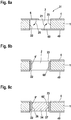
- Fig. 8 a shows the disk set 1 with a first end plate 4 on one side and a second end plate 40 on the other side.
- a first tab 6 is formed, which is arranged above the recess 2.
- a first bending direction 20 indicates that the first tab 6 is bent in the direction of a wall 22.
- a second tab 60 is formed.
- a second bending direction 21 indicates that the second tab 60 is bent in the direction of a wall 23.
- the walls 22, 23 are located in the recess 2 opposite.
- the disk set 1 with the two end disks 4, 40 is in Fig. 8b) wherein a first arcuate tab 6 'of the first end fin 4 is adjacent to the wall 22 and a second arcuate tab 60' of the second end fin 40 is adjacent to the wall 23.
- the Fig. 8c shows the disk pack 1 with a joined magnet 24.
- the magnet 24 can be joined both from the side of the end plate 4 and from the side of the end plate 40.
- the magnet 24 is between the first tab 6 'and the second tab 60' are arranged in the recess 2.
- a first active surface 26 occurs at the clamping forces caused by the spring back of the first tab 6' in the direction of the recess 2 against the magnet 24.
- the clamping forces on the two active surfaces 26, 27 hold the magnet 24 in the recess 2 in position.
- the disk set 1 has, for example, one or two end plates 4, 40, on each of which 2 tabs 6, 6 ', 60, 60' are integrally formed.
- the magnet 24 is arranged between the two tabs 6 ', 60' and the tabs 6 ', 60' are adjacent to the walls 22, 23, respectively.
- Another possible variant of this embodiment is a disk pack 1 with two end disks 4, 40, each with two lugs 6, 6 ', 60, 60'. In this variant lie between the magnet 24 and the walls 22, 23 in each case two tabs 6 ', 60', which generate by the spring back in the direction of the recess 2 clamping forces and hold the magnet in position.
- fixation of the magnets 24 in the recesses 2 by the clamping forces described can be additionally supported by fabric, friction or form-fitting connections such as gluing, Kunststoffh GmbHnken, Kunststoffumspritzen or other mechanical means to withstand the mechanical and thermal stresses occurring during operation.
- the magnets 24 are formed of neodymium magnet and are characterized by a strong adhesive effect.
Claims (9)
- Ensemble de lamelles (1) d'un rotor d'une machine électrique, composé d'au moins deux lamelles individuelles (5) avec des découpes (2) réparties sur la circonférence, destinées à recevoir des aimants (24), dans lequel, sur au moins un côté de l'ensemble de lamelles (1), se trouve une lamelle, d'extrémité (4, 40) qui est dotée d'au moins une patte (6, 6', 60, 60') destinée à s'engager dans l'une des découpes (2), caractérisé en ce que la patte (6, 6', 60, 60') est incurvée de manière à s'engager axialement vers l'intérieur dans la découpe (2).
- Ensemble de lamelles (1) selon l'une quelconque des revendications précédentes, caractérisé en ce que, sur les deux côtés de l'ensemble de lamelles (1), il est respectivement prévu une lamelle d'extrémité (4, 40) dont au moins une patte (6, 6', 60, 60') est incurvée de manière à ce que, après l'assemblage respectif de l'aimant (24) dans la découpe (2), une première patte (6') d'une première lamelle d'extrémité (4) soit adjacente à une paroi (22) de l'ensemble de lamelles (1) et à ce qu'une deuxième patte (60') d'une deuxième lamelle d'extrémité (40) soit située entre la première patte (6') et l'aimant (24).
- Ensemble de lamelles (1) selon l'une quelconque des revendications 1 ou 2, caractérisé en ce que, sur les deux côtés de l'ensemble de lamelles (1), il est respectivement prévu une lamelle d'extrémité (4, 40) dont au moins une patte (6, 6', 60, 60') est incurvée de manière à ce que, après l'assemblage respectif de l'aimant (24) dans la découpe (2), une première patte (6') d'une première lamelle d'extrémité (4) soit adjacente à une paroi (22) de l'ensemble de lamelles (1) et à ce qu'une deuxième patte (60') d'une deuxième lamelle d'extrémité (40) soit adjacente à une paroi (23) de l'ensemble de lamelles (1).
- Ensemble de lamelles (1) selon l'une quelconque des revendications précédentes, caractérisé en ce que les pattes (6, 6', 60, 60') de la lamelle d'extrémité (4, 40) sont respectivement disposées entre deux entretoises (10, 11), dans lequel les entretoises (10, 11) sont reliées l'une à l'autre dans la direction circonférentielle par l'intermédiaire d'un étrier (12) situé radialement vers l'intérieur.
- Ensemble de lamelles (1) selon la revendication 4, caractérisé en ce que les deux entretoises (10, 11) sont en outre reliées par l'intermédiaire d'un support (15) situé radialement vers l'extérieur de manière à ce que les lamelles d'extrémité (4, 40) présentent une périphérie extérieure fermée (16).
- Ensemble de lamelles (1) selon l'une quelconque des revendications précédentes, caractérisé en ce que le nombre des pattes (6, 6', 60, 60') de la lamelle d'extrémité (4, 40) est égal au nombre des découpes (2) des ensembles de lamelles (1).
- Ensemble de lamelles (1) selon l'une quelconque des revendications précédentes, caractérisé en ce que les pattes (6, 6', 60, 60') de la lamelle d'extrémité (4, 40) présentent la même répartition et les mêmes espacements, dans la direction circonférentielle, que les découpes (2) de l'ensemble de lamelles (1).
- Ensemble de lamelles (1) selon l'une quelconque des revendications précédentes, caractérisé en ce que les pattes (6, 6', 60, 60') sont formées d'un seul tenant sur la lamelle d'extrémité (4, 40).
- Ensemble de lamelles (1) selon l'une quelconque des revendications précédentes, caractérisé en ce que les pattes (6, 6', 60, 60') sont incurvées de manière à ce qu'après l'assemblage des aimants (24) dans les découpes (2), une force de serrage s'exerce sur des surfaces actives (14) entre les pattes (6', 60') et les aimants (24).
Applications Claiming Priority (2)
| Application Number | Priority Date | Filing Date | Title |
|---|---|---|---|
| DE102008043138A DE102008043138A1 (de) | 2008-10-23 | 2008-10-23 | Lamellenpaket eines Rotors einer elektrischen Maschine |
| PCT/EP2009/061631 WO2010046177A2 (fr) | 2008-10-23 | 2009-09-08 | Ensemble de lamelles d'un rotor d'une machine électrique |
Publications (2)
| Publication Number | Publication Date |
|---|---|
| EP2338215A2 EP2338215A2 (fr) | 2011-06-29 |
| EP2338215B1 true EP2338215B1 (fr) | 2017-07-05 |
Family
ID=42054842
Family Applications (1)
| Application Number | Title | Priority Date | Filing Date |
|---|---|---|---|
| EP09782765.3A Not-in-force EP2338215B1 (fr) | 2008-10-23 | 2009-09-08 | Paquet de tôles d'un rotor d'un moteur électrique |
Country Status (3)
| Country | Link |
|---|---|
| EP (1) | EP2338215B1 (fr) |
| DE (1) | DE102008043138A1 (fr) |
| WO (1) | WO2010046177A2 (fr) |
Families Citing this family (8)
| Publication number | Priority date | Publication date | Assignee | Title |
|---|---|---|---|---|
| DE102010029251A1 (de) * | 2010-05-25 | 2011-12-01 | Robert Bosch Gmbh | Komponente für eine elektriche Maschine sowie Verfahren und Blechlamelle zum Aufbau einer solchen Komponente |
| DE102010030326A1 (de) * | 2010-06-22 | 2011-12-22 | Robert Bosch Gmbh | Befestigung von Einzelmagneten eines Maschinenteils einer elektrischen Maschine |
| US8692432B2 (en) * | 2010-12-07 | 2014-04-08 | Regal Beloit America, Inc. | Permanent magnet rotors and methods of assembling the same |
| DE102011122023A1 (de) | 2011-12-23 | 2013-06-27 | Brose Fahrzeugteile GmbH & Co. Kommanditgesellschaft, Würzburg | Roboterblechpaket eines Elektromotors |
| DE102013020662A1 (de) | 2013-12-06 | 2015-06-11 | Kienle + Spiess Gmbh | Verfahren zur Herstellung von Lamellen für ein Lamellenpaket, insbesondere für elektrische Maschinen und Generatoren,Vorrichtung mit wenigstens einer Stanzpresse sowie nach dem Verfahren hergestellte Lamelle und Lamellenpaket. |
| GB201403555D0 (en) | 2014-02-28 | 2014-04-16 | Of America Asrepresented By The Sec Dep Of Health And Human | Interior permanent magnet motor and rotor structure therefore |
| FR3055483B1 (fr) * | 2016-08-31 | 2020-01-03 | Valeo Equipements Electriques Moteur | Rotor de machine electrique tournante muni d'au moins une languette deformable pour le remplissage d'une lame d'air parasite |
| EP3907865A1 (fr) | 2020-05-08 | 2021-11-10 | Sonplas GmbH | Procédé et agencement de fabrication d'un composant d'une machine électrique |
Family Cites Families (6)
| Publication number | Priority date | Publication date | Assignee | Title |
|---|---|---|---|---|
| DE2727490A1 (de) | 1977-06-18 | 1979-01-04 | Bosch Gmbh Robert | Magnetischer kern |
| DE10349442A1 (de) | 2003-10-23 | 2005-05-25 | Robert Bosch Gmbh | Elektrische Maschine mit Permanentmagnetrotor und Verfahren zu dessen Herstellung |
| ITBO20050437A1 (it) * | 2005-06-30 | 2007-01-01 | Spal Automotive Srl | Rotore per macchina elettrica |
| JP2007174822A (ja) * | 2005-12-22 | 2007-07-05 | Fanuc Ltd | 電動機のロータ及びその製造方法 |
| DE102007029719A1 (de) * | 2007-02-01 | 2008-08-07 | Robert Bosch Gmbh | Elektrische Maschine |
| DE102007015249A1 (de) * | 2007-03-27 | 2008-10-02 | Miele & Cie. Kg | Rotor, insbesondere für einen Elektromotor einer Umwälzpumpe |
-
2008
- 2008-10-23 DE DE102008043138A patent/DE102008043138A1/de not_active Withdrawn
-
2009
- 2009-09-08 EP EP09782765.3A patent/EP2338215B1/fr not_active Not-in-force
- 2009-09-08 WO PCT/EP2009/061631 patent/WO2010046177A2/fr active Application Filing
Non-Patent Citations (1)
| Title |
|---|
| None * |
Also Published As
| Publication number | Publication date |
|---|---|
| EP2338215A2 (fr) | 2011-06-29 |
| WO2010046177A3 (fr) | 2010-07-15 |
| WO2010046177A2 (fr) | 2010-04-29 |
| DE102008043138A1 (de) | 2010-04-29 |
Similar Documents
| Publication | Publication Date | Title |
|---|---|---|
| EP2338215B1 (fr) | Paquet de tôles d'un rotor d'un moteur électrique | |
| DE19507233C2 (de) | Transversalflußmaschine mit Permanenterregung und mehrsträngiger Ankerwicklung | |
| EP2229721A1 (fr) | Machine électrique | |
| DE102011122023A1 (de) | Roboterblechpaket eines Elektromotors | |
| WO2008092748A1 (fr) | Machine électrique | |
| WO2008034864A1 (fr) | stator à refroidissement par liquide pour machine électrique | |
| DE102010004887A1 (de) | Spulenkörper zur Montage an einem Magnetkern, Magnetkern für Reluktanzresolver und Verfahren zur Herstellung | |
| DE102009047485A1 (de) | Elektrische Maschine | |
| DE102006056873A1 (de) | Permanentmagnetrotor mit Aufbiegungen zum Fixieren der Permanentmagnete des Rotorpaketes | |
| WO2019072538A1 (fr) | Machine électrique comprenant un paquet de lamelles pour fixer un aimant et paquet de lamelles destiné à être utilisé avec une telle machine | |
| DE102012100332A1 (de) | Stator für eine rotierende elektrische Maschine und Verfahren zu seiner Herstellung | |
| DE102011078054A1 (de) | Lamellenpaket mit Magnetfixiernasen für einen Rotor oder Stator einer Elektromaschine | |
| DE102013215812A1 (de) | Elektrische Maschine | |
| WO2011026795A1 (fr) | Stator ayant des têtes de dents fabriquées de façon séparée | |
| DE102009003228A1 (de) | Elektrische Maschine | |
| DE102014206848A1 (de) | Baueinheit mit einem lamellierten Blechpaket für eine elektrische Maschine, Verfahren zur Herstellung einer solchen Baueinheit und elektrische Maschine | |
| DE102008041555A1 (de) | Rotoreinheit für eine permanenterregte elektrische Maschine und Verfahren zur Montage von Permanentmagneten | |
| WO2018138187A1 (fr) | Anneau de noyau feuilleté comprenant une pluralité de segments d'anneau de noyau feuilleté, et rotor | |
| EP2876789B1 (fr) | Procédé de fabrication d'un rotor | |
| DE102009001035A1 (de) | Rotoranordnung für einen Elektromotor | |
| WO2021204830A1 (fr) | Noyau feuilleté pour une machine électrique, machine électrique à noyau feuilleté et procédé de fabrication d'une partie principale de stator | |
| DE102006044965A1 (de) | Gehäuselose elektrische Maschine mit Flüssigkeitskühlung | |
| DE102016105510A1 (de) | Statorbaugruppe | |
| DE102016218822A1 (de) | Stator für eine elektrische Maschine, elektrische Maschine für ein Kraftfahrzeug und Kraftfahrzeug | |
| DE102009034238A1 (de) | Statorsegment und Stator eines Hybrid- oder Elektrofahrzeuges |
Legal Events
| Date | Code | Title | Description |
|---|---|---|---|
| PUAI | Public reference made under article 153(3) epc to a published international application that has entered the european phase |
Free format text: ORIGINAL CODE: 0009012 |
|
| 17P | Request for examination filed |
Effective date: 20110523 |
|
| AK | Designated contracting states |
Kind code of ref document: A2 Designated state(s): AT BE BG CH CY CZ DE DK EE ES FI FR GB GR HR HU IE IS IT LI LT LU LV MC MK MT NL NO PL PT RO SE SI SK SM TR |
|
| AX | Request for extension of the european patent |
Extension state: AL BA RS |
|
| DAX | Request for extension of the european patent (deleted) | ||
| GRAP | Despatch of communication of intention to grant a patent |
Free format text: ORIGINAL CODE: EPIDOSNIGR1 |
|
| INTG | Intention to grant announced |
Effective date: 20170410 |
|
| GRAS | Grant fee paid |
Free format text: ORIGINAL CODE: EPIDOSNIGR3 |
|
| GRAA | (expected) grant |
Free format text: ORIGINAL CODE: 0009210 |
|
| AK | Designated contracting states |
Kind code of ref document: B1 Designated state(s): AT BE BG CH CY CZ DE DK EE ES FI FR GB GR HR HU IE IS IT LI LT LU LV MC MK MT NL NO PL PT RO SE SI SK SM TR |
|
| REG | Reference to a national code |
Ref country code: GB Ref legal event code: FG4D Free format text: NOT ENGLISH |
|
| REG | Reference to a national code |
Ref country code: CH Ref legal event code: EP |
|
| REG | Reference to a national code |
Ref country code: AT Ref legal event code: REF Ref document number: 907221 Country of ref document: AT Kind code of ref document: T Effective date: 20170715 |
|
| REG | Reference to a national code |
Ref country code: IE Ref legal event code: FG4D Free format text: LANGUAGE OF EP DOCUMENT: GERMAN |
|
| REG | Reference to a national code |
Ref country code: DE Ref legal event code: R096 Ref document number: 502009014131 Country of ref document: DE |
|
| REG | Reference to a national code |
Ref country code: FR Ref legal event code: PLFP Year of fee payment: 9 |
|
| REG | Reference to a national code |
Ref country code: NL Ref legal event code: MP Effective date: 20170705 |
|
| REG | Reference to a national code |
Ref country code: LT Ref legal event code: MG4D |
|
| PG25 | Lapsed in a contracting state [announced via postgrant information from national office to epo] |
Ref country code: NL Free format text: LAPSE BECAUSE OF FAILURE TO SUBMIT A TRANSLATION OF THE DESCRIPTION OR TO PAY THE FEE WITHIN THE PRESCRIBED TIME-LIMIT Effective date: 20170705 Ref country code: FI Free format text: LAPSE BECAUSE OF FAILURE TO SUBMIT A TRANSLATION OF THE DESCRIPTION OR TO PAY THE FEE WITHIN THE PRESCRIBED TIME-LIMIT Effective date: 20170705 Ref country code: HR Free format text: LAPSE BECAUSE OF FAILURE TO SUBMIT A TRANSLATION OF THE DESCRIPTION OR TO PAY THE FEE WITHIN THE PRESCRIBED TIME-LIMIT Effective date: 20170705 Ref country code: LT Free format text: LAPSE BECAUSE OF FAILURE TO SUBMIT A TRANSLATION OF THE DESCRIPTION OR TO PAY THE FEE WITHIN THE PRESCRIBED TIME-LIMIT Effective date: 20170705 Ref country code: NO Free format text: LAPSE BECAUSE OF FAILURE TO SUBMIT A TRANSLATION OF THE DESCRIPTION OR TO PAY THE FEE WITHIN THE PRESCRIBED TIME-LIMIT Effective date: 20171005 Ref country code: SE Free format text: LAPSE BECAUSE OF FAILURE TO SUBMIT A TRANSLATION OF THE DESCRIPTION OR TO PAY THE FEE WITHIN THE PRESCRIBED TIME-LIMIT Effective date: 20170705 |
|
| PG25 | Lapsed in a contracting state [announced via postgrant information from national office to epo] |
Ref country code: PL Free format text: LAPSE BECAUSE OF FAILURE TO SUBMIT A TRANSLATION OF THE DESCRIPTION OR TO PAY THE FEE WITHIN THE PRESCRIBED TIME-LIMIT Effective date: 20170705 Ref country code: GR Free format text: LAPSE BECAUSE OF FAILURE TO SUBMIT A TRANSLATION OF THE DESCRIPTION OR TO PAY THE FEE WITHIN THE PRESCRIBED TIME-LIMIT Effective date: 20171006 Ref country code: BG Free format text: LAPSE BECAUSE OF FAILURE TO SUBMIT A TRANSLATION OF THE DESCRIPTION OR TO PAY THE FEE WITHIN THE PRESCRIBED TIME-LIMIT Effective date: 20171005 Ref country code: ES Free format text: LAPSE BECAUSE OF FAILURE TO SUBMIT A TRANSLATION OF THE DESCRIPTION OR TO PAY THE FEE WITHIN THE PRESCRIBED TIME-LIMIT Effective date: 20170705 Ref country code: LV Free format text: LAPSE BECAUSE OF FAILURE TO SUBMIT A TRANSLATION OF THE DESCRIPTION OR TO PAY THE FEE WITHIN THE PRESCRIBED TIME-LIMIT Effective date: 20170705 Ref country code: IS Free format text: LAPSE BECAUSE OF FAILURE TO SUBMIT A TRANSLATION OF THE DESCRIPTION OR TO PAY THE FEE WITHIN THE PRESCRIBED TIME-LIMIT Effective date: 20171105 |
|
| REG | Reference to a national code |
Ref country code: DE Ref legal event code: R097 Ref document number: 502009014131 Country of ref document: DE |
|
| PG25 | Lapsed in a contracting state [announced via postgrant information from national office to epo] |
Ref country code: CZ Free format text: LAPSE BECAUSE OF FAILURE TO SUBMIT A TRANSLATION OF THE DESCRIPTION OR TO PAY THE FEE WITHIN THE PRESCRIBED TIME-LIMIT Effective date: 20170705 Ref country code: DK Free format text: LAPSE BECAUSE OF FAILURE TO SUBMIT A TRANSLATION OF THE DESCRIPTION OR TO PAY THE FEE WITHIN THE PRESCRIBED TIME-LIMIT Effective date: 20170705 Ref country code: RO Free format text: LAPSE BECAUSE OF FAILURE TO SUBMIT A TRANSLATION OF THE DESCRIPTION OR TO PAY THE FEE WITHIN THE PRESCRIBED TIME-LIMIT Effective date: 20170705 |
|
| REG | Reference to a national code |
Ref country code: CH Ref legal event code: PL |
|
| PLBE | No opposition filed within time limit |
Free format text: ORIGINAL CODE: 0009261 |
|
| STAA | Information on the status of an ep patent application or granted ep patent |
Free format text: STATUS: NO OPPOSITION FILED WITHIN TIME LIMIT |
|
| PG25 | Lapsed in a contracting state [announced via postgrant information from national office to epo] |
Ref country code: SK Free format text: LAPSE BECAUSE OF FAILURE TO SUBMIT A TRANSLATION OF THE DESCRIPTION OR TO PAY THE FEE WITHIN THE PRESCRIBED TIME-LIMIT Effective date: 20170705 Ref country code: MC Free format text: LAPSE BECAUSE OF FAILURE TO SUBMIT A TRANSLATION OF THE DESCRIPTION OR TO PAY THE FEE WITHIN THE PRESCRIBED TIME-LIMIT Effective date: 20170705 Ref country code: SM Free format text: LAPSE BECAUSE OF FAILURE TO SUBMIT A TRANSLATION OF THE DESCRIPTION OR TO PAY THE FEE WITHIN THE PRESCRIBED TIME-LIMIT Effective date: 20170705 Ref country code: IT Free format text: LAPSE BECAUSE OF FAILURE TO SUBMIT A TRANSLATION OF THE DESCRIPTION OR TO PAY THE FEE WITHIN THE PRESCRIBED TIME-LIMIT Effective date: 20170705 Ref country code: EE Free format text: LAPSE BECAUSE OF FAILURE TO SUBMIT A TRANSLATION OF THE DESCRIPTION OR TO PAY THE FEE WITHIN THE PRESCRIBED TIME-LIMIT Effective date: 20170705 |
|
| 26N | No opposition filed |
Effective date: 20180406 |
|
| GBPC | Gb: european patent ceased through non-payment of renewal fee |
Effective date: 20171005 |
|
| REG | Reference to a national code |
Ref country code: IE Ref legal event code: MM4A |
|
| REG | Reference to a national code |
Ref country code: BE Ref legal event code: MM Effective date: 20170930 |
|
| PG25 | Lapsed in a contracting state [announced via postgrant information from national office to epo] |
Ref country code: LU Free format text: LAPSE BECAUSE OF NON-PAYMENT OF DUE FEES Effective date: 20170908 |
|
| PG25 | Lapsed in a contracting state [announced via postgrant information from national office to epo] |
Ref country code: CH Free format text: LAPSE BECAUSE OF NON-PAYMENT OF DUE FEES Effective date: 20170930 Ref country code: IE Free format text: LAPSE BECAUSE OF NON-PAYMENT OF DUE FEES Effective date: 20170908 Ref country code: LI Free format text: LAPSE BECAUSE OF NON-PAYMENT OF DUE FEES Effective date: 20170930 Ref country code: GB Free format text: LAPSE BECAUSE OF NON-PAYMENT OF DUE FEES Effective date: 20171005 |
|
| PG25 | Lapsed in a contracting state [announced via postgrant information from national office to epo] |
Ref country code: SI Free format text: LAPSE BECAUSE OF FAILURE TO SUBMIT A TRANSLATION OF THE DESCRIPTION OR TO PAY THE FEE WITHIN THE PRESCRIBED TIME-LIMIT Effective date: 20170705 Ref country code: BE Free format text: LAPSE BECAUSE OF NON-PAYMENT OF DUE FEES Effective date: 20170930 |
|
| REG | Reference to a national code |
Ref country code: FR Ref legal event code: PLFP Year of fee payment: 10 |
|
| PG25 | Lapsed in a contracting state [announced via postgrant information from national office to epo] |
Ref country code: MT Free format text: LAPSE BECAUSE OF FAILURE TO SUBMIT A TRANSLATION OF THE DESCRIPTION OR TO PAY THE FEE WITHIN THE PRESCRIBED TIME-LIMIT Effective date: 20170705 |
|
| REG | Reference to a national code |
Ref country code: AT Ref legal event code: MM01 Ref document number: 907221 Country of ref document: AT Kind code of ref document: T Effective date: 20170908 |
|
| PG25 | Lapsed in a contracting state [announced via postgrant information from national office to epo] |
Ref country code: AT Free format text: LAPSE BECAUSE OF NON-PAYMENT OF DUE FEES Effective date: 20170908 |
|
| PG25 | Lapsed in a contracting state [announced via postgrant information from national office to epo] |
Ref country code: HU Free format text: LAPSE BECAUSE OF FAILURE TO SUBMIT A TRANSLATION OF THE DESCRIPTION OR TO PAY THE FEE WITHIN THE PRESCRIBED TIME-LIMIT; INVALID AB INITIO Effective date: 20090908 |
|
| PG25 | Lapsed in a contracting state [announced via postgrant information from national office to epo] |
Ref country code: CY Free format text: LAPSE BECAUSE OF NON-PAYMENT OF DUE FEES Effective date: 20170705 |
|
| PGFP | Annual fee paid to national office [announced via postgrant information from national office to epo] |
Ref country code: FR Payment date: 20190924 Year of fee payment: 11 |
|
| PG25 | Lapsed in a contracting state [announced via postgrant information from national office to epo] |
Ref country code: MK Free format text: LAPSE BECAUSE OF FAILURE TO SUBMIT A TRANSLATION OF THE DESCRIPTION OR TO PAY THE FEE WITHIN THE PRESCRIBED TIME-LIMIT Effective date: 20170705 |
|
| PGFP | Annual fee paid to national office [announced via postgrant information from national office to epo] |
Ref country code: DE Payment date: 20191125 Year of fee payment: 11 |
|
| PG25 | Lapsed in a contracting state [announced via postgrant information from national office to epo] |
Ref country code: TR Free format text: LAPSE BECAUSE OF FAILURE TO SUBMIT A TRANSLATION OF THE DESCRIPTION OR TO PAY THE FEE WITHIN THE PRESCRIBED TIME-LIMIT Effective date: 20170705 |
|
| PG25 | Lapsed in a contracting state [announced via postgrant information from national office to epo] |
Ref country code: PT Free format text: LAPSE BECAUSE OF FAILURE TO SUBMIT A TRANSLATION OF THE DESCRIPTION OR TO PAY THE FEE WITHIN THE PRESCRIBED TIME-LIMIT Effective date: 20170705 |
|
| REG | Reference to a national code |
Ref country code: DE Ref legal event code: R119 Ref document number: 502009014131 Country of ref document: DE |
|
| PG25 | Lapsed in a contracting state [announced via postgrant information from national office to epo] |
Ref country code: FR Free format text: LAPSE BECAUSE OF NON-PAYMENT OF DUE FEES Effective date: 20200930 Ref country code: DE Free format text: LAPSE BECAUSE OF NON-PAYMENT OF DUE FEES Effective date: 20210401 |