EP2337715B1 - Verfahren zum betrieb eines bremssystems in einem fahrzeug - Google Patents
Verfahren zum betrieb eines bremssystems in einem fahrzeug Download PDFInfo
- Publication number
- EP2337715B1 EP2337715B1 EP09782171.4A EP09782171A EP2337715B1 EP 2337715 B1 EP2337715 B1 EP 2337715B1 EP 09782171 A EP09782171 A EP 09782171A EP 2337715 B1 EP2337715 B1 EP 2337715B1
- Authority
- EP
- European Patent Office
- Prior art keywords
- vehicle
- brake device
- brake
- vehicle according
- braking
- Prior art date
- Legal status (The legal status is an assumption and is not a legal conclusion. Google has not performed a legal analysis and makes no representation as to the accuracy of the status listed.)
- Active
Links
Images
Classifications
-
- B—PERFORMING OPERATIONS; TRANSPORTING
- B60—VEHICLES IN GENERAL
- B60T—VEHICLE BRAKE CONTROL SYSTEMS OR PARTS THEREOF; BRAKE CONTROL SYSTEMS OR PARTS THEREOF, IN GENERAL; ARRANGEMENT OF BRAKING ELEMENTS ON VEHICLES IN GENERAL; PORTABLE DEVICES FOR PREVENTING UNWANTED MOVEMENT OF VEHICLES; VEHICLE MODIFICATIONS TO FACILITATE COOLING OF BRAKES
- B60T1/00—Arrangements of braking elements, i.e. of those parts where braking effect occurs specially for vehicles
- B60T1/02—Arrangements of braking elements, i.e. of those parts where braking effect occurs specially for vehicles acting by retarding wheels
- B60T1/10—Arrangements of braking elements, i.e. of those parts where braking effect occurs specially for vehicles acting by retarding wheels by utilising wheel movement for accumulating energy, e.g. driving air compressors
-
- B—PERFORMING OPERATIONS; TRANSPORTING
- B60—VEHICLES IN GENERAL
- B60K—ARRANGEMENT OR MOUNTING OF PROPULSION UNITS OR OF TRANSMISSIONS IN VEHICLES; ARRANGEMENT OR MOUNTING OF PLURAL DIVERSE PRIME-MOVERS IN VEHICLES; AUXILIARY DRIVES FOR VEHICLES; INSTRUMENTATION OR DASHBOARDS FOR VEHICLES; ARRANGEMENTS IN CONNECTION WITH COOLING, AIR INTAKE, GAS EXHAUST OR FUEL SUPPLY OF PROPULSION UNITS IN VEHICLES
- B60K6/00—Arrangement or mounting of plural diverse prime-movers for mutual or common propulsion, e.g. hybrid propulsion systems comprising electric motors and internal combustion engines
- B60K6/20—Arrangement or mounting of plural diverse prime-movers for mutual or common propulsion, e.g. hybrid propulsion systems comprising electric motors and internal combustion engines the prime-movers consisting of electric motors and internal combustion engines, e.g. HEVs
- B60K6/42—Arrangement or mounting of plural diverse prime-movers for mutual or common propulsion, e.g. hybrid propulsion systems comprising electric motors and internal combustion engines the prime-movers consisting of electric motors and internal combustion engines, e.g. HEVs characterised by the architecture of the hybrid electric vehicle
- B60K6/48—Parallel type
-
- B—PERFORMING OPERATIONS; TRANSPORTING
- B60—VEHICLES IN GENERAL
- B60K—ARRANGEMENT OR MOUNTING OF PROPULSION UNITS OR OF TRANSMISSIONS IN VEHICLES; ARRANGEMENT OR MOUNTING OF PLURAL DIVERSE PRIME-MOVERS IN VEHICLES; AUXILIARY DRIVES FOR VEHICLES; INSTRUMENTATION OR DASHBOARDS FOR VEHICLES; ARRANGEMENTS IN CONNECTION WITH COOLING, AIR INTAKE, GAS EXHAUST OR FUEL SUPPLY OF PROPULSION UNITS IN VEHICLES
- B60K6/00—Arrangement or mounting of plural diverse prime-movers for mutual or common propulsion, e.g. hybrid propulsion systems comprising electric motors and internal combustion engines
- B60K6/20—Arrangement or mounting of plural diverse prime-movers for mutual or common propulsion, e.g. hybrid propulsion systems comprising electric motors and internal combustion engines the prime-movers consisting of electric motors and internal combustion engines, e.g. HEVs
- B60K6/50—Architecture of the driveline characterised by arrangement or kind of transmission units
- B60K6/52—Driving a plurality of drive axles, e.g. four-wheel drive
-
- B—PERFORMING OPERATIONS; TRANSPORTING
- B60—VEHICLES IN GENERAL
- B60L—PROPULSION OF ELECTRICALLY-PROPELLED VEHICLES; SUPPLYING ELECTRIC POWER FOR AUXILIARY EQUIPMENT OF ELECTRICALLY-PROPELLED VEHICLES; ELECTRODYNAMIC BRAKE SYSTEMS FOR VEHICLES IN GENERAL; MAGNETIC SUSPENSION OR LEVITATION FOR VEHICLES; MONITORING OPERATING VARIABLES OF ELECTRICALLY-PROPELLED VEHICLES; ELECTRIC SAFETY DEVICES FOR ELECTRICALLY-PROPELLED VEHICLES
- B60L7/00—Electrodynamic brake systems for vehicles in general
- B60L7/10—Dynamic electric regenerative braking
- B60L7/18—Controlling the braking effect
-
- B—PERFORMING OPERATIONS; TRANSPORTING
- B60—VEHICLES IN GENERAL
- B60L—PROPULSION OF ELECTRICALLY-PROPELLED VEHICLES; SUPPLYING ELECTRIC POWER FOR AUXILIARY EQUIPMENT OF ELECTRICALLY-PROPELLED VEHICLES; ELECTRODYNAMIC BRAKE SYSTEMS FOR VEHICLES IN GENERAL; MAGNETIC SUSPENSION OR LEVITATION FOR VEHICLES; MONITORING OPERATING VARIABLES OF ELECTRICALLY-PROPELLED VEHICLES; ELECTRIC SAFETY DEVICES FOR ELECTRICALLY-PROPELLED VEHICLES
- B60L7/00—Electrodynamic brake systems for vehicles in general
- B60L7/24—Electrodynamic brake systems for vehicles in general with additional mechanical or electromagnetic braking
- B60L7/26—Controlling the braking effect
-
- B—PERFORMING OPERATIONS; TRANSPORTING
- B60—VEHICLES IN GENERAL
- B60T—VEHICLE BRAKE CONTROL SYSTEMS OR PARTS THEREOF; BRAKE CONTROL SYSTEMS OR PARTS THEREOF, IN GENERAL; ARRANGEMENT OF BRAKING ELEMENTS ON VEHICLES IN GENERAL; PORTABLE DEVICES FOR PREVENTING UNWANTED MOVEMENT OF VEHICLES; VEHICLE MODIFICATIONS TO FACILITATE COOLING OF BRAKES
- B60T7/00—Brake-action initiating means
- B60T7/12—Brake-action initiating means for automatic initiation; for initiation not subject to will of driver or passenger
-
- B—PERFORMING OPERATIONS; TRANSPORTING
- B60—VEHICLES IN GENERAL
- B60W—CONJOINT CONTROL OF VEHICLE SUB-UNITS OF DIFFERENT TYPE OR DIFFERENT FUNCTION; CONTROL SYSTEMS SPECIALLY ADAPTED FOR HYBRID VEHICLES; ROAD VEHICLE DRIVE CONTROL SYSTEMS FOR PURPOSES NOT RELATED TO THE CONTROL OF A PARTICULAR SUB-UNIT
- B60W10/00—Conjoint control of vehicle sub-units of different type or different function
- B60W10/04—Conjoint control of vehicle sub-units of different type or different function including control of propulsion units
- B60W10/08—Conjoint control of vehicle sub-units of different type or different function including control of propulsion units including control of electric propulsion units, e.g. motors or generators
-
- B—PERFORMING OPERATIONS; TRANSPORTING
- B60—VEHICLES IN GENERAL
- B60W—CONJOINT CONTROL OF VEHICLE SUB-UNITS OF DIFFERENT TYPE OR DIFFERENT FUNCTION; CONTROL SYSTEMS SPECIALLY ADAPTED FOR HYBRID VEHICLES; ROAD VEHICLE DRIVE CONTROL SYSTEMS FOR PURPOSES NOT RELATED TO THE CONTROL OF A PARTICULAR SUB-UNIT
- B60W10/00—Conjoint control of vehicle sub-units of different type or different function
- B60W10/18—Conjoint control of vehicle sub-units of different type or different function including control of braking systems
- B60W10/184—Conjoint control of vehicle sub-units of different type or different function including control of braking systems with wheel brakes
-
- B—PERFORMING OPERATIONS; TRANSPORTING
- B60—VEHICLES IN GENERAL
- B60W—CONJOINT CONTROL OF VEHICLE SUB-UNITS OF DIFFERENT TYPE OR DIFFERENT FUNCTION; CONTROL SYSTEMS SPECIALLY ADAPTED FOR HYBRID VEHICLES; ROAD VEHICLE DRIVE CONTROL SYSTEMS FOR PURPOSES NOT RELATED TO THE CONTROL OF A PARTICULAR SUB-UNIT
- B60W30/00—Purposes of road vehicle drive control systems not related to the control of a particular sub-unit, e.g. of systems using conjoint control of vehicle sub-units
- B60W30/18—Propelling the vehicle
- B60W30/18009—Propelling the vehicle related to particular drive situations
- B60W30/18109—Braking
- B60W30/18127—Regenerative braking
-
- B—PERFORMING OPERATIONS; TRANSPORTING
- B60—VEHICLES IN GENERAL
- B60T—VEHICLE BRAKE CONTROL SYSTEMS OR PARTS THEREOF; BRAKE CONTROL SYSTEMS OR PARTS THEREOF, IN GENERAL; ARRANGEMENT OF BRAKING ELEMENTS ON VEHICLES IN GENERAL; PORTABLE DEVICES FOR PREVENTING UNWANTED MOVEMENT OF VEHICLES; VEHICLE MODIFICATIONS TO FACILITATE COOLING OF BRAKES
- B60T2270/00—Further aspects of brake control systems not otherwise provided for
- B60T2270/60—Regenerative braking
- B60T2270/602—ABS features related thereto
-
- B—PERFORMING OPERATIONS; TRANSPORTING
- B60—VEHICLES IN GENERAL
- B60T—VEHICLE BRAKE CONTROL SYSTEMS OR PARTS THEREOF; BRAKE CONTROL SYSTEMS OR PARTS THEREOF, IN GENERAL; ARRANGEMENT OF BRAKING ELEMENTS ON VEHICLES IN GENERAL; PORTABLE DEVICES FOR PREVENTING UNWANTED MOVEMENT OF VEHICLES; VEHICLE MODIFICATIONS TO FACILITATE COOLING OF BRAKES
- B60T2270/00—Further aspects of brake control systems not otherwise provided for
- B60T2270/60—Regenerative braking
- B60T2270/608—Electronic brake distribution (EBV/EBD) features related thereto
-
- B—PERFORMING OPERATIONS; TRANSPORTING
- B60—VEHICLES IN GENERAL
- B60T—VEHICLE BRAKE CONTROL SYSTEMS OR PARTS THEREOF; BRAKE CONTROL SYSTEMS OR PARTS THEREOF, IN GENERAL; ARRANGEMENT OF BRAKING ELEMENTS ON VEHICLES IN GENERAL; PORTABLE DEVICES FOR PREVENTING UNWANTED MOVEMENT OF VEHICLES; VEHICLE MODIFICATIONS TO FACILITATE COOLING OF BRAKES
- B60T2270/00—Further aspects of brake control systems not otherwise provided for
- B60T2270/60—Regenerative braking
- B60T2270/613—ESP features related thereto
-
- B—PERFORMING OPERATIONS; TRANSPORTING
- B60—VEHICLES IN GENERAL
- B60W—CONJOINT CONTROL OF VEHICLE SUB-UNITS OF DIFFERENT TYPE OR DIFFERENT FUNCTION; CONTROL SYSTEMS SPECIALLY ADAPTED FOR HYBRID VEHICLES; ROAD VEHICLE DRIVE CONTROL SYSTEMS FOR PURPOSES NOT RELATED TO THE CONTROL OF A PARTICULAR SUB-UNIT
- B60W2520/00—Input parameters relating to overall vehicle dynamics
- B60W2520/10—Longitudinal speed
-
- B—PERFORMING OPERATIONS; TRANSPORTING
- B60—VEHICLES IN GENERAL
- B60W—CONJOINT CONTROL OF VEHICLE SUB-UNITS OF DIFFERENT TYPE OR DIFFERENT FUNCTION; CONTROL SYSTEMS SPECIALLY ADAPTED FOR HYBRID VEHICLES; ROAD VEHICLE DRIVE CONTROL SYSTEMS FOR PURPOSES NOT RELATED TO THE CONTROL OF A PARTICULAR SUB-UNIT
- B60W2520/00—Input parameters relating to overall vehicle dynamics
- B60W2520/26—Wheel slip
-
- B—PERFORMING OPERATIONS; TRANSPORTING
- B60—VEHICLES IN GENERAL
- B60W—CONJOINT CONTROL OF VEHICLE SUB-UNITS OF DIFFERENT TYPE OR DIFFERENT FUNCTION; CONTROL SYSTEMS SPECIALLY ADAPTED FOR HYBRID VEHICLES; ROAD VEHICLE DRIVE CONTROL SYSTEMS FOR PURPOSES NOT RELATED TO THE CONTROL OF A PARTICULAR SUB-UNIT
- B60W2530/00—Input parameters relating to vehicle conditions or values, not covered by groups B60W2510/00 or B60W2520/00
- B60W2530/10—Weight
-
- Y—GENERAL TAGGING OF NEW TECHNOLOGICAL DEVELOPMENTS; GENERAL TAGGING OF CROSS-SECTIONAL TECHNOLOGIES SPANNING OVER SEVERAL SECTIONS OF THE IPC; TECHNICAL SUBJECTS COVERED BY FORMER USPC CROSS-REFERENCE ART COLLECTIONS [XRACs] AND DIGESTS
- Y02—TECHNOLOGIES OR APPLICATIONS FOR MITIGATION OR ADAPTATION AGAINST CLIMATE CHANGE
- Y02T—CLIMATE CHANGE MITIGATION TECHNOLOGIES RELATED TO TRANSPORTATION
- Y02T10/00—Road transport of goods or passengers
- Y02T10/60—Other road transportation technologies with climate change mitigation effect
- Y02T10/62—Hybrid vehicles
Definitions
- the invention relates to a vehicle with a brake system according to the preamble of claim 1.
- Braking systems in vehicles that are provided with a hybrid drive consisting of an internal combustion engine and an electric motor, usually have a braking device on a vehicle axle with a mechanical access of the brake pedal to the braking unit, whereas an electronically controllable, so-called by-wire braking device on the other vehicle axle is arranged, which is set solely via control signals of a regulating or control device.
- the electric drive motor which is part of the hybrid drive, also acts on the axis with the electronically controllable braking device. If the vehicle is braked, the electric motor is switched to generator operation for braking energy recuperation, in which the current generated by the electric motor is used to charge the battery assigned to the electric motor.
- the resulting additional braking torque must be taken into account when generating a target braking torque that is specified by the driver.
- the superimposition or blending of the braking torque resulting from generator operation with the braking torque on the vehicle axle on which the electric motor is active requires activation with appropriate pressure provision on the electronically controllable braking device, what with a corresponding component load on this brake goes hand in hand.
- the EP 1 792 797 A1 discloses a braking system in a vehicle with a first braking device on a first vehicle axle and a second braking device on a second vehicle axle. After the motor vehicle has come to a standstill, the entire braking torque is applied via the driven axle. This is to avoid tensioning the body via opposing drive and braking torques. If the braking force on the braked axle is not sufficient to keep the vehicle at a standstill, the braking device on the second axle is also actuated.
- the EP 0 361 708 A2 shows a vehicle with an electric motor drive and a hydraulic brake system, which is equipped with a regeneration unit.
- the regeneration unit comprises an accumulator, which serves for the temporary storage of hydraulic fluid of the brake system.
- the invention has for its object to improve the service life or stability of a vehicle brake system, which comprises a first braking device with mechanical engagement of the brake pedal and also a second braking device, wherein the second braking device can be designed as a by-wire braking device.
- the vehicle according to the invention has a braking system, the braking system having at least a first braking device and a second, completely or partially independent braking device, and the first braking device having a direct mechanical engagement of the brake pedal on the braking unit of the first braking device in the sense of a conventional, mechanical-hydraulic Has actuation, whereas the second brake device is preferably electronically controllable, that is, designed as a by-wire brake.
- the braking unit of the electronically controllable braking device is set via control signals, which are generated in a regulating or control device as a function of current requirements by the driver or a vehicle control system as well as the current vehicle condition and the ambient conditions.
- the first braking device with a mechanical grip on the brake pedal is not subject to any restriction with regard to the number of brake operations, so that the shifting of the brake actuation from the second braking device to the first braking device with a mechanical grip has no negative effects overall.
- the control strategy of only actuating one braking device and leaving the second, preferably electronically controllable braking device unactuated, is only possible in cases in which a vehicle system size does not exceed an assigned limit value.
- the vehicle system size is, in particular, a vehicle condition size, preferably the vehicle speed, which for safety reasons is below a low limit value of, for example, 5 km / h or 10 km / h, in particular when the vehicle is at a standstill, so that the controllable braking device also during a braking operation remains unactuated and only the first brake device is actuated with a mechanical grip on the brake pedal. Due to the relatively low kinetic energy of the vehicle at low speeds, the braking process can be carried out without impairing driving safety by omitting the actuation of the second, preferably electronically controllable braking device.
- further conditions can be formulated, which must be available alternatively and in particular also cumulatively, so that the braking process is carried out with activation of only the first braking device.
- the wheel slip on at least one wheel can be considered, with activation of the strategy according to the invention only being considered comes when the wheel slip does not exceed an assigned limit.
- vehicle parameters such as certain vehicle parameters can also be taken into account, for example the load state of the vehicle, the braking strategy according to the invention being carried out only if the load state is in particular on gradients below a limit value.
- the activation state of one or more vehicle control systems can also be taken into account. If, for example, an electronic stability program (ESP), an anti-lock braking system (ABS) or a traction control (TCS) is active, the braking process is usually initiated on all wheels of the vehicle for safety reasons, i.e. also with activation of the second, preferably electronically controllable braking device. Conversely, the braking strategy according to the invention is expediently only considered when the vehicle control systems are not in operation.
- ESP electronic stability program
- ABS anti-lock braking system
- TCS traction control
- the braking strategy according to the invention is expediently only considered when the vehicle control systems are not in operation.
- the braking strategy can be activated both in the case of a manual brake intervention by the driver and in the case of an automatically generated brake intervention by a vehicle control system, provided that all conditions for the activation of the brake strategy according to the invention are met.
- the braking strategy according to the invention can be terminated if one of the activation conditions is no longer met. For example, in the course of a braking process with activation of only the first braking device, it may happen that the vehicle speed exceeds the limit speed or that an impermissibly high wheel slip occurs on one or more wheels or that a vehicle control system becomes active. In these cases, the braking strategy according to the invention is terminated and it becomes returned to a regular braking process in which both braking devices are active and generate a braking torque.
- the vehicle according to the invention is equipped with a hybrid drive which comprises an internal combustion engine and an electric drive motor, the electric motor being effective on the same vehicle axis as the second braking device.
- the electric motor drive acts, for example, on the rear axle of the vehicle, on which the preferably electronically controllable braking device is also arranged, whereas on the wheels of the front axle, the braking device with mechanical engagement of the brake pedal is effective.
- the electric drive motor for braking energy recuperation can be switched to generator operation, in which a current that feeds the battery of the electric motor is generated.
- the electric motor generates an additional braking torque which is superimposed on the braking torque which is generated by the braking system of the vehicle.
- the total braking torque is composed of the braking torque of the electric motor and the braking torque of the braking system in the motor vehicle.
- the braking device effective, preferably electronically controllable, on the rear axle remains unactuated; rather, only the braking torque of the electric motor acts on this axle.
- the first braking device is active on the front axle and generates a braking torque.
- Electrohydraulic brakes or brakes that can be actuated by an electric motor, for example, can be used as the electronically controllable braking device.
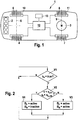
- the illustrated motor vehicle 1 is equipped with a hybrid drive, consisting of a reciprocating piston internal combustion engine 2 and an electric motor 3.
- the internal combustion engine 2 either drives the front wheels 4, 5 on the front axle 6 or the rear wheels 7, 8 on the rear axle 9 or all wheels of the vehicle on.
- the electric motor 3 as part of the hybrid drive sits on the rear axle and drives the rear axle wheels 7 and 8.
- the motor vehicle 1 is equipped with two braking devices 10 and 11 on the front axle 6 and on the rear axle 9 which are separate with regard to their action or the control, the front, first braking device 10 being designed in such a way that the driver The brake pedal to be actuated has a direct mechanical grip on the brake unit of the front brake device, whereas the rear second brake device 11 is designed as an electronically controllable by-wire brake.
- the front brake device 10 is, for example, a hydraulically actuable brake
- the rear brake device 11 is an electrohydraulic brake or an electromotive brake.
- the energy supply to the rear brake device 11 can optionally be independent of the energy supply to the front brake device 10.
- All units of the internal combustion engine that is to say both the motor drives and the braking devices and possibly further devices in the motor vehicle, are set via control signals from a regulating or control device 12.
- sensor signals from an on-board sensor system 13 are also processed.
- Fig. 2 is a flow diagram for the implementation of a component-friendly braking process is shown, in which in certain driving situations only the in Fig. 1 shown front brake device 10, but not the rear brake device 11 is actuated.
- a query is first made as to whether the vehicle is in a braking state, both driving situations in which the driver initiates a braking request by actuating the brake pedal and driving situations in which signals from a vehicle control system, such as an electronic system, are detected Stability Program (ESP) an automatic or automatic brake application is carried out.
- ESP Stability Program
- the brake actuation is queried symbolically using a logical variable b s , which represents the current actuation state of the brake system.
- the variable b s is set to the value "true” if the brake system in the motor vehicle is actuated; otherwise the value of the logical variable b s is set to "false".
- the logical variable b s is set to "true” and the query in method step V1 is fulfilled. In this case, the yes branch ("Y") is continued to the next method step V2. Otherwise there is no request to actuate the vehicle brake and, following the No branch ("N"), the process returns to the beginning of the first method step V1, whereupon a query is carried out again at cyclical intervals.
- step V2 at least one, preferably several, different conditions can be queried, which preferably have to be met cumulatively in order for a braking operation that is gentle on the components to be carried out according to the invention becomes.
- These conditions include, on the one hand, a query regarding the vehicle speed v and, on the other hand, a query about the wheel slip s l . Only in the event that the vehicle speed v falls below a vehicle limit speed v Lim and, furthermore, the wheel slip s l also falls below an assigned limit value s l, Lim , the yes branching continues to the next method step V4, according to which the braking process according to the invention which is gentle on the components is initiated or is carried out.
- step V3 a conventional braking process with actuation of both the front braking device - referred to as B F in method step V3 - and the rear braking device - as B R designated - is carried out.
- this is identified by the term "active".
- method step V4 If, on the other hand, the conditions formulated in method step V2 are met cumulatively, the yes branch can be followed to method step V4, which is carried out as an alternative to method step V3.
- the vehicle is in a stable state in which the vehicle speed is lower than the limit speed s 1, Lim, for example at 5 km / h or 10 km / h, and in which there is little or no wheel slip.
- a further condition can be formulated in method step V2 that no vehicle control system may actively intervene in the driving situation.
- the front braking device B F is activated under the conditions mentioned, whereas the rear braking device B R is deactivated or is not put into operation at all.
- the braking process thus takes place solely by actuating the front brake and, if appropriate, via the braking torque which, in the case of hybrid drives, is generated by the electric drive motor running in generator operation becomes.
- the rear brake on the other hand, is not active, so that no brake pressure has to be maintained at this brake.
- the entire scheme is run through again and again checked whether, on the one hand, the braking process is maintained (process step V1) and, on the other hand, whether the conditions for the existence of the asymmetrical brake actuation with exclusive brake application of the front brake B F (process step 2 ) still or available again.
Landscapes
- Engineering & Computer Science (AREA)
- Transportation (AREA)
- Mechanical Engineering (AREA)
- Chemical & Material Sciences (AREA)
- Combustion & Propulsion (AREA)
- Power Engineering (AREA)
- Physics & Mathematics (AREA)
- Electromagnetism (AREA)
- Automation & Control Theory (AREA)
- Regulating Braking Force (AREA)
- Hybrid Electric Vehicles (AREA)
Description
- Die Erfindung bezieht sich auf ein Fahrzeug mit einem Bremssystem nach dem Oberbegriff des Anspruches 1.
- Bremssysteme in Fahrzeugen, die mit einem Hybridantrieb versehen sind, bestehend aus einem Verbrennungsmotor und einem Elektromotor, weisen üblicherweise an einer Fahrzeugachse eine Bremseinrichtung mit mechanischem Durchgriff des Bremspedals zur Bremseinheit auf, wohingegen an der anderen Fahrzeugachse eine elektronisch ansteuerbare, sogenannte by-wire-Bremseinrichtung angeordnet ist, die allein über Stellsignale eines Regel- bzw. Steuergerätes eingestellt wird. An der Achse mit der elektronisch ansteuerbaren Bremseinrichtung wirkt in der Regel auch der elektrische Antriebsmotor, welcher Teil des Hybridantriebs ist. Wird das Fahrzeug abgebremst, so wird der Elektromotor zur Bremsenergie-Rekuperation in den Generatorbetrieb geschaltet, in welchem der erzeugte Strom des Elektromotors zum Laden der dem Elektromotor zugeordneten Batterie verwendet wird. Das hierbei entstehende zusätzliche Bremsmoment muss bei der Erzeugung eines Sollbremsmoments berücksichtigt werden, das vom Fahrers vorgegeben wird. Die Überlagerung bzw. Verblendung des aus dem Generatorbetrieb entstehenden Bremsmomentes mit dem Bremsmoment an der Fahrzeugachse, an der der Elektromotor wirksam ist, setzt eine Aktivierung mit entsprechender Druckbereitstellung an der elektronisch ansteuerbaren Bremseinrichtung voraus, was mit einer entsprechenden Bauteilbelastung an dieser Bremse einhergeht.
- Die
EP 1 792 797 A1 offenbart ein Bremssystem in einem Fahrzeug mit einer ersten Bremseinrichtung an einer ersten Fahrzeugachse und einer zweiten Bremseinrichtung an einer zweiten Fahrzeugachse. Nach einem Stillstand des Kraftfahrzeugs wird das gesamte Bremsmoment über die angetriebene Achse aufgebracht. Hierdurch soll ein Verspannen der Karosserie über gegenläufige Antriebs- und Bremsmomente vermieden werden. Falls die Bremskraft an der gebremsten Achse nicht ausreicht, um das Fahrzeug im Stillstand zu halten, wird zusätzlich auch die Bremseinrichtung an der zweiten Achse betätigt. - Die
EP 0 361 708 A2 zeigt ein Fahrzeug mit elektromotorischem Antrieb und einem hydraulischen Bremssystem, das mit einer Regenerationseinheit ausgestattet ist. Die Regenerationseinheit umfasst einen Akkumulator, der zum Zwischenspeichern von Hydraulikfluid des Bremssystems dient. - Ergänzend wird zum Stand der Technik auf die
US 2008/0234909 A1 undGB 1 074 051 - Der Erfindung liegt die Aufgabe zugrunde, die Betriebsdauer bzw. Standfestigkeit eines Fahrzeug-Bremssystems zu verbessern, das eine erste Bremseinrichtung mit mechanischem Durchgriff des Bremspedals und darüber hinaus eine zweite Bremseinrichtung umfasst, wobei die zweite Bremseinrichtung als by-wire-Bremseinrichtung ausgebildet sein kann.
- Diese Aufgabe wird erfindungsgemäß bei einem Fahrzeug mit den Merkmalen des Anspruches 1 gelöst. Die Unteransprüche geben zweckmäßige Weiterbildungen an.
- Das erfindungsgemäße Fahrzeug weist ein Bremssystem auf, wobei das Bremssystem mindestens eine erste Bremseinrichtung und eine zweite, ganz oder teilweise unabhängige Bremseinrichtung aufweist und die erste Bremseinrichtung einen unmittelbaren, mechanischen Durchgriff des Bremspedals auf die Bremseinheit der ersten Bremseinrichtung im Sinne einer herkömmlichen, mechanisch-hydraulischen Betätigung aufweist, wohingegen die zweite Bremseinrichtung vorzugsweise elektronisch ansteuerbar ist, also als by-wire-Bremse ausgeführt ist. Die Bremseinheit der elektronisch ansteuerbaren Bremseinrichtung wird über Stellsignale eingestellt, welche in einem Regel- bzw. Steuergerät als Funktion aktueller Anforderungen vom Fahrer oder eines Fahrzeugregelsystems sowie des momentanen Fahrzeugzustandes und der Umgebungsbedingungen erzeugt werden. Da die Auslegung derartiger Bremseinrichtungen hinsichtlich der Anzahl der Bremsbetätigungen bei Kosten und Gewicht hohen Einfluss hat, wird bei einem Betrieb nach dem erfindungsgemäßen Verfahren in definierten Betriebszuständen bei einer Bremsmomentanforderung an das Bremssystem des Fahrzeuges lediglich die erste, unmittelbare über das Bremspedal betätigbare Bremseinrichtung beaufschlagt, wohingehend die vorzugsweise elektronisch ansteuerbare, zweite Bremseinrichtung unbetätigt bleibt. Auf diese Weise wird die Anzahl von Bremsbetätigungen an der zweiten Bremseinrichtung reduziert und damit die Lebensdauer erhöht bzw. es kann hinsichtlich der Kosten und des Gewichts (geringere Baugröße) eine bessere Lösung erzielt werden. Die erste Bremseinrichtung mit mechanischem Durchgriff des Bremspedals unterliegt dagegen keiner Beschränkung hinsichtlich der Anzahl an Bremsbetätigungen, so dass die Verlagerung von Bremsbetätigung von der zweiten Bremseinrichtung auf die erste Bremseinrichtung mit mechanischem Durchgriff insgesamt keine negativen Auswirkungen zur Folge hat.
- Die Ansteuerstrategie, lediglich eine Bremseinrichtung zu betätigen und die zweite, bevorzugt elektronisch ansteuerbare Bremseinrichtung unbetätigt zu lassen, kommt nur in Fällen in Frage, in denen eine Fahrzeug-Systemgröße einen zugeordneten Grenzwert nicht überschreitet. Bei der Fahrzeug-Systemgröße handelt es sich insbesondere um eine Fahrzeugzustandsgröße, vorzugsweise um die Fahrzeuggeschwindigkeit, die aus Sicherheitsgründen unterhalb eines niedrigen Grenzwertes von beispielsweise 5 km/h oder 10 km/h liegt, insbesondere im Stillstand, damit die ansteuerbare Bremseinrichtung auch bei einem Bremsvorgang unbetätigt bleibt und lediglich die erste Bremseinrichtung mit mechanischem Durchgriff des Bremspedals betätigt wird. Aufgrund der verhältnismäßig geringen kinetischen Energie des Fahrzeuges bei niedrigen Geschwindigkeiten kann der Bremsvorgang ohne Beeinträchtigung der Fahrsicherheit unter Weglassen der Betätigung der zweiten, bevorzugt elektronisch ansteuerbaren Bremseinrichtung durchgeführt werden.
- Darüber hinaus können weitere Bedingungen formuliert werden, die alternativ und insbesondere auch kumulativ vorliegen müssen, damit der Bremsvorgang mit Aktivierung lediglich der ersten Bremseinrichtung durchgeführt wird. Hierbei kann insbesondere der Radschlupf an mindestens einem Rad betrachtet werden, wobei eine Aktivierung der erfindungsgemäßen Strategie nur in Betracht kommt, wenn der Radschlupf einen zugeordneten Grenzwert nicht überschreitet. Des Weiteren können auch Fahrzeugkenngrößen wie bestimmte Fahrzeugparameter Berücksichtigung finden, beispielsweise der Beladungszustand des Fahrzeugs, wobei die erfindungsgemäße Bremsstrategie nur durchgeführt wird, wenn der Beladungszustand insbesondere an Steigungen unterhalb eines Grenzwertes liegt.
- Außerdem kommt die Berücksichtigung des Aktivierungszustandes von einem oder von mehreren Fahrzeugregelsystemen in Betracht. Ist beispielsweise ein elektronisches Stabilitätsprogramm (ESP), ein Antiblockiersystem (ABS) oder eine Traktionskontrolle (TCS) aktiv, so wird üblicherweise aus Sicherheitsgründen der Bremsvorgang auf sämtliche Räder des Fahrzeuges eingeleitet, also auch mit Aktivierung der zweiten, bevorzugt elektronisch ansteuerbaren Bremseinrichtung. Umgekehrt kommt die erfindungsgemäße Bremsstrategie zweckmäßigerweise nur in Betracht, wenn die Fahrzeugregelsysteme sich nicht in Funktion befinden.
- Die Aktivierung der Bremsstrategie kann sowohl bei einem manuellen Bremseingriff durch den Fahrer als auch bei einem automatisch generierten Bremseingriff durch ein Fahrzeugregelsystem durchgeführt werden, sofern sämtliche Bedingungen für die Aktivierung der erfindungsgemäßen Bremsstrategie erfüllt sind.
- Eine Beendigung der erfindungsgemäßen Bremsstrategie kommt in Betracht, wenn eine der Aktivierungsbedingungen nicht länger erfüllt ist. So kann es beispielsweise im Laufe eines Bremsvorganges mit Aktivierung nur der ersten Bremseinrichtung vorkommen, dass die Fahrzeuggeschwindigkeit die Grenzgeschwindigkeit überschreitet oder dass an einem oder an mehreren Rädern ein unzulässig hoher Radschlupf auftritt oder dass ein Fahrzeugregelsystem aktiv wird. In diesen Fällen wird die erfindungsgemäße Bremsstrategie abgebrochen und es wird zu einem regulären Bremsvorgang zurückgekehrt, bei dem beide Bremseinrichtungen aktiv sind und ein Bremsmoment erzeugen.
- Das erfindungsgemäße Fahrzeug ist mit einem Hybridantrieb ausgestattet, der eine Brennkraftmaschine sowie einen elektrischen Antriebsmotor umfasst, wobei der Elektromotor an der gleichen Fahrzeugachse wie die zweite Bremseinrichtung wirksam ist. Der elektromotorische Antrieb wirkt beispielsweise auf die Hinterachse des Fahrzeuges, an der auch die bevorzugt elektronisch ansteuerbare Bremseinrichtung angeordnet ist, wohingegen an den Rädern der Vorderachse die Bremseinrichtung mit mechanischem Durchgriff des Bremspedals wirksam ist. Im Bremsbetrieb kann der elektrische Antriebsmotor zur Bremsenergie-Rekuperation in den Generatorbetrieb geschaltet werden, in welchem ein die Batterie des Elektromotors speisender Strom erzeugt wird. Hierbei generiert der Elektromotor ein zusätzliches Bremsmoment, welches dem Bremsmoment überlagert wird, das von dem Bremssystem des Fahrzeuges erzeugt wird. Das Gesamt-Bremsmoment setzt sich aus dem Bremsmoment des Elektromotors sowie dem Bremsmoment des Bremssystems im Kraftfahrzeug zusammen. Bei der erfindungsgemäßen Bremsstrategie bleibt die an der Hinterachse wirksame, vorzugsweise elektronisch ansteuerbare Bremseinrichtung unbetätigt, an dieser Achse wirkt vielmehr nur das Bremsmoment des Elektromotors. An der Vorderachse ist die erste Bremseinrichtung aktiv und erzeugt ein Bremsmoment.
- Als elektronisch ansteuerbare Bremseinrichtung können beispielsweise elektrohydraulische Bremsen oder elektromotorisch betätigbare Bremsen eingesetzt werden.
- Weitere Vorteile und zweckmäßige Ausführungen sind den weiteren Ansprüchen, der Figurenbeschreibung und den Zeichnungen zu entnehmen. Es zeigen:
- Fig. 1
- in schematischer Darstellung ein Kraftfahrzeug mit Hybridantrieb, bestehend aus einem Verbrennungsmotor und einem Elektromotor, mit einer ersten Bremseinrichtung an der Vorderachse und einer zweiten, elektronisch ansteuerbaren Bremseinrichtung an der Hinterachse,
- Fig. 2
- ein Ablaufschema zur Durchführung des Verfahrens zum Betrieb des Bremssystems.
- Das in
Fig. 1 dargestellte Kraftfahrzeug 1 ist mit einem Hybridantrieb ausgestattet, bestehend aus einer Hubkolben-Brennkraftmaschine 2 und einem Elektromotor 3. Die Brennkraftmaschine 2 treibt entweder die Vorderräder 4, 5 an der Vorderachse 6 oder die Hinterräder 7, 8 an der Hinterachse 9 oder sämtliche Räder des Fahrzeuges an. Der Elektromotor 3 als Bestandteil des Hybridantriebs sitzt an der Hinterachse und treibt die Hinterachsräder 7 und 8 an. - Des Weiteren ist das Kraftfahrzeug 1 mit zwei im Hinblick auf ihre Wirkung oder die Ansteuerung separaten Bremseinrichtungen 10 und 11 an der Vorderachse 6 und an der Hinterachse 9 ausgestattet, wobei die vordere, erste Bremseinrichtung 10 in der Weise ausgeführt ist, dass über das vom Fahrer zu betätigende Bremspedal ein unmittelbarer, mechanischer Durchgriff auf die Bremseinheit der vorderen Bremseinrichtung gegeben ist, wohingegen die hintere zweite Bremseinrichtung 11 als elektronisch ansteuerbare by-wire-Bremse ausgeführt ist. Bei der vorderen Bremseinrichtung 10 handelt es sich beispielsweise um eine hydraulisch betätigbare Bremse, bei der hinteren Bremseinrichtung 11 um eine elektrohydraulische Bremse oder um eine elektromotorische Bremse. Die Energieversorgung der hinteren Bremseinrichtung 11 kann gegebenenfalls unabhängig von der Energieversorgung der vorderen Bremseinrichtung 10 erfolgen.
- Sämtliche Aggregate der Brennkraftmaschine, also sowohl die motorischen Antriebe als auch die Bremseinrichtungen sowie gegebenenfalls weitere Einrichtungen im Kraftfahrzeug werden über Stellsignale eines Regel- bzw. Steuergerätes 12 eingestellt. Im Regel- bzw. Steuergerät 12 werden außerdem Sensorsignale einer fahrzeugeigenen Sensorik 13 verarbeitet.
- In
Fig. 2 ist ein Ablaufschema für die Durchführung eines bauteilschonenden Bremsvorganges dargestellt, bei dem in bestimmten Fahrsituationen lediglich die inFig. 1 dargestellte vordere Bremseinrichtung 10, nicht jedoch die hintere Bremseinrichtung 11 betätigt wird. - Gemäß Verfahrensschritt V1 wird zunächst abgefragt, ob sich das Fahrzeug in einem bremsenden Zustand befindet, wobei sowohl Fahrsituationen erfasst werden, in denen der Fahrer über die Betätigung des Bremspedals eine Bremsanforderung auslöst, als auch Fahrsituationen, in denen über Signale eines Fahrzeugregelsystems wie beispielsweise eines elektronischen Stabilitätsprogrammes (ESP) eine automatische bzw. selbsttätige Bremsbetätigung durchgeführt wird. Im Verfahrensschritt V1 wird die Bremsenbetätigung symbolisch anhand einer logischen Variablen bs abgefragt, die den aktuellen Betätigungszustand des Bremssystems repräsentiert. Die Variable bs steht auf dem Wert "true", falls das Bremssystem im Kraftfahrzeug betätigt wird; andernfalls steht der Wert der logischen Variablen bs auf dem Wert "false".
- Liegt eine Betätigung der Fahrzeugbremse bzw. eine entsprechende Anforderung zur Betätigung der Fahrzeugbremse vor, so steht die logische Variable bs auf "true", und die Abfrage im Verfahrensschritt V1 ist erfüllt. In diesem Fall wird der Ja-Verzweigung ("Y") folgend zum nächsten Verfahrensschritt V2 fortgefahren. Andernfalls liegt keine Anforderung zur Betätigung der Fahrzeugbremse vor und es wird der Nein-Verzweigung ("N") folgend wieder zum Beginn des ersten Verfahrensschrittes V1 zurückgekehrt, woraufhin in zyklischen Abständen erneut eine Abfrage durchgeführt wird.
- Im folgenden Verfahrensschritt V2 können zumindest eine, bevorzugt mehrere verschiedene Bedingungen abgefragt werden, die vorzugsweise kumulativ erfüllt sein müssen, damit ein bauteilschonender Bremsvorgang gemäß der Erfindung durchgeführt wird. Diese Bedingungen umfassen zum einen eine Abfrage bezüglich der Fahrzeuggeschwindigkeit v und zum andern eine Abfrage zum Radschlupf sl. Nur für den Fall, dass die Fahrzeuggeschwindigkeit v eine Fahrzeuggrenzgeschwindigkeit vLim unterschreitet und außerdem der Radschlupf sl ebenfalls einen zugeordneten Grenzwert sl,Lim unterschreitet, wird der Ja-Verzweigung folgend zum nächsten Verfahrensschritt V4 fortgefahren, gemäß dem der erfindungsgemäße und bauteilschonende Bremsvorgang eingeleitet bzw. durchgeführt wird. Ist nur eine der genannten Bedingungen nicht erfüllt, so wird der Nein-Verzweigung folgend zum Verfahrensschritt V3 fortgefahren, gemäß dem ein konventioneller Bremsvorgang mit Betätigung sowohl der vorderen Bremseinrichtung - im Verfahrensschritt V3 als BF bezeichnet - als auch der hinteren Bremseinrichtung - als BR bezeichnet - durchgeführt wird. Im Verfahrensschritt V3 ist dies mit dem Begriff "active" gekennzeichnet.
- Sind dagegen die im Verfahrensschritt V2 formulierten Bedingungen kumulativ erfüllt, so kann der Ja-Verzweigung folgend zum Verfahrensschritt V4 fortgefahren werden, der alternativ zum Verfahrensschritt V3 durchgeführt wird. In diesem Fall befindet sich das Fahrzeug in einem stabilen Zustand, in dem die Fahrzeuggeschwindigkeit kleiner ist als die beispielsweise bei 5 km/h oder 10 km/h liegende Grenzgeschwindigkeit sl,Lim und in dem kein oder nur ein geringer Radschlupf auftritt. Als weitere Bedingung kann in Verfahrensschritt V2 formuliert werden, dass kein Fahrzeugregelsystem aktiv in das Fahrgeschehen eingreifen darf.
- Im Verfahrensschritt V4 wird unter den genannten Bedingungen die vordere Bremseinrichtung BF aktiviert, wohingegen die hintere Bremseinrichtung BR deaktiviert bzw. gar nicht in Betrieb genommen wird. Somit erfolgt der Bremsvorgang allein über eine Betätigung der vorderen Bremse und gegebenenfalls über das Bremsmoment, welches bei Hybridantrieben über den im Generatorbetrieb laufenden elektrischen Antriebsmotor erzeugt wird. Die hintere Bremse ist dagegen nicht aktiv, so dass an dieser Bremse auch kein Bremsdruck vorgehalten werden muss.
- In zyklischen Abständen wird das gesamte Schema von neuem durchlaufen und erneut überprüft, ob zum einen der Bremsvorgang weiter aufrechterhalten wird (Verfahrensschritt V1) und zum andern, ob die Bedingungen für das Vorliegen der asymetrischen Bremsbetätigung mit ausschließlicher Bremsbeaufschlagung der vorderen Bremse BF (Verfahrensschritt 2) noch bzw. wieder vorliegen.
Claims (14)
- Fahrzeug mit einem Bremssystem, das mindestens eine erste Bremseinrichtung (10) mit unmittelbarem Durchgriff des Bremspedals auf eine Bremseinheit der ersten Bremseinrichtung (10) und mindestens eine zweite Bremseinrichtung (11) aufweist, wobei für den Fall, dass eine Fahrzeug-Systemgröße (v, sl) einen zugeordneten Grenzwert (vLim, sl,Lim) nicht überschreitet und eine Bremsbetätigung (bs) vorliegt ausschließlich die erste, unmittelbar betätigbare Bremseinrichtung (10) beaufschlagt wird und die zweite Bremseinrichtung (11) unbetätigt bleibt, wobei die erste, unmittelbar betätigbare Bremseinrichtung (10) und die zweite Bremseinrichtung (11) an unterschiedlichen Fahrzeugachsen (6, 9) wirksam sind, dadurch gekennzeichnet, dass das Fahrzeug mit einem Hybridantrieb mit einem Verbrennungsmotor und einem Elektromotor (3) ausgestattet ist, wobei der Elektromotor (3) an der gleichen Fahrzeugachse (9) wie die zweite Bremseinrichtung (11) wirksam ist.
- Fahrzeug nach Anspruch 1,
dadurch gekennzeichnet, dass die erste Bremseinrichtung (10) auf die Vorderachse (6) und die zweite Bremseinrichtung auf die Hinterachse (9) wirkt. - Fahrzeug nach Anspruch 1 oder 2,
dadurch gekennzeichnet, dass die zweite Bremseinrichtung (11) als elektronisch ansteuerbare Bremse ausgeführt ist. - Fahrzeug nach Anspruch 3,
dadurch gekennzeichnet, dass die zweite, elektronisch ansteuerbare Bremseinrichtung (11) elektromotorisch ausgeführt ist und eine über einen Elektromotor zu betätigende Bremseinheit aufweist. - Fahrzeug nach Anspruch 3,
dadurch gekennzeichnet, dass die zweite, elektronisch ansteuerbare Bremseinrichtung (11) als hydraulische Bremse ausgeführt ist, insbesondere als elektrohydraulische Bremse. - Fahrzeug nach einem der Ansprüche 1 bis 5,
dadurch gekennzeichnet, dass die Fahrzeug-Systemgröße die Fahrzeugggeschwindigkeit (v) ist, die eine Fahrzeuggrenzgeschwindigkeit (vLim) nicht überschreiten darf. - Fahrzeug nach einem der Ansprüche 1 bis 6,
dadurch gekennzeichnet, dass die zweite Bremseinrichtung (11) zusätzlich in Betrieb genommen wird, wenn ein Fahrzeugregelsystem aktiv ist. - Fahrzeug nach einem der Ansprüche 1 bis 7,
dadurch gekennzeichnet, dass die zweite Bremseinrichtung (11) zusätzlich in Betrieb genommen wird, wenn der Schlupf (sl) an einem Fahrzeugrad einen Grenzwert (sl,Lim) erreicht. - Fahrzeug nach einem der Ansprüche 1 bis 8,
dadurch gekennzeichnet, dass die zweite Bremseinrichtung (11) zusätzlich in Betrieb genommen wird, wenn innerhalb eines definierten Zeitraums ein Betätigungswechsel von Beschleunigungs- zu Bremspedal stattfindet. - Fahrzeug nach einem der Ansprüche 1 bis 9,
dadurch gekennzeichnet, dass die ausschließliche Betätigung der ersten Bremseinrichtung (10) bei selbsttätiger Staufolgefahrt durchgeführt wird. - Fahrzeug nach einem der Ansprüche 1 bis 10,
dadurch gekennzeichnet, dass die ausschließliche Betätigung der ersten Bremseinrichtung (10) ausschließlich bei Vorwärtsfahrt durchgeführt wird. - Fahrzeug nach einem der Ansprüche 1 bis 10,
dadurch gekennzeichnet, dass die ausschließliche Betätigung der ersten Bremseinrichtung (10) bei Vorwärtsfahrt und bei Rückwärtsfahrt durchgeführt wird. - Fahrzeug nach einem der Ansprüche 1 bis 12,
dadurch gekennzeichnet, dass die ausschließliche Betätigung der ersten Bremseinrichtung (10) nur durchgeführt wird, wenn der Beladungszustand unterhalb eines Grenzwertes liegt. - Fahrzeug nach einem der Ansprüche 1 bis 13,
dadurch gekennzeichnet, dass die ausschließliche Betätigung der ersten Bremseinrichtung (10) nur durchgeführt wird, wenn die Neigung der Fahrbahn unterhalb eines Grenzwertes liegt.
Applications Claiming Priority (2)
| Application Number | Priority Date | Filing Date | Title |
|---|---|---|---|
| DE102008042530A DE102008042530A1 (de) | 2008-10-01 | 2008-10-01 | Verfahren zum Betrieb eines Bremssystems in einem Fahrzeug |
| PCT/EP2009/060941 WO2010037597A1 (de) | 2008-10-01 | 2009-08-25 | Verfahren zum betrieb eines bremssystems in einem fahrzeug |
Publications (2)
| Publication Number | Publication Date |
|---|---|
| EP2337715A1 EP2337715A1 (de) | 2011-06-29 |
| EP2337715B1 true EP2337715B1 (de) | 2020-03-25 |
Family
ID=41226881
Family Applications (1)
| Application Number | Title | Priority Date | Filing Date |
|---|---|---|---|
| EP09782171.4A Active EP2337715B1 (de) | 2008-10-01 | 2009-08-25 | Verfahren zum betrieb eines bremssystems in einem fahrzeug |
Country Status (4)
| Country | Link |
|---|---|
| EP (1) | EP2337715B1 (de) |
| CN (1) | CN102171073B (de) |
| DE (1) | DE102008042530A1 (de) |
| WO (1) | WO2010037597A1 (de) |
Families Citing this family (6)
| Publication number | Priority date | Publication date | Assignee | Title |
|---|---|---|---|---|
| DE102011076980B4 (de) * | 2011-06-06 | 2016-02-04 | Ford Global Technologies, Llc | Bremsanlage für Kraftfahrzeug, damit ausgestattetes Kraftfahrzeug sowie Verfahren zum Betrieb der Bremsanlage |
| DE102011103936B4 (de) * | 2011-06-10 | 2016-02-11 | Audi Ag | Verfahren und Vorrichtung zum Abbremsen eines Kraftfahrzeugs |
| DE102015226692A1 (de) * | 2015-12-23 | 2017-06-29 | Robert Bosch Gmbh | Verfahren und Vorrichtung zum Bereitstellen einer Bremsverzögerung eines Kraftfahrzeugs |
| CN105459987B (zh) * | 2015-12-31 | 2018-05-04 | 天津所托瑞安汽车科技有限公司 | 一种用于大型车辆的智能刹车系统及其控制方法 |
| DE102019207487A1 (de) * | 2019-05-22 | 2020-11-26 | Volkswagen Aktiengesellschaft | Verfahren zum Übergang von einem ersten Bremszustand zu einem zweiten Bremszustand bei einem Fahrzeug mit einem elektrischen Antrieb |
| CN111873966A (zh) * | 2020-08-05 | 2020-11-03 | 盐城工学院 | 一种电液复合制动优化控制系统及方法 |
Family Cites Families (7)
| Publication number | Priority date | Publication date | Assignee | Title |
|---|---|---|---|---|
| GB1074051A (en) * | 1964-03-24 | 1967-06-28 | Budd Co | A hydraulic pressure regulating valve |
| US4962969A (en) | 1988-09-30 | 1990-10-16 | Ford Motor Company | Adaptive controller for regenerative and friction braking system |
| DE4102497C1 (de) * | 1991-01-29 | 1992-05-07 | Mercedes-Benz Aktiengesellschaft, 7000 Stuttgart, De | |
| US6550870B1 (en) * | 2001-08-29 | 2003-04-22 | Robert Bosch Corporation | Parking brake control |
| DE102005056985A1 (de) * | 2005-11-30 | 2007-06-06 | Bayerische Motoren Werke Ag | Bremsanlage und Verfahren zur Vermeidung von Bremsenknarzen |
| DE102006055765A1 (de) * | 2006-07-03 | 2008-01-31 | Continental Teves Ag & Co. Ohg | Verfahren zum Betrieb einer kombinierten Fahrzeugbremsanlage |
| JP4768654B2 (ja) | 2007-03-19 | 2011-09-07 | 日立オートモティブシステムズ株式会社 | ブレーキ制御装置およびポンプアップシステム |
-
2008
- 2008-10-01 DE DE102008042530A patent/DE102008042530A1/de active Pending
-
2009
- 2009-08-25 WO PCT/EP2009/060941 patent/WO2010037597A1/de not_active Ceased
- 2009-08-25 EP EP09782171.4A patent/EP2337715B1/de active Active
- 2009-08-25 CN CN200980138804.5A patent/CN102171073B/zh active Active
Non-Patent Citations (1)
| Title |
|---|
| None * |
Also Published As
| Publication number | Publication date |
|---|---|
| CN102171073B (zh) | 2015-04-01 |
| WO2010037597A1 (de) | 2010-04-08 |
| EP2337715A1 (de) | 2011-06-29 |
| DE102008042530A1 (de) | 2010-04-08 |
| CN102171073A (zh) | 2011-08-31 |
Similar Documents
| Publication | Publication Date | Title |
|---|---|---|
| EP1919753B1 (de) | Rekuperation von energie bei einem hybrid-fahrzeug mit einer hydraulischen oder pneumatischen bremsanlage | |
| EP0954461B1 (de) | Verfahren und vorrichtung zur erkennung einer kipptendenz eines fahrzeuges | |
| EP3271224B1 (de) | Verfahren zum betreiben eines rekuperativen bremssystems eines fahrzeugs und steuervorrichtung für ein rekuperatives bremssystem eines fahrzeugs | |
| EP2812217B1 (de) | Fahrzeugbremssystem | |
| DE102012005699A1 (de) | Steuerungs/Regelungssystem für ein elektrisches Fahrzeug | |
| DE102008033648A1 (de) | Vorrichtung und Verfahren zur Schlupfregelung | |
| DE102011076980B4 (de) | Bremsanlage für Kraftfahrzeug, damit ausgestattetes Kraftfahrzeug sowie Verfahren zum Betrieb der Bremsanlage | |
| DE102011084339A1 (de) | Steuerungseinrichtung eines Kraftfahrzeugs und Verfahren zum Betreiben desselben | |
| EP2487079B1 (de) | Verfahren zum Betreiben eines Kraftfahrzeugs bei Durchfahren einer Kurve | |
| DE102007056359A1 (de) | Verfahren zur Steuerung eines Bremssystems eines Kraftfahrzeugs | |
| DE102017000954A1 (de) | System, Verfahren, Computerprogramm und Steuergerät zum Verhindern eines Wegrollens eines Fahrzeugs | |
| DE102010062387A1 (de) | Antiblockierregelung für Hybridfahrzeuge | |
| DE102018200180A1 (de) | Verfahren zur Ermittlung des Reibwerts zwischen einem Fahrzeugrad und der Fahrbahn | |
| EP2308733A2 (de) | Verfahren zur Einstellung des Antriebsmoments in einem Fahrzeug mit zwei Antriebsmotoren | |
| EP2337715A1 (de) | Verfahren zum betrieb eines bremssystems in einem fahrzeug | |
| DE19914400A1 (de) | Verfahren und Vorrichtung zur Kompensation des Speicherdrucks in einem elektrohydraulischen Bremssystem | |
| DE102008007714A1 (de) | Verfahren zur Regelung des Druckes in einem elektronisch gesteuerten Bremssystem und elektronisches Bremssystem | |
| DE102020110013A1 (de) | Verfahren zum Betreiben eines Bremssystems eines Fahrzeuges | |
| DE102019200827A1 (de) | Verfahren und Vorrichtung zum Betreiben eines Kraftfahrzeugs, Kraftfahrzeugs | |
| WO2006018349A1 (de) | Verfahren und vorrichtung zur behebung einer umkippgefahr eines kraftfahrzeugs | |
| DE102010045005B4 (de) | Vorrichtung zum Bremsen eines Fahrzeuges | |
| DE102019208545A1 (de) | Bestimmung des Reibungskoeffizienten zwischen Fahrbahn und Reifen eines Kraftfahrzeugs | |
| DE102013007353B4 (de) | Verfahren zur Steuerung eines Hybridantriebs eines Kraftfahrzeugs | |
| EP4448321B1 (de) | Verfahren zum betreiben eines anhängerfahrzeugs mit einem elektrischen antrieb und mit reibbremsen sowie anhängerbremssteuergerät und anhängerfahrzeug zum ausführen des verfahrens | |
| EP3674160B1 (de) | Verfahren zum betreiben eines antriebsstrangs eines kraftfahrzeugs sowie antriebsstrang für ein kraftfahrzeug |
Legal Events
| Date | Code | Title | Description |
|---|---|---|---|
| PUAI | Public reference made under article 153(3) epc to a published international application that has entered the european phase |
Free format text: ORIGINAL CODE: 0009012 |
|
| 17P | Request for examination filed |
Effective date: 20110502 |
|
| AK | Designated contracting states |
Kind code of ref document: A1 Designated state(s): AT BE BG CH CY CZ DE DK EE ES FI FR GB GR HR HU IE IS IT LI LT LU LV MC MK MT NL NO PL PT RO SE SI SK SM TR |
|
| AX | Request for extension of the european patent |
Extension state: AL BA RS |
|
| DAX | Request for extension of the european patent (deleted) | ||
| 17Q | First examination report despatched |
Effective date: 20130513 |
|
| GRAP | Despatch of communication of intention to grant a patent |
Free format text: ORIGINAL CODE: EPIDOSNIGR1 |
|
| STAA | Information on the status of an ep patent application or granted ep patent |
Free format text: STATUS: GRANT OF PATENT IS INTENDED |
|
| INTG | Intention to grant announced |
Effective date: 20191010 |
|
| GRAS | Grant fee paid |
Free format text: ORIGINAL CODE: EPIDOSNIGR3 |
|
| GRAA | (expected) grant |
Free format text: ORIGINAL CODE: 0009210 |
|
| STAA | Information on the status of an ep patent application or granted ep patent |
Free format text: STATUS: THE PATENT HAS BEEN GRANTED |
|
| AK | Designated contracting states |
Kind code of ref document: B1 Designated state(s): AT BE BG CH CY CZ DE DK EE ES FI FR GB GR HR HU IE IS IT LI LT LU LV MC MK MT NL NO PL PT RO SE SI SK SM TR |
|
| REG | Reference to a national code |
Ref country code: GB Ref legal event code: FG4D Free format text: NOT ENGLISH |
|
| REG | Reference to a national code |
Ref country code: AT Ref legal event code: REF Ref document number: 1248225 Country of ref document: AT Kind code of ref document: T Effective date: 20200415 Ref country code: IE Ref legal event code: FG4D Free format text: LANGUAGE OF EP DOCUMENT: GERMAN |
|
| REG | Reference to a national code |
Ref country code: DE Ref legal event code: R096 Ref document number: 502009016148 Country of ref document: DE |
|
| RAP2 | Party data changed (patent owner data changed or rights of a patent transferred) |
Owner name: ROBERT BOSCH GMBH |
|
| PG25 | Lapsed in a contracting state [announced via postgrant information from national office to epo] |
Ref country code: FI Free format text: LAPSE BECAUSE OF FAILURE TO SUBMIT A TRANSLATION OF THE DESCRIPTION OR TO PAY THE FEE WITHIN THE PRESCRIBED TIME-LIMIT Effective date: 20200325 Ref country code: NO Free format text: LAPSE BECAUSE OF FAILURE TO SUBMIT A TRANSLATION OF THE DESCRIPTION OR TO PAY THE FEE WITHIN THE PRESCRIBED TIME-LIMIT Effective date: 20200625 |
|
| PG25 | Lapsed in a contracting state [announced via postgrant information from national office to epo] |
Ref country code: BG Free format text: LAPSE BECAUSE OF FAILURE TO SUBMIT A TRANSLATION OF THE DESCRIPTION OR TO PAY THE FEE WITHIN THE PRESCRIBED TIME-LIMIT Effective date: 20200625 Ref country code: LV Free format text: LAPSE BECAUSE OF FAILURE TO SUBMIT A TRANSLATION OF THE DESCRIPTION OR TO PAY THE FEE WITHIN THE PRESCRIBED TIME-LIMIT Effective date: 20200325 Ref country code: HR Free format text: LAPSE BECAUSE OF FAILURE TO SUBMIT A TRANSLATION OF THE DESCRIPTION OR TO PAY THE FEE WITHIN THE PRESCRIBED TIME-LIMIT Effective date: 20200325 Ref country code: SE Free format text: LAPSE BECAUSE OF FAILURE TO SUBMIT A TRANSLATION OF THE DESCRIPTION OR TO PAY THE FEE WITHIN THE PRESCRIBED TIME-LIMIT Effective date: 20200325 Ref country code: GR Free format text: LAPSE BECAUSE OF FAILURE TO SUBMIT A TRANSLATION OF THE DESCRIPTION OR TO PAY THE FEE WITHIN THE PRESCRIBED TIME-LIMIT Effective date: 20200626 |
|
| REG | Reference to a national code |
Ref country code: NL Ref legal event code: MP Effective date: 20200325 |
|
| REG | Reference to a national code |
Ref country code: LT Ref legal event code: MG4D |
|
| PG25 | Lapsed in a contracting state [announced via postgrant information from national office to epo] |
Ref country code: NL Free format text: LAPSE BECAUSE OF FAILURE TO SUBMIT A TRANSLATION OF THE DESCRIPTION OR TO PAY THE FEE WITHIN THE PRESCRIBED TIME-LIMIT Effective date: 20200325 |
|
| PG25 | Lapsed in a contracting state [announced via postgrant information from national office to epo] |
Ref country code: IS Free format text: LAPSE BECAUSE OF FAILURE TO SUBMIT A TRANSLATION OF THE DESCRIPTION OR TO PAY THE FEE WITHIN THE PRESCRIBED TIME-LIMIT Effective date: 20200725 Ref country code: SK Free format text: LAPSE BECAUSE OF FAILURE TO SUBMIT A TRANSLATION OF THE DESCRIPTION OR TO PAY THE FEE WITHIN THE PRESCRIBED TIME-LIMIT Effective date: 20200325 Ref country code: CZ Free format text: LAPSE BECAUSE OF FAILURE TO SUBMIT A TRANSLATION OF THE DESCRIPTION OR TO PAY THE FEE WITHIN THE PRESCRIBED TIME-LIMIT Effective date: 20200325 Ref country code: RO Free format text: LAPSE BECAUSE OF FAILURE TO SUBMIT A TRANSLATION OF THE DESCRIPTION OR TO PAY THE FEE WITHIN THE PRESCRIBED TIME-LIMIT Effective date: 20200325 Ref country code: EE Free format text: LAPSE BECAUSE OF FAILURE TO SUBMIT A TRANSLATION OF THE DESCRIPTION OR TO PAY THE FEE WITHIN THE PRESCRIBED TIME-LIMIT Effective date: 20200325 Ref country code: LT Free format text: LAPSE BECAUSE OF FAILURE TO SUBMIT A TRANSLATION OF THE DESCRIPTION OR TO PAY THE FEE WITHIN THE PRESCRIBED TIME-LIMIT Effective date: 20200325 Ref country code: SM Free format text: LAPSE BECAUSE OF FAILURE TO SUBMIT A TRANSLATION OF THE DESCRIPTION OR TO PAY THE FEE WITHIN THE PRESCRIBED TIME-LIMIT Effective date: 20200325 Ref country code: PT Free format text: LAPSE BECAUSE OF FAILURE TO SUBMIT A TRANSLATION OF THE DESCRIPTION OR TO PAY THE FEE WITHIN THE PRESCRIBED TIME-LIMIT Effective date: 20200818 |
|
| PGFP | Annual fee paid to national office [announced via postgrant information from national office to epo] |
Ref country code: FR Payment date: 20200820 Year of fee payment: 12 |
|
| REG | Reference to a national code |
Ref country code: DE Ref legal event code: R097 Ref document number: 502009016148 Country of ref document: DE |
|
| PG25 | Lapsed in a contracting state [announced via postgrant information from national office to epo] |
Ref country code: DK Free format text: LAPSE BECAUSE OF FAILURE TO SUBMIT A TRANSLATION OF THE DESCRIPTION OR TO PAY THE FEE WITHIN THE PRESCRIBED TIME-LIMIT Effective date: 20200325 Ref country code: ES Free format text: LAPSE BECAUSE OF FAILURE TO SUBMIT A TRANSLATION OF THE DESCRIPTION OR TO PAY THE FEE WITHIN THE PRESCRIBED TIME-LIMIT Effective date: 20200325 Ref country code: IT Free format text: LAPSE BECAUSE OF FAILURE TO SUBMIT A TRANSLATION OF THE DESCRIPTION OR TO PAY THE FEE WITHIN THE PRESCRIBED TIME-LIMIT Effective date: 20200325 |
|
| PLBE | No opposition filed within time limit |
Free format text: ORIGINAL CODE: 0009261 |
|
| STAA | Information on the status of an ep patent application or granted ep patent |
Free format text: STATUS: NO OPPOSITION FILED WITHIN TIME LIMIT |
|
| PG25 | Lapsed in a contracting state [announced via postgrant information from national office to epo] |
Ref country code: PL Free format text: LAPSE BECAUSE OF FAILURE TO SUBMIT A TRANSLATION OF THE DESCRIPTION OR TO PAY THE FEE WITHIN THE PRESCRIBED TIME-LIMIT Effective date: 20200325 |
|
| 26N | No opposition filed |
Effective date: 20210112 |
|
| PG25 | Lapsed in a contracting state [announced via postgrant information from national office to epo] |
Ref country code: MC Free format text: LAPSE BECAUSE OF FAILURE TO SUBMIT A TRANSLATION OF THE DESCRIPTION OR TO PAY THE FEE WITHIN THE PRESCRIBED TIME-LIMIT Effective date: 20200325 |
|
| REG | Reference to a national code |
Ref country code: CH Ref legal event code: PL |
|
| GBPC | Gb: european patent ceased through non-payment of renewal fee |
Effective date: 20200825 |
|
| PG25 | Lapsed in a contracting state [announced via postgrant information from national office to epo] |
Ref country code: LU Free format text: LAPSE BECAUSE OF NON-PAYMENT OF DUE FEES Effective date: 20200825 Ref country code: CH Free format text: LAPSE BECAUSE OF NON-PAYMENT OF DUE FEES Effective date: 20200831 Ref country code: LI Free format text: LAPSE BECAUSE OF NON-PAYMENT OF DUE FEES Effective date: 20200831 |
|
| REG | Reference to a national code |
Ref country code: BE Ref legal event code: MM Effective date: 20200831 |
|
| PG25 | Lapsed in a contracting state [announced via postgrant information from national office to epo] |
Ref country code: SI Free format text: LAPSE BECAUSE OF FAILURE TO SUBMIT A TRANSLATION OF THE DESCRIPTION OR TO PAY THE FEE WITHIN THE PRESCRIBED TIME-LIMIT Effective date: 20200325 |
|
| PG25 | Lapsed in a contracting state [announced via postgrant information from national office to epo] |
Ref country code: BE Free format text: LAPSE BECAUSE OF NON-PAYMENT OF DUE FEES Effective date: 20200831 Ref country code: IE Free format text: LAPSE BECAUSE OF NON-PAYMENT OF DUE FEES Effective date: 20200825 Ref country code: GB Free format text: LAPSE BECAUSE OF NON-PAYMENT OF DUE FEES Effective date: 20200825 |
|
| REG | Reference to a national code |
Ref country code: AT Ref legal event code: MM01 Ref document number: 1248225 Country of ref document: AT Kind code of ref document: T Effective date: 20200825 |
|
| PG25 | Lapsed in a contracting state [announced via postgrant information from national office to epo] |
Ref country code: AT Free format text: LAPSE BECAUSE OF NON-PAYMENT OF DUE FEES Effective date: 20200825 |
|
| PG25 | Lapsed in a contracting state [announced via postgrant information from national office to epo] |
Ref country code: TR Free format text: LAPSE BECAUSE OF FAILURE TO SUBMIT A TRANSLATION OF THE DESCRIPTION OR TO PAY THE FEE WITHIN THE PRESCRIBED TIME-LIMIT Effective date: 20200325 Ref country code: MT Free format text: LAPSE BECAUSE OF FAILURE TO SUBMIT A TRANSLATION OF THE DESCRIPTION OR TO PAY THE FEE WITHIN THE PRESCRIBED TIME-LIMIT Effective date: 20200325 Ref country code: CY Free format text: LAPSE BECAUSE OF FAILURE TO SUBMIT A TRANSLATION OF THE DESCRIPTION OR TO PAY THE FEE WITHIN THE PRESCRIBED TIME-LIMIT Effective date: 20200325 |
|
| PG25 | Lapsed in a contracting state [announced via postgrant information from national office to epo] |
Ref country code: MK Free format text: LAPSE BECAUSE OF FAILURE TO SUBMIT A TRANSLATION OF THE DESCRIPTION OR TO PAY THE FEE WITHIN THE PRESCRIBED TIME-LIMIT Effective date: 20200325 |
|
| PG25 | Lapsed in a contracting state [announced via postgrant information from national office to epo] |
Ref country code: FR Free format text: LAPSE BECAUSE OF NON-PAYMENT OF DUE FEES Effective date: 20210831 |
|
| PGFP | Annual fee paid to national office [announced via postgrant information from national office to epo] |
Ref country code: DE Payment date: 20251021 Year of fee payment: 17 |