EP2337093A1 - Light emitting device, light emitting device package and lighting system - Google Patents
Light emitting device, light emitting device package and lighting system Download PDFInfo
- Publication number
- EP2337093A1 EP2337093A1 EP10191489A EP10191489A EP2337093A1 EP 2337093 A1 EP2337093 A1 EP 2337093A1 EP 10191489 A EP10191489 A EP 10191489A EP 10191489 A EP10191489 A EP 10191489A EP 2337093 A1 EP2337093 A1 EP 2337093A1
- Authority
- EP
- European Patent Office
- Prior art keywords
- light emitting
- emitting device
- semiconductor layer
- substrate
- gallium
- Prior art date
- Legal status (The legal status is an assumption and is not a legal conclusion. Google has not performed a legal analysis and makes no representation as to the accuracy of the status listed.)
- Granted
Links
- 239000000758 substrate Substances 0.000 claims abstract description 65
- GYHNNYVSQQEPJS-UHFFFAOYSA-N Gallium Chemical compound [Ga] GYHNNYVSQQEPJS-UHFFFAOYSA-N 0.000 claims abstract description 59
- 229910052733 gallium Inorganic materials 0.000 claims abstract description 59
- 150000004767 nitrides Chemical class 0.000 claims abstract description 39
- AJNVQOSZGJRYEI-UHFFFAOYSA-N digallium;oxygen(2-) Chemical compound [O-2].[O-2].[O-2].[Ga+3].[Ga+3] AJNVQOSZGJRYEI-UHFFFAOYSA-N 0.000 claims abstract description 38
- 229910001195 gallium oxide Inorganic materials 0.000 claims abstract description 38
- XAGFODPZIPBFFR-UHFFFAOYSA-N aluminium Chemical compound [Al] XAGFODPZIPBFFR-UHFFFAOYSA-N 0.000 claims abstract description 26
- 229910052782 aluminium Inorganic materials 0.000 claims abstract description 25
- 239000004065 semiconductor Substances 0.000 claims description 74
- 239000010410 layer Substances 0.000 description 117
- TWNQGVIAIRXVLR-UHFFFAOYSA-N oxo(oxoalumanyloxy)alumane Chemical compound O=[Al]O[Al]=O TWNQGVIAIRXVLR-UHFFFAOYSA-N 0.000 description 21
- PMHQVHHXPFUNSP-UHFFFAOYSA-M copper(1+);methylsulfanylmethane;bromide Chemical compound Br[Cu].CSC PMHQVHHXPFUNSP-UHFFFAOYSA-M 0.000 description 16
- 239000007789 gas Substances 0.000 description 14
- XLOMVQKBTHCTTD-UHFFFAOYSA-N Zinc monoxide Chemical compound [Zn]=O XLOMVQKBTHCTTD-UHFFFAOYSA-N 0.000 description 12
- QGZKDVFQNNGYKY-UHFFFAOYSA-N Ammonia Chemical compound N QGZKDVFQNNGYKY-UHFFFAOYSA-N 0.000 description 11
- IJGRMHOSHXDMSA-UHFFFAOYSA-N Atomic nitrogen Chemical compound N#N IJGRMHOSHXDMSA-UHFFFAOYSA-N 0.000 description 10
- 229910002601 GaN Inorganic materials 0.000 description 8
- 239000000463 material Substances 0.000 description 8
- PXHVJJICTQNCMI-UHFFFAOYSA-N nickel Substances [Ni] PXHVJJICTQNCMI-UHFFFAOYSA-N 0.000 description 8
- QVGXLLKOCUKJST-UHFFFAOYSA-N atomic oxygen Chemical compound [O] QVGXLLKOCUKJST-UHFFFAOYSA-N 0.000 description 6
- 239000002019 doping agent Substances 0.000 description 6
- 239000010931 gold Substances 0.000 description 6
- 238000004519 manufacturing process Methods 0.000 description 6
- 239000000203 mixture Substances 0.000 description 6
- 239000001301 oxygen Substances 0.000 description 6
- 229910052760 oxygen Inorganic materials 0.000 description 6
- 239000011787 zinc oxide Substances 0.000 description 6
- 229910052751 metal Inorganic materials 0.000 description 5
- 239000002184 metal Substances 0.000 description 5
- 239000011347 resin Substances 0.000 description 5
- 229920005989 resin Polymers 0.000 description 5
- 229910002704 AlGaN Inorganic materials 0.000 description 4
- 230000032798 delamination Effects 0.000 description 4
- 229910052737 gold Inorganic materials 0.000 description 4
- 238000010438 heat treatment Methods 0.000 description 4
- 239000012535 impurity Substances 0.000 description 4
- 238000000034 method Methods 0.000 description 4
- 238000001451 molecular beam epitaxy Methods 0.000 description 4
- 229910052759 nickel Inorganic materials 0.000 description 4
- 229910052757 nitrogen Inorganic materials 0.000 description 4
- 230000003287 optical effect Effects 0.000 description 4
- XCZXGTMEAKBVPV-UHFFFAOYSA-N trimethylgallium Chemical compound C[Ga](C)C XCZXGTMEAKBVPV-UHFFFAOYSA-N 0.000 description 4
- 229910000980 Aluminium gallium arsenide Inorganic materials 0.000 description 3
- MYMOFIZGZYHOMD-UHFFFAOYSA-N Dioxygen Chemical compound O=O MYMOFIZGZYHOMD-UHFFFAOYSA-N 0.000 description 3
- 229910001218 Gallium arsenide Inorganic materials 0.000 description 3
- UFHFLCQGNIYNRP-UHFFFAOYSA-N Hydrogen Chemical compound [H][H] UFHFLCQGNIYNRP-UHFFFAOYSA-N 0.000 description 3
- -1 acryl Chemical group 0.000 description 3
- 150000001875 compounds Chemical class 0.000 description 3
- JAONJTDQXUSBGG-UHFFFAOYSA-N dialuminum;dizinc;oxygen(2-) Chemical compound [O-2].[O-2].[O-2].[O-2].[O-2].[Al+3].[Al+3].[Zn+2].[Zn+2] JAONJTDQXUSBGG-UHFFFAOYSA-N 0.000 description 3
- 229910001882 dioxygen Inorganic materials 0.000 description 3
- VRIVJOXICYMTAG-IYEMJOQQSA-L iron(ii) gluconate Chemical compound [Fe+2].OC[C@@H](O)[C@@H](O)[C@H](O)[C@@H](O)C([O-])=O.OC[C@@H](O)[C@@H](O)[C@H](O)[C@@H](O)C([O-])=O VRIVJOXICYMTAG-IYEMJOQQSA-L 0.000 description 3
- 229910001092 metal group alloy Inorganic materials 0.000 description 3
- 239000007769 metal material Substances 0.000 description 3
- 238000012986 modification Methods 0.000 description 3
- 230000004048 modification Effects 0.000 description 3
- 238000000465 moulding Methods 0.000 description 3
- 229910000069 nitrogen hydride Inorganic materials 0.000 description 3
- 239000004417 polycarbonate Substances 0.000 description 3
- 229920000139 polyethylene terephthalate Polymers 0.000 description 3
- 239000005020 polyethylene terephthalate Substances 0.000 description 3
- 229910052710 silicon Inorganic materials 0.000 description 3
- 229910052709 silver Inorganic materials 0.000 description 3
- 238000004544 sputter deposition Methods 0.000 description 3
- SKRWFPLZQAAQSU-UHFFFAOYSA-N stibanylidynetin;hydrate Chemical compound O.[Sn].[Sb] SKRWFPLZQAAQSU-UHFFFAOYSA-N 0.000 description 3
- 229910052725 zinc Inorganic materials 0.000 description 3
- 239000011701 zinc Substances 0.000 description 3
- 229910019897 RuOx Inorganic materials 0.000 description 2
- BLRPTPMANUNPDV-UHFFFAOYSA-N Silane Chemical compound [SiH4] BLRPTPMANUNPDV-UHFFFAOYSA-N 0.000 description 2
- 229910021529 ammonia Inorganic materials 0.000 description 2
- 230000004888 barrier function Effects 0.000 description 2
- 238000005229 chemical vapour deposition Methods 0.000 description 2
- 239000003086 colorant Substances 0.000 description 2
- 239000010949 copper Substances 0.000 description 2
- 229910052732 germanium Inorganic materials 0.000 description 2
- 229910052735 hafnium Inorganic materials 0.000 description 2
- 238000002248 hydride vapour-phase epitaxy Methods 0.000 description 2
- 229910052738 indium Inorganic materials 0.000 description 2
- APFVFJFRJDLVQX-UHFFFAOYSA-N indium atom Chemical compound [In] APFVFJFRJDLVQX-UHFFFAOYSA-N 0.000 description 2
- 229910052741 iridium Inorganic materials 0.000 description 2
- 238000004943 liquid phase epitaxy Methods 0.000 description 2
- 229910052763 palladium Inorganic materials 0.000 description 2
- 229910052697 platinum Inorganic materials 0.000 description 2
- BASFCYQUMIYNBI-UHFFFAOYSA-N platinum Substances [Pt] BASFCYQUMIYNBI-UHFFFAOYSA-N 0.000 description 2
- 229920003207 poly(ethylene-2,6-naphthalate) Polymers 0.000 description 2
- 229920003229 poly(methyl methacrylate) Polymers 0.000 description 2
- 239000011112 polyethylene naphthalate Substances 0.000 description 2
- 239000004926 polymethyl methacrylate Substances 0.000 description 2
- 238000000427 thin-film deposition Methods 0.000 description 2
- 238000000927 vapour-phase epitaxy Methods 0.000 description 2
- 229910018229 Al—Ga Inorganic materials 0.000 description 1
- RYGMFSIKBFXOCR-UHFFFAOYSA-N Copper Chemical compound [Cu] RYGMFSIKBFXOCR-UHFFFAOYSA-N 0.000 description 1
- 229910000881 Cu alloy Inorganic materials 0.000 description 1
- 229910005540 GaP Inorganic materials 0.000 description 1
- JMASRVWKEDWRBT-UHFFFAOYSA-N Gallium nitride Chemical compound [Ga]#N JMASRVWKEDWRBT-UHFFFAOYSA-N 0.000 description 1
- ZOKXTWBITQBERF-UHFFFAOYSA-N Molybdenum Chemical compound [Mo] ZOKXTWBITQBERF-UHFFFAOYSA-N 0.000 description 1
- 229910000577 Silicon-germanium Inorganic materials 0.000 description 1
- BQCADISMDOOEFD-UHFFFAOYSA-N Silver Chemical compound [Ag] BQCADISMDOOEFD-UHFFFAOYSA-N 0.000 description 1
- DZLPZFLXRVRDAE-UHFFFAOYSA-N [O--].[O--].[O--].[O--].[Al+3].[Zn++].[In+3] Chemical compound [O--].[O--].[O--].[O--].[Al+3].[Zn++].[In+3] DZLPZFLXRVRDAE-UHFFFAOYSA-N 0.000 description 1
- 239000000853 adhesive Substances 0.000 description 1
- 230000001070 adhesive effect Effects 0.000 description 1
- 239000000919 ceramic Substances 0.000 description 1
- 229910052804 chromium Inorganic materials 0.000 description 1
- 238000004140 cleaning Methods 0.000 description 1
- 239000004020 conductor Substances 0.000 description 1
- 229920001577 copolymer Polymers 0.000 description 1
- 229910052802 copper Inorganic materials 0.000 description 1
- SBYXRAKIOMOBFF-UHFFFAOYSA-N copper tungsten Chemical compound [Cu].[W] SBYXRAKIOMOBFF-UHFFFAOYSA-N 0.000 description 1
- 238000005137 deposition process Methods 0.000 description 1
- 238000009792 diffusion process Methods 0.000 description 1
- 229910001873 dinitrogen Inorganic materials 0.000 description 1
- 230000000694 effects Effects 0.000 description 1
- 238000005530 etching Methods 0.000 description 1
- 238000001125 extrusion Methods 0.000 description 1
- 239000010408 film Substances 0.000 description 1
- YZZNJYQZJKSEER-UHFFFAOYSA-N gallium tin Chemical compound [Ga].[Sn] YZZNJYQZJKSEER-UHFFFAOYSA-N 0.000 description 1
- PCHJSUWPFVWCPO-UHFFFAOYSA-N gold Chemical compound [Au] PCHJSUWPFVWCPO-UHFFFAOYSA-N 0.000 description 1
- 230000017525 heat dissipation Effects 0.000 description 1
- AMGQUBHHOARCQH-UHFFFAOYSA-N indium;oxotin Chemical compound [In].[Sn]=O AMGQUBHHOARCQH-UHFFFAOYSA-N 0.000 description 1
- HRHKULZDDYWVBE-UHFFFAOYSA-N indium;oxozinc;tin Chemical compound [In].[Sn].[Zn]=O HRHKULZDDYWVBE-UHFFFAOYSA-N 0.000 description 1
- 238000002347 injection Methods 0.000 description 1
- 239000007924 injection Substances 0.000 description 1
- 229910010272 inorganic material Inorganic materials 0.000 description 1
- 239000011147 inorganic material Substances 0.000 description 1
- 230000001788 irregular Effects 0.000 description 1
- 229910044991 metal oxide Inorganic materials 0.000 description 1
- 229910003465 moissanite Inorganic materials 0.000 description 1
- 229910052750 molybdenum Inorganic materials 0.000 description 1
- 239000011733 molybdenum Substances 0.000 description 1
- GNRSAWUEBMWBQH-UHFFFAOYSA-N nickel(II) oxide Inorganic materials [Ni]=O GNRSAWUEBMWBQH-UHFFFAOYSA-N 0.000 description 1
- 230000001546 nitrifying effect Effects 0.000 description 1
- 239000011368 organic material Substances 0.000 description 1
- 230000000737 periodic effect Effects 0.000 description 1
- 239000012994 photoredox catalyst Substances 0.000 description 1
- 229920000515 polycarbonate Polymers 0.000 description 1
- 239000004800 polyvinyl chloride Substances 0.000 description 1
- 239000002096 quantum dot Substances 0.000 description 1
- 238000009877 rendering Methods 0.000 description 1
- 238000011160 research Methods 0.000 description 1
- 229910052703 rhodium Inorganic materials 0.000 description 1
- 229910052594 sapphire Inorganic materials 0.000 description 1
- 239000010980 sapphire Substances 0.000 description 1
- 229910052711 selenium Inorganic materials 0.000 description 1
- 238000000926 separation method Methods 0.000 description 1
- 229910000077 silane Inorganic materials 0.000 description 1
- 239000010703 silicon Substances 0.000 description 1
- 229910010271 silicon carbide Inorganic materials 0.000 description 1
- 239000004332 silver Substances 0.000 description 1
- 239000002356 single layer Substances 0.000 description 1
- 239000000057 synthetic resin Substances 0.000 description 1
- 229920003002 synthetic resin Polymers 0.000 description 1
- 239000010409 thin film Substances 0.000 description 1
- 229910052718 tin Inorganic materials 0.000 description 1
- 229910001887 tin oxide Inorganic materials 0.000 description 1
- 229910052719 titanium Inorganic materials 0.000 description 1
- 239000012780 transparent material Substances 0.000 description 1
- YVTHLONGBIQYBO-UHFFFAOYSA-N zinc indium(3+) oxygen(2-) Chemical compound [O--].[Zn++].[In+3] YVTHLONGBIQYBO-UHFFFAOYSA-N 0.000 description 1
Images


Classifications
-
- H—ELECTRICITY
- H01—ELECTRIC ELEMENTS
- H01L—SEMICONDUCTOR DEVICES NOT COVERED BY CLASS H10
- H01L33/00—Semiconductor devices with at least one potential-jump barrier or surface barrier specially adapted for light emission; Processes or apparatus specially adapted for the manufacture or treatment thereof or of parts thereof; Details thereof
- H01L33/02—Semiconductor devices with at least one potential-jump barrier or surface barrier specially adapted for light emission; Processes or apparatus specially adapted for the manufacture or treatment thereof or of parts thereof; Details thereof characterised by the semiconductor bodies
- H01L33/26—Materials of the light emitting region
- H01L33/30—Materials of the light emitting region containing only elements of group III and group V of the periodic system
- H01L33/32—Materials of the light emitting region containing only elements of group III and group V of the periodic system containing nitrogen
-
- H—ELECTRICITY
- H01—ELECTRIC ELEMENTS
- H01L—SEMICONDUCTOR DEVICES NOT COVERED BY CLASS H10
- H01L21/00—Processes or apparatus adapted for the manufacture or treatment of semiconductor or solid state devices or of parts thereof
- H01L21/02—Manufacture or treatment of semiconductor devices or of parts thereof
- H01L21/02104—Forming layers
- H01L21/02365—Forming inorganic semiconducting materials on a substrate
- H01L21/02367—Substrates
- H01L21/0237—Materials
- H01L21/0242—Crystalline insulating materials
-
- H—ELECTRICITY
- H01—ELECTRIC ELEMENTS
- H01L—SEMICONDUCTOR DEVICES NOT COVERED BY CLASS H10
- H01L21/00—Processes or apparatus adapted for the manufacture or treatment of semiconductor or solid state devices or of parts thereof
- H01L21/02—Manufacture or treatment of semiconductor devices or of parts thereof
- H01L21/04—Manufacture or treatment of semiconductor devices or of parts thereof the devices having at least one potential-jump barrier or surface barrier, e.g. PN junction, depletion layer or carrier concentration layer
- H01L21/18—Manufacture or treatment of semiconductor devices or of parts thereof the devices having at least one potential-jump barrier or surface barrier, e.g. PN junction, depletion layer or carrier concentration layer the devices having semiconductor bodies comprising elements of Group IV of the Periodic System or AIIIBV compounds with or without impurities, e.g. doping materials
- H01L21/20—Deposition of semiconductor materials on a substrate, e.g. epitaxial growth solid phase epitaxy
-
- H—ELECTRICITY
- H01—ELECTRIC ELEMENTS
- H01L—SEMICONDUCTOR DEVICES NOT COVERED BY CLASS H10
- H01L21/00—Processes or apparatus adapted for the manufacture or treatment of semiconductor or solid state devices or of parts thereof
- H01L21/02—Manufacture or treatment of semiconductor devices or of parts thereof
- H01L21/02104—Forming layers
- H01L21/02365—Forming inorganic semiconducting materials on a substrate
- H01L21/02436—Intermediate layers between substrates and deposited layers
- H01L21/02439—Materials
- H01L21/02455—Group 13/15 materials
- H01L21/02458—Nitrides
-
- H—ELECTRICITY
- H01—ELECTRIC ELEMENTS
- H01L—SEMICONDUCTOR DEVICES NOT COVERED BY CLASS H10
- H01L21/00—Processes or apparatus adapted for the manufacture or treatment of semiconductor or solid state devices or of parts thereof
- H01L21/02—Manufacture or treatment of semiconductor devices or of parts thereof
- H01L21/02104—Forming layers
- H01L21/02365—Forming inorganic semiconducting materials on a substrate
- H01L21/02436—Intermediate layers between substrates and deposited layers
- H01L21/02439—Materials
- H01L21/02488—Insulating materials
-
- H—ELECTRICITY
- H01—ELECTRIC ELEMENTS
- H01L—SEMICONDUCTOR DEVICES NOT COVERED BY CLASS H10
- H01L21/00—Processes or apparatus adapted for the manufacture or treatment of semiconductor or solid state devices or of parts thereof
- H01L21/02—Manufacture or treatment of semiconductor devices or of parts thereof
- H01L21/02104—Forming layers
- H01L21/02365—Forming inorganic semiconducting materials on a substrate
- H01L21/02436—Intermediate layers between substrates and deposited layers
- H01L21/02494—Structure
- H01L21/02496—Layer structure
- H01L21/02502—Layer structure consisting of two layers
-
- H—ELECTRICITY
- H01—ELECTRIC ELEMENTS
- H01L—SEMICONDUCTOR DEVICES NOT COVERED BY CLASS H10
- H01L21/00—Processes or apparatus adapted for the manufacture or treatment of semiconductor or solid state devices or of parts thereof
- H01L21/02—Manufacture or treatment of semiconductor devices or of parts thereof
- H01L21/02104—Forming layers
- H01L21/02365—Forming inorganic semiconducting materials on a substrate
- H01L21/02518—Deposited layers
- H01L21/02521—Materials
- H01L21/02538—Group 13/15 materials
- H01L21/0254—Nitrides
-
- H—ELECTRICITY
- H01—ELECTRIC ELEMENTS
- H01L—SEMICONDUCTOR DEVICES NOT COVERED BY CLASS H10
- H01L33/00—Semiconductor devices with at least one potential-jump barrier or surface barrier specially adapted for light emission; Processes or apparatus specially adapted for the manufacture or treatment thereof or of parts thereof; Details thereof
- H01L33/005—Processes
- H01L33/0062—Processes for devices with an active region comprising only III-V compounds
- H01L33/0066—Processes for devices with an active region comprising only III-V compounds with a substrate not being a III-V compound
- H01L33/007—Processes for devices with an active region comprising only III-V compounds with a substrate not being a III-V compound comprising nitride compounds
-
- H—ELECTRICITY
- H01—ELECTRIC ELEMENTS
- H01L—SEMICONDUCTOR DEVICES NOT COVERED BY CLASS H10
- H01L33/00—Semiconductor devices with at least one potential-jump barrier or surface barrier specially adapted for light emission; Processes or apparatus specially adapted for the manufacture or treatment thereof or of parts thereof; Details thereof
- H01L33/02—Semiconductor devices with at least one potential-jump barrier or surface barrier specially adapted for light emission; Processes or apparatus specially adapted for the manufacture or treatment thereof or of parts thereof; Details thereof characterised by the semiconductor bodies
- H01L33/12—Semiconductor devices with at least one potential-jump barrier or surface barrier specially adapted for light emission; Processes or apparatus specially adapted for the manufacture or treatment thereof or of parts thereof; Details thereof characterised by the semiconductor bodies with a stress relaxation structure, e.g. buffer layer
-
- H—ELECTRICITY
- H01—ELECTRIC ELEMENTS
- H01L—SEMICONDUCTOR DEVICES NOT COVERED BY CLASS H10
- H01L33/00—Semiconductor devices with at least one potential-jump barrier or surface barrier specially adapted for light emission; Processes or apparatus specially adapted for the manufacture or treatment thereof or of parts thereof; Details thereof
- H01L33/44—Semiconductor devices with at least one potential-jump barrier or surface barrier specially adapted for light emission; Processes or apparatus specially adapted for the manufacture or treatment thereof or of parts thereof; Details thereof characterised by the coatings, e.g. passivation layer or anti-reflective coating
-
- H—ELECTRICITY
- H01—ELECTRIC ELEMENTS
- H01L—SEMICONDUCTOR DEVICES NOT COVERED BY CLASS H10
- H01L2224/00—Indexing scheme for arrangements for connecting or disconnecting semiconductor or solid-state bodies and methods related thereto as covered by H01L24/00
- H01L2224/01—Means for bonding being attached to, or being formed on, the surface to be connected, e.g. chip-to-package, die-attach, "first-level" interconnects; Manufacturing methods related thereto
- H01L2224/42—Wire connectors; Manufacturing methods related thereto
- H01L2224/47—Structure, shape, material or disposition of the wire connectors after the connecting process
- H01L2224/48—Structure, shape, material or disposition of the wire connectors after the connecting process of an individual wire connector
- H01L2224/4805—Shape
- H01L2224/4809—Loop shape
- H01L2224/48091—Arched
Definitions
- the embodiment relates to a light emitting device, a light emitting device package, and a lighting system.
- a light emitting device includes a p-n junction diode having a characteristic of converting electric energy into light energy.
- the p-n junction diode can be formed by combining group III and V elements of the periodic table.
- the LED can represent various colors by adjusting the compositional ratio of compound semiconductors.
- a nitride semiconductor represents superior thermal stability and wide band gap energy, so the nitride semiconductor has been spotlighted in the field of optical devices and high-power electronic devices.
- blue, green, and UV light emitting devices employing the nitride semiconductor have already been developed and extensively used.
- a light emitting device including the nitride semiconductor can be classified into a lateral type light emitting device and a vertical type light emitting device according to positions of electrode layers.
- the vertical type light emitting device has a difficulty in the manufacturing process because a non-conductive substrate has to be separated after the nitride semiconductor has been formed over the non-conductive substrate such as a sapphire substrate. Accordingly, researches and studies have been actively carried out toward a nitride semiconductor light emitting device that does not require the separation of a substrate by using a conductive substrate when the vertical type light emitting device is manufactured.
- a nitride semiconductor layer may be formed over a gallium oxide substrate.
- the nitride semiconductor layer may be delaminated from the gallium oxide substrate.
- the gallium oxide is easily etched at a high temperature hydrogen gas atmosphere, but the nitride semiconductor layer is grown at a high-temperature atmosphere of the mixture of ammonia gas and hydrogen gas. Therefore, when the nitride semiconductor layer is grown, a portion of the interface between the gallium oxide substrate and the nitride semiconductor layer is irregularly etched by hydrogen gas at a high temperature. The irregular etching of the interface degrades the adhesive strength of the interface, thereby causing the delamination between the nitride semiconductor layer and the gallium oxide substrate.
- the gallium oxide substrate has a thermal expansion coefficient different from that of the nitride semiconductor layer. Accordingly, when the nitride semiconductor layer is cooled after the nitride semiconductor layer has been grown, or when a heat treatment process is performed in order to manufacture the light emitting device, the delamination may be caused at the interface between the gallium oxide substrate and the nitride semiconductor layer due to the stress caused by the difference in the thermal expansion coefficient between the gallium oxide substrate and the nitride semiconductor layer.
- the embodiment provides a nitride semiconductor light emitting device capable of representing high performance by realizing a high-quality nitride semiconductor layer over a gallium oxide substrate, a light emitting device package, and a lighting system.
- a light emitting device includes an oxide including gallium aluminum over a gallium oxide substrate, a nitride including gallium aluminum over the oxide including gallium aluminum, and a light emitting structure over the nitride including gallium aluminum.
- the light emitting device package includes a package body, third and fourth electrode layers installed over the package body, and a light emitting device electrically connected to the third and fourth electrode layers.
- the lighting system includes a substrate, and a light emitting module including a light emitting device package installed over the substrate.
- the light emitting device package includes a package body, third and fourth electrode layers installed over the package body, and a lighting emitting device according to claim 1 and electrically connected to the third and fourth electrode layers.
- a layer (or film) is referred to as being 'on' another layer or substrate, it can be directly over another layer or substrate, or intervening layers may also be present. Further, it will be understood that when a layer is referred to as being 'under' another layer, it can be directly under another layer, and one or more intervening layers may also be present. In addition, it will also be understood that when a layer is referred to as being 'between' two layers, it can be the only layer between the two layers, or one or more intervening layers may also be present.
- FIG. 1 is a sectional view showing a light emitting device 100 according to the embodiment.
- the light emitting device 100 may include a gallium aluminum oxide 110 over a gallium oxide substrate 105, a gallium aluminum nitride 120 over the gallium aluminum oxide 110, and a light emitting structure 130 over the gallium aluminum nitride 120.
- the gallium aluminum oxide 110 may include Ga x Al y O z (0 ⁇ x ⁇ 1, 0 ⁇ y ⁇ 1,0 ⁇ z ⁇ 1), but the embodiment is not limited thereto.
- the gallium aluminum nitride 120 may include Ga x Al y N z (0 ⁇ x ⁇ 1, 0 ⁇ y ⁇ 1,0 ⁇ z ⁇ 1), but the embodiment is not limited thereto.
- the light emitting structure 130 may include a second conductive semiconductor layer 132 over the gallium aluminum nitride 120, an active layer 134 over the second conductive semiconductor layer 132, and a first conductive semiconductor layer 136 over the active layer 134, but the embodiment is not limited thereto.
- the bond strength between gallium (Ga) and oxygen (O) is stronger than the bond strength between aluminum (Al) and oxygen (O)
- the bond strength between gallium (Ga) and nitrogen (N) is stronger than the bond strength between aluminum (Al) and nitrogen (N).
- the interfacial adhesion between the gallium aluminum oxide 110 and the gallium aluminum nitride 120 is stronger than that between the gallium oxide substrate and the light emitting structure 130 including a nitride semiconductor layer. Accordingly, the light emitting structure 130 can be prevented from being delaminated from the gallium oxide substrate 105.
- the interfacial adhesion between the gallium aluminum oxide 110 and the gallium aluminum nitride 120 is stronger than that between gallium oxide/gallium nitride and the nitride semiconductor layer, so that delamination can be prevented.
- the nitride semiconductor layer having high quality can be realized, so that a light emitting device having superior reliability and performance can be realized.
- the gallium oxide substrate 105 is prepared.
- the gallium oxide substrate 105 may include a conductive substrate.
- the gallium oxide substrate 105 may include a Ga 2 0 3 substrate, but the embodiment is not limited thereto.
- the gallium oxide substrate 105 may have superior electrical conductivity through the doping of impurities.
- a wet cleaning process is performed with respect to the gallium oxide substrate 105 to remove organic and inorganic materials from the gallium oxide substrate 105.
- the gallium aluminum oxide 110 is formed over the gallium oxide substrate 105.
- the gallium aluminum oxide 110 may include Ga x Al y O z (0 (x ⁇ 1, 0 ⁇ y ⁇ 1,0 ⁇ z ⁇ 1), but the embodiment is not limited thereto.
- the gallium aluminum oxide 110 may have electrical conductivity less than that of the gallium oxide substrate 105, the gallium aluminum oxide 110 may be formed at a thickness of 1 ⁇ m or less, but the embodiment is not limited thereto.
- a deposition process may be performed with respect to the top surface of the gallium oxide substrate 105 by using a thin film deposition device.
- the gallium aluminum oxide 110 may be formed through liquid-phase epitaxy, vapor phase epitaxy, molecular beam epitaxy, or sputtering.
- gallium aluminum oxide 110 In order to form the gallium aluminum oxide 110, an aluminum layer (not shown) is formed over the gallium oxide substrate 105. Thereafter, heat treatment is performed with respect to the resultant structure at an oxygen atmosphere, so that Al atoms of the aluminum layer are diffused into the gallium oxide substrate 105, thereby forming the gallium aluminum oxide 110.
- oxygen gas or mixture gas mainly containing oxygen gas is injected into a chamber and heat treatment is performed with respect to the gallium oxide substrate 105 at a temperature of about 500 °C to 1200°C, thereby forming the gallium aluminum oxide 110.
- the embodiment is not limited thereto.
- the gallium aluminum nitride 120 is formed over the gallium aluminum oxide 110.
- the gallium aluminum nitride 120 may include Ga x Al y N z (0 ⁇ x ⁇ 1, 0 ⁇ y ⁇ 1,0 ⁇ z ⁇ 1), but the embodiment is not limited thereto.
- the gallium aluminum nitride 120 may be formed over the gallium aluminum oxide 110 by using a thin film deposition device.
- the gallium aluminum nitride 120 may be formed through liquid-phase epitaxy, vapor phase epitaxy, molecular beam epitaxy, or sputtering, but the embodiment is not limited thereto.
- the gallium aluminum nitride 120 may be formed by nitrifying a portion of the gallium aluminum oxide 110.
- an aluminum layer (not shown) is formed over the gallium oxide substrate 105. Thereafter, heat treatment is performed with respect to the resultant structure at an oxygen atmosphere, so that Al atoms of the aluminum layer are diffused into the gallium oxide substrate 105, thereby forming the gallium aluminum oxide 110. Next, the gallium aluminum oxide 110 is nitrified at a high temperature and at an ammonia atmosphere, so that the gallium aluminum nitride 120 can be formed.
- the high-temperature nitrification can be performed by injecting ammonia gas, the mixture of ammonia gas and oxygen gas, or the mixture of ammonia gas and nitrogen gas into a chamber.
- impurity gas is injected into the chamber, so that the electrical conductivity of the gallium aluminum nitride 120 can be improved.
- the bond strength between gallium (Ga) and oxygen (O) is stronger than that between aluminum (Al) and oxygen (O)
- the bond strength between gallium (Ga) and nitrogen (N) is stronger than that between aluminum (Al) and nitrogen (N).
- the interfacial adhesion between the gallium aluminum oxide 110 and the gallium aluminum nitride 120 is stronger than that between the gallium oxide substrate 105 and the light emitting structure 130 including a nitride semiconductor layer. Therefore, the delamination between the gallium oxide substrate 105 and the light emitting structure 130 can be prevented.
- the nitride semiconductor layer having high quality can be realized, so that a light emitting device having superior reliability and performance can be realized.
- FIG. 6 is an enlarged view showing a portion of the light emitting structure 130.
- the light emitting structure 130 may include the second conductive semiconductor layer 132 formed over the gallium aluminum nitride 120, the active layer 134 formed over the second conductive semiconductor layer 132, and the first conductive semiconductor layer 136 formed over the active layer 134, but the embodiment is not limited thereto.
- the first conductive semiconductor layer 136 may include group III-V compound semiconductors doped with first conductive dopants.
- the first conductive dopants may include Si, Ge, Sn, Se, or Te as N type dopants, but the embodiment is not limited thereto.
- the first conductive semiconductor layer 136 may include a semiconductor material having a composition formula of In x Al y Ga 1-x-y N (0 ⁇ x ⁇ 1, 0 ⁇ y ⁇ 1, 0 ⁇ x+y ⁇ 1) .
- the first conductive semiconductor layer 136 may include at least one selected from the group consisting of InN, AIN, InGaN, AlGaN, InAlGaN, AlInN, AlGaAs, InGaAs, AlInGaAs, GaP, AlGaP, InGaP, AlInGaP, and InP.
- the first conductive semiconductor layer 136 may include an N type GaN layer through CVD (chemical vapor deposition), MBE (molecular beam epitaxy), sputtering, or HVPE (hydride vapor phase epitaxy) .
- the first conductive semiconductor layer 136 may be formed by injecting trimethyl gallium (TMGa) gas, ammonia (NH 3 ) gas, nitrogen (N 2 ) gas, or silane (SiH 4 ) gas including N type impurities such as Si into a chamber.
- TMGa trimethyl gallium
- NH 3 ammonia
- N 2 nitrogen
- SiH 4 silane
- the active layer 134 emits a light having energy determined by an intrinsic energy band of materials constituting the active layer (light emitting layer) through the combination of electrons injected through the first conductive semiconductor layer 136 and holes injected through the second conductive semiconductor layer 132.
- the active layer 134 may have one of a SQW (single quantum well) structure, an MQW (multi-quantum well) structure, a quantum-wire structure, or a quantum dot structure.
- the active layer 134 may have the MQW structure by injecting TMGa gas, NH 3 gas, N 2 gas or TMIn gas, but the embodiment is not limited thereto.
- the active layer 134 may have a well/barrier layer including at least one of InGaN/GaN, InGaN/InGaN, GaN/AlGaN, InAlGaN/GaN, GaAs (InGaAs)/AlGaAs and GaP (InGaP)/AlGaP, but the embodiment is not limited thereto.
- the well layer may include a material having the band gap energy lower than that of the barrier layer.
- a conductive clad layer (not shown) can be formed over and/or under the active layer 134.
- the conductive clad layer may include an AlGaN-based semiconductor having the band gap energy higher than that of the active layer 134.
- the second conductive semiconductor layer 132 may include the group III-V compound semiconductor doped with the second conductive dopant.
- the second conductive semiconductor layer 132 may include the semiconductor material having the composition formula of In x Al y Ga 1-x-y N (0 ⁇ x ⁇ 1, 0 ⁇ y ⁇ 1, 0 ⁇ x+y ⁇ 1) .
- the second conductive semiconductor layer 132 may include one selected from the group consisting of GaN, AIN, AlGaN, InGaN, InN, InAlGaN, AlInN, AlGaAs, GaP, GaAs, GaAsP, and AlGaInP.
- the second conductive dopant includes the P type dopant such as Mg, Zn, Ca, Sr, or Ba.
- the second conductive semiconductor layer 132 can be prepared as a single layer or a multiple layer, but the embodiment is not limited thereto.
- the second conductive semiconductor layer 132 may include a P type GaN layer, which can be formed by injecting TMGa gas, NH 3 gas, N 2 gas and (EtCp 2 Mg) ⁇ Mg (C 2 H 5 C 5 H 4 ) 2 ⁇ gas including p type impurities (for example, Mg) into the chamber, but the embodiment is not limited thereto.
- the first conductive semiconductor layer 136 may include an N type semiconductor layer and the second conductive semiconductor layer 136 may include a P type semiconductor layer.
- the first conductive semiconductor layer 136 may include a P type semiconductor layer and the second conductive semiconductor layer 136 may include an N type semiconductor layer.
- the light emitting structure 130 may include one of an N-P junction structure, a P-N junction structure, an N-P-N junction structure, and a P-N-P junction structure.
- a second electrode (not shown) may be formed under the gallium oxide substrate 105, and a first electrode (not shown) may be formed over the first conductive semiconductor layer 136.
- the second electrode may include an ohmic layer (not shown), a reflective layer (not shown), or a conductive support substrate (not shown).
- the second electrode may include an ohmic layer, and may have a multi-stack structure of single metal, metallic alloy, or metallic oxide such that hole injection can be efficiently performed.
- the ohmic layer may include at least one selected from the group consisting of ITO (indium tin oxide), IZO (indium zinc oxide), IZTO (indium zinc tin oxide), IAZO (indium aluminum zinc oxide), IGZO (indium gallium zinc oxide), IGTO (indium gallium tin oxide), AZO (aluminum zinc oxide), ATO (antimony tin oxide), GZO (gallium zinc oxide), IZON (IZO Nitride), AGZO (Al-Ga ZnO), IGZO (In-Ga ZnO), ZnO, IrOx, RuOx, NiO, RuOx/ITO, Ni/IrOx/Au, Ni/IrOx/Au/ITO, Ag, Ni, Cr, Ti, Al, Rh, Pd, Ir, Ru, Mg, Zn, Pt, Au, and Hf, but the embodiment is not limited thereto.
- ITO indium tin oxide
- the reflective layer may include a metal or a metal alloy including at least one selected from the group consisting of Ag, Ni, Al, Rh, Pd, Ir, Ru, Mg, Zn, Pt, Au, and Hf.
- the reflective layer can be prepared as a multiple layer by using the above metal or metal alloy and transmissive conductive material, such as IZO, IZTO, IAZO, IGZO, IGTO, AZO, or ATO.
- the reflective layer may have the stack structure including IZ0/Ni, AZO/Ag, IZO/Ag/Ni, AZO/Ag/Ni.
- a conductive support substrate may include at least one selected from the group consisting of copper (Cu), a Cu alloy, gold (Au), nickel (Ni), molybdenum (Mo), copper-tungsten (Cu-W), and a carrier wafer (for example, Si, Ge, GaAs, GaN, ZnO, SiGe, or SiC wafer).
- a carrier wafer for example, Si, Ge, GaAs, GaN, ZnO, SiGe, or SiC wafer.
- the nitride semiconductor layer having high quality can be realized, so that a light emitting device having superior reliability and performance can be realized.
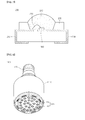
- FIG. 7 is a view showing a light emitting device package 200 including the light emitting device 100 according to the embodiment.
- the light emitting device package 200 includes a package body 205, third and fourth electrode layers 213 and 214 formed over the package body 205, the light emitting device 100 provided over the package body 205 and electrically connected to the third and fourth 213 and 214 and a molding member 240 that surrounds the light emitting device 100.
- the package body 205 may include silicon, synthetic resin or metallic material.
- An inclined surface may be formed around the light emitting device 100.
- the third and fourth electrode layers 213 and 214 are electrically isolated from each other to supply power to the light emitting device 100.
- the third and fourth electrode layers 213 and 214 reflect the light emitted from the light emitting device 100 to improve the light efficiency and dissipate heat generated from the light emitting device 100 to the outside.
- the vertical type light emitting device shown in FIG. 1 can be employed as the light emitting device 100, but the embodiment is not limited thereto.
- the light emitting device 100 can be installed over the package body 205 or the third and fourth electrode layers 213 and 214.
- the light emitting device 100 is electrically connected to the third electrode layer 213 and/or the fourth electrode layer 214 through at least one of a wire bonding scheme, a flip chip bonding scheme and a die bonding scheme. According to the embodiment, the light emitting device 100 is electrically connected to the third electrode layer 213 through a wire 230 and electrically connected to the fourth electrode layer 214 through the die bonding scheme.
- the molding member 240 surrounds the light emitting device 100 to protect the light emitting device 100.
- the molding member 240 may include phosphors to change the wavelength of the light emitted from the light emitting device 100.
- a plurality of light emitting device packages according to the embodiment may be arrayed over a substrate, and an optical member including a light guide plate, a prism sheet, a diffusion sheet or a fluorescent sheet may be provided over the optical path of the light emitted from the light emitting device package.
- the light emitting device package, the substrate, and the optical member may serve as a backlight unit or a lighting unit.
- the lighting system may include a backlight unit, a lighting unit, an indicator, a lamp or a streetlamp.
- FIG. 8 is a perspective view showing a lighting unit 1100 according to the embodiment.
- the lighting unit 1100 shown in FIG. 9 is an example of a lighting system, and the embodiment is not limited thereto.
- the lighting unit 1100 includes a case body 1110, a light emitting module 1130 installed in the case body 1110, and a connection terminal 1120 installed in the case body 1110 to receive power from an external power source.
- the case body 1110 includes material having superior heat dissipation property.
- the case body 1110 includes metallic material or resin material.
- the light emitting module 1130 may include a substrate 1132 and at least one light emitting device package 200 installed over the substrate 1132.
- the substrate 1123 includes an insulating member printed with a circuit pattern.
- the substrate 1132 includes a PCB (printed circuit board) , an MC (metal core) PCB, an F (flexible) PCB, or a ceramic PCB.
- the substrate 1132 may include material that effectively reflects the light.
- the surface of the substrate 1132 can be coated with a color, such as a white color or a silver color, to effectively reflect the light.
- At least one light emitting device package 200 can be installed over the substrate 1132.
- Each light emitting device package 200 may include at least one light emitting device 100.
- the light emitting device 100 may include a colored LED that emits the light having the color of red, green, blue or white and a UV (ultraviolet) LED that emits UV light.
- the light emitting device packages 200 of the light emitting module 1130 can be variously arranged to provide various colors and brightness.
- the white LED, the red LED and the green LED can be arranged to achieve the high color rendering index (CRI) .
- connection terminal 1120 is electrically connected to the light emitting module 1130 to supply power to the light emitting module 1130.
- the connection terminal 1120 has a shape of a socket screw-coupled with the external power source, but the embodiment is not limited thereto.
- the connection terminal 1120 can be prepared in the form of a pin inserted into the external power source or connected to the external power source through a wire.
- FIG. 9 is an exploded perspective view showing a backlight unit 1200 according to the embodiment.
- the backlight unit 1200 shown in FIG. 9 is an example of a lighting system and the embodiment is not limited thereto.
- the backlight unit 1200 includes a light guide plate 1210, a light emitting module 1240 for providing the light to the light guide plate 1210, a reflective member 1220 positioned under the light guide plate, and a bottom cover 1230 for receiving the light guide plate 1210, light emitting module 1240, and the reflective member 1220 therein, but the embodiment is not limited thereto.
- the light guide plate 1210 diffuses the light to provide surface light.
- the light guide 1210 includes transparent material.
- the light guide plate 1210 can be manufactured by using acryl-based resin, such as PMMA (polymethyl methacrylate), PET (polyethylene terephthalate), PC (polycarbonate), COC (cycloolefin copolymer) or PEN (polyethylene naphthalate) resin.
- PMMA polymethyl methacrylate
- PET polyethylene terephthalate
- PC polycarbonate
- COC cycloolefin copolymer
- PEN polyethylene naphthalate
- the light emitting module 1240 supplies the light to the lateral side of the light guide plate 1210 and serves as the light source of the display device including the backlight unit.
- the light emitting module 1240 can be positioned adjacent to the light guide plate 1210, but the embodiment is not limited thereto.
- the light emitting module 1240 includes a substrate 1242 and a plurality of light emitting device packages 200 installed over the substrate 1242 and the substrate 1242 can be adjacent to the light guide plate 1210, but the embodiment is not limited thereto.
- the substrate 1242 may include a printed circuit board (PCB) having a circuit pattern (not shown) .
- the substrate 1242 may also include a metal core PCB (MCPCB) or a flexible PCB (FPCB) in addition to the PCB, but the embodiment is not limited thereto.
- PCB printed circuit board
- MCPCB metal core PCB
- FPCB flexible PCB
- the light emitting device packages 200 are arranged such that light exit surfaces of the light emitting device packages 200 are spaced apart from the light guide plate 1210 at a predetermined distance.
- the reflective member 1220 is disposed under the light guide plate 1210.
- the reflective member 1220 reflects the light, which travels downward through the bottom surface of the light guide plate 1210, toward the light guide plate 1210, thereby improving the brightness of the backlight unit.
- the reflective member 1220 may include PET, PC or PVC resin, but the embodiment is not limited thereto.
- the bottom cover 1230 may receive the light guide plate 1210, the light emitting module 1240, and the reflective member 1220 therein. To this end, the bottom cover 1230 has a box shape with an open top surface, but the embodiment is not limited thereto.
- the bottom cover 1230 can be manufactured through a press process or an extrusion process by using metallic material or resin material.
- the light emitting device package, and the lighting system of the embodiment as the interfacial adhesion between the gallium oxide substrate and the nitride semiconductor layer is enhanced, the nitride semiconductor layer having high quality can be realized, so that a light emitting device having superior reliability and performance can be realized.
- any reference in this specification to "one embodiment,” “an embodiment,” “example embodiment,” etc. means that a particular feature, structure, or characteristic described in connection with the embodiment is included in at least one embodiment of the invention.
- the appearances of such phrases in various places in the specification are not necessarily all referring to the same embodiment.
Abstract
Description
- The embodiment relates to a light emitting device, a light emitting device package, and a lighting system.
- A light emitting device (LED) includes a p-n junction diode having a characteristic of converting electric energy into light energy. The p-n junction diode can be formed by combining group III and V elements of the periodic table. The LED can represent various colors by adjusting the compositional ratio of compound semiconductors.
- When forward voltage is applied to the LED, electrons of an n layer are bonded with holes of a p layer, so that energy corresponding to an energy gap between a conduction band and a valance band may be generated. This energy is mainly realized as heat or light, and the LED emits the energy as the light.
- A nitride semiconductor represents superior thermal stability and wide band gap energy, so the nitride semiconductor has been spotlighted in the field of optical devices and high-power electronic devices. In particular, blue, green, and UV light emitting devices employing the nitride semiconductor have already been developed and extensively used.
- Meanwhile, a light emitting device including the nitride semiconductor can be classified into a lateral type light emitting device and a vertical type light emitting device according to positions of electrode layers.
- However, the vertical type light emitting device has a difficulty in the manufacturing process because a non-conductive substrate has to be separated after the nitride semiconductor has been formed over the non-conductive substrate such as a sapphire substrate. Accordingly, researches and studies have been actively carried out toward a nitride semiconductor light emitting device that does not require the separation of a substrate by using a conductive substrate when the vertical type light emitting device is manufactured.
- For example, according to the related art, a nitride semiconductor layer may be formed over a gallium oxide substrate.
- However, according to the related art, the nitride semiconductor layer may be delaminated from the gallium oxide substrate.
- For example, the gallium oxide is easily etched at a high temperature hydrogen gas atmosphere, but the nitride semiconductor layer is grown at a high-temperature atmosphere of the mixture of ammonia gas and hydrogen gas. Therefore, when the nitride semiconductor layer is grown, a portion of the interface between the gallium oxide substrate and the nitride semiconductor layer is irregularly etched by hydrogen gas at a high temperature. The irregular etching of the interface degrades the adhesive strength of the interface, thereby causing the delamination between the nitride semiconductor layer and the gallium oxide substrate.
- In addition, the gallium oxide substrate has a thermal expansion coefficient different from that of the nitride semiconductor layer. Accordingly, when the nitride semiconductor layer is cooled after the nitride semiconductor layer has been grown, or when a heat treatment process is performed in order to manufacture the light emitting device, the delamination may be caused at the interface between the gallium oxide substrate and the nitride semiconductor layer due to the stress caused by the difference in the thermal expansion coefficient between the gallium oxide substrate and the nitride semiconductor layer.
- The embodiment provides a nitride semiconductor light emitting device capable of representing high performance by realizing a high-quality nitride semiconductor layer over a gallium oxide substrate, a light emitting device package, and a lighting system.
- According to the embodiment, a light emitting device includes an oxide including gallium aluminum over a gallium oxide substrate, a nitride including gallium aluminum over the oxide including gallium aluminum, and a light emitting structure over the nitride including gallium aluminum.
- According to the embodiment, the light emitting device package includes a package body, third and fourth electrode layers installed over the package body, and a light emitting device electrically connected to the third and fourth electrode layers.
- According to the embodiment, the lighting system includes a substrate, and a light emitting module including a light emitting device package installed over the substrate. The light emitting device package includes a package body, third and fourth electrode layers installed over the package body, and a lighting emitting device according to claim 1 and electrically connected to the third and fourth electrode layers.
-
-
FIG. 1 is a sectional view showing a light emitting device according to the embodiment; -
FIGS. 2 to 6 are sectional views showing a method of manufacturing the light emitting device according to the embodiment; -
FIG. 7 is a sectional view showing a light emitting device package according to the embodiment; -
FIG. 8 is a perspective view showing a lighting unit according to the embodiment; and -
FIG. 9 is an exploded perspective view showing a backlight unit according to the embodiment. - Hereinafter, a light emitting device, a light emitting device package, and a lighting system according to the embodiment will be described with reference to accompanying drawings.
- In the description of embodiments, it will be understood that when a layer (or film) is referred to as being 'on' another layer or substrate, it can be directly over another layer or substrate, or intervening layers may also be present. Further, it will be understood that when a layer is referred to as being 'under' another layer, it can be directly under another layer, and one or more intervening layers may also be present. In addition, it will also be understood that when a layer is referred to as being 'between' two layers, it can be the only layer between the two layers, or one or more intervening layers may also be present.
-
FIG. 1 is a sectional view showing alight emitting device 100 according to the embodiment. - The
light emitting device 100 may include agallium aluminum oxide 110 over agallium oxide substrate 105, agallium aluminum nitride 120 over thegallium aluminum oxide 110, and alight emitting structure 130 over thegallium aluminum nitride 120. - The
gallium aluminum oxide 110 may include GaxAlyOz (0 〈 x≤1, 0 〈y≤1,0 〈z≤1), but the embodiment is not limited thereto. - The
gallium aluminum nitride 120 may include GaxAlyNz (0 〈x≤1, 0 〈y≤1,0 〈z≤1), but the embodiment is not limited thereto. - The
light emitting structure 130 may include a secondconductive semiconductor layer 132 over thegallium aluminum nitride 120, anactive layer 134 over the secondconductive semiconductor layer 132, and a firstconductive semiconductor layer 136 over theactive layer 134, but the embodiment is not limited thereto. - According to the embodiment, the bond strength between gallium (Ga) and oxygen (O) is stronger than the bond strength between aluminum (Al) and oxygen (O), and the bond strength between gallium (Ga) and nitrogen (N) is stronger than the bond strength between aluminum (Al) and nitrogen (N).
- Accordingly, the interfacial adhesion between the
gallium aluminum oxide 110 and thegallium aluminum nitride 120 is stronger than that between the gallium oxide substrate and thelight emitting structure 130 including a nitride semiconductor layer. Accordingly, thelight emitting structure 130 can be prevented from being delaminated from thegallium oxide substrate 105. The interfacial adhesion between thegallium aluminum oxide 110 and thegallium aluminum nitride 120 is stronger than that between gallium oxide/gallium nitride and the nitride semiconductor layer, so that delamination can be prevented. - According to the light emitting device and a method of manufacturing the same according to the embodiment, as the interfacial adhesion between the gallium oxide substrate and the nitride semiconductor layer is enhanced, the nitride semiconductor layer having high quality can be realized, so that a light emitting device having superior reliability and performance can be realized.
- Hereinafter, the method of manufacturing the
light emitting device 100 according to the embodiment will be described with reference toFIGS. 2 to 6 . - As shown in
FIG. 2 , thegallium oxide substrate 105 is prepared. Thegallium oxide substrate 105 may include a conductive substrate. Thegallium oxide substrate 105 may include a Ga203 substrate, but the embodiment is not limited thereto. - The
gallium oxide substrate 105 may have superior electrical conductivity through the doping of impurities. - A wet cleaning process is performed with respect to the
gallium oxide substrate 105 to remove organic and inorganic materials from thegallium oxide substrate 105. - As shown in
FIG. 3 , thegallium aluminum oxide 110 is formed over thegallium oxide substrate 105. Thegallium aluminum oxide 110 may include GaxAlyOz(0 (x≤1, 0 〈y≤1,0 〈z≤1), but the embodiment is not limited thereto. - Since the bond strength between atoms is strongly represented in the
gallium aluminum oxide 110, great energy gap is represented. Accordingly, since thegallium aluminum oxide 110 may have electrical conductivity less than that of thegallium oxide substrate 105, thegallium aluminum oxide 110 may be formed at a thickness of 1 µm or less, but the embodiment is not limited thereto. - In order to form the
gallium aluminum oxide 110, a deposition process may be performed with respect to the top surface of thegallium oxide substrate 105 by using a thin film deposition device. For example, thegallium aluminum oxide 110 may be formed through liquid-phase epitaxy, vapor phase epitaxy, molecular beam epitaxy, or sputtering. - In order to form the
gallium aluminum oxide 110, an aluminum layer (not shown) is formed over thegallium oxide substrate 105. Thereafter, heat treatment is performed with respect to the resultant structure at an oxygen atmosphere, so that Al atoms of the aluminum layer are diffused into thegallium oxide substrate 105, thereby forming thegallium aluminum oxide 110. - For example, after an Al thin film layer has been formed over the
gallium oxide substrate 105, oxygen gas or mixture gas mainly containing oxygen gas is injected into a chamber and heat treatment is performed with respect to thegallium oxide substrate 105 at a temperature of about 500 °C to 1200°C, thereby forming thegallium aluminum oxide 110. However, the embodiment is not limited thereto. - Thereafter, as shown in
FIG. 4 , thegallium aluminum nitride 120 is formed over thegallium aluminum oxide 110. - The
gallium aluminum nitride 120 may include GaxAlyNz (0〈x≤1, 0 〈y≤1,0 〈z≤1), but the embodiment is not limited thereto. - The
gallium aluminum nitride 120 may be formed over thegallium aluminum oxide 110 by using a thin film deposition device. For example, thegallium aluminum nitride 120 may be formed through liquid-phase epitaxy, vapor phase epitaxy, molecular beam epitaxy, or sputtering, but the embodiment is not limited thereto. - The
gallium aluminum nitride 120 may be formed by nitrifying a portion of thegallium aluminum oxide 110. - For example, an aluminum layer (not shown) is formed over the
gallium oxide substrate 105. Thereafter, heat treatment is performed with respect to the resultant structure at an oxygen atmosphere, so that Al atoms of the aluminum layer are diffused into thegallium oxide substrate 105, thereby forming thegallium aluminum oxide 110. Next, thegallium aluminum oxide 110 is nitrified at a high temperature and at an ammonia atmosphere, so that thegallium aluminum nitride 120 can be formed. - The high-temperature nitrification can be performed by injecting ammonia gas, the mixture of ammonia gas and oxygen gas, or the mixture of ammonia gas and nitrogen gas into a chamber.
- In this case, impurity gas is injected into the chamber, so that the electrical conductivity of the
gallium aluminum nitride 120 can be improved. - According to the embodiment, the bond strength between gallium (Ga) and oxygen (O) is stronger than that between aluminum (Al) and oxygen (O), and the bond strength between gallium (Ga) and nitrogen (N) is stronger than that between aluminum (Al) and nitrogen (N).
- Accordingly, the interfacial adhesion between the
gallium aluminum oxide 110 and thegallium aluminum nitride 120 is stronger than that between thegallium oxide substrate 105 and thelight emitting structure 130 including a nitride semiconductor layer. Therefore, the delamination between thegallium oxide substrate 105 and thelight emitting structure 130 can be prevented. - According to the light emitting device and the method of manufacturing the same according to the embodiment, as the interfacial adhesion between the gallium oxide substrate and the nitride semiconductor layer is enhanced, the nitride semiconductor layer having high quality can be realized, so that a light emitting device having superior reliability and performance can be realized.
- Then, the
light emitting structure 130 may be formed over thegallium aluminum nitride 120 as shown inFIG. 5. FIG. 6 is an enlarged view showing a portion of thelight emitting structure 130. - The
light emitting structure 130 may include the secondconductive semiconductor layer 132 formed over thegallium aluminum nitride 120, theactive layer 134 formed over the secondconductive semiconductor layer 132, and the firstconductive semiconductor layer 136 formed over theactive layer 134, but the embodiment is not limited thereto. - The first
conductive semiconductor layer 136 may include group III-V compound semiconductors doped with first conductive dopants. When the firstconductive semiconductor layer 136 is an N type semiconductor layer, the first conductive dopants may include Si, Ge, Sn, Se, or Te as N type dopants, but the embodiment is not limited thereto. - The first
conductive semiconductor layer 136 may include a semiconductor material having a composition formula of InxAlyGa1-x-yN (0≤x≤1, 0≤y≤1, 0≤x+y≤1) . - The first
conductive semiconductor layer 136 may include at least one selected from the group consisting of InN, AIN, InGaN, AlGaN, InAlGaN, AlInN, AlGaAs, InGaAs, AlInGaAs, GaP, AlGaP, InGaP, AlInGaP, and InP. - The first
conductive semiconductor layer 136 may include an N type GaN layer through CVD (chemical vapor deposition), MBE (molecular beam epitaxy), sputtering, or HVPE (hydride vapor phase epitaxy) . In addition, the firstconductive semiconductor layer 136 may be formed by injecting trimethyl gallium (TMGa) gas, ammonia (NH3) gas, nitrogen (N2) gas, or silane (SiH4) gas including N type impurities such as Si into a chamber. - The
active layer 134 emits a light having energy determined by an intrinsic energy band of materials constituting the active layer (light emitting layer) through the combination of electrons injected through the firstconductive semiconductor layer 136 and holes injected through the secondconductive semiconductor layer 132. - The
active layer 134 may have one of a SQW (single quantum well) structure, an MQW (multi-quantum well) structure, a quantum-wire structure, or a quantum dot structure. For example, theactive layer 134 may have the MQW structure by injecting TMGa gas, NH3 gas, N2 gas or TMIn gas, but the embodiment is not limited thereto. - The
active layer 134 may have a well/barrier layer including at least one of InGaN/GaN, InGaN/InGaN, GaN/AlGaN, InAlGaN/GaN, GaAs (InGaAs)/AlGaAs and GaP (InGaP)/AlGaP, but the embodiment is not limited thereto. The well layer may include a material having the band gap energy lower than that of the barrier layer. - A conductive clad layer (not shown) can be formed over and/or under the
active layer 134. The conductive clad layer may include an AlGaN-based semiconductor having the band gap energy higher than that of theactive layer 134. - The second
conductive semiconductor layer 132 may include the group III-V compound semiconductor doped with the second conductive dopant. For instance, the secondconductive semiconductor layer 132 may include the semiconductor material having the composition formula of InxAlyGa1-x-yN (0≤x≤1, 0≤y≤1, 0≤x+y≤1) . In detail, the secondconductive semiconductor layer 132 may include one selected from the group consisting of GaN, AIN, AlGaN, InGaN, InN, InAlGaN, AlInN, AlGaAs, GaP, GaAs, GaAsP, and AlGaInP. If the secondconductive semiconductor layer 132 is a P type semiconductor layer, the second conductive dopant includes the P type dopant such as Mg, Zn, Ca, Sr, or Ba. The secondconductive semiconductor layer 132 can be prepared as a single layer or a multiple layer, but the embodiment is not limited thereto. - The second
conductive semiconductor layer 132 may include a P type GaN layer, which can be formed by injecting TMGa gas, NH3 gas, N2 gas and (EtCp2Mg) {Mg (C2H5C5H4)2} gas including p type impurities (for example, Mg) into the chamber, but the embodiment is not limited thereto. - According to the embodiment, the first
conductive semiconductor layer 136 may include an N type semiconductor layer and the secondconductive semiconductor layer 136 may include a P type semiconductor layer. The firstconductive semiconductor layer 136 may include a P type semiconductor layer and the secondconductive semiconductor layer 136 may include an N type semiconductor layer. - In addition, a semiconductor layer, such as an N type semiconductor layer (not shown) having polarity opposite to that of the second
conductive semiconductor layer 132, can be formed over the secondconductive semiconductor layer 132. Thus, thelight emitting structure 130 may include one of an N-P junction structure, a P-N junction structure, an N-P-N junction structure, and a P-N-P junction structure. - Thereafter, a second electrode (not shown) may be formed under the
gallium oxide substrate 105, and a first electrode (not shown) may be formed over the firstconductive semiconductor layer 136. - The second electrode may include an ohmic layer (not shown), a reflective layer (not shown), or a conductive support substrate (not shown).
- For example, the second electrode may include an ohmic layer, and may have a multi-stack structure of single metal, metallic alloy, or metallic oxide such that hole injection can be efficiently performed.
- For example, the ohmic layer may include at least one selected from the group consisting of ITO (indium tin oxide), IZO (indium zinc oxide), IZTO (indium zinc tin oxide), IAZO (indium aluminum zinc oxide), IGZO (indium gallium zinc oxide), IGTO (indium gallium tin oxide), AZO (aluminum zinc oxide), ATO (antimony tin oxide), GZO (gallium zinc oxide), IZON (IZO Nitride), AGZO (Al-Ga ZnO), IGZO (In-Ga ZnO), ZnO, IrOx, RuOx, NiO, RuOx/ITO, Ni/IrOx/Au, Ni/IrOx/Au/ITO, Ag, Ni, Cr, Ti, Al, Rh, Pd, Ir, Ru, Mg, Zn, Pt, Au, and Hf, but the embodiment is not limited thereto.
- For example, the reflective layer may include a metal or a metal alloy including at least one selected from the group consisting of Ag, Ni, Al, Rh, Pd, Ir, Ru, Mg, Zn, Pt, Au, and Hf. In addition, the reflective layer can be prepared as a multiple layer by using the above metal or metal alloy and transmissive conductive material, such as IZO, IZTO, IAZO, IGZO, IGTO, AZO, or ATO. For instance, the reflective layer may have the stack structure including IZ0/Ni, AZO/Ag, IZO/Ag/Ni, AZO/Ag/Ni.
- In addition, a conductive support substrate may include at least one selected from the group consisting of copper (Cu), a Cu alloy, gold (Au), nickel (Ni), molybdenum (Mo), copper-tungsten (Cu-W), and a carrier wafer (for example, Si, Ge, GaAs, GaN, ZnO, SiGe, or SiC wafer).
- According to the light emitting device of the embodiment, as the interfacial adhesion between the gallium oxide substrate and the nitride semiconductor layer is enhanced, the nitride semiconductor layer having high quality can be realized, so that a light emitting device having superior reliability and performance can be realized.
-
FIG. 7 is a view showing a light emittingdevice package 200 including thelight emitting device 100 according to the embodiment. - Referring to
FIG. 7 , the light emittingdevice package 200 according to the embodiment includes apackage body 205, third and fourth electrode layers 213 and 214 formed over thepackage body 205, thelight emitting device 100 provided over thepackage body 205 and electrically connected to the third and fourth 213 and 214 and amolding member 240 that surrounds thelight emitting device 100. - The
package body 205 may include silicon, synthetic resin or metallic material. An inclined surface may be formed around thelight emitting device 100. - The third and fourth electrode layers 213 and 214 are electrically isolated from each other to supply power to the
light emitting device 100. In addition, the third and fourth electrode layers 213 and 214 reflect the light emitted from thelight emitting device 100 to improve the light efficiency and dissipate heat generated from thelight emitting device 100 to the outside. - The vertical type light emitting device shown in
FIG. 1 can be employed as thelight emitting device 100, but the embodiment is not limited thereto. - The
light emitting device 100 can be installed over thepackage body 205 or the third and fourth electrode layers 213 and 214. - The
light emitting device 100 is electrically connected to thethird electrode layer 213 and/or thefourth electrode layer 214 through at least one of a wire bonding scheme, a flip chip bonding scheme and a die bonding scheme. According to the embodiment, thelight emitting device 100 is electrically connected to thethird electrode layer 213 through awire 230 and electrically connected to thefourth electrode layer 214 through the die bonding scheme. - The
molding member 240 surrounds thelight emitting device 100 to protect thelight emitting device 100. In addition, themolding member 240 may include phosphors to change the wavelength of the light emitted from thelight emitting device 100. - A plurality of light emitting device packages according to the embodiment may be arrayed over a substrate, and an optical member including a light guide plate, a prism sheet, a diffusion sheet or a fluorescent sheet may be provided over the optical path of the light emitted from the light emitting device package. The light emitting device package, the substrate, and the optical member may serve as a backlight unit or a lighting unit. For example, the lighting system may include a backlight unit, a lighting unit, an indicator, a lamp or a streetlamp.
-
FIG. 8 is a perspective view showing alighting unit 1100 according to the embodiment. Thelighting unit 1100 shown inFIG. 9 is an example of a lighting system, and the embodiment is not limited thereto. - Referring to
FIG. 8 , thelighting unit 1100 includes acase body 1110, alight emitting module 1130 installed in thecase body 1110, and aconnection terminal 1120 installed in thecase body 1110 to receive power from an external power source. - Preferably, the
case body 1110 includes material having superior heat dissipation property. For example, thecase body 1110 includes metallic material or resin material. - The
light emitting module 1130 may include asubstrate 1132 and at least one light emittingdevice package 200 installed over thesubstrate 1132. - The substrate 1123 includes an insulating member printed with a circuit pattern. For instance, the
substrate 1132 includes a PCB (printed circuit board) , an MC (metal core) PCB, an F (flexible) PCB, or a ceramic PCB. - In addition, the
substrate 1132 may include material that effectively reflects the light. The surface of thesubstrate 1132 can be coated with a color, such as a white color or a silver color, to effectively reflect the light. - At least one light emitting
device package 200 can be installed over thesubstrate 1132. Each light emittingdevice package 200 may include at least one light emittingdevice 100. Thelight emitting device 100 may include a colored LED that emits the light having the color of red, green, blue or white and a UV (ultraviolet) LED that emits UV light. - The light emitting device packages 200 of the
light emitting module 1130 can be variously arranged to provide various colors and brightness. For example, the white LED, the red LED and the green LED can be arranged to achieve the high color rendering index (CRI) . - The
connection terminal 1120 is electrically connected to thelight emitting module 1130 to supply power to thelight emitting module 1130. Theconnection terminal 1120 has a shape of a socket screw-coupled with the external power source, but the embodiment is not limited thereto. For example, theconnection terminal 1120 can be prepared in the form of a pin inserted into the external power source or connected to the external power source through a wire. -
FIG. 9 is an exploded perspective view showing abacklight unit 1200 according to the embodiment. Thebacklight unit 1200 shown inFIG. 9 is an example of a lighting system and the embodiment is not limited thereto. - The
backlight unit 1200 according to the embodiment includes alight guide plate 1210, alight emitting module 1240 for providing the light to thelight guide plate 1210, areflective member 1220 positioned under the light guide plate, and abottom cover 1230 for receiving thelight guide plate 1210, light emittingmodule 1240, and thereflective member 1220 therein, but the embodiment is not limited thereto. - The
light guide plate 1210 diffuses the light to provide surface light. Thelight guide 1210 includes transparent material. For example, thelight guide plate 1210 can be manufactured by using acryl-based resin, such as PMMA (polymethyl methacrylate), PET (polyethylene terephthalate), PC (polycarbonate), COC (cycloolefin copolymer) or PEN (polyethylene naphthalate) resin. - The
light emitting module 1240 supplies the light to the lateral side of thelight guide plate 1210 and serves as the light source of the display device including the backlight unit. - The
light emitting module 1240 can be positioned adjacent to thelight guide plate 1210, but the embodiment is not limited thereto. In detail, thelight emitting module 1240 includes asubstrate 1242 and a plurality of light emitting device packages 200 installed over thesubstrate 1242 and thesubstrate 1242 can be adjacent to thelight guide plate 1210, but the embodiment is not limited thereto. - The
substrate 1242 may include a printed circuit board (PCB) having a circuit pattern (not shown) . In addition, thesubstrate 1242 may also include a metal core PCB (MCPCB) or a flexible PCB (FPCB) in addition to the PCB, but the embodiment is not limited thereto. - In addition, the light emitting device packages 200 are arranged such that light exit surfaces of the light emitting device packages 200 are spaced apart from the
light guide plate 1210 at a predetermined distance. - The
reflective member 1220 is disposed under thelight guide plate 1210. Thereflective member 1220 reflects the light, which travels downward through the bottom surface of thelight guide plate 1210, toward thelight guide plate 1210, thereby improving the brightness of the backlight unit. For example, thereflective member 1220 may include PET, PC or PVC resin, but the embodiment is not limited thereto. - The
bottom cover 1230 may receive thelight guide plate 1210, thelight emitting module 1240, and thereflective member 1220 therein. To this end, thebottom cover 1230 has a box shape with an open top surface, but the embodiment is not limited thereto. - The
bottom cover 1230 can be manufactured through a press process or an extrusion process by using metallic material or resin material. - According to the light emitting device, the light emitting device package, and the lighting system of the embodiment, as the interfacial adhesion between the gallium oxide substrate and the nitride semiconductor layer is enhanced, the nitride semiconductor layer having high quality can be realized, so that a light emitting device having superior reliability and performance can be realized.
- Any reference in this specification to "one embodiment," "an embodiment," "example embodiment," etc., means that a particular feature, structure, or characteristic described in connection with the embodiment is included in at least one embodiment of the invention. The appearances of such phrases in various places in the specification are not necessarily all referring to the same embodiment. Further, when a particular feature, structure, or characteristic is described in connection with any embodiment, it is submitted that it is within the purview of one skilled in the art to effect such feature, structure, or characteristic in connection with other ones of the embodiments.
- Although embodiments have been described with reference to a number of illustrative embodiments thereof, it should be understood that numerous other modifications and embodiments can be devised by those skilled in the art that will fall within the spirit and scope of the principles of this disclosure. More particularly, various variations and modifications are possible in the component parts and/or arrangements of the subject combination arrangement within the scope of the disclosure, the drawings and the appended claims. In addition to variations and modifications in the component parts and/or arrangements, alternative uses will also be apparent to those skilled in the art.
Claims (7)
- A light emitting device comprising:an oxide including gallium aluminum over a gallium oxide substrate;a nitride including gallium aluminum over the oxide including gallium aluminum; anda light emitting structure over the nitride including gallium aluminum.
- The light emitting device of claim 1, wherein the oxide including gallium aluminum comprises GaxAlyOz (0 〈x≤1, 0 〈y≤1, 0 〈z≤1) .
- The light emitting device of claim 1, wherein the oxide including gallium aluminum has a thickness of 1 µm or less.
- The light emitting device of claim 1, wherein the nitride including gallium aluminum comprises GaxAlyNz, (0 〈x≤1, 0 〈y≤1, 0 〈z≤1)
- The light emitting device of claim 1, wherein the light emitting structure comprises:a second conductive semiconductor layer over the nitride including gallium aluminum;an active layer over the second conductive semiconductor layer; anda first conductive semiconductor layer over the active layer.
- A light emitting device package comprising:a package body;third and fourth electrode layers over the package body; anda light emitting device according to one of claims 1 ~5 and electrically connected to the third and fourth electrode layers.
- A lighting system comprising:a substrate; anda light emitting module including a light emitting device package over the substrate,wherein the light emitting device package comprises a package body, third and fourth electrode layers over the package body, and a lighting emitting device according to one of claims 1-5 and electrically connected to the third and fourth electrode layers.
Applications Claiming Priority (1)
| Application Number | Priority Date | Filing Date | Title |
|---|---|---|---|
| KR1020090127189A KR101047652B1 (en) | 2009-12-18 | 2009-12-18 | Light emitting device and manufacturing method |
Publications (2)
| Publication Number | Publication Date |
|---|---|
| EP2337093A1 true EP2337093A1 (en) | 2011-06-22 |
| EP2337093B1 EP2337093B1 (en) | 2013-01-02 |
Family
ID=43589886
Family Applications (1)
| Application Number | Title | Priority Date | Filing Date |
|---|---|---|---|
| EP10191489A Active EP2337093B1 (en) | 2009-12-18 | 2010-11-17 | Light emitting device, light emitting device package and lighting system |
Country Status (5)
| Country | Link |
|---|---|
| US (3) | US8115230B2 (en) |
| EP (1) | EP2337093B1 (en) |
| JP (1) | JP5751696B2 (en) |
| KR (1) | KR101047652B1 (en) |
| CN (1) | CN102104093B (en) |
Cited By (1)
| Publication number | Priority date | Publication date | Assignee | Title |
|---|---|---|---|---|
| WO2019180513A1 (en) * | 2018-03-19 | 2019-09-26 | King Abdullah University Of Science And Technology | Iii-nitride optoelectronic devices and method of production |
Families Citing this family (7)
| Publication number | Priority date | Publication date | Assignee | Title |
|---|---|---|---|---|
| CN103781947B (en) * | 2011-09-08 | 2019-05-10 | 株式会社田村制作所 | Crystal laminate structure |
| JP5343224B1 (en) * | 2012-09-28 | 2013-11-13 | Roca株式会社 | Semiconductor device and crystal |
| JP2016015375A (en) * | 2014-07-01 | 2016-01-28 | 株式会社タムラ製作所 | Light emitting element |
| KR102457424B1 (en) * | 2014-10-27 | 2022-10-24 | 다우 글로벌 테크놀로지스 엘엘씨 | Plasticizer compositions and methods for making plasticizer compositions |
| JP6776931B2 (en) * | 2016-03-23 | 2020-10-28 | 三菱マテリアル株式会社 | Manufacturing method of laminated reflective electrode film, laminated reflective electrode pattern, laminated reflective electrode pattern |
| TWI577842B (en) * | 2016-05-30 | 2017-04-11 | 光鋐科技股份有限公司 | Growth method of aluminum gallium nitride |
| CN107358780B (en) * | 2017-07-30 | 2020-01-03 | 王旭兰 | Intelligent electric spark detection alarm system based on PN junction chip and preparation method thereof |
Citations (4)
| Publication number | Priority date | Publication date | Assignee | Title |
|---|---|---|---|---|
| EP1653502A1 (en) * | 2003-08-08 | 2006-05-03 | Koha Co., Ltd. | Semiconductor layer |
| US20060223287A1 (en) * | 2005-03-31 | 2006-10-05 | Toyoda Gosei Co., Ltd | Method of forming a low temperature-grown buffer layer, light emitting element, method of making same, and light emitting device |
| US20080142795A1 (en) * | 2004-03-12 | 2008-06-19 | Waseda University | Ga2o3 Semiconductor Device |
| JP2009091217A (en) * | 2007-10-11 | 2009-04-30 | Nippon Light Metal Co Ltd | Gallium-aluminum oxide crystal film, method of manufacturing the same and semiconductor device using the same |
Family Cites Families (24)
| Publication number | Priority date | Publication date | Assignee | Title |
|---|---|---|---|---|
| JP3679097B2 (en) * | 2002-05-31 | 2005-08-03 | 株式会社光波 | Light emitting element |
| TWI303909B (en) * | 2002-11-25 | 2008-12-01 | Nichia Corp | Ridge waveguide semiconductor laser diode |
| JP3728305B2 (en) * | 2003-08-20 | 2005-12-21 | ▲さん▼圓光電股▲ふん▼有限公司 | Light emitting diode device using selective growth |
| TW200520266A (en) * | 2003-11-21 | 2005-06-16 | Sanken Electric Co Ltd | Semiconductor luminous element and manufacturing method of the same |
| US7369583B2 (en) * | 2004-06-07 | 2008-05-06 | Innolume Gmbh | Electrooptically wavelength-tunable resonant cavity optoelectronic device for high-speed data transfer |
| JP4624131B2 (en) * | 2005-02-22 | 2011-02-02 | 三洋電機株式会社 | Nitride semiconductor device manufacturing method |
| KR100593937B1 (en) * | 2005-03-30 | 2006-06-30 | 삼성전기주식회사 | Led package using si substrate and fabricating method thereof |
| KR100691159B1 (en) * | 2005-04-30 | 2007-03-09 | 삼성전기주식회사 | Method For Manufacturing Gallium Nitride-Based Semiconductor Device |
| US8008215B2 (en) * | 2005-05-12 | 2011-08-30 | Massachusetts Institute Of Technology | Integration of buried oxide layers with crystalline layers |
| JP4225510B2 (en) * | 2005-07-06 | 2009-02-18 | 昭和電工株式会社 | Compound semiconductor light emitting diode and method for manufacturing the same |
| JP3998027B2 (en) * | 2005-07-25 | 2007-10-24 | 松下電工株式会社 | Lighting equipment using LED |
| JP5180430B2 (en) * | 2005-08-04 | 2013-04-10 | 独立行政法人物質・材料研究機構 | Light emitting element |
| US20070134833A1 (en) * | 2005-12-14 | 2007-06-14 | Toyoda Gosei Co., Ltd. | Semiconductor element and method of making same |
| JP2007234902A (en) * | 2006-03-01 | 2007-09-13 | Toyoda Gosei Co Ltd | Light-emitting element, and manufacturing method thereof |
| JP2007165626A (en) * | 2005-12-14 | 2007-06-28 | Toyoda Gosei Co Ltd | Light emitting element and its manufacturing method |
| WO2007072919A1 (en) * | 2005-12-22 | 2007-06-28 | Matsushita Electric Works, Ltd. | Illumination instrument using led |
| KR100795547B1 (en) | 2006-06-30 | 2008-01-21 | 서울옵토디바이스주식회사 | A light emitting device of a nitride conpound seniconductor |
| KR101321935B1 (en) * | 2006-12-01 | 2013-10-25 | 서울바이오시스 주식회사 | A light emitting diode of a nitride compound and fabricating method therefor |
| KR100915502B1 (en) | 2007-01-18 | 2009-09-03 | 광주과학기술원 | Light-Emitting Diode using Surface Plasmon |
| JP2008258042A (en) * | 2007-04-06 | 2008-10-23 | Hitachi Displays Ltd | Illumination device and display device using this illumination device |
| JP2009060005A (en) * | 2007-09-03 | 2009-03-19 | Nippon Light Metal Co Ltd | Light emitting device and method of manufacturing the same |
| TWI362765B (en) * | 2007-09-07 | 2012-04-21 | Epistar Corp | Light emitting diode device and manufacturing method therof |
| KR100998007B1 (en) | 2007-11-23 | 2010-12-03 | 삼성엘이디 주식회사 | Nitride semiconductor light emitting device |
| WO2011155302A1 (en) * | 2010-06-11 | 2011-12-15 | Semiconductor Energy Laboratory Co., Ltd. | Semiconductor device |
-
2009
- 2009-12-18 KR KR1020090127189A patent/KR101047652B1/en not_active IP Right Cessation
-
2010
- 2010-11-05 US US12/940,718 patent/US8115230B2/en active Active
- 2010-11-17 EP EP10191489A patent/EP2337093B1/en active Active
- 2010-12-03 CN CN201010579308.8A patent/CN102104093B/en active Active
- 2010-12-13 JP JP2010277127A patent/JP5751696B2/en active Active
-
2012
- 2012-01-12 US US13/349,387 patent/US8349743B2/en active Active
-
2013
- 2013-01-07 US US13/735,607 patent/US9099611B2/en active Active
Patent Citations (4)
| Publication number | Priority date | Publication date | Assignee | Title |
|---|---|---|---|---|
| EP1653502A1 (en) * | 2003-08-08 | 2006-05-03 | Koha Co., Ltd. | Semiconductor layer |
| US20080142795A1 (en) * | 2004-03-12 | 2008-06-19 | Waseda University | Ga2o3 Semiconductor Device |
| US20060223287A1 (en) * | 2005-03-31 | 2006-10-05 | Toyoda Gosei Co., Ltd | Method of forming a low temperature-grown buffer layer, light emitting element, method of making same, and light emitting device |
| JP2009091217A (en) * | 2007-10-11 | 2009-04-30 | Nippon Light Metal Co Ltd | Gallium-aluminum oxide crystal film, method of manufacturing the same and semiconductor device using the same |
Cited By (1)
| Publication number | Priority date | Publication date | Assignee | Title |
|---|---|---|---|---|
| WO2019180513A1 (en) * | 2018-03-19 | 2019-09-26 | King Abdullah University Of Science And Technology | Iii-nitride optoelectronic devices and method of production |
Also Published As
| Publication number | Publication date |
|---|---|
| KR20110070382A (en) | 2011-06-24 |
| JP2011129915A (en) | 2011-06-30 |
| US20130119402A1 (en) | 2013-05-16 |
| EP2337093B1 (en) | 2013-01-02 |
| CN102104093B (en) | 2015-06-17 |
| JP5751696B2 (en) | 2015-07-22 |
| US8349743B2 (en) | 2013-01-08 |
| KR101047652B1 (en) | 2011-07-07 |
| US20110147771A1 (en) | 2011-06-23 |
| CN102104093A (en) | 2011-06-22 |
| US8115230B2 (en) | 2012-02-14 |
| US9099611B2 (en) | 2015-08-04 |
| US20120115267A1 (en) | 2012-05-10 |
Similar Documents
| Publication | Publication Date | Title |
|---|---|---|
| US8421110B2 (en) | Light emitting device and light emitting device package | |
| EP2482343B1 (en) | Semiconductor based light emitting diode | |
| US9099611B2 (en) | Light emitting device | |
| US9287460B2 (en) | Light emitting device, light emitting device package and lighting system including the same | |
| US8519418B2 (en) | Light emitting device package having dielectric pattern on reflective layer | |
| US8669586B2 (en) | Light emitting device, light emitting device package, and lighting system | |
| EP2355190A2 (en) | Passivated light emitting device | |
| US8436383B2 (en) | Light emitting device, light emitting device package, and lighting system | |
| EP2341562A1 (en) | Light emitting device | |
| EP2296196B1 (en) | Light emitting device | |
| EP2315272B1 (en) | Light emitting diode, light emitting diode package, and lighting system | |
| US20130001617A1 (en) | Light emitting device | |
| US8692278B2 (en) | Light emitting device | |
| KR101880451B1 (en) | Light emitting device | |
| KR20120015882A (en) | Light emitting device package |
Legal Events
| Date | Code | Title | Description |
|---|---|---|---|
| PUAI | Public reference made under article 153(3) epc to a published international application that has entered the european phase |
Free format text: ORIGINAL CODE: 0009012 |
|
| 17P | Request for examination filed |
Effective date: 20101117 |
|
| AK | Designated contracting states |
Kind code of ref document: A1 Designated state(s): AL AT BE BG CH CY CZ DE DK EE ES FI FR GB GR HR HU IE IS IT LI LT LU LV MC MK MT NL NO PL PT RO RS SE SI SK SM TR |
|
| AX | Request for extension of the european patent |
Extension state: BA ME |
|
| REG | Reference to a national code |
Ref country code: DE Ref legal event code: R079 Ref document number: 602010004420 Country of ref document: DE Free format text: PREVIOUS MAIN CLASS: H01L0033000000 Ipc: H01L0033120000 |
|
| RIC1 | Information provided on ipc code assigned before grant |
Ipc: H01L 33/00 20100101ALI20120712BHEP Ipc: H01L 21/02 20060101AFI20120712BHEP |
|
| RIC1 | Information provided on ipc code assigned before grant |
Ipc: H01L 21/02 20060101ALI20120806BHEP Ipc: H01L 33/00 20100101ALI20120806BHEP Ipc: H01L 33/12 20100101AFI20120806BHEP |
|
| GRAP | Despatch of communication of intention to grant a patent |
Free format text: ORIGINAL CODE: EPIDOSNIGR1 |
|
| GRAS | Grant fee paid |
Free format text: ORIGINAL CODE: EPIDOSNIGR3 |
|
| GRAA | (expected) grant |
Free format text: ORIGINAL CODE: 0009210 |
|
| AK | Designated contracting states |
Kind code of ref document: B1 Designated state(s): AL AT BE BG CH CY CZ DE DK EE ES FI FR GB GR HR HU IE IS IT LI LT LU LV MC MK MT NL NO PL PT RO RS SE SI SK SM TR |
|
| REG | Reference to a national code |
Ref country code: GB Ref legal event code: FG4D |
|
| REG | Reference to a national code |
Ref country code: AT Ref legal event code: REF Ref document number: 592030 Country of ref document: AT Kind code of ref document: T Effective date: 20130115 Ref country code: CH Ref legal event code: EP |
|
| REG | Reference to a national code |
Ref country code: IE Ref legal event code: FG4D |
|
| REG | Reference to a national code |
Ref country code: DE Ref legal event code: R096 Ref document number: 602010004420 Country of ref document: DE Effective date: 20130307 |
|
| REG | Reference to a national code |
Ref country code: NL Ref legal event code: T3 |
|
| REG | Reference to a national code |
Ref country code: AT Ref legal event code: MK05 Ref document number: 592030 Country of ref document: AT Kind code of ref document: T Effective date: 20130102 |
|
| PG25 | Lapsed in a contracting state [announced via postgrant information from national office to epo] |
Ref country code: SI Free format text: LAPSE BECAUSE OF FAILURE TO SUBMIT A TRANSLATION OF THE DESCRIPTION OR TO PAY THE FEE WITHIN THE PRESCRIBED TIME-LIMIT Effective date: 20130102 |
|
| REG | Reference to a national code |
Ref country code: LT Ref legal event code: MG4D |
|
| PG25 | Lapsed in a contracting state [announced via postgrant information from national office to epo] |
Ref country code: ES Free format text: LAPSE BECAUSE OF FAILURE TO SUBMIT A TRANSLATION OF THE DESCRIPTION OR TO PAY THE FEE WITHIN THE PRESCRIBED TIME-LIMIT Effective date: 20130413 Ref country code: IS Free format text: LAPSE BECAUSE OF FAILURE TO SUBMIT A TRANSLATION OF THE DESCRIPTION OR TO PAY THE FEE WITHIN THE PRESCRIBED TIME-LIMIT Effective date: 20130502 Ref country code: BG Free format text: LAPSE BECAUSE OF FAILURE TO SUBMIT A TRANSLATION OF THE DESCRIPTION OR TO PAY THE FEE WITHIN THE PRESCRIBED TIME-LIMIT Effective date: 20130402 Ref country code: NO Free format text: LAPSE BECAUSE OF FAILURE TO SUBMIT A TRANSLATION OF THE DESCRIPTION OR TO PAY THE FEE WITHIN THE PRESCRIBED TIME-LIMIT Effective date: 20130402 Ref country code: CZ Free format text: LAPSE BECAUSE OF FAILURE TO SUBMIT A TRANSLATION OF THE DESCRIPTION OR TO PAY THE FEE WITHIN THE PRESCRIBED TIME-LIMIT Effective date: 20130102 Ref country code: LT Free format text: LAPSE BECAUSE OF FAILURE TO SUBMIT A TRANSLATION OF THE DESCRIPTION OR TO PAY THE FEE WITHIN THE PRESCRIBED TIME-LIMIT Effective date: 20130102 Ref country code: BE Free format text: LAPSE BECAUSE OF FAILURE TO SUBMIT A TRANSLATION OF THE DESCRIPTION OR TO PAY THE FEE WITHIN THE PRESCRIBED TIME-LIMIT Effective date: 20130102 Ref country code: SE Free format text: LAPSE BECAUSE OF FAILURE TO SUBMIT A TRANSLATION OF THE DESCRIPTION OR TO PAY THE FEE WITHIN THE PRESCRIBED TIME-LIMIT Effective date: 20130102 Ref country code: AT Free format text: LAPSE BECAUSE OF FAILURE TO SUBMIT A TRANSLATION OF THE DESCRIPTION OR TO PAY THE FEE WITHIN THE PRESCRIBED TIME-LIMIT Effective date: 20130102 |
|
| PG25 | Lapsed in a contracting state [announced via postgrant information from national office to epo] |
Ref country code: PL Free format text: LAPSE BECAUSE OF FAILURE TO SUBMIT A TRANSLATION OF THE DESCRIPTION OR TO PAY THE FEE WITHIN THE PRESCRIBED TIME-LIMIT Effective date: 20130102 Ref country code: FI Free format text: LAPSE BECAUSE OF FAILURE TO SUBMIT A TRANSLATION OF THE DESCRIPTION OR TO PAY THE FEE WITHIN THE PRESCRIBED TIME-LIMIT Effective date: 20130102 Ref country code: PT Free format text: LAPSE BECAUSE OF FAILURE TO SUBMIT A TRANSLATION OF THE DESCRIPTION OR TO PAY THE FEE WITHIN THE PRESCRIBED TIME-LIMIT Effective date: 20130502 Ref country code: GR Free format text: LAPSE BECAUSE OF FAILURE TO SUBMIT A TRANSLATION OF THE DESCRIPTION OR TO PAY THE FEE WITHIN THE PRESCRIBED TIME-LIMIT Effective date: 20130403 Ref country code: LV Free format text: LAPSE BECAUSE OF FAILURE TO SUBMIT A TRANSLATION OF THE DESCRIPTION OR TO PAY THE FEE WITHIN THE PRESCRIBED TIME-LIMIT Effective date: 20130102 |
|
| PG25 | Lapsed in a contracting state [announced via postgrant information from national office to epo] |
Ref country code: RS Free format text: LAPSE BECAUSE OF FAILURE TO SUBMIT A TRANSLATION OF THE DESCRIPTION OR TO PAY THE FEE WITHIN THE PRESCRIBED TIME-LIMIT Effective date: 20130102 Ref country code: HR Free format text: LAPSE BECAUSE OF FAILURE TO SUBMIT A TRANSLATION OF THE DESCRIPTION OR TO PAY THE FEE WITHIN THE PRESCRIBED TIME-LIMIT Effective date: 20130102 |
|
| PG25 | Lapsed in a contracting state [announced via postgrant information from national office to epo] |
Ref country code: EE Free format text: LAPSE BECAUSE OF FAILURE TO SUBMIT A TRANSLATION OF THE DESCRIPTION OR TO PAY THE FEE WITHIN THE PRESCRIBED TIME-LIMIT Effective date: 20130102 Ref country code: SK Free format text: LAPSE BECAUSE OF FAILURE TO SUBMIT A TRANSLATION OF THE DESCRIPTION OR TO PAY THE FEE WITHIN THE PRESCRIBED TIME-LIMIT Effective date: 20130102 Ref country code: DK Free format text: LAPSE BECAUSE OF FAILURE TO SUBMIT A TRANSLATION OF THE DESCRIPTION OR TO PAY THE FEE WITHIN THE PRESCRIBED TIME-LIMIT Effective date: 20130102 Ref country code: RO Free format text: LAPSE BECAUSE OF FAILURE TO SUBMIT A TRANSLATION OF THE DESCRIPTION OR TO PAY THE FEE WITHIN THE PRESCRIBED TIME-LIMIT Effective date: 20130102 |
|
| PLBE | No opposition filed within time limit |
Free format text: ORIGINAL CODE: 0009261 |
|
| STAA | Information on the status of an ep patent application or granted ep patent |
Free format text: STATUS: NO OPPOSITION FILED WITHIN TIME LIMIT |
|
| PG25 | Lapsed in a contracting state [announced via postgrant information from national office to epo] |
Ref country code: CY Free format text: LAPSE BECAUSE OF FAILURE TO SUBMIT A TRANSLATION OF THE DESCRIPTION OR TO PAY THE FEE WITHIN THE PRESCRIBED TIME-LIMIT Effective date: 20130102 |
|
| 26N | No opposition filed |
Effective date: 20131003 |
|
| PG25 | Lapsed in a contracting state [announced via postgrant information from national office to epo] |
Ref country code: IT Free format text: LAPSE BECAUSE OF FAILURE TO SUBMIT A TRANSLATION OF THE DESCRIPTION OR TO PAY THE FEE WITHIN THE PRESCRIBED TIME-LIMIT Effective date: 20130102 |
|
| REG | Reference to a national code |
Ref country code: DE Ref legal event code: R097 Ref document number: 602010004420 Country of ref document: DE Effective date: 20131003 |
|
| PG25 | Lapsed in a contracting state [announced via postgrant information from national office to epo] |
Ref country code: MC Free format text: LAPSE BECAUSE OF FAILURE TO SUBMIT A TRANSLATION OF THE DESCRIPTION OR TO PAY THE FEE WITHIN THE PRESCRIBED TIME-LIMIT Effective date: 20130102 |
|
| REG | Reference to a national code |
Ref country code: IE Ref legal event code: MM4A |
|
| REG | Reference to a national code |
Ref country code: DE Ref legal event code: R081 Ref document number: 602010004420 Country of ref document: DE Owner name: TAMURA CORPORATION, JP Free format text: FORMER OWNER: LG INNOTEK CO., LTD., SEOUL, KR Effective date: 20140924 Ref country code: DE Ref legal event code: R081 Ref document number: 602010004420 Country of ref document: DE Owner name: LG INNOTEK CO., LTD., KR Free format text: FORMER OWNER: LG INNOTEK CO., LTD., SEOUL, KR Effective date: 20140924 Ref country code: DE Ref legal event code: R081 Ref document number: 602010004420 Country of ref document: DE Owner name: KOHA CO., LTD., JP Free format text: FORMER OWNER: LG INNOTEK CO., LTD., SEOUL, KR Effective date: 20140924 |
|
| PG25 | Lapsed in a contracting state [announced via postgrant information from national office to epo] |
Ref country code: IE Free format text: LAPSE BECAUSE OF NON-PAYMENT OF DUE FEES Effective date: 20131117 |
|
| REG | Reference to a national code |
Ref country code: GB Ref legal event code: 732E Free format text: REGISTERED BETWEEN 20141009 AND 20141015 |
|
| REG | Reference to a national code |
Ref country code: FR Ref legal event code: TQ Owner name: TAMURA CORPORATION, JP Effective date: 20141009 Ref country code: FR Ref legal event code: TQ Owner name: KOHA CO., LTD., JP Effective date: 20141009 |
|
| REG | Reference to a national code |
Ref country code: NL Ref legal event code: SD Effective date: 20150304 |
|
| PG25 | Lapsed in a contracting state [announced via postgrant information from national office to epo] |
Ref country code: SM Free format text: LAPSE BECAUSE OF FAILURE TO SUBMIT A TRANSLATION OF THE DESCRIPTION OR TO PAY THE FEE WITHIN THE PRESCRIBED TIME-LIMIT Effective date: 20130102 |
|
| PG25 | Lapsed in a contracting state [announced via postgrant information from national office to epo] |
Ref country code: TR Free format text: LAPSE BECAUSE OF FAILURE TO SUBMIT A TRANSLATION OF THE DESCRIPTION OR TO PAY THE FEE WITHIN THE PRESCRIBED TIME-LIMIT Effective date: 20130102 |
|
| REG | Reference to a national code |
Ref country code: CH Ref legal event code: PL |
|
| PG25 | Lapsed in a contracting state [announced via postgrant information from national office to epo] |
Ref country code: HU Free format text: LAPSE BECAUSE OF FAILURE TO SUBMIT A TRANSLATION OF THE DESCRIPTION OR TO PAY THE FEE WITHIN THE PRESCRIBED TIME-LIMIT; INVALID AB INITIO Effective date: 20101117 Ref country code: CH Free format text: LAPSE BECAUSE OF NON-PAYMENT OF DUE FEES Effective date: 20141130 Ref country code: LU Free format text: LAPSE BECAUSE OF NON-PAYMENT OF DUE FEES Effective date: 20131117 Ref country code: MK Free format text: LAPSE BECAUSE OF FAILURE TO SUBMIT A TRANSLATION OF THE DESCRIPTION OR TO PAY THE FEE WITHIN THE PRESCRIBED TIME-LIMIT Effective date: 20130102 Ref country code: LI Free format text: LAPSE BECAUSE OF NON-PAYMENT OF DUE FEES Effective date: 20141130 |
|
| PG25 | Lapsed in a contracting state [announced via postgrant information from national office to epo] |
Ref country code: MT Free format text: LAPSE BECAUSE OF FAILURE TO SUBMIT A TRANSLATION OF THE DESCRIPTION OR TO PAY THE FEE WITHIN THE PRESCRIBED TIME-LIMIT Effective date: 20130102 |
|
| REG | Reference to a national code |
Ref country code: FR Ref legal event code: PLFP Year of fee payment: 6 |
|
| REG | Reference to a national code |
Ref country code: FR Ref legal event code: PLFP Year of fee payment: 7 |
|
| REG | Reference to a national code |
Ref country code: FR Ref legal event code: PLFP Year of fee payment: 8 |
|
| REG | Reference to a national code |
Ref country code: FR Ref legal event code: PLFP Year of fee payment: 9 |
|
| PG25 | Lapsed in a contracting state [announced via postgrant information from national office to epo] |
Ref country code: AL Free format text: LAPSE BECAUSE OF FAILURE TO SUBMIT A TRANSLATION OF THE DESCRIPTION OR TO PAY THE FEE WITHIN THE PRESCRIBED TIME-LIMIT Effective date: 20130102 |
|
| REG | Reference to a national code |
Ref country code: DE Ref legal event code: R081 Ref document number: 602010004420 Country of ref document: DE Owner name: SUZHOU LEKIN SEMICONDUCTOR CO. LTD., TAICANG, CN Free format text: FORMER OWNERS: KOHA CO., LTD., TOKYO, JP; LG INNOTEK CO., LTD., SEOUL, KR; TAMURA CORPORATION, TOKYO, JP Ref country code: DE Ref legal event code: R081 Ref document number: 602010004420 Country of ref document: DE Owner name: LG INNOTEK CO., LTD., KR Free format text: FORMER OWNERS: KOHA CO., LTD., TOKYO, JP; LG INNOTEK CO., LTD., SEOUL, KR; TAMURA CORPORATION, TOKYO, JP |
|
| REG | Reference to a national code |
Ref country code: NL Ref legal event code: PD Owner name: LG INNOTEK CO., LTD.; KR Free format text: DETAILS ASSIGNMENT: CHANGE OF OWNER(S), ASSIGNMENT; FORMER OWNER NAME: TAMURA CORPORATION Effective date: 20210511 |
|
| REG | Reference to a national code |
Ref country code: GB Ref legal event code: 732E Free format text: REGISTERED BETWEEN 20210527 AND 20210602 |
|
| REG | Reference to a national code |
Ref country code: GB Ref legal event code: 732E Free format text: REGISTERED BETWEEN 20210715 AND 20210721 |
|
| REG | Reference to a national code |
Ref country code: NL Ref legal event code: PD Owner name: SUZHOU LEKIN SEMICONDUCTOR CO., LTD.; CN Free format text: DETAILS ASSIGNMENT: CHANGE OF OWNER(S), ASSIGNMENT; FORMER OWNER NAME: TAMURA CORPORATION Effective date: 20210719 |
|
| REG | Reference to a national code |
Ref country code: DE Ref legal event code: R081 Ref document number: 602010004420 Country of ref document: DE Owner name: SUZHOU LEKIN SEMICONDUCTOR CO. LTD., TAICANG, CN Free format text: FORMER OWNER: LG INNOTEK CO., LTD., SEOUL, KR |
|
| PGFP | Annual fee paid to national office [announced via postgrant information from national office to epo] |
Ref country code: NL Payment date: 20231013 Year of fee payment: 14 |
|
| PGFP | Annual fee paid to national office [announced via postgrant information from national office to epo] |
Ref country code: GB Payment date: 20231006 Year of fee payment: 14 |
|
| PGFP | Annual fee paid to national office [announced via postgrant information from national office to epo] |
Ref country code: FR Payment date: 20231009 Year of fee payment: 14 Ref country code: DE Payment date: 20231003 Year of fee payment: 14 |