EP2336714A1 - Interferometer - Google Patents
Interferometer Download PDFInfo
- Publication number
- EP2336714A1 EP2336714A1 EP10191358A EP10191358A EP2336714A1 EP 2336714 A1 EP2336714 A1 EP 2336714A1 EP 10191358 A EP10191358 A EP 10191358A EP 10191358 A EP10191358 A EP 10191358A EP 2336714 A1 EP2336714 A1 EP 2336714A1
- Authority
- EP
- European Patent Office
- Prior art keywords
- light
- beam splitter
- polarization beam
- interferometer
- reflecting surface
- Prior art date
- Legal status (The legal status is an assumption and is not a legal conclusion. Google has not performed a legal analysis and makes no representation as to the accuracy of the status listed.)
- Granted
Links
- 230000010287 polarization Effects 0.000 claims abstract description 62
- 238000005259 measurement Methods 0.000 claims abstract description 46
- 239000000463 material Substances 0.000 claims abstract description 12
- 230000002452 interceptive effect Effects 0.000 claims abstract description 5
- 239000000758 substrate Substances 0.000 claims description 2
- 230000003287 optical effect Effects 0.000 description 22
- 239000000835 fiber Substances 0.000 description 19
- GWEVSGVZZGPLCZ-UHFFFAOYSA-N titanium dioxide Inorganic materials O=[Ti]=O GWEVSGVZZGPLCZ-UHFFFAOYSA-N 0.000 description 13
- 238000006073 displacement reaction Methods 0.000 description 6
- 230000000694 effects Effects 0.000 description 5
- 229910021532 Calcite Inorganic materials 0.000 description 1
- 230000008033 biological extinction Effects 0.000 description 1
- 230000005540 biological transmission Effects 0.000 description 1
- 238000001514 detection method Methods 0.000 description 1
- 230000006866 deterioration Effects 0.000 description 1
- 238000000034 method Methods 0.000 description 1
- 238000012986 modification Methods 0.000 description 1
- 230000004048 modification Effects 0.000 description 1
- 239000004065 semiconductor Substances 0.000 description 1
- QWVYNEUUYROOSZ-UHFFFAOYSA-N trioxido(oxo)vanadium;yttrium(3+) Chemical compound [Y+3].[O-][V]([O-])([O-])=O QWVYNEUUYROOSZ-UHFFFAOYSA-N 0.000 description 1
Images




Classifications
-
- G—PHYSICS
- G01—MEASURING; TESTING
- G01B—MEASURING LENGTH, THICKNESS OR SIMILAR LINEAR DIMENSIONS; MEASURING ANGLES; MEASURING AREAS; MEASURING IRREGULARITIES OF SURFACES OR CONTOURS
- G01B9/00—Measuring instruments characterised by the use of optical techniques
- G01B9/02—Interferometers
- G01B9/02055—Reduction or prevention of errors; Testing; Calibration
- G01B9/02062—Active error reduction, i.e. varying with time
- G01B9/02064—Active error reduction, i.e. varying with time by particular adjustment of coherence gate, i.e. adjusting position of zero path difference in low coherence interferometry
-
- G—PHYSICS
- G01—MEASURING; TESTING
- G01B—MEASURING LENGTH, THICKNESS OR SIMILAR LINEAR DIMENSIONS; MEASURING ANGLES; MEASURING AREAS; MEASURING IRREGULARITIES OF SURFACES OR CONTOURS
- G01B9/00—Measuring instruments characterised by the use of optical techniques
- G01B9/02—Interferometers
- G01B9/02015—Interferometers characterised by the beam path configuration
- G01B9/02017—Interferometers characterised by the beam path configuration with multiple interactions between the target object and light beams, e.g. beam reflections occurring from different locations
- G01B9/02018—Multipass interferometers, e.g. double-pass
-
- G—PHYSICS
- G01—MEASURING; TESTING
- G01B—MEASURING LENGTH, THICKNESS OR SIMILAR LINEAR DIMENSIONS; MEASURING ANGLES; MEASURING AREAS; MEASURING IRREGULARITIES OF SURFACES OR CONTOURS
- G01B9/00—Measuring instruments characterised by the use of optical techniques
- G01B9/02—Interferometers
- G01B9/02055—Reduction or prevention of errors; Testing; Calibration
- G01B9/02056—Passive reduction of errors
- G01B9/02057—Passive reduction of errors by using common path configuration, i.e. reference and object path almost entirely overlapping
-
- G—PHYSICS
- G01—MEASURING; TESTING
- G01B—MEASURING LENGTH, THICKNESS OR SIMILAR LINEAR DIMENSIONS; MEASURING ANGLES; MEASURING AREAS; MEASURING IRREGULARITIES OF SURFACES OR CONTOURS
- G01B9/00—Measuring instruments characterised by the use of optical techniques
- G01B9/02—Interferometers
- G01B9/0209—Low-coherence interferometers
-
- G—PHYSICS
- G01—MEASURING; TESTING
- G01B—MEASURING LENGTH, THICKNESS OR SIMILAR LINEAR DIMENSIONS; MEASURING ANGLES; MEASURING AREAS; MEASURING IRREGULARITIES OF SURFACES OR CONTOURS
- G01B2290/00—Aspects of interferometers not specifically covered by any group under G01B9/02
- G01B2290/70—Using polarization in the interferometer
Definitions
- the present invention relates to an interferometer that modulates a measurement light with a reference light to obtain a modulated light having a phase associated with movement of an object, and converts the modulated light into an electrical signal by a light-receiving device to obtain information of displacement of the object.
- a laser interferometer having high accuracy and high resolution is used as an apparatus for measuring the displacement of an object such as a stage.
- Fig. 7 is a view showing the arrangement of a conventional interferometer.
- This interferometer is disclosed in Japanese Patent Laid-Open No. 05-071913 .
- a laser beam 11 emitted from a light source 1 and having a wavelength ⁇ (633 nm) enters a polarization beam splitter (PBS) 2, and is split into reference light 12a and measurement light 12b by a PBS plane 2P.
- the reference light 12a is reflected by a reference mirror 4a and re-enters the PBS 2 through the same optical path.
- PBS polarization beam splitter
- the reference light 12a Since the reference light 12a is transmitted through a ⁇ /4 plate 3a twice, the P wave is converted into the S wave. Therefore, the reference light 12a is transmitted through the PBS plane 2P this time, and enters a reflective element 5 as a light beam 13a.
- the measurement light 12b is reflected by a reflecting surface 4b, and re-enters the PBS 2 through the same optical path. Since the measurement light 12b is transmitted through a ⁇ /4 plate 3b twice, the S wave is converted into the P wave. Accordingly, the measurement light 12b is reflected by the PBS plane 2P this time, and enters the reflective element 5 as a light beam 13b like the reference light 13a.
- the reference light is retransmitted through the PBS 2 to form a light beam 14a
- the measurement light 12b is reflected by the PBS 2 again to form a light beam 14b.
- the light beams 14a and 14b are transmitted through the ⁇ /4 plate twice, and re-enter the PBS 2.
- the light beams 14a and 14b are combined into a light beam 15, and an interference signal having a ⁇ /4 period is obtained by the movement of the reflecting surface 4b.
- a component reflected by a reflecting surface 21b of the ⁇ /4 plate 3b propagates through the same optical path as that of ordinary measurement light.
- This component is finally superposed on the light beam 15, and modulated by the movement of the reflecting surface 4b.
- the component reflected by the reflecting surface 21b of the ⁇ /4 plate 3b arrives at the reflecting surface 4b after being reflected only once. Therefore, the modulation amount is half that of the ordinary reflection component, and an interference signal having a period of ⁇ /2 is obtained.
- the interference intensity of an interference signal generated from ghost light (stray light) reflected by the reflecting surface 21b is about 9% that of a main signal from the viewpoint of wave optics. Even when an AR coat having a very low reflectance of 0.01% is formed, an interference intensity of 2.5% is generated.
- a waveform as shown in Fig. 8 is obtained because sine-wave signals caused by all ghost light components are superposed on an electrical signal output from a light-receiving device 16. It is normally possible to obtain a sub-nanometer resolution by electrically dividing a sine-wave periodical signal modulated in accordance with the obtained displacement.
- the present invention provides an interferometer advantageous in terms of measurement precision.
- Fig. 1 is an enlarged view of the main parts of a photodetector of the first embodiment
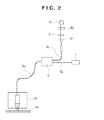
- Fig. 2 is a view showing the whole configuration of an interferometer of the first embodiment
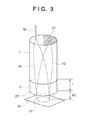
- Fig. 3 is an enlarged view of the main components of a photodetector of the second embodiment
- Fig. 4 is an enlarged view of the major components of a photodetector of the third embodiment
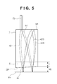
- Fig. 5 is an enlarged view of the major parts of a photodetector of the fourth embodiment
- Fig. 6 is an enlarged view of the main components of a photodetector of the fifth embodiment
- Fig. 7 is a schematic view of a conventional interferometer
- Fig. 8 is a conceptual view of the signal outputs of the conventional interferometer.
- Fig. 9 is a view for explaining an interpolation error when a measurement error caused by ghost light occurs.
- FIGs. 1 and 2 are views showing the arrangements of an interferometer of the first embodiment.
- a laser beam emitted from a light source 1 and having a wavelength ⁇ (633 nm) is guided to a single-mode fiber 6a, and then guided to a photodetector 10 through a branching filter 9 and single-mode fiber 6b.
- the laser beam of linear polarization light emitted from the fiber 6b is collimated by a gradient index lens (Grin lens) 7, and guided to a rutile plate 8 as an element of a birefringent material.
- a PBS film 2P as a first polarization beam splitter is deposited on the end face of the rutile plate 8 having a thickness T.
- the rutile plate 8 is located between the end portion of the fiber 6b and the PBS film 2P.
- the PBS film 2P transmits the P wave (a first polarization component) as reference light, and the S wave (a second polarization component) as measurement light.
- the PBS film 2P can be a PBS film formed by a microstructure.
- the S wave as the measurement light is transmitted through the PBS film 2P, and reflected to the same optical path again by a reflecting surface 4b as a surface to be measured.
- the S wave then converges through the rutile plate 8 and Grin lens 7, and is guided to the fiber 6b again.
- the P wave as the reference light converges through the rutile plate 8 and Grin lens 7, and is guided to the fiber 6b again.
- the S wave as the measurement light and the P wave as the reference light are retransmitted through the fiber 6b, guided to the branching filter 9, and then guided to a fiber 6c this time.
- the light beam diverging from the end face of the fiber 6c is collimated into parallel light by a lens 31 and transmitted through a ⁇ /4 plate 3 and polarizing plate 3B.
- a light-receiving device 16 receives interfering light of the measurement light and reference light. When the reflecting surface 4b moves in the optical-axis direction, only the phase of the S wave as the measurement light changes.
- the light beam transmitted through the ⁇ /4 plate 3 is rotating linear polarization light.
- the light beam is further converted into a bright-and-dark signal of light through the polarizing plate 3B.
- the photodetector 10 is made compact.
- reference light and measurement light normally have different optical path lengths. Therefore, the light source 1 is limited to a longitudinal-single-mode light source having a high coherency.
- the interferometer of the first embodiment has the following feature because the rutile plate 8 is used. When the optical axis of an extraordinary ray of the rutile plate 8 is aligned with the polarization axis of the above-mentioned P wave, the rutile transmission optical path length of the P wave is longer by T x 0.3 than that of the S wave.
- the P wave and S wave are transmitted, and the optical path length of the S wave entering the reflecting surface 4b looks long by a distance WD between the end face of the PBS film 2P and the reflecting surface 4b.
- the wave-optics optical path lengths of the P wave and S wave equal when WD is T x 0.3. That is, although the optical system is a Fizeau interferometer, the function of the rutile plate 8 formed before the PBS film 2P makes it possible to equalize the optical path lengths of the measurement light and reference light. Accordingly, a signal can be output in a position spaced apart from the PBS film 2P even when using a low-coherency light source. This broadens the range of selection of the light source 1.
- the utility value increases because the interferometer can be used in micro-range peak detection and the like.
- a super luminescent diode (SLD) light source or white-light-interfering light as the light source 1
- the utility value increases because the interferometer can be used in micro-range peak detection and the like.
- ghost light components of the P wave and S wave not reflected by the reflecting surface 4b or PBS film 2P a defined number of times have optical path lengths different from those of the P wave and S wave reflected by the defined number of times. Since, therefore, the ghost light (stray light) does not generate any interference signal, it is possible to largely prevent the reduction in measurement accuracy caused by the ghost light.
- the birefringent-material element 8 is formed by a rutile plate.
- the same effect can be obtained even when the birefringent-material element is formed by a material having the birefringent effect like the rutile plate, for example, calcite or yttrium vanadate.
- FIG. 3 is a view showing the arrangement of an interferometer of the second embodiment.
- the second embodiment differs from the first embodiment in the arrangement of a photodetector 10. More specifically, a fiber 6b that emits a light beam toward the photodetector 10 is placed in a position offset from the center of a Grin lens 7. Also, a mirror surface 5P is formed in a position on the Grin lens, which is opposite to a portion where the fiber 6b emits the light beam.
- the mirror surface 5P forms a first mirror surface that reflects, toward a PBS film 2P, measurement light reflected by a reflecting surface 4b and transmitted through the PBS film 2P, and reference light reflected by the PBS film 2P.
- a light beam 40 emitted from the fiber 6b is split into measurement light 41 transmitted through the PBS film 2P, and reference light 42 reflected by the PBS film 2P.
- the measurement light 41 propagates from the PBS film 2P to the fiber 6b via the reflecting surface 4b, the PBS film 2P, the mirror surface 5P, the PBS film 2P, the reflecting surface 4b, the PBS film 2P, and a rutile plate 8.
- the reference light 42 propagates from the PBS film 2P to the fiber 6b via the mirror surface 5P, PBS film 2P, and rutile plate 8.
- the interferometer of the second embodiment forms a double-path Fizeau interferometer as described above, a sine signal having a period of ⁇ /4 is obtained for the movement of the reflecting surface 4b.
- ghost light is generated to some extent due to the performance of the extinction ratio of the PBS film 2P.
- a signal having a period of ⁇ /2 is output from the movement of the reflecting surface 4b.
- ghost light components when using a light source having a broad wavelength such as an SLD light source, ghost light components have optical path lengths different from those of both reference light and measurement light as main light components, and hence do not generate any interference signal. It is thus possible to prevent the interference of the ghost light components in the second embodiment as well. Since this improves the quality of an interference signal of a displacement signal, the interferometer is applicable to very-high-accuracy measurements.
- FIG. 4 is a view showing the arrangement of an interferometer of the third embodiment.
- the third embodiment differs from the first embodiment in the arrangement of a photodetector 10, and uses the same light source 1 and light-receiving device 16 as those of the first embodiment.
- a laser beam 40 emitted from a fiber 6b is collimated into a parallel light beam by a Grin lens 7, and enters a PBS film 2PA.
- the PBS film 2PA is formed by a microstructure using a semiconductor process or the like. The direction of this microstructure is set such that the PBS film 2PA reflects the P wave and transmits the S wave.
- the S wave as measurement light 41 is transmitted through the PBS film 2PA, reflected by a reflecting surface 4b, retransmitted through the PBS film 2PA, and collimated into a converged light beam again by the Grin lens 7, and this converged light beam enters a PBS film 2PB.
- the P wave as reference light 42 is reflected by the PBS film 2PA, and collimated into a converged light beam by the Grin lens 7 like the measurement light 41, and this converted light beam enters the PBS film 2PB.
- the PBS film 2PB has a microstructure similar to that of the PBS film 2PA, but the direction of this microstructure is set to be perpendicular to the PBS film 2PA.
- the PBS film 2PB reflects the S wave as the measurement light 41, and transmits the P wave as the reference light 42.
- the PBS film 2PB forms a second polarization beam splitter that reflects, toward the PBS film 2PA, the measurement light 41 reflected by the reflecting surface 4b and transmitted through the PBS film 2PA, and transmits the reference light 42 reflected by the PBS film 2PA.
- the reference light 42 transmitted through the PBS film 2PB is reflected by a Fresnel mirror 5P set in a position spaced apart by a distance T from the PBS film 2PB, and re-enters the PBS film 2PB through the same optical path.
- the surface of the Fresnel mirror 5P forms a second mirror surface that reflects, toward the PBS film 2PB, the reference light 42 transmitted through the PBS film 2PB.
- the S wave as the measurement light 41 and the P wave as the reference light 42 re-enter the PBS film 2PA, the measurement light 41 is transmitted through the PBS film 2PA, reflected by the reflecting surface 4b, retransmitted through the PBS film 2PA, and combined with the reference light 42 reflected by the PBS film 2PA again, and the combined light converges to the fiber 6b.
- the wave-optics optical path lengths of the measurement light 41 and reference light 42 are equal, so an interferometer having equal optical paths in positions spatially apart from the PBS film 2PA can be formed as in the first and second embodiments. Accordingly, an interferometer using a light source such as an SLD can be formed by a Fizeau optical system in the third embodiment as well. This makes it possible to obtain the same effect as that of the second embodiment against ghost light.
- the surface of the Fresnel mirror 5P is used as the second mirror surface for reflecting, toward the PBS film 2PB, the reference light transmitted through the PBS film 2PB.
- the surface of a spherical mirror can also be used as the second mirror surface.
- the PBS film 2PB and the Fresnel mirror 5P as the second mirror are separately installed.
- FIG. 5 is a view showing the arrangement of an interferometer of the fourth embodiment.
- the interferometer of the fourth embodiment has the same arrangement as that of the interferometer of the second embodiment except that a PBS film 2P is located to incline to a plane on which a reflecting surface 4b is to be positioned. Inclining the PBS film 2P improves the effect of removing ghost light components. In double optical paths, a light beam reflected by the reflecting surface 4b and PBS film 2P for the first time is separated into light beams 42A and 42B, but light beams reflected by a mirror surface 5P and reflected toward a fiber 6b by the reflecting surface 4b and PBS film 2P again are accurately superposed and combined.
- a light beam having entered the reflecting surface 4b a defined number of times propagates toward the fiber 6b and generates an interference signal, but a ghost light component not having entered the reflecting surface 4b the defined number of times finally generates a light beam 44, and cannot be guided to the fiber 6b.
- the interferometer of the fourth embodiment more effectively removes fine ghost light components. Therefore, the final signal distortion is small, and the signal-to-noise ratio (S/N ratio) can be increased. This makes the interferometer more effective in ultra-high-accuracy measurements.
- FIG. 6 is a view showing the arrangement of an interferometer of the fifth embodiment.
- the interferometer of the fifth embodiment has the same arrangement as that of the interferometer of the third embodiment except that a PBS film 2PA is located to incline to a plane on which a reflecting surface 4b is to be positioned. Inclining the PBS film 2PA achieves the same effect as that of the fourth embodiment, and is effective in ultra-high-accuracy measurements.
- the first to fifth embodiments are applicable to an interferometer or displacement sensor for measuring a micro displacement by converting the phase modulation of light such as a laser beam into intensity-modulated light.
- An interferometer comprises: a light source (1); a first polarization beam splitter (2P) configured to reflect, as reference light, a first polarization component of light emitted from the light source, and to transmit, as measurement light, a second polarization component of the light emitted from the light source; a birefringent-material element (8) located between the light source and the first polarization beam splitter; and a light-receiving device (16) configured to receive an interfering light generated by interference of the measurement light transmitted through the first polarization beam splitter, reflected by a reflecting surface (4b) to be measured, and transmitted through the first polarization beam splitter, with the reference light reflected by the first polarization beam splitter.
- the interferometer is configured such that the reference light, a first polarization component of light emitted from the light source, and to transmit, as measurement light, a second polarization component of the light emitted from the light source.
- a birefringent-material element (8) located
Landscapes
- Physics & Mathematics (AREA)
- General Physics & Mathematics (AREA)
- Instruments For Measurement Of Length By Optical Means (AREA)
- Length Measuring Devices By Optical Means (AREA)
Abstract
Description
- The present invention relates to an interferometer that modulates a measurement light with a reference light to obtain a modulated light having a phase associated with movement of an object, and converts the modulated light into an electrical signal by a light-receiving device to obtain information of displacement of the object.
- Conventionally, a laser interferometer having high accuracy and high resolution is used as an apparatus for measuring the displacement of an object such as a stage.
Fig. 7 is a view showing the arrangement of a conventional interferometer. This interferometer is disclosed in Japanese Patent Laid-Open No.05-071913 laser beam 11 emitted from a light source 1 and having a wavelength λ (633 nm) enters a polarization beam splitter (PBS) 2, and is split intoreference light 12a andmeasurement light 12b by aPBS plane 2P. Thereference light 12a is reflected by areference mirror 4a and re-enters thePBS 2 through the same optical path. Since thereference light 12a is transmitted through a λ/4 plate 3a twice, the P wave is converted into the S wave. Therefore, thereference light 12a is transmitted through thePBS plane 2P this time, and enters areflective element 5 as alight beam 13a. On the other hand, themeasurement light 12b is reflected by a reflectingsurface 4b, and re-enters thePBS 2 through the same optical path. Since themeasurement light 12b is transmitted through a λ/4plate 3b twice, the S wave is converted into the P wave. Accordingly, themeasurement light 12b is reflected by thePBS plane 2P this time, and enters thereflective element 5 as alight beam 13b like thereference light 13a. After that, the reference light is retransmitted through thePBS 2 to form a light beam 14a, and themeasurement light 12b is reflected by thePBS 2 again to form a light beam 14b. The light beams 14a and 14b are transmitted through the λ/4 plate twice, and re-enter thePBS 2. The light beams 14a and 14b are combined into alight beam 15, and an interference signal having a λ/4 period is obtained by the movement of the reflectingsurface 4b. - In the conventional interferometer shown in
Fig. 7 , a large number of reflecting surfaces exist in the optical paths. For example, a component reflected by a reflectingsurface 21b of the λ/4plate 3b propagates through the same optical path as that of ordinary measurement light. This component is finally superposed on thelight beam 15, and modulated by the movement of the reflectingsurface 4b. However, the component reflected by the reflectingsurface 21b of the λ/4plate 3b arrives at the reflectingsurface 4b after being reflected only once. Therefore, the modulation amount is half that of the ordinary reflection component, and an interference signal having a period of λ/2 is obtained. Assuming that the reflectance of an antireflection coat (AR coat) of the reflectingsurface 21b is 0.2%, the interference intensity of an interference signal generated from ghost light (stray light) reflected by the reflectingsurface 21b is about 9% that of a main signal from the viewpoint of wave optics. Even when an AR coat having a very low reflectance of 0.01% is formed, an interference intensity of 2.5% is generated. A waveform as shown inFig. 8 is obtained because sine-wave signals caused by all ghost light components are superposed on an electrical signal output from a light-receivingdevice 16. It is normally possible to obtain a sub-nanometer resolution by electrically dividing a sine-wave periodical signal modulated in accordance with the obtained displacement. However, deterioration of the linearity as shown inFig. 9 occurs in the signal on which the components caused by the ghost light are superposed, and the error amount reaches a few nm to a few ten nm. This poses a serious problem in ultra-high-accuracy applications. - The present invention provides an interferometer advantageous in terms of measurement precision.
- According to one aspect of the present invention, there is provided an interferometer as specified in claims 1 to 8.
- Further features of the present invention will become apparent from the following description of exemplary embodiments with reference to the attached drawings.
-
Fig. 1 is an enlarged view of the main parts of a photodetector of the first embodiment; -
Fig. 2 is a view showing the whole configuration of an interferometer of the first embodiment; -
Fig. 3 is an enlarged view of the main components of a photodetector of the second embodiment; -
Fig. 4 is an enlarged view of the major components of a photodetector of the third embodiment; -
Fig. 5 is an enlarged view of the major parts of a photodetector of the fourth embodiment; -
Fig. 6 is an enlarged view of the main components of a photodetector of the fifth embodiment; -
Fig. 7 is a schematic view of a conventional interferometer; -
Fig. 8 is a conceptual view of the signal outputs of the conventional interferometer; and -
Fig. 9 is a view for explaining an interpolation error when a measurement error caused by ghost light occurs. - Embodiments of the present invention will be explained below with reference to the accompanying drawings.
- [First Embodiment]
Figs. 1 and2 are views showing the arrangements of an interferometer of the first embodiment. A laser beam emitted from a light source 1 and having a wavelength λ (633 nm) is guided to a single-mode fiber 6a, and then guided to aphotodetector 10 through a branching filter 9 and single-mode fiber 6b. The laser beam of linear polarization light emitted from thefiber 6b is collimated by a gradient index lens (Grin lens) 7, and guided to a rutile plate 8 as an element of a birefringent material. APBS film 2P as a first polarization beam splitter is deposited on the end face of the rutile plate 8 having a thickness T. That is, the rutile plate 8 is located between the end portion of thefiber 6b and thePBS film 2P. Of the light emitted from the light source 1, thePBS film 2P transmits the P wave (a first polarization component) as reference light, and the S wave (a second polarization component) as measurement light. The PBSfilm 2P can be a PBS film formed by a microstructure. The S wave as the measurement light is transmitted through thePBS film 2P, and reflected to the same optical path again by a reflectingsurface 4b as a surface to be measured. The S wave then converges through the rutile plate 8 and Grinlens 7, and is guided to thefiber 6b again. On the other hand, the P wave as the reference light converges through the rutile plate 8 and Grinlens 7, and is guided to thefiber 6b again. The S wave as the measurement light and the P wave as the reference light are retransmitted through thefiber 6b, guided to the branching filter 9, and then guided to afiber 6c this time. The light beam diverging from the end face of thefiber 6c is collimated into parallel light by alens 31 and transmitted through a λ/4 plate 3 and polarizingplate 3B. A light-receivingdevice 16 receives interfering light of the measurement light and reference light. When the reflectingsurface 4b moves in the optical-axis direction, only the phase of the S wave as the measurement light changes. Therefore, the light beam transmitted through the λ/4 plate 3 is rotating linear polarization light. The light beam is further converted into a bright-and-dark signal of light through the polarizingplate 3B. This signal is a sine signal having a period that changes at λ/2 = 316.5 nm. - Since the optical system shown in
Fig. 2 forms a Fizeau interferometer as explained above, thephotodetector 10 is made compact. In a Fizeau optical system, reference light and measurement light normally have different optical path lengths. Therefore, the light source 1 is limited to a longitudinal-single-mode light source having a high coherency. However, the interferometer of the first embodiment has the following feature because the rutile plate 8 is used. When the optical axis of an extraordinary ray of the rutile plate 8 is aligned with the polarization axis of the above-mentioned P wave, the rutile transmission optical path length of the P wave is longer by T x 0.3 than that of the S wave. That is, geometrically, the P wave and S wave are transmitted, and the optical path length of the S wave entering the reflectingsurface 4b looks long by a distance WD between the end face of thePBS film 2P and the reflectingsurface 4b. In practice, however, the wave-optics optical path lengths of the P wave and S wave equal when WD is T x 0.3. That is, although the optical system is a Fizeau interferometer, the function of the rutile plate 8 formed before thePBS film 2P makes it possible to equalize the optical path lengths of the measurement light and reference light. Accordingly, a signal can be output in a position spaced apart from thePBS film 2P even when using a low-coherency light source. This broadens the range of selection of the light source 1. For example, when using a super luminescent diode (SLD) light source or white-light-interfering light as the light source 1, the utility value increases because the interferometer can be used in micro-range peak detection and the like. Also, when using a low-coherency light source, ghost light components of the P wave and S wave not reflected by the reflectingsurface 4b orPBS film 2P a defined number of times have optical path lengths different from those of the P wave and S wave reflected by the defined number of times. Since, therefore, the ghost light (stray light) does not generate any interference signal, it is possible to largely prevent the reduction in measurement accuracy caused by the ghost light. In this embodiment, the birefringent-material element 8 is formed by a rutile plate. However, the same effect can be obtained even when the birefringent-material element is formed by a material having the birefringent effect like the rutile plate, for example, calcite or yttrium vanadate. - [Second Embodiment]
Fig. 3 is a view showing the arrangement of an interferometer of the second embodiment. The second embodiment differs from the first embodiment in the arrangement of aphotodetector 10. More specifically, afiber 6b that emits a light beam toward thephotodetector 10 is placed in a position offset from the center of aGrin lens 7. Also, amirror surface 5P is formed in a position on the Grin lens, which is opposite to a portion where thefiber 6b emits the light beam. Themirror surface 5P forms a first mirror surface that reflects, toward aPBS film 2P, measurement light reflected by a reflectingsurface 4b and transmitted through thePBS film 2P, and reference light reflected by thePBS film 2P. - A
light beam 40 emitted from thefiber 6b is split intomeasurement light 41 transmitted through thePBS film 2P, andreference light 42 reflected by thePBS film 2P. Themeasurement light 41 propagates from thePBS film 2P to thefiber 6b via the reflectingsurface 4b, thePBS film 2P, themirror surface 5P, thePBS film 2P, the reflectingsurface 4b, thePBS film 2P, and a rutile plate 8. On the other hand, thereference light 42 propagates from thePBS film 2P to thefiber 6b via themirror surface 5P,PBS film 2P, and rutile plate 8. - Since the interferometer of the second embodiment forms a double-path Fizeau interferometer as described above, a sine signal having a period of λ/4 is obtained for the movement of the reflecting
surface 4b. In this arrangement, ghost light is generated to some extent due to the performance of the extinction ratio of thePBS film 2P. For example, if the S wave to be transmitted is reflected to pass through the internal optical system again and then transmitted through thePBS film 2P, a signal having a period of λ/2 is output from the movement of the reflectingsurface 4b. However, when using a light source having a broad wavelength such as an SLD light source, ghost light components have optical path lengths different from those of both reference light and measurement light as main light components, and hence do not generate any interference signal.
It is thus possible to prevent the interference of the ghost light components in the second embodiment as well. Since this improves the quality of an interference signal of a displacement signal, the interferometer is applicable to very-high-accuracy measurements. - [Third Embodiment]
Fig. 4 is a view showing the arrangement of an interferometer of the third embodiment. The third embodiment differs from the first embodiment in the arrangement of aphotodetector 10, and uses the same light source 1 and light-receivingdevice 16 as those of the first embodiment. Alaser beam 40 emitted from afiber 6b is collimated into a parallel light beam by aGrin lens 7, and enters a PBS film 2PA. The PBS film 2PA is formed by a microstructure using a semiconductor process or the like. The direction of this microstructure is set such that the PBS film 2PA reflects the P wave and transmits the S wave. Accordingly, the S wave asmeasurement light 41 is transmitted through the PBS film 2PA, reflected by a reflectingsurface 4b, retransmitted through the PBS film 2PA, and collimated into a converged light beam again by theGrin lens 7, and this converged light beam enters a PBS film 2PB. On the other hand, the P wave asreference light 42 is reflected by the PBS film 2PA, and collimated into a converged light beam by theGrin lens 7 like themeasurement light 41, and this converted light beam enters the PBS film 2PB. The PBS film 2PB has a microstructure similar to that of the PBS film 2PA, but the direction of this microstructure is set to be perpendicular to the PBS film 2PA. Therefore, the PBS film 2PB reflects the S wave as themeasurement light 41, and transmits the P wave as thereference light 42. The PBS film 2PB forms a second polarization beam splitter that reflects, toward the PBS film 2PA, themeasurement light 41 reflected by the reflectingsurface 4b and transmitted through the PBS film 2PA, and transmits thereference light 42 reflected by the PBS film 2PA. Thereference light 42 transmitted through the PBS film 2PB is reflected by aFresnel mirror 5P set in a position spaced apart by a distance T from the PBS film 2PB, and re-enters the PBS film 2PB through the same optical path. The surface of theFresnel mirror 5P forms a second mirror surface that reflects, toward the PBS film 2PB, thereference light 42 transmitted through the PBS film 2PB. The S wave as themeasurement light 41 and the P wave as thereference light 42 re-enter the PBS film 2PA, themeasurement light 41 is transmitted through the PBS film 2PA, reflected by the reflectingsurface 4b, retransmitted through the PBS film 2PA, and combined with thereference light 42 reflected by the PBS film 2PA again, and the combined light converges to thefiber 6b. When T = WD in the above-mentioned arrangement, the wave-optics optical path lengths of themeasurement light 41 andreference light 42 are equal, so an interferometer having equal optical paths in positions spatially apart from the PBS film 2PA can be formed as in the first and second embodiments. Accordingly, an interferometer using a light source such as an SLD can be formed by a Fizeau optical system in the third embodiment as well. This makes it possible to obtain the same effect as that of the second embodiment against ghost light. In this embodiment, the surface of theFresnel mirror 5P is used as the second mirror surface for reflecting, toward the PBS film 2PB, the reference light transmitted through the PBS film 2PB. However, the surface of a spherical mirror can also be used as the second mirror surface. Furthermore, in this embodiment, the PBS film 2PB and theFresnel mirror 5P as the second mirror are separately installed. However, it is also possible to use the PBS film 2PB andFresnel mirror 5P formed on a single substrate. - [Fourth Embodiment]
Fig. 5 is a view showing the arrangement of an interferometer of the fourth embodiment. The interferometer of the fourth embodiment has the same arrangement as that of the interferometer of the second embodiment except that aPBS film 2P is located to incline to a plane on which a reflectingsurface 4b is to be positioned. Inclining thePBS film 2P improves the effect of removing ghost light components. In double optical paths, a light beam reflected by the reflectingsurface 4b andPBS film 2P for the first time is separated intolight beams mirror surface 5P and reflected toward afiber 6b by the reflectingsurface 4b andPBS film 2P again are accurately superposed and combined. That is, a light beam having entered the reflectingsurface 4b a defined number of times propagates toward thefiber 6b and generates an interference signal, but a ghost light component not having entered the reflectingsurface 4b the defined number of times finally generates alight beam 44, and cannot be guided to thefiber 6b. The interferometer of the fourth embodiment more effectively removes fine ghost light components. Therefore, the final signal distortion is small, and the signal-to-noise ratio (S/N ratio) can be increased. This makes the interferometer more effective in ultra-high-accuracy measurements. - [Fifth Embodiment]
Fig. 6 is a view showing the arrangement of an interferometer of the fifth embodiment. The interferometer of the fifth embodiment has the same arrangement as that of the interferometer of the third embodiment except that a PBS film 2PA is located to incline to a plane on which a reflectingsurface 4b is to be positioned. Inclining the PBS film 2PA achieves the same effect as that of the fourth embodiment, and is effective in ultra-high-accuracy measurements. - The first to fifth embodiments are applicable to an interferometer or displacement sensor for measuring a micro displacement by converting the phase modulation of light such as a laser beam into intensity-modulated light.
- While the present invention has been described with reference to exemplary embodiments, it is to be understood that the invention is not limited to the disclosed exemplary embodiments. The scope of the following claims is to be accorded the broadest interpretation so as to encompass all such modifications and equivalent structures and functions.
An interferometer comprises: a light source (1); a first polarization beam splitter (2P) configured to reflect, as reference light, a first polarization component of light emitted from the light source, and to transmit, as measurement light, a second polarization component of the light emitted from the light source; a birefringent-material element (8) located between the light source and the first polarization beam splitter; and a light-receiving device (16) configured to receive an interfering light generated by interference of the measurement light transmitted through the first polarization beam splitter, reflected by a reflecting surface (4b) to be measured, and transmitted through the first polarization beam splitter, with the reference light reflected by the first polarization beam splitter. The interferometer is configured such that the reference light and the measurement light pass through the birefringent-material element between the first polarization beam splitter and the light-receiving device.
Claims (8)
- An interferometer characterized by comprising:a light source (1);a first polarization beam splitter (2P) configured to reflect, as reference light, a first polarization component of light emitted from said light source, and to transmit, as measurement light, a second polarization component of the light emitted from said light source;a birefringent-material element (8) located between said light source and said first polarization beam splitter; anda light-receiving device (16) configured to receive an interfering light generated by interference of the measurement light transmitted through said first polarization beam splitter, reflected by a reflecting surface (4b) to be measured, and transmitted through said first polarization beam splitter, with the reference light reflected by said first polarization beam splitter,wherein the interferometer is configured such that the reference light and the measurement light pass through said birefringent-material element between said first polarization beam splitter and said light-receiving device.
- The interferometer according to claim 1, characterized by further comprising a first mirror surface configured to reflect, toward said first polarization beam splitter, the measurement light reflected by said reflecting surface and transmitted through said first polarization beam splitter and the reference light reflected by said first polarization beam splitter,
wherein the interferometer is configured such that the measurement light propagates from said first polarization beam splitter to said light-receiving device via said reflecting surface, said first polarization beam splitter, said first mirror surface, said first polarization beam splitter, said reflecting surface, said first polarization beam splitter, and said birefringent-material element, and
the reference light propagates from said first polarization beam splitter to said light-receiving device via said first mirror surface, said first polarization beam splitter, and said birefringent-material device. - An interferometer characterized by comprising:a light source (1);a first polarization beam splitter (2PA) configured to reflect, as reference light, a first polarization component of light emitted from said light source, and to transmit, as measurement light, a second polarization component of the light emitted from said light source;a second polarization beam splitter (2PB) configured to reflect, toward said first polarization beam splitter, the measurement light transmitted through said first polarization beam splitter, reflected by a reflecting surface (4b) to be measured, and transmitted through said first polarization beam splitter, and transmits the reference light reflected by said first polarization beam splitter;a second mirror surface (5P) configured to reflect, toward said second polarization beam splitter, the reference light transmitted through said second polarization beam splitter; anda light-receiving device (16) configured to receive an interfering light generated by interference of the measurement light with the reference light,wherein the interferometer is configured such thatthe measurement light propagates from said first polarization beam splitter to said light-receiving device via said reflecting surface, said first polarization beam splitter, said second polarization beam splitter, said first polarization beam splitter, said reflecting surface, and said first polarization beam splitter, andthe reference light propagates from said first polarization beam splitter to said light-receiving device via said second polarization beam splitter, said second mirror surface, said second polarization beam splitter, and said first polarization beam splitter.
- The interferometer according to claim 3, characterized in that said second mirror surface is a surface of a spherical mirror.
- The interferometer according to claim 3, characterized in that said second mirror surface is a surface of a Fresnel mirror.
- The interferometer according to claim 5, characterized in that said Fresnel mirror and said second polarization beam splitter are formed on a single substrate.
- The interferometer according to any one of claims 1 to 6, characterized in that said first polarization beam splitter is inclined to a plane on which said reflecting surface is to be positioned.
- The interferometer according to any one of claims 1 to 7, characterized in that said light source comprises a super luminescent diode.
Applications Claiming Priority (1)
| Application Number | Priority Date | Filing Date | Title |
|---|---|---|---|
| JP2009283432A JP5629455B2 (en) | 2009-12-14 | 2009-12-14 | Interferometer |
Publications (2)
| Publication Number | Publication Date |
|---|---|
| EP2336714A1 true EP2336714A1 (en) | 2011-06-22 |
| EP2336714B1 EP2336714B1 (en) | 2014-05-21 |
Family
ID=43646496
Family Applications (1)
| Application Number | Title | Priority Date | Filing Date |
|---|---|---|---|
| EP10191358.0A Not-in-force EP2336714B1 (en) | 2009-12-14 | 2010-11-16 | Interferometer |
Country Status (3)
| Country | Link |
|---|---|
| US (1) | US9372066B2 (en) |
| EP (1) | EP2336714B1 (en) |
| JP (1) | JP5629455B2 (en) |
Cited By (1)
| Publication number | Priority date | Publication date | Assignee | Title |
|---|---|---|---|---|
| CN110006349A (en) * | 2019-04-29 | 2019-07-12 | 西安交通大学 | A kind of high tolerance is total to optical path grating interferometer |
Families Citing this family (2)
| Publication number | Priority date | Publication date | Assignee | Title |
|---|---|---|---|---|
| JP5993207B2 (en) * | 2012-05-22 | 2016-09-14 | 東京エレクトロン株式会社 | Optical interference system and substrate processing apparatus |
| CN105258635A (en) * | 2015-11-09 | 2016-01-20 | 中国科学院长春光学精密机械与物理研究所 | Standard reference lens for broadband Fizeau laser interferometer |
Citations (4)
| Publication number | Priority date | Publication date | Assignee | Title |
|---|---|---|---|---|
| US5153669A (en) * | 1991-03-27 | 1992-10-06 | Hughes Danbury Optical Systems, Inc. | Three wavelength optical measurement apparatus and method |
| JPH0571913A (en) | 1991-09-11 | 1993-03-23 | Fuji Xerox Co Ltd | Interferometer |
| US20030197869A1 (en) * | 2002-04-18 | 2003-10-23 | Johnstone Eric S. | Interferometer using beam re-tracing to eliminate beam walk-off |
| US20040246490A1 (en) * | 2003-06-04 | 2004-12-09 | Feiling Wang | Measurements of substances using two different propagation modes of light through a common optical path |
Family Cites Families (19)
| Publication number | Priority date | Publication date | Assignee | Title |
|---|---|---|---|---|
| US3520615A (en) * | 1965-10-25 | 1970-07-14 | Vickers Ltd | Optical phase measuring apparatus |
| JPS6055206A (en) * | 1983-09-05 | 1985-03-30 | Japan Aviation Electronics Ind Ltd | Light interference meter |
| JPH0454406A (en) * | 1990-06-25 | 1992-02-21 | Toyota Autom Loom Works Ltd | Optical displacement gauge |
| US6229619B1 (en) * | 1996-02-12 | 2001-05-08 | Massachusetts Institute Of Technology | Compensation for measurement uncertainty due to atmospheric effects |
| JPH1166600A (en) * | 1997-08-08 | 1999-03-09 | Tdk Corp | Light receiving and emitting device and optical pickup apparatus |
| US6455861B1 (en) * | 1998-11-24 | 2002-09-24 | Cambridge Research & Instrumentation, Inc. | Fluorescence polarization assay system and method |
| JP2000234914A (en) * | 1999-02-15 | 2000-08-29 | Tokimec Inc | Strain detector |
| JP2001256654A (en) * | 2000-03-13 | 2001-09-21 | Optware:Kk | Optical information recording device, optical information reproducing device, optical information recording / reproducing device, and optical information recording medium |
| DE60001139T2 (en) * | 2000-08-16 | 2003-09-11 | Agilent Technologies, Inc. (N.D.Ges.D.Staates Delaware) | Wavelength meter with coarse and fine measuring system |
| US6816261B2 (en) * | 2001-05-15 | 2004-11-09 | Optellios, Inc. | Polarization analysis unit, calibration method and optimization therefor |
| US6778280B2 (en) * | 2001-07-06 | 2004-08-17 | Zygo Corporation | Interferometry system and method employing an angular difference in propagation between orthogonally polarized input beam components |
| WO2005003862A1 (en) * | 2003-07-05 | 2005-01-13 | Carl Zeiss Smt Ag | Device for the polarization-specific examination of an optical system |
| JP4514209B2 (en) * | 2004-10-15 | 2010-07-28 | キヤノン株式会社 | Position detection apparatus and method |
| JP4939765B2 (en) * | 2005-03-28 | 2012-05-30 | 株式会社日立製作所 | Displacement measuring method and apparatus |
| JP4914040B2 (en) * | 2005-07-28 | 2012-04-11 | キヤノン株式会社 | Interference measurement device |
| DE602006017558D1 (en) * | 2005-08-09 | 2010-11-25 | Gen Hospital Corp | DEVICE AND METHOD FOR CARRYING OUT POLARIZATION-BASED QUADRATURE DEMODULATION IN OPTICAL COHERENCE TOMOGRAPHY |
| JP4810693B2 (en) * | 2007-02-09 | 2011-11-09 | 富士フイルム株式会社 | Lightwave interference measurement device |
| JP5305732B2 (en) * | 2008-05-13 | 2013-10-02 | キヤノン株式会社 | Interferometer |
| US20110075153A1 (en) * | 2009-09-25 | 2011-03-31 | Hogan Josh N | Compact isolated analysis system |
-
2009
- 2009-12-14 JP JP2009283432A patent/JP5629455B2/en not_active Expired - Fee Related
-
2010
- 2010-11-16 EP EP10191358.0A patent/EP2336714B1/en not_active Not-in-force
- 2010-12-13 US US12/966,210 patent/US9372066B2/en not_active Expired - Fee Related
Patent Citations (4)
| Publication number | Priority date | Publication date | Assignee | Title |
|---|---|---|---|---|
| US5153669A (en) * | 1991-03-27 | 1992-10-06 | Hughes Danbury Optical Systems, Inc. | Three wavelength optical measurement apparatus and method |
| JPH0571913A (en) | 1991-09-11 | 1993-03-23 | Fuji Xerox Co Ltd | Interferometer |
| US20030197869A1 (en) * | 2002-04-18 | 2003-10-23 | Johnstone Eric S. | Interferometer using beam re-tracing to eliminate beam walk-off |
| US20040246490A1 (en) * | 2003-06-04 | 2004-12-09 | Feiling Wang | Measurements of substances using two different propagation modes of light through a common optical path |
Cited By (1)
| Publication number | Priority date | Publication date | Assignee | Title |
|---|---|---|---|---|
| CN110006349A (en) * | 2019-04-29 | 2019-07-12 | 西安交通大学 | A kind of high tolerance is total to optical path grating interferometer |
Also Published As
| Publication number | Publication date |
|---|---|
| JP5629455B2 (en) | 2014-11-19 |
| US9372066B2 (en) | 2016-06-21 |
| US20110141479A1 (en) | 2011-06-16 |
| EP2336714B1 (en) | 2014-05-21 |
| JP2011123037A (en) | 2011-06-23 |
Similar Documents
| Publication | Publication Date | Title |
|---|---|---|
| JP5087186B1 (en) | Iso-optical path interferometer | |
| US6643025B2 (en) | Microinterferometer for distance measurements | |
| US7864336B2 (en) | Compact Littrow encoder | |
| CN112484648B (en) | Displacement measurement system and method for heterodyne optical fiber interferometer | |
| Thurner et al. | Fabry-Pérot interferometry for long range displacement sensing | |
| US8848184B2 (en) | Optical position-measuring device | |
| JP5305732B2 (en) | Interferometer | |
| WO2002079720A1 (en) | Microinterferometer for distance measurements | |
| CN100425944C (en) | Position detection apparatus and method | |
| CN112484647B (en) | Interferometer displacement measurement system and method | |
| US9068811B2 (en) | Device for determining distance interferometrically | |
| US9372066B2 (en) | Interferometer | |
| JP2000186912A5 (en) | ||
| WO2011004692A1 (en) | Displacement measurement device using optical interferometer | |
| JP2018197659A (en) | Displacement detector | |
| JP5984555B2 (en) | Displacement detector | |
| JP2005106706A (en) | Refractive index and thickness measuring apparatus and measuring method | |
| JP3964260B2 (en) | Shape measuring device | |
| JP5969274B2 (en) | Position detection device | |
| JP2966950B2 (en) | Sample displacement measuring device | |
| JP2000088513A (en) | Aspheric wave generation lens system assembly adjustment device |
Legal Events
| Date | Code | Title | Description |
|---|---|---|---|
| PUAI | Public reference made under article 153(3) epc to a published international application that has entered the european phase |
Free format text: ORIGINAL CODE: 0009012 |
|
| AK | Designated contracting states |
Kind code of ref document: A1 Designated state(s): AL AT BE BG CH CY CZ DE DK EE ES FI FR GB GR HR HU IE IS IT LI LT LU LV MC MK MT NL NO PL PT RO RS SE SI SK SM TR |
|
| AX | Request for extension of the european patent |
Extension state: BA ME |
|
| 17P | Request for examination filed |
Effective date: 20111222 |
|
| GRAP | Despatch of communication of intention to grant a patent |
Free format text: ORIGINAL CODE: EPIDOSNIGR1 |
|
| INTG | Intention to grant announced |
Effective date: 20131217 |
|
| GRAS | Grant fee paid |
Free format text: ORIGINAL CODE: EPIDOSNIGR3 |
|
| GRAA | (expected) grant |
Free format text: ORIGINAL CODE: 0009210 |
|
| AK | Designated contracting states |
Kind code of ref document: B1 Designated state(s): AL AT BE BG CH CY CZ DE DK EE ES FI FR GB GR HR HU IE IS IT LI LT LU LV MC MK MT NL NO PL PT RO RS SE SI SK SM TR |
|
| REG | Reference to a national code |
Ref country code: GB Ref legal event code: FG4D |
|
| REG | Reference to a national code |
Ref country code: CH Ref legal event code: EP |
|
| REG | Reference to a national code |
Ref country code: AT Ref legal event code: REF Ref document number: 669804 Country of ref document: AT Kind code of ref document: T Effective date: 20140615 |
|
| REG | Reference to a national code |
Ref country code: IE Ref legal event code: FG4D |
|
| REG | Reference to a national code |
Ref country code: DE Ref legal event code: R096 Ref document number: 602010016212 Country of ref document: DE Effective date: 20140703 |
|
| REG | Reference to a national code |
Ref country code: NL Ref legal event code: VDEP Effective date: 20140521 Ref country code: AT Ref legal event code: MK05 Ref document number: 669804 Country of ref document: AT Kind code of ref document: T Effective date: 20140521 |
|
| REG | Reference to a national code |
Ref country code: LT Ref legal event code: MG4D |
|
| PG25 | Lapsed in a contracting state [announced via postgrant information from national office to epo] |
Ref country code: FI Free format text: LAPSE BECAUSE OF FAILURE TO SUBMIT A TRANSLATION OF THE DESCRIPTION OR TO PAY THE FEE WITHIN THE PRESCRIBED TIME-LIMIT Effective date: 20140521 Ref country code: LT Free format text: LAPSE BECAUSE OF FAILURE TO SUBMIT A TRANSLATION OF THE DESCRIPTION OR TO PAY THE FEE WITHIN THE PRESCRIBED TIME-LIMIT Effective date: 20140521 Ref country code: IS Free format text: LAPSE BECAUSE OF FAILURE TO SUBMIT A TRANSLATION OF THE DESCRIPTION OR TO PAY THE FEE WITHIN THE PRESCRIBED TIME-LIMIT Effective date: 20140921 Ref country code: NO Free format text: LAPSE BECAUSE OF FAILURE TO SUBMIT A TRANSLATION OF THE DESCRIPTION OR TO PAY THE FEE WITHIN THE PRESCRIBED TIME-LIMIT Effective date: 20140821 Ref country code: GR Free format text: LAPSE BECAUSE OF FAILURE TO SUBMIT A TRANSLATION OF THE DESCRIPTION OR TO PAY THE FEE WITHIN THE PRESCRIBED TIME-LIMIT Effective date: 20140822 |
|
| PG25 | Lapsed in a contracting state [announced via postgrant information from national office to epo] |
Ref country code: LV Free format text: LAPSE BECAUSE OF FAILURE TO SUBMIT A TRANSLATION OF THE DESCRIPTION OR TO PAY THE FEE WITHIN THE PRESCRIBED TIME-LIMIT Effective date: 20140521 Ref country code: ES Free format text: LAPSE BECAUSE OF FAILURE TO SUBMIT A TRANSLATION OF THE DESCRIPTION OR TO PAY THE FEE WITHIN THE PRESCRIBED TIME-LIMIT Effective date: 20140521 Ref country code: AT Free format text: LAPSE BECAUSE OF FAILURE TO SUBMIT A TRANSLATION OF THE DESCRIPTION OR TO PAY THE FEE WITHIN THE PRESCRIBED TIME-LIMIT Effective date: 20140521 Ref country code: PL Free format text: LAPSE BECAUSE OF FAILURE TO SUBMIT A TRANSLATION OF THE DESCRIPTION OR TO PAY THE FEE WITHIN THE PRESCRIBED TIME-LIMIT Effective date: 20140521 Ref country code: RS Free format text: LAPSE BECAUSE OF FAILURE TO SUBMIT A TRANSLATION OF THE DESCRIPTION OR TO PAY THE FEE WITHIN THE PRESCRIBED TIME-LIMIT Effective date: 20140521 Ref country code: SE Free format text: LAPSE BECAUSE OF FAILURE TO SUBMIT A TRANSLATION OF THE DESCRIPTION OR TO PAY THE FEE WITHIN THE PRESCRIBED TIME-LIMIT Effective date: 20140521 Ref country code: HR Free format text: LAPSE BECAUSE OF FAILURE TO SUBMIT A TRANSLATION OF THE DESCRIPTION OR TO PAY THE FEE WITHIN THE PRESCRIBED TIME-LIMIT Effective date: 20140521 |
|
| PG25 | Lapsed in a contracting state [announced via postgrant information from national office to epo] |
Ref country code: PT Free format text: LAPSE BECAUSE OF FAILURE TO SUBMIT A TRANSLATION OF THE DESCRIPTION OR TO PAY THE FEE WITHIN THE PRESCRIBED TIME-LIMIT Effective date: 20140922 |
|
| PG25 | Lapsed in a contracting state [announced via postgrant information from national office to epo] |
Ref country code: CZ Free format text: LAPSE BECAUSE OF FAILURE TO SUBMIT A TRANSLATION OF THE DESCRIPTION OR TO PAY THE FEE WITHIN THE PRESCRIBED TIME-LIMIT Effective date: 20140521 Ref country code: DK Free format text: LAPSE BECAUSE OF FAILURE TO SUBMIT A TRANSLATION OF THE DESCRIPTION OR TO PAY THE FEE WITHIN THE PRESCRIBED TIME-LIMIT Effective date: 20140521 Ref country code: SK Free format text: LAPSE BECAUSE OF FAILURE TO SUBMIT A TRANSLATION OF THE DESCRIPTION OR TO PAY THE FEE WITHIN THE PRESCRIBED TIME-LIMIT Effective date: 20140521 Ref country code: RO Free format text: LAPSE BECAUSE OF FAILURE TO SUBMIT A TRANSLATION OF THE DESCRIPTION OR TO PAY THE FEE WITHIN THE PRESCRIBED TIME-LIMIT Effective date: 20140521 Ref country code: EE Free format text: LAPSE BECAUSE OF FAILURE TO SUBMIT A TRANSLATION OF THE DESCRIPTION OR TO PAY THE FEE WITHIN THE PRESCRIBED TIME-LIMIT Effective date: 20140521 Ref country code: BE Free format text: LAPSE BECAUSE OF FAILURE TO SUBMIT A TRANSLATION OF THE DESCRIPTION OR TO PAY THE FEE WITHIN THE PRESCRIBED TIME-LIMIT Effective date: 20140521 |
|
| REG | Reference to a national code |
Ref country code: DE Ref legal event code: R097 Ref document number: 602010016212 Country of ref document: DE |
|
| PG25 | Lapsed in a contracting state [announced via postgrant information from national office to epo] |
Ref country code: NL Free format text: LAPSE BECAUSE OF FAILURE TO SUBMIT A TRANSLATION OF THE DESCRIPTION OR TO PAY THE FEE WITHIN THE PRESCRIBED TIME-LIMIT Effective date: 20140521 |
|
| PLBE | No opposition filed within time limit |
Free format text: ORIGINAL CODE: 0009261 |
|
| STAA | Information on the status of an ep patent application or granted ep patent |
Free format text: STATUS: NO OPPOSITION FILED WITHIN TIME LIMIT |
|
| 26N | No opposition filed |
Effective date: 20150224 |
|
| PG25 | Lapsed in a contracting state [announced via postgrant information from national office to epo] |
Ref country code: IT Free format text: LAPSE BECAUSE OF FAILURE TO SUBMIT A TRANSLATION OF THE DESCRIPTION OR TO PAY THE FEE WITHIN THE PRESCRIBED TIME-LIMIT Effective date: 20140521 |
|
| REG | Reference to a national code |
Ref country code: DE Ref legal event code: R097 Ref document number: 602010016212 Country of ref document: DE Effective date: 20150224 |
|
| PG25 | Lapsed in a contracting state [announced via postgrant information from national office to epo] |
Ref country code: MC Free format text: LAPSE BECAUSE OF FAILURE TO SUBMIT A TRANSLATION OF THE DESCRIPTION OR TO PAY THE FEE WITHIN THE PRESCRIBED TIME-LIMIT Effective date: 20140521 Ref country code: LU Free format text: LAPSE BECAUSE OF FAILURE TO SUBMIT A TRANSLATION OF THE DESCRIPTION OR TO PAY THE FEE WITHIN THE PRESCRIBED TIME-LIMIT Effective date: 20141116 |
|
| REG | Reference to a national code |
Ref country code: CH Ref legal event code: PL |
|
| GBPC | Gb: european patent ceased through non-payment of renewal fee |
Effective date: 20141116 |
|
| PG25 | Lapsed in a contracting state [announced via postgrant information from national office to epo] |
Ref country code: LI Free format text: LAPSE BECAUSE OF NON-PAYMENT OF DUE FEES Effective date: 20141130 Ref country code: SI Free format text: LAPSE BECAUSE OF FAILURE TO SUBMIT A TRANSLATION OF THE DESCRIPTION OR TO PAY THE FEE WITHIN THE PRESCRIBED TIME-LIMIT Effective date: 20140521 Ref country code: CH Free format text: LAPSE BECAUSE OF NON-PAYMENT OF DUE FEES Effective date: 20141130 |
|
| REG | Reference to a national code |
Ref country code: IE Ref legal event code: MM4A |
|
| REG | Reference to a national code |
Ref country code: FR Ref legal event code: ST Effective date: 20150731 |
|
| PG25 | Lapsed in a contracting state [announced via postgrant information from national office to epo] |
Ref country code: GB Free format text: LAPSE BECAUSE OF NON-PAYMENT OF DUE FEES Effective date: 20141116 Ref country code: IE Free format text: LAPSE BECAUSE OF NON-PAYMENT OF DUE FEES Effective date: 20141116 |
|
| PG25 | Lapsed in a contracting state [announced via postgrant information from national office to epo] |
Ref country code: FR Free format text: LAPSE BECAUSE OF NON-PAYMENT OF DUE FEES Effective date: 20141201 |
|
| PGFP | Annual fee paid to national office [announced via postgrant information from national office to epo] |
Ref country code: DE Payment date: 20151130 Year of fee payment: 6 |
|
| PG25 | Lapsed in a contracting state [announced via postgrant information from national office to epo] |
Ref country code: SM Free format text: LAPSE BECAUSE OF FAILURE TO SUBMIT A TRANSLATION OF THE DESCRIPTION OR TO PAY THE FEE WITHIN THE PRESCRIBED TIME-LIMIT Effective date: 20140521 |
|
| PG25 | Lapsed in a contracting state [announced via postgrant information from national office to epo] |
Ref country code: BG Free format text: LAPSE BECAUSE OF FAILURE TO SUBMIT A TRANSLATION OF THE DESCRIPTION OR TO PAY THE FEE WITHIN THE PRESCRIBED TIME-LIMIT Effective date: 20140521 Ref country code: CY Free format text: LAPSE BECAUSE OF FAILURE TO SUBMIT A TRANSLATION OF THE DESCRIPTION OR TO PAY THE FEE WITHIN THE PRESCRIBED TIME-LIMIT Effective date: 20140521 |
|
| PG25 | Lapsed in a contracting state [announced via postgrant information from national office to epo] |
Ref country code: MT Free format text: LAPSE BECAUSE OF FAILURE TO SUBMIT A TRANSLATION OF THE DESCRIPTION OR TO PAY THE FEE WITHIN THE PRESCRIBED TIME-LIMIT Effective date: 20140521 Ref country code: HU Free format text: LAPSE BECAUSE OF FAILURE TO SUBMIT A TRANSLATION OF THE DESCRIPTION OR TO PAY THE FEE WITHIN THE PRESCRIBED TIME-LIMIT; INVALID AB INITIO Effective date: 20101116 Ref country code: TR Free format text: LAPSE BECAUSE OF FAILURE TO SUBMIT A TRANSLATION OF THE DESCRIPTION OR TO PAY THE FEE WITHIN THE PRESCRIBED TIME-LIMIT Effective date: 20140521 |
|
| REG | Reference to a national code |
Ref country code: DE Ref legal event code: R119 Ref document number: 602010016212 Country of ref document: DE |
|
| PG25 | Lapsed in a contracting state [announced via postgrant information from national office to epo] |
Ref country code: DE Free format text: LAPSE BECAUSE OF NON-PAYMENT OF DUE FEES Effective date: 20170601 |
|
| PG25 | Lapsed in a contracting state [announced via postgrant information from national office to epo] |
Ref country code: MK Free format text: LAPSE BECAUSE OF FAILURE TO SUBMIT A TRANSLATION OF THE DESCRIPTION OR TO PAY THE FEE WITHIN THE PRESCRIBED TIME-LIMIT Effective date: 20140521 |
|
| PG25 | Lapsed in a contracting state [announced via postgrant information from national office to epo] |
Ref country code: AL Free format text: LAPSE BECAUSE OF FAILURE TO SUBMIT A TRANSLATION OF THE DESCRIPTION OR TO PAY THE FEE WITHIN THE PRESCRIBED TIME-LIMIT Effective date: 20140521 |