EP2336589A1 - Clutch release bearing device - Google Patents
Clutch release bearing device Download PDFInfo
- Publication number
- EP2336589A1 EP2336589A1 EP09817813A EP09817813A EP2336589A1 EP 2336589 A1 EP2336589 A1 EP 2336589A1 EP 09817813 A EP09817813 A EP 09817813A EP 09817813 A EP09817813 A EP 09817813A EP 2336589 A1 EP2336589 A1 EP 2336589A1
- Authority
- EP
- European Patent Office
- Prior art keywords
- inner ring
- extending
- clutch release
- release bearing
- peripheral surface
- Prior art date
- Legal status (The legal status is an assumption and is not a legal conclusion. Google has not performed a legal analysis and makes no representation as to the accuracy of the status listed.)
- Granted
Links
Images


Classifications
-
- F—MECHANICAL ENGINEERING; LIGHTING; HEATING; WEAPONS; BLASTING
- F16—ENGINEERING ELEMENTS AND UNITS; GENERAL MEASURES FOR PRODUCING AND MAINTAINING EFFECTIVE FUNCTIONING OF MACHINES OR INSTALLATIONS; THERMAL INSULATION IN GENERAL
- F16D—COUPLINGS FOR TRANSMITTING ROTATION; CLUTCHES; BRAKES
- F16D23/00—Details of mechanically-actuated clutches not specific for one distinct type
- F16D23/12—Mechanical clutch-actuating mechanisms arranged outside the clutch as such
- F16D23/14—Clutch-actuating sleeves or bearings; Actuating members directly connected to clutch-actuating sleeves or bearings
-
- F—MECHANICAL ENGINEERING; LIGHTING; HEATING; WEAPONS; BLASTING
- F16—ENGINEERING ELEMENTS AND UNITS; GENERAL MEASURES FOR PRODUCING AND MAINTAINING EFFECTIVE FUNCTIONING OF MACHINES OR INSTALLATIONS; THERMAL INSULATION IN GENERAL
- F16C—SHAFTS; FLEXIBLE SHAFTS; ELEMENTS OR CRANKSHAFT MECHANISMS; ROTARY BODIES OTHER THAN GEARING ELEMENTS; BEARINGS
- F16C33/00—Parts of bearings; Special methods for making bearings or parts thereof
- F16C33/72—Sealings
- F16C33/76—Sealings of ball or roller bearings
- F16C33/78—Sealings of ball or roller bearings with a diaphragm, disc, or ring, with or without resilient members
- F16C33/784—Sealings of ball or roller bearings with a diaphragm, disc, or ring, with or without resilient members mounted to a groove in the inner surface of the outer race and extending toward the inner race
- F16C33/7843—Sealings of ball or roller bearings with a diaphragm, disc, or ring, with or without resilient members mounted to a groove in the inner surface of the outer race and extending toward the inner race with a single annular sealing disc
- F16C33/7853—Sealings of ball or roller bearings with a diaphragm, disc, or ring, with or without resilient members mounted to a groove in the inner surface of the outer race and extending toward the inner race with a single annular sealing disc with one or more sealing lips to contact the inner race
- F16C33/7856—Sealings of ball or roller bearings with a diaphragm, disc, or ring, with or without resilient members mounted to a groove in the inner surface of the outer race and extending toward the inner race with a single annular sealing disc with one or more sealing lips to contact the inner race with a single sealing lip
-
- F—MECHANICAL ENGINEERING; LIGHTING; HEATING; WEAPONS; BLASTING
- F16—ENGINEERING ELEMENTS AND UNITS; GENERAL MEASURES FOR PRODUCING AND MAINTAINING EFFECTIVE FUNCTIONING OF MACHINES OR INSTALLATIONS; THERMAL INSULATION IN GENERAL
- F16C—SHAFTS; FLEXIBLE SHAFTS; ELEMENTS OR CRANKSHAFT MECHANISMS; ROTARY BODIES OTHER THAN GEARING ELEMENTS; BEARINGS
- F16C33/00—Parts of bearings; Special methods for making bearings or parts thereof
- F16C33/72—Sealings
- F16C33/76—Sealings of ball or roller bearings
- F16C33/80—Labyrinth sealings
- F16C33/805—Labyrinth sealings in addition to other sealings, e.g. dirt guards to protect sealings with sealing lips
-
- F—MECHANICAL ENGINEERING; LIGHTING; HEATING; WEAPONS; BLASTING
- F16—ENGINEERING ELEMENTS AND UNITS; GENERAL MEASURES FOR PRODUCING AND MAINTAINING EFFECTIVE FUNCTIONING OF MACHINES OR INSTALLATIONS; THERMAL INSULATION IN GENERAL
- F16D—COUPLINGS FOR TRANSMITTING ROTATION; CLUTCHES; BRAKES
- F16D25/00—Fluid-actuated clutches
- F16D25/08—Fluid-actuated clutches with fluid-actuated member not rotating with a clutching member
- F16D25/082—Fluid-actuated clutches with fluid-actuated member not rotating with a clutching member the line of action of the fluid-actuated members co-inciding with the axis of rotation
- F16D25/083—Actuators therefor
-
- F—MECHANICAL ENGINEERING; LIGHTING; HEATING; WEAPONS; BLASTING
- F16—ENGINEERING ELEMENTS AND UNITS; GENERAL MEASURES FOR PRODUCING AND MAINTAINING EFFECTIVE FUNCTIONING OF MACHINES OR INSTALLATIONS; THERMAL INSULATION IN GENERAL
- F16C—SHAFTS; FLEXIBLE SHAFTS; ELEMENTS OR CRANKSHAFT MECHANISMS; ROTARY BODIES OTHER THAN GEARING ELEMENTS; BEARINGS
- F16C19/00—Bearings with rolling contact, for exclusively rotary movement
- F16C19/02—Bearings with rolling contact, for exclusively rotary movement with bearing balls essentially of the same size in one or more circular rows
- F16C19/14—Bearings with rolling contact, for exclusively rotary movement with bearing balls essentially of the same size in one or more circular rows for both radial and axial load
- F16C19/16—Bearings with rolling contact, for exclusively rotary movement with bearing balls essentially of the same size in one or more circular rows for both radial and axial load with a single row of balls
- F16C19/163—Bearings with rolling contact, for exclusively rotary movement with bearing balls essentially of the same size in one or more circular rows for both radial and axial load with a single row of balls with angular contact
-
- F—MECHANICAL ENGINEERING; LIGHTING; HEATING; WEAPONS; BLASTING
- F16—ENGINEERING ELEMENTS AND UNITS; GENERAL MEASURES FOR PRODUCING AND MAINTAINING EFFECTIVE FUNCTIONING OF MACHINES OR INSTALLATIONS; THERMAL INSULATION IN GENERAL
- F16C—SHAFTS; FLEXIBLE SHAFTS; ELEMENTS OR CRANKSHAFT MECHANISMS; ROTARY BODIES OTHER THAN GEARING ELEMENTS; BEARINGS
- F16C2361/00—Apparatus or articles in engineering in general
- F16C2361/43—Clutches, e.g. disengaging bearing
-
- F—MECHANICAL ENGINEERING; LIGHTING; HEATING; WEAPONS; BLASTING
- F16—ENGINEERING ELEMENTS AND UNITS; GENERAL MEASURES FOR PRODUCING AND MAINTAINING EFFECTIVE FUNCTIONING OF MACHINES OR INSTALLATIONS; THERMAL INSULATION IN GENERAL
- F16D—COUPLINGS FOR TRANSMITTING ROTATION; CLUTCHES; BRAKES
- F16D2300/00—Special features for couplings or clutches
- F16D2300/08—Details or arrangements of sealings not provided for in group F16D3/84
Definitions
- the present invention relates to a clutch release bearing apparatus.
- a clutch release bearing apparatus having a clutch release bearing and a cover member configured to cover an outer peripheral surface of an outer ring of the clutch release bearing and hold the same
- an apparatus having a structure disclosed in Patent Document 1.
- This apparatus includes an internal cylinder body 110, an external cylinder body 115, an annular piston 120, a clutch release bearing 130, and a covering member 150 as shown in Fig. 7 .
- the covering member 150 configured to cover an outer peripheral surface of an outer ring 131 of the clutch release bearing 130 and hold the same includes a flange portion 161 extending radially toward a center from one end surface of the outer ring 131 to one end surface of an inner ring 135 and an internal cylinder portion 163 extending from a radially inner end of the flange portion 161 along an inner peripheral surface of the inner ring 135 and being embedded in a portion near a distal end of the annular piston 120.
- an extending cylinder portion 136 extending in the axial direction toward a radially inside portion 141 of a diaphragm spring 140 is formed at one end of the inner ring 135 of the clutch release bearing 130, and a flange portion 137 having a pressing surface 138 which presses the radially inside portion 141 of the diaphragm spring 140 projects radially outward at an extending end of the extending cylinder portion 136.
- an extending cylinder portion 236 extending in the axial direction toward a radially inside portion 241 of a diaphragm spring 240 is formed at one end of an inner ring 235 of a clutch release bearing 230, and a flange portion 237 having a pressing surface 238 which presses the radially inside portion 241 of the diaphragm spring 240 projects radially outward at an extending end of the extending cylinder portion 236.
- a sealing member 290 is assembled between an outer ring 231 of the clutch release bearing 230 and the extending cylinder portion 236 of the inner ring 235.
- the sealing member 290 is provided at a radially outer end portion thereof with an radially outside fixed portion 293 to be fixedly press-fitted to an inner peripheral surface of an end portion of the outer ring 231, and at a radially inner end portion thereof with a bifurcated contact lip 295 coming into resilient sliding contact with an outer peripheral surface of the extending cylinder portion 236 of the inner ring 235.
- the clutch release bearing apparatus of so-called an inner ring rotating system having the structure as described above is disclosed in, for example, in Patent Document 2.
- the muddy water or the like flowed into the space may enter a gap 100 between the flange portion 161 of the covering member 150 and an end surface of the inner ring 135.
- the muddy water or the like tends to enter the gap 100 by the action of a centrifugal force thereof
- a sliding contact portion of a sealing member 180 is worn noticeably by mud components in the muddy water or the like entered into the gap, and hence the sealing performance is lowered.
- an object of the present invention is to provide a clutch release bearing apparatus which can achieve an improvement of sealing property.
- a clutch release bearing apparatus including: an outer ring, an inner ring, a rolling body disposed between the outer ring and the inner ring, characterized in that the outer ring includes a radially outside flange portion extending from one end surface of the outer ring over one end of the inner ring toward a radially center side, an intermediate cylinder portion extending from a radially inner end of the radially outside flange portion along the inner peripheral surface of the inner ring within an annular space set with respect to an inner peripheral surface of the inner ring, a bent portion bent from an end edge of the intermediate cylinder portion toward the radially center side at a predetermined radius of curvature, and a radially inside flange portion extending from an end edge of the bent portion toward the radially center side, the inner ring is formed with an extending cylinder portion extending in an axial direction at the other end thereof, and the inner ring is formed with an extending cylinder portion extending in an axial direction at the other end thereof, and the inner
- a clutch release bearing apparatus is a clutch release bearing apparatus having an outer ring, an inner ring, a rolling body disposed between the outer ring and the inner ring, including:
- the inner ring when the inner ring is rotated, it flows along the guiding surface with an action of a centrifugal force thereof and flows quickly.
- the muddy water or the like can be guided toward the distal end side of the extending cylinder portion of the inner ring. Consequently, the entry of the muddy water or the like into the annular space set between the inner peripheral surface of the inner ring and the intermediate cylinder portion can be restrained, so that improvement of watertightness is achieved.
- the clutch release bearing apparatus is the clutch release bearing apparatus according to Claim 1 or 2, characterized in that a starting point of the guiding surface of the inner peripheral surface of the inner ring on the side of the cylindrical peripheral wall surface is set to the same position as a bending starting point of the bent portion on the side of the intermediate cylinder portion or on the back side thereof in the axial direction.
- the muddy water or the like flowing from the radially inside flange portion along the bent portion can be desirably guided by the guiding surface of the inner ring, and the effect of preventing the entry of the muddy water or the like into the annular space between the inner peripheral surface of the inner ring and the intermediate cylinder portion.
- a clutch release bearing apparatus is the clutch release bearing apparatus according to any one of Claims 1 to 3, characterized in that another cylindrical peripheral wall surface having a diameter larger than the cylindrical peripheral wall surface of the inner ring is formed on an inner peripheral surface of the extending end of the extending cylinder portion, and the guiding surface is continuously connecting the both cylindrical peripheral wall surfaces, and an end point of the guiding surface, which is a boundary between the guiding surface and the another guiding surface, is positioned at the same position as a side surface of the radially inside flange portion or on the back side thereof
- the muddy water or the like flowing along the side surface of the radially inside flange portion and reaches the inner peripheral surface of the inner ring is guided desirably by the guiding surface and flows toward the distal end side of the extending cylinder portion of the inner ring without being hindered by the guiding surface. Consequently, the entry of the muddy water or the like into the annular space set between the inner peripheral surface of the inner ring and the intermediate cylinder portion can be restrained further desirably.
- the clutch release bearing apparatus is the clutch release bearing apparatus according to any one of Claims 1 to 4, characterized in that part of the cylindrical peripheral wall surface of the inner ring and part of the intermediate cylinder portion opposing thereto are formed with a depressed portion and a projecting portion which approach with respect to each other to form a non-contact seal portion.
- the clutch release bearing apparatus is the clutch release bearing apparatus according to Claim 5, characterized in that the part of the cylindrical peripheral wall surface of the inner ring is formed with a projecting portion having an inner diameter slightly larger than the outer diameter of the intermediate cylinder portion, and an outer peripheral surface of the intermediate cylinder portion to which the projecting portion opposes is formed with a depressed portion at a gap set with respect to the inner diameter of the projecting portion.
- the non-contact seal portion made up of the projecting portion and the depressed portion can be formed easily.
- the clutch release bearing apparatus includes: an outer ring, an inner ring, a rolling body disposed between the outer ring and the inner ring, and a sealing member disposed between the outer ring and the inner ring, and characterized in that the inner ring includes an extending cylinder portion extending from one end of the inner ring in the axial direction and a flange portion projecting radially outward formed at an extending end of the extending cylinder portion, and the sealing member includes a radially outside fixed portion to be fixed to the outer ring, a first lip producing a sealing effect on an outer peripheral surface portion of the extending cylinder portion, and a second lip producing the sealing effect in cooperation with the flange portion of the inner ring.
- the clutch release bearing apparatus according to Claim 8 is the clutch release bearing apparatus according to Claim 7, characterized in that the second lip projects from one side surface of the sealing member in the axial direction and is positioned in the vicinity of an outer peripheral surface of the flange portion of the inner ring.
- the sealing effect is desirably produced and a non-contact seal portion is configured easily, so that significant effects of reduction of torque loss is achieved.
- the clutch release bearing apparatus according to Claim 9 is the clutch release bearing apparatus according to Claim 8, characterized in that a gap dimension between the second lip and the outer peripheral surface of the flange portion is set to a range from 0.05 mm to 0.25 mm.
- the non-contact seal portion can easily be formed by the second lip.
- the gap dimension is set to be smaller than 0.05 mm, it is assumed that the second lip comes into contact with the outer peripheral surface of the flange portion of the inner ring due to the variations in manufacture or assembly of the sealing member, and if the gap dimension is set to be larger than 0.25 mm, the function as the non-contact seal portion by the second lip is lowered.
- variations in manufacture or assembly of the sealing member can be absorbed and the function as the non-contact seal portion by the second lip is desirably achieved.
- the clutch release bearing apparatus according to Claim 10 is the clutch release bearing apparatus according to Claim 8 or 9, characterized in that an overlapped amount between the second lip and the outer peripheral surface of the flange portion is set to a range from 0.28 mm to 1.12 mm.
- the non-contact seal portion can easily be formed by the second lip.
- the overlapped amount is set to be smaller than 0.28 mm, the overlapped amount is not sufficient due to the variations in manufacture or assembly of the sealing member and hence the function as the non-contact seal portion by the second lip is lowered, and if the overlapped amount is set to be larger than 1.12 mm, it is assumed that the second lip is liable to be deformed inadvertently, and hence comes into contact with the outer peripheral surface of the flange portion of the inner ring.
- variations in manufacture or assembly of the sealing member can be absorbed, and the function as the non-contact seal portion by the second lip is desirably achieved.
- the clutch release bearing apparatus according to Claim 11 is the clutch release bearing apparatus according to any one of Claims 7 to 10, characterized in that the first lip is formed so as to come into resilient contact with the outer peripheral surface portion of the extending cylinder portion.
- hermeticity is desirably maintained by resilient contact of the first lip to the outer peripheral surface portion of the extending cylinder portion.
- a clutch release bearing apparatus is the clutch release bearing apparatus according to any one of Claims 7 to 11, characterized in that the sealing member includes a portion opposing an inside surface of the flange portion in the vicinity thereof so as to produce the sealing effect in cooperation with the inside surface of the flange portion.
- Example 1 of the present invention will be described in reference to Fig. 1 to Fig.3 .
- a clutch release bearing apparatus according to Example 1 exemplified here is a case of a hydraulic type clutch release bearing apparatus disposed between an annular piston operated by a hydraulic pressure and a diaphragm spring.
- an annular cylinder space 16 is formed between an internal cylinder body 10 to be assembled to an outer peripheral surface of a clutch main shaft 1 and an external cylinder body 15, and an annular piston 20 to be operated by the hydraulic pressure supplied into the cylinder space 16 is fitted and inserted into the cylinder space 16.
- An annular groove 21 is formed on an outer peripheral surface of the distal end of a projecting portion of the annular piston 20 projecting from the cylinder space 16.
- the clutch release bearing apparatus disposed between the annular piston 20 and a diaphragm spring 40 includes a clutch release bearing 30 and a cover member 50.
- the clutch release bearing 30 includes an outer ring 31, an inner ring 35 arranged on an inner periphery of the outer ring 31 concentrically, and balls 32 as a plurality of rolling bodies disposed so as to be capable of rolling in a state of being held in an annular space between the outer ring 31 and the inner ring 35 by a holder 33.
- an extending cylinder portion 36 extending in the axial direction toward an radially inside portion 41 of the diaphragm spring 40 is formed at one end (on the side opposing the diaphragm spring 40) of the inner ring 35, and a flange portion 37 having a pressing surface 38 which presses the radially inside portion 41 of the diaphragm spring 40 projects radially outward at an extending end of the extending cylinder portion 36.
- the cover member 50 configured to cover and hold an outer peripheral surface of the outer ring 31 of the clutch release bearing 30 includes a flange member 60 connected on the radially inside thereof to the annular piston 20, and a cylindrical body 51 configured to cover the outer peripheral surface of the outer ring 31 of the clutch release bearing 30 on the radially outside thereof.
- the flange member 60 which constitutes the cover member 50 and the cylindrical body 51 are separate components (two components) and are assembled to each other.
- the cylindrical body 51 is formed into a press work (drawing work) of a metal plate (steel plate) thinner than the flange member 60, and includes a cylindrical cylinder body portion 52 having an inner diameter slightly smaller than the outer diameter of the outer ring 31, a small-diameter cylinder end portion 53 formed at one end portion of the cylinder body portion 52 so as to have a cylinder length substantially the same as the thickness of the flange member 60 and be reduced in diameter, and having an inner diameter slightly smaller than the outer diameter of the flange member 60 (the outer diameter of a radially outside flange portion 61 described next), and an annular end wall portion 54 bent radially inward from an end edge of the small-diameter cylinder end portion 53 integrally, thereby being formed into a stepped cylindrical shape.
- the flange member 60 is fixedly press-fitted into the small-diameter cylinder end portion 53 of the cylindrical body 51 with a predetermined interference, and one side surface of the flange member 60 comes into abutment with an inside surface of the annular end wall portion 54.
- the outer ring 31 is fixedly press-fitted into the cylinder body portion 52 of the cylindrical body 51 with a predetermined interference, and the cylindrical body 51, the flange member 60, the outer ring 31 are integrated with each other in a state in which one end surface of the outer ring 31 is in abutment with the other side surface of the flange member 60.
- the flange member 60 is formed into a press work of a thick metal plate (steel plate), and includes the radially outside flange portion 61, a first bent portion 62, an intermediate cylinder portion 63, a second bent portion (which corresponds to a bent portion in the present invention) 64, a radially inside flange portion 65 so as to be continued integrally.
- the radially outside flange portion 61 is fixedly press-fitted into the small-diameter cylinder end portion 53 of the cylindrical body 51 along a radially outside surface with a predetermined interference, and extends from one end surface of the outer ring 31 of the clutch release bearing 30 to one end surface of the inner ring 35 toward a radially center side.
- the first bent portion 62 is bent from a radially inner end of the radially outside flange portion 61 toward an inner peripheral surface of the inner ring 35 of the clutch release bearing 30 at a predetermined radius of curvature.
- the intermediate cylinder portion 63 extends from an end edge of the first bent portion 62 along the inner peripheral surface of the inner ring 35 with an annular space S set with respect to the inner peripheral surface of the inner ring 35 of the clutch release bearing 30 and having a gap dimension A. Also, the gap dimension A of the annular space S is preferably set to a range from 0.3 mm to 0.5 mm.
- the second bent portion 64 is bent from an end edge of the intermediate cylinder portion 63 toward the center side at a predetermined radius of curvature.
- the radially inside flange portion 65 extends from an end edge of the second bent portion 64 toward the radially center side, and a radially inner end, which is an end of extension, is arranged with an annular gap for center alignment with a bottom surface (radially outside surface) of the annular groove 21 of the annular piston 20.
- a disc-spring shaped aligning spring 25 is disposed between an end wall surface 23 of the annular groove 21 and the radially inside flange portion 65, and one side surface of the radially inside flange portion 65 comes into abutment with a pressing surface 22 of the annular groove 21 by a resilient force of the aligning spring 25.
- a center mounting portion to be assembled to the annular piston 20 is formed at a center portion of the radially inside flange portion 65.
- a deviation in the radial direction is generated between the diaphragm spring 40 and the clutch release bearing 30, the clutch release bearing 30 is relatively moved in the radial direction via the aligning spring 25 with respect to the diaphragm spring 40, so that the clutch release bearing 30 is aligned with the diaphragm spring 40.
- a pressurizing spring 75 configured to press the clutch release bearing 30 toward the diaphragm spring 40 together with the cover member 50.
- a cylindrical peripheral wall surface 90 extending in parallel with the axial direction is formed on the inner peripheral surface of the inner ring 35 of the clutch release bearing 30 over a portion from one end side corresponding to the radially outside flange portion 61 of the cover member 50 to an end edge of the intermediate cylinder portion 63.
- a guiding surface 91 which is formed into a tapered shape and a curved shape (including an arcuate shape) so as to increase in diamter gradually from an end edge of the cylindrical peripheral wall surface 90 toward an inner peripheral surface of the extending cylinder portion 36 is formed into the inner peripheral surface of the inner ring 35.
- a starting point P of the guiding surface 91 on the side of the cylindrical peripheral wall surface 90 of the inner peripheral surface of the inner ring 35 is preferably set at the same position as a bending starting point Q of the second bent portion 64 on the side of the intermediate cylinder portion 63 of the cover member (the flange member 60) 50, or on the back side thereof.
- a distance dimension B between the starting point P and the bending starting point Q is preferably set to a range from 0.0 mm to 2.0 mm.
- another cylindrical peripheral wall surface 94 having a diameter larger than the cylindrical peripheral wall surface 90 of the inner ring 35 is formed on an inner peripheral surface of the extending cylinder portion 36.
- an end point R of the guiding surface 91 which is a boundary with respect to the guiding surface 94 of the extending cylinder portion 36, is preferably set at the same position as a side surface 65a of the radially inside flange portion 65 or on the back side thereof.
- a distance dimension D between the end point R and the side surface 65a of the radially inside flange portion 65 is preferably set to a range from 0.0 mm to 1.2 mm.
- a spacing dimension C between the cylindrical peripheral wall surface 90 of the inner ring 35 and the inner peripheral surface of the extending cylinder portion 36 is preferably set to a range from 0.9 mm to 1.3 mm.
- both sealing members 80, 85 which seal the interior of the bearing are assembled to both end portions between the outer ring 31 and the inner ring 35 of the clutch release bearing 30.
- the sealing member 80 is formed at a radially outer end portion of the sealing member 80 to be assembled between an outer peripheral surface of one end portion of the inner ring 35 and an inner peripheral surface of one end portion of the outer ring 31 with a radially outside fixed portion 81 to be fixed into a groove on the inner peripheral surface of the one end side of the outer ring 31 in a resiliently compressed manner, and at a radially inner end portion with a seal lip 83 made up of a resilient member which comes into contact with or approaches the end surface and the outer peripheral surface of one end portion of the inner ring 35 in a bifurcated form.
- the clutch release bearing apparatus according to Example 1 is configured as described above. Therefore, when the hydraulic pressure is supplied into the cylinder space 16 on the basis of a press-down operation of a clutch pedal (not shown), the annular piston 20 is pressed outward. Then, the radially inside flange portion 65 of the flange member 60 of the cover member 50 is pressed against the pressing surface 22 of an inner wall surface on one side of the annular groove 21 of the annular piston 20, so that the clutch release bearing 30 is moved axially leftward together with the cover member 50. Then, the radially inside portion 41 of the diaphragm spring 40 is pressed by the annular pressing portion 36 at an end portion of the inner ring 35 of the clutch release bearing 30, and a clutch, not shown, is activated (disconnected).
- the muddy water or the like can be guided toward the distal end side of the extending cylinder portion 36 of the inner ring 35. Consequently, the entry of the muddy water or the like into the annular space S set between the inner peripheral surface of the inner ring 35 and the intermediate cylinder portion 63 of the cover member 50 can be restrained, so that improvement of watertightness is achieved.
- Example 1 the starting point P of the guiding surface 91 on the side of the cylindrical peripheral wall surface 90 of the inner peripheral surface of the inner ring 35 is set at the same position as the bending starting point Q of the second bent portion 64 on the side of the intermediate cylinder portion 63 of the cover member 50, or on the back side thereof Therefore, the muddy water or the like flowing along the second bent portion 64 of the cover member 50 can be desirably guided by the guiding surface 91 of the inner ring 35, and prevention of the entry of the muddy water or the like into the annular space S between the inner peripheral surface of the inner ring 35 and the intermediate cylinder portion 63 of the cover member 50 is effectively achieved.
- Example 1 another cylindrical peripheral wall surface 94 having a diameter larger than the cylindrical peripheral wall surface 90 of the inner ring 35 is formed on the inner peripheral surface of the extending cylinder portion 36. Then, the guiding surface 91 is continuously connecting the both cylindrical peripheral wall surfaces 90, 94. In addition, the end point R of the guiding surface 91, which is a boundary with respect to the cylindrical peripheral wall surface 94 of the extending cylinder portion 36, is set at the same position as the side surface 65a of the radially inside flange portion 65 or on the back side thereof.
- the muddy water or the like flowing along the side surface 65a of the radially inside flange portion 65 and reaching the inner peripheral surface of the inner ring 35 is guided desirably by the guiding surface 91 and flows toward the distal end side of the extending cylinder portion 36 of the inner ring 35 without being hindered by the guiding surface 91. Consequently, the entry of the muddy water or the like into the annular space S set between the inner peripheral surface of the inner ring 35 and the intermediate cylinder portion 63 can be restrained further desirably.
- Example 2 of the present invention will be described.
- a guiding surface 91a having a tapered shape formed continuously at a distal end of the cylindrical peripheral wall surface 90 of the inner peripheral surface of the inner ring 35 is formed to be inclined so as to gradually increase in diameter from an end edge of the cylindrical peripheral wall surface 90 to a distal end of the extending cylinder portion 36.
- the muddy water or the like flowing from the radially inside flange portion 65 side of the cover member 50 along the second bent portion 64 is guided toward the distal end side of the extending cylinder portion 36 of the inner ring 35 by the guiding surface 91a.
- a starting point P' of the guiding surface 91a on the side of the cylindrical peripheral wall surface 90 of the inner peripheral surface of the inner ring 35 is preferably set at the same position as the bending starting point Q of the second bent portion 64 on the side of the intermediate cylinder portion 63 of the cover member (flange member 60,) 50 or on the back side thereof
- a distance dimension B' between the starting point P' and the bending starting point Q is preferably set to a range from 0.0 mm to 2.0 mm.
- Example 2 Other configurations of Example 2 are the same as those in Example 1. Therefore, the same reference numerals are assigned to the same components, and description thereof is omitted. Therefore, the same effects and advantages as those in Example 1 are achieved also in Example 2.
- a depressed portion 95 and a projecting portion 96 which constitute a non-contact seal portion by approaching each other are formed respectively between the inner peripheral surface of the inner ring 35 and an outer peripheral surface of the intermediate cylinder portion 63 of the cover member 50 which constitutes the annular space S.
- the projecting portion 96 has an inner diameter slightly larger than the outer diameter of the intermediate cylinder portion 63, and the depressed portion 95 is set to have dimensions to form a predetermined gap (the gap which functions as the non-contact seal portion) with respect to the inner diameter of the projecting portion 96.
- Example 3 as shown in Fig. 5 , the annular projecting portion 96 is formed on an inner peripheral surface of the one end portion of the inner ring 35, and the annular depressed portion 95 is formed on the outer peripheral surface of one end portion of the intermediate cylinder portion 63 of the cover member 50. Also, considering the assembleability between the inner ring 35 and the extending cylinder portion 36 of the cover member 50, an inner diameter dimension F of the projecting portion 96 is set to be larger than an outer diameter dimension E of the intermediate cylinder portion 63, even though it is a small extent. In addition, the gap dimension between the radially inside surface of the projecting portion 96 and the radially outside surface of the depressed portion 95 is preferably set to a range from 0.05 mm to 0.25 mm (preferably, on the order of 0.15 mm).
- Example 3 Other configurations of Example 3 are the same as those in Example 1. Therefore, the same reference numerals are assigned to the same components, and description thereof is omitted. Therefore, the same effects and advantages as those in Example 1 are achieved also in Example 3.
- the depressed portion 95 and the projecting portion 96 which constitute the non-contact seal portion are formed respectively between the inner peripheral surface of the inner ring 35 and the outer peripheral surface of the intermediate cylinder portion 63 of the cover member 50.
- Example 4 of the present invention will be described.
- a sealing member 85 to be assembled between an outer peripheral surface of the extending cylinder portion 36 of the inner ring 35 and an outer peripheral surface of one end portion of the outer ring 31, which is one of both sealing members to be assembled to both end portions between the outer ring 31 and the inner ring 35 of the clutch release bearing 30 as shown in Fig. 6 will be described in detail.
- the sealing member 85 is provided at a radially outer end portion of the sealing member 85 with a radially outside fixed portion 86 to be fixed to the outer ring 31 and at a radially inner end portion thereof with a contact lip 88 which comes into resilient contact with an outer peripheral surface of the extending cylinder portion 36 of the inner ring 35. Furthermore, the sealing member 85 is formed with a non-contact lip 89 which constitutes the non-contact seal portion in cooperation with the flange portion 37 of the inner ring 35.
- the sealing member 85 integrally includes a core metal 85a formed of a metal plate bent into an L-shape in vertical cross section, and a resilient member 85b formed of soft resin, rubber, or the like and formed so as to cover the core metal 85a.
- the resilient member 85b integrally includes the radially outside fixed portion 86 formed on the radially outer end portion of the sealing member 85, a coating layer 87 configured to cover an outside surface of the core metal 85a, the contact lip 88 as a first lip formed on the radially inner end portion of the sealing member 85, and the non-contact lip 89 as a second lip projecting axially from one side surface of the coating layer 87.
- the radially outside fixed portion 86 of the sealing member 85 is resiliently compressed and fixedly assembled by being press-fitted into an annular groove 31a formed on an inner peripheral surface of one end portion of the outer ring 31.
- the contact lip 88 comes into resilient contact with the outer peripheral surface of the extending cylinder portion 36 of the inner ring 35, and the non-contact lip 89 approaches an outer peripheral surface of the flange portion 37 of the inner ring 35 and constitutes the non-contact seal portion in cooperation with the flange portion 37.
- a gap dimension J between the non-contact lip 89 and the outer peripheral surface of the flange portion 37 of the inner ring 35 is preferably set to a range from 0.05 mm to 0.25 mm.
- the applicant has confirmed that the practical effect is further desirable when the gap dimension J is set to a value on the order of 0.15. With this configuration, even when variations in manufacture or assembly of the sealing member 85 exist, the non-contact seal portion can be formed easily with respect to the outer peripheral surface of the flange portion 37 of the inner ring 35.
- the gap dimension J is set to be smaller than 0.05, it is assumed that the non-contact lip 89 comes into contact with the outer peripheral surface of the flange portion 37 of the inner ring 35 due to the variations in manufacture or assembly of the sealing member 85, and if the gap dimension J is set to be larger than 0.25 mm, the function as the non-contact seal portion is lowered.
- variations in manufacture or assembly of the sealing member 85 can be absorbed and the function as the non-contact seal portion is desirably achieved.
- an overlapped amount K between the non-contact lip 89 and the outer peripheral surface of the flange portion 37 of the inner ring 35 is preferably set to a range from 0.28 mm to 1.12 mm.
- the applicant has confirmed that the practical effect is further desirable when the overlapped amount K is set to a value on the order of 0.6 mm. With this configuration, even when variations in manufacture or assembly of the sealing member 85 exist, the non-contact seal portion can be formed easily.
- the overlapped amount K is set to be smaller than 0.28 mm, the overlapped amount K is not sufficient due to the variations in manufacture or assembly of the sealing member 85 and hence the function as the non-contact seal portion is lowered, and if the overlapped amount K is set to be larger than 1.12 mm, it is assumed that the non-contact lip 89 is liable to be deformed inadvertently, and hence comes into contact with the outer peripheral surface of the flange portion 37 of the inner ring 35.
- the overlapped amount K as described above, variations in manufacture or assembly of the sealing member 85 can be absorbed, and the function as the non-contact seal portion is desirably achieved.
- one side surface of the coating layer 87 of the sealing member 85 is arranged in the vicinity of an inside surface of the flange portion 37 of the inner ring 35 opposing the one side surface, and a second non-contact seal portion continuing to the non-contact seal portion is formed at the corresponding portion.
- a gap dimension L between the one side surface of the coating layer 87 and the inside surface of the flange portion 37 of the inner ring 35 is desirably set to a range from 0.10 mm to 0.25 mm.
- Example 4 are the same as those in Example 1. Therefore, the same reference numerals are assigned to the same components, and description thereof is omitted.
- Example 4 the sealing member 85 to be assembled between the outer peripheral surface of the extending cylinder portion 36 of the inner ring 35 and the outer peripheral surface of the one end portion of the outer ring 31 is formed with the non-contact lip 89, and the non-contact seal portion is formed in cooperation with the flange portion 37 of the inner ring 35.
- the reduction of the torque loss is achieved by restraining a resilient press-contact force (interference) of the contact lip 88 with respect to the outer peripheral surface of the extending cylinder portion 36 of the inner ring 35, and improvement of the sealing properties (watertightness, dustproof resistant property, etc.) is achieved.
- the non-contact seal portion can be formed easily by bringing the non-contact lip 89 projecting axially from one side surface of the coating layer 87 of the sealing member 85 to the vicinity of the outer peripheral surface of the flange portion 37 of the inner ring 35.
- the second non-contact seal portion continuing in series with the non-contact seal portion configured with the non-contact lip 89 can be formed by arranging the one side surface of the coating layer 87 of the sealing member 85 to the vicinity of the inside surface of the flange portion 37 of the inner ring 35, so that further improvement of the watertightness and dustproof-resistant property is achieved.
- the present invention is not limited to Examples 1 to 4, and may be implemented in various modes without departing the scope of the present invention.
- Example 1 the case in which the cover member 50 is made up of two component, namely, the flange member 60 and the cylindrical body 51 has been described.
- the present invention can be implemented even when it is made up of one component.
- Example 4 the case where the first lip of the sealing member 85 is the contact lip 88 and the second lip is the non-contact lip 89 has been described.
- the first lip and the second lip of the present invention are not limited to the contact lip, the non-contact lip.
Landscapes
- Engineering & Computer Science (AREA)
- General Engineering & Computer Science (AREA)
- Mechanical Engineering (AREA)
- Mechanical Operated Clutches (AREA)
Abstract
Description
- The present invention relates to a clutch release bearing apparatus.
- In the related art, as a clutch release bearing apparatus having a clutch release bearing and a cover member configured to cover an outer peripheral surface of an outer ring of the clutch release bearing and hold the same, for example, there is an apparatus having a structure disclosed in Patent Document 1.
This apparatus includes aninternal cylinder body 110, anexternal cylinder body 115, anannular piston 120, a clutch release bearing 130, and a coveringmember 150 as shown inFig. 7 .
Also, the coveringmember 150 configured to cover an outer peripheral surface of anouter ring 131 of the clutch release bearing 130 and hold the same includes aflange portion 161 extending radially toward a center from one end surface of theouter ring 131 to one end surface of aninner ring 135 and aninternal cylinder portion 163 extending from a radially inner end of theflange portion 161 along an inner peripheral surface of theinner ring 135 and being embedded in a portion near a distal end of theannular piston 120.
Also, an extendingcylinder portion 136 extending in the axial direction toward a radially insideportion 141 of adiaphragm spring 140 is formed at one end of theinner ring 135 of the clutch release bearing 130, and aflange portion 137 having apressing surface 138 which presses the radially insideportion 141 of thediaphragm spring 140 projects radially outward at an extending end of the extendingcylinder portion 136. - Also, in the related art, in the clutch release bearing apparatus, for example, the one having a structure as shown in
Fig. 8 is known.
In this structure, an extendingcylinder portion 236 extending in the axial direction toward a radially insideportion 241 of adiaphragm spring 240 is formed at one end of aninner ring 235 of a clutch release bearing 230, and aflange portion 237 having apressing surface 238 which presses the radially insideportion 241 of thediaphragm spring 240 projects radially outward at an extending end of the extendingcylinder portion 236.
Also, a sealingmember 290 is assembled between an outer ring 231 of the clutch release bearing 230 and the extendingcylinder portion 236 of theinner ring 235.
The sealingmember 290 is provided at a radially outer end portion thereof with an radially outside fixedportion 293 to be fixedly press-fitted to an inner peripheral surface of an end portion of the outer ring 231, and at a radially inner end portion thereof with a bifurcatedcontact lip 295 coming into resilient sliding contact with an outer peripheral surface of the extendingcylinder portion 236 of theinner ring 235.
Also, the clutch release bearing apparatus of so-called an inner ring rotating system having the structure as described above is disclosed in, for example, in Patent Document 2. -
- Patent Document 1:
JP-UM-A-6-28359 - Patent Document 2:
JP-A-2001-280367 - Incidentally, in the clutch release bearing apparatus of the inner ring rotating system shown in
Fig. 7 in the related art, if muddy water, dust, or dirt, etc. enter a clutch housing (not shown) while the vehicle is moving, the muddy water or the like may be splashed around by thediaphragm spring 140, so that part of the splashed muddy water or the like may flow into a space surrounded by theinternal cylinder body 110, the distal end portion of theannular piston 120, theflange portion 161 of the coveringmember 150, and the inner peripheral surface of the inner ring 135 (see arrows inFig. 7 ).
Then, the muddy water or the like flowed into the space may enter agap 100 between theflange portion 161 of the coveringmember 150 and an end surface of theinner ring 135. In particular, when theinner ring 135 is rotated, the muddy water or the like tends to enter thegap 100 by the action of a centrifugal force thereof
Then, a sliding contact portion of a sealingmember 180 is worn noticeably by mud components in the muddy water or the like entered into the gap, and hence the sealing performance is lowered. - Also, in the clutch release bearing apparatus of the inner ring rotating system shown in
Fig. 8 in the related art, if muddy water, dust, or dirt, etc. enter a clutch housing (not shown) while the vehicle is moving, the muddy water, the dust, the dirt or the like may fly in some directions by thediaphragm spring 240 and enter toward the extendingcylinder portion 236 of the inner ring 235 (see arrows inFig. 8 ).
Therefore, it is necessary to improve watertightness and dustproof property by enhancing a resilient press-contact force (interference) of the bifurcatedcontact lip 295 of the sealingmember 290 and bringing the same into sliding contact with the outer peripheral surface of the extendingcylinder portion 236 of theinner ring 235.
However, when the resilient press-contact force (interference) of thecontact lip 295 is enhanced, a torque loss is increased by a frictional force generated between thecontact lip 295 and the outer peripheral surface of the extendingcylinder portion 236 of theinner ring 235, and deterioration of lubricant such as grease or the like sealed in a bearing is accelerated by heat generated by friction, whereby the lifetime of the bearing is shortened.
In addition, since the degree of tight seal of the bearing is increased, if the atmospheric temperature is increased due to the temperature rise or heat generation of an engine, the internal pressure of the bearing is increased, whereby there are probabilities of deformation of the seal and outflow of the lubricant from the seal. If a configuration in which the pressure is released when the internal pressure in the bearing is increased is employed, if the atmospheric temperature drops abruptly, the internal pressure is lowered, and hence air is sucked from the outside. At this time, if the muddy water or the like remains on the seal portion, it is also sucked, and hence the lifetime of the bearing may be shortened. - In view of such problems, an object of the present invention is to provide a clutch release bearing apparatus which can achieve an improvement of sealing property.
- In order to solve the above-described problems, a clutch release bearing apparatus according to Claim 1 of the present invention is a clutch release bearing apparatus including: an outer ring, an inner ring, a rolling body disposed between the outer ring and the inner ring, characterized in that the outer ring includes a radially outside flange portion extending from one end surface of the outer ring over one end of the inner ring toward a radially center side, an intermediate cylinder portion extending from a radially inner end of the radially outside flange portion along the inner peripheral surface of the inner ring within an annular space set with respect to an inner peripheral surface of the inner ring, a bent portion bent from an end edge of the intermediate cylinder portion toward the radially center side at a predetermined radius of curvature, and a radially inside flange portion extending from an end edge of the bent portion toward the radially center side,
the inner ring is formed with an extending cylinder portion extending in an axial direction at the other end thereof, and
the inner ring includes on the inner peripheral surface thereof a cylindrical peripheral wall surface extending axially in parallel to a portion from one end side corresponding to the radially outside flange portion to an end edge of the intermediate cylindrical portion and a guiding surface formed into an inclined state or a curved state by being increased gradually in diameter from an end edge of the cylindrical peripheral wall surface toward the extending cylinder portion continuously to each other. - A clutch release bearing apparatus according to Claim 2 is a clutch release bearing apparatus having an outer ring, an inner ring, a rolling body disposed between the outer ring and the inner ring, including:
- a radially outside flange portion connected directly or indirectly to the outer ring and extending from one end surface of the outer ring over the other end surface of the inner ring toward a radially center side, an intermediate cylinder portion extending from a radially inner end of the radially outside flange portion along the inner peripheral surface of the inner ring within an annular space set with respect to an inner peripheral surface of the inner ring, a bent portion bent from an end edge of the intermediate cylinder portion toward the radially center side at a predetermined radius of curvature, and a radially inside flange portion extending from an end edge of the bent portion toward the radially center side,
- a center mounting portion arranged at a center portion of the radially inside flange portion and assembled to a piston of the clutch release bearing apparatus,
- a cover member forming an annular space in which an external cylinder of the clutch release bearing apparatus can be arranged between the intermediate cylinder portion and the piston; characterized in that
- the inner ring is formed with an extending cylinder portion extending in an axial direction at the other end thereof,
- the inner ring includes on the inner peripheral surface thereof a cylindrical peripheral wall surface extending axially in parallel to a portion from one end side corresponding to the radially outside flange portion to an end edge of the intermediate cylinder portion and a guiding surface formed into an inclined state or a curved state by being increased gradually in diameter from an end edge of the cylindrical peripheral wall surface toward the extending cylinder portion continuously to each other.
- According to configurations in Claims 1 and 2, the muddy water that the muddy water or the like flows from the side of the radially inside flange portion along the bent portion flows toward the distal end side of the extending cylinder portion of the inner ring by being guided by the guiding surface of the inner peripheral surface of the inner ring. In particular, when the inner ring is rotated, it flows along the guiding surface with an action of a centrifugal force thereof and flows quickly.
In other words, in cooperation of the bent portion of the radially inside flange portion and the guiding surface of the inner peripheral surface of the inner ring, the muddy water or the like can be guided toward the distal end side of the extending cylinder portion of the inner ring.
Consequently, the entry of the muddy water or the like into the annular space set between the inner peripheral surface of the inner ring and the intermediate cylinder portion can be restrained, so that improvement of watertightness is achieved. - The clutch release bearing apparatus according to Claim 3 is the clutch release bearing apparatus according to Claim 1 or 2, characterized in that
a starting point of the guiding surface of the inner peripheral surface of the inner ring on the side of the cylindrical peripheral wall surface is set to the same position as a bending starting point of the bent portion on the side of the intermediate cylinder portion or on the back side thereof in the axial direction. - In the configuration as described above, the muddy water or the like flowing from the radially inside flange portion along the bent portion can be desirably guided by the guiding surface of the inner ring, and the effect of preventing the entry of the muddy water or the like into the annular space between the inner peripheral surface of the inner ring and the intermediate cylinder portion.
- A clutch release bearing apparatus according to Claim 4 is the clutch release bearing apparatus according to any one of Claims 1 to 3, characterized in that
another cylindrical peripheral wall surface having a diameter larger than the cylindrical peripheral wall surface of the inner ring is formed on an inner peripheral surface of the extending end of the extending cylinder portion, and
the guiding surface is continuously connecting the both cylindrical peripheral wall surfaces, and an end point of the guiding surface, which is a boundary between the guiding surface and the another guiding surface, is positioned at the same position as a side surface of the radially inside flange portion or on the back side thereof - In the configuration as described above, the muddy water or the like flowing along the side surface of the radially inside flange portion and reaches the inner peripheral surface of the inner ring is guided desirably by the guiding surface and flows toward the distal end side of the extending cylinder portion of the inner ring without being hindered by the guiding surface. Consequently, the entry of the muddy water or the like into the annular space set between the inner peripheral surface of the inner ring and the intermediate cylinder portion can be restrained further desirably.
- The clutch release bearing apparatus according to Claim 5 is the clutch release bearing apparatus according to any one of Claims 1 to 4, characterized in that
part of the cylindrical peripheral wall surface of the inner ring and part of the intermediate cylinder portion opposing thereto are formed with a depressed portion and a projecting portion which approach with respect to each other to form a non-contact seal portion. - In the configuration as described above, granted that part of the muddy water or the like flowing from the radially inside flange portion side along the bent portion enters the annular space between the inner peripheral surface of the inner ring and an outer peripheral surface of the intermediate cylinder portion of the cover member, the muddy water or the like is stopped by the non-contact seal portion made up of the depressed portion and the projecting portion and further entry thereof can be prevented.
- The clutch release bearing apparatus according to Claim 6 is the clutch release bearing apparatus according to Claim 5, characterized in that
the part of the cylindrical peripheral wall surface of the inner ring is formed with a projecting portion having an inner diameter slightly larger than the outer diameter of the intermediate cylinder portion, and an outer peripheral surface of the intermediate cylinder portion to which the projecting portion opposes is formed with a depressed portion at a gap set with respect to the inner diameter of the projecting portion. - In the configuration as described above, the non-contact seal portion made up of the projecting portion and the depressed portion can be formed easily.
- The clutch release bearing apparatus according to Claim 7 includes: an outer ring, an inner ring, a rolling body disposed between the outer ring and the inner ring, and a sealing member disposed between the outer ring and the inner ring, and characterized in that
the inner ring includes an extending cylinder portion extending from one end of the inner ring in the axial direction and a flange portion projecting radially outward formed at an extending end of the extending cylinder portion, and
the sealing member includes a radially outside fixed portion to be fixed to the outer ring, a first lip producing a sealing effect on an outer peripheral surface portion of the extending cylinder portion, and a second lip producing the sealing effect in cooperation with the flange portion of the inner ring. - In the configuration as described above, even when the muddy water or the like entered into a clutch housing during the travel of a vehicle enters toward the extending cylinder portion of the inner ring, it is stopped by the second lip which produces the sealing effect in cooperation with the flange portion of the inner ring, so that the entry thereof into the interior of the bearing is prevented.
Granted that part of the muddy water or the like has passed through the second lip, it is stopped by the first lip which produces the sealing effect with respect to the outer peripheral surface portion of the extending cylinder portion of the inner ring.
Consequently, improvement of the watertightness and dustproof resistant property is achieved. - The clutch release bearing apparatus according to Claim 8 is the clutch release bearing apparatus according to Claim 7, characterized in that
the second lip projects from one side surface of the sealing member in the axial direction and is positioned in the vicinity of an outer peripheral surface of the flange portion of the inner ring. - In the configuration as described above, by bringing the second lip projecting from the one side surface of the sealing member in the axial direction to the vicinity of the outer peripheral surface of the flange portion of the inner ring, the sealing effect is desirably produced and a non-contact seal portion is configured easily, so that significant effects of reduction of torque loss is achieved.
- The clutch release bearing apparatus according to Claim 9 is the clutch release bearing apparatus according to Claim 8, characterized in that a gap dimension between the second lip and the outer peripheral surface of the flange portion is set to a range from 0.05 mm to 0.25 mm.
- In the configuration as described above, by setting the gap dimension between the second lip and the outer peripheral surface of the flange portion of the inner ring to a range from 0.05 mm to 0.25 mm, even though there are variations in manufacture or assembly of the sealing member, the non-contact seal portion can easily be formed by the second lip.
In other words, if the gap dimension is set to be smaller than 0.05 mm, it is assumed that the second lip comes into contact with the outer peripheral surface of the flange portion of the inner ring due to the variations in manufacture or assembly of the sealing member, and if the gap dimension is set to be larger than 0.25 mm, the function as the non-contact seal portion by the second lip is lowered. However, by setting the gap dimension as described above, variations in manufacture or assembly of the sealing member can be absorbed and the function as the non-contact seal portion by the second lip is desirably achieved. - The clutch release bearing apparatus according to
Claim 10 is the clutch release bearing apparatus according to Claim 8 or 9, characterized in that
an overlapped amount between the second lip and the outer peripheral surface of the flange portion is set to a range from 0.28 mm to 1.12 mm. - In the configuration as described above, by setting the overlapped amount between the second lip and the outer peripheral surface of the flange portion of the inner ring to a range from 0.28 mm to 1.12 mm, even though there are variations in manufacture or assembly of the sealing member, the non-contact seal portion can easily be formed by the second lip.
In other words, if the overlapped amount is set to be smaller than 0.28 mm, the overlapped amount is not sufficient due to the variations in manufacture or assembly of the sealing member and hence the function as the non-contact seal portion by the second lip is lowered, and if the overlapped amount is set to be larger than 1.12 mm, it is assumed that the second lip is liable to be deformed inadvertently, and hence comes into contact with the outer peripheral surface of the flange portion of the inner ring. However, by setting the overlapped amount as described above, variations in manufacture or assembly of the sealing member can be absorbed, and the function as the non-contact seal portion by the second lip is desirably achieved. - The clutch release bearing apparatus according to Claim 11 is the clutch release bearing apparatus according to any one of Claims 7 to 10, characterized in that
the first lip is formed so as to come into resilient contact with the outer peripheral surface portion of the extending cylinder portion. - In the configuration as described above, hermeticity is desirably maintained by resilient contact of the first lip to the outer peripheral surface portion of the extending cylinder portion.
- A clutch release bearing apparatus according to Claim 12 is the clutch release bearing apparatus according to any one of Claims 7 to 11, characterized in that
the sealing member includes a portion opposing an inside surface of the flange portion in the vicinity thereof so as to produce the sealing effect in cooperation with the inside surface of the flange portion. - In this configuration as described above, by arranging the one side surface of the sealing member in the vicinity of the inside surface of the flange portion of the inner ring, the sealing effect is produced, and further improvement of the watertightness and dustproof resistant property is achieved.
-
- [
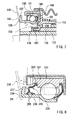
Fig. 1] Fig. 1 is a vertical cross-sectional view showing a clutch release bearing apparatus according to Example 1 of the present invention. - [
Fig. 2] Fig. 2 is also a vertical cross-sectional view showing a clutch release bearing in an enlarged scale. - [
Fig. 3] Fig. 3 is also a vertical cross-sectional view showing a relationship between an inner ring of the clutch release bearing and a second bent portion at a distal end of an intermediate cylinder portion of a cover member in an enlarged scale. - [
Fig. 4] Fig.4 is a vertical cross-sectional view showing a relationship between the inner ring of the clutch release bearing and the second bent portion at the distal end of the intermediate cylinder portion of the cover member according to Example 2 of the present invention in an enlarged scale. - [
Fig. 5] Fig.5 is a vertical cross-sectional view showing a relationship between the inner ring of the clutch release bearing and the second bent portion at the distal end of the intermediate cylinder portion of the cover member according to Example 3 of the present invention in an enlarged scale. - [
Fig. 6] Fig. 6 is a vertical cross-sectional view showing a state in which a sealing member is assembled between the inner ring and an outer ring of the clutch release bearing apparatus according to Example 4 of the present invention in an enlarged scale. - [
Fig. 7] Fig. 7 is an explanatory drawing showing a clutch release bearing apparatus in the related art. - [
Fig. 8] Fig. 8 is an explanatory drawing showing another clutch release bearing apparatus in the related art. - Modes for carrying out the present invention will be described according to examples.
- Example 1 of the present invention will be described in reference to
Fig. 1 to Fig.3 .
A clutch release bearing apparatus according to Example 1 exemplified here is a case of a hydraulic type clutch release bearing apparatus disposed between an annular piston operated by a hydraulic pressure and a diaphragm spring.
As shown inFig. 1 , anannular cylinder space 16 is formed between aninternal cylinder body 10 to be assembled to an outer peripheral surface of a clutch main shaft 1 and anexternal cylinder body 15, and anannular piston 20 to be operated by the hydraulic pressure supplied into thecylinder space 16 is fitted and inserted into thecylinder space 16.
Anannular groove 21 is formed on an outer peripheral surface of the distal end of a projecting portion of theannular piston 20 projecting from thecylinder space 16. - As shown in
Fig. 1 and Fig. 2 , the clutch release bearing apparatus disposed between theannular piston 20 and adiaphragm spring 40 includes a clutch release bearing 30 and acover member 50.
The clutch release bearing 30 includes anouter ring 31, aninner ring 35 arranged on an inner periphery of theouter ring 31 concentrically, andballs 32 as a plurality of rolling bodies disposed so as to be capable of rolling in a state of being held in an annular space between theouter ring 31 and theinner ring 35 by aholder 33.
Also, an extendingcylinder portion 36 extending in the axial direction toward an radially insideportion 41 of thediaphragm spring 40 is formed at one end (on the side opposing the diaphragm spring 40) of theinner ring 35, and aflange portion 37 having apressing surface 38 which presses the radially insideportion 41 of thediaphragm spring 40 projects radially outward at an extending end of the extendingcylinder portion 36. - As shown in
Fig. 2 , thecover member 50 configured to cover and hold an outer peripheral surface of theouter ring 31 of the clutch release bearing 30 includes aflange member 60 connected on the radially inside thereof to theannular piston 20, and acylindrical body 51 configured to cover the outer peripheral surface of theouter ring 31 of the clutch release bearing 30 on the radially outside thereof.
In Example 1, theflange member 60 which constitutes thecover member 50 and thecylindrical body 51 are separate components (two components) and are assembled to each other. - The
cylindrical body 51 is formed into a press work (drawing work) of a metal plate (steel plate) thinner than theflange member 60, and includes a cylindricalcylinder body portion 52 having an inner diameter slightly smaller than the outer diameter of theouter ring 31, a small-diametercylinder end portion 53 formed at one end portion of thecylinder body portion 52 so as to have a cylinder length substantially the same as the thickness of theflange member 60 and be reduced in diameter, and having an inner diameter slightly smaller than the outer diameter of the flange member 60 (the outer diameter of a radially outsideflange portion 61 described next), and an annularend wall portion 54 bent radially inward from an end edge of the small-diametercylinder end portion 53 integrally, thereby being formed into a stepped cylindrical shape.
Then, theflange member 60 is fixedly press-fitted into the small-diametercylinder end portion 53 of thecylindrical body 51 with a predetermined interference, and one side surface of theflange member 60 comes into abutment with an inside surface of the annularend wall portion 54. - Also, the
outer ring 31 is fixedly press-fitted into thecylinder body portion 52 of thecylindrical body 51 with a predetermined interference, and thecylindrical body 51, theflange member 60, theouter ring 31 are integrated with each other in a state in which one end surface of theouter ring 31 is in abutment with the other side surface of theflange member 60. - As shown in
Fig. 2 , theflange member 60 is formed into a press work of a thick metal plate (steel plate), and includes the radially outsideflange portion 61, a firstbent portion 62, anintermediate cylinder portion 63, a second bent portion (which corresponds to a bent portion in the present invention) 64, a radially insideflange portion 65 so as to be continued integrally.
The radially outsideflange portion 61 is fixedly press-fitted into the small-diametercylinder end portion 53 of thecylindrical body 51 along a radially outside surface with a predetermined interference, and extends from one end surface of theouter ring 31 of the clutch release bearing 30 to one end surface of theinner ring 35 toward a radially center side.
The firstbent portion 62 is bent from a radially inner end of the radially outsideflange portion 61 toward an inner peripheral surface of theinner ring 35 of the clutch release bearing 30 at a predetermined radius of curvature.
Theintermediate cylinder portion 63 extends from an end edge of the firstbent portion 62 along the inner peripheral surface of theinner ring 35 with an annular space S set with respect to the inner peripheral surface of theinner ring 35 of the clutch release bearing 30 and having a gap dimension A.
Also, the gap dimension A of the annular space S is preferably set to a range from 0.3 mm to 0.5 mm. - As shown in
Fig. 2 , the secondbent portion 64 is bent from an end edge of theintermediate cylinder portion 63 toward the center side at a predetermined radius of curvature.
The radially insideflange portion 65 extends from an end edge of the secondbent portion 64 toward the radially center side, and a radially inner end, which is an end of extension, is arranged with an annular gap for center alignment with a bottom surface (radially outside surface) of theannular groove 21 of theannular piston 20. Then, a disc-spring shaped aligningspring 25 is disposed between anend wall surface 23 of theannular groove 21 and the radially insideflange portion 65, and one side surface of the radially insideflange portion 65 comes into abutment with apressing surface 22 of theannular groove 21 by a resilient force of the aligningspring 25.
In other words, a center mounting portion to be assembled to theannular piston 20 is formed at a center portion of the radially insideflange portion 65. - In other words, when a deviation in the radial direction is generated between the
diaphragm spring 40 and the clutch release bearing 30, the clutch release bearing 30 is relatively moved in the radial direction via the aligningspring 25 with respect to thediaphragm spring 40, so that the clutch release bearing 30 is aligned with thediaphragm spring 40.
As shown inFig. 1 , disposed between aspring receiving member 70 disposed along theflange member 60 and theexternal cylinder body 15 is a pressurizingspring 75 configured to press the clutch release bearing 30 toward thediaphragm spring 40 together with thecover member 50. - As shown in
Fig. 3 , a cylindricalperipheral wall surface 90 extending in parallel with the axial direction is formed on the inner peripheral surface of theinner ring 35 of the clutch release bearing 30 over a portion from one end side corresponding to the radially outsideflange portion 61 of thecover member 50 to an end edge of theintermediate cylinder portion 63. In addition, a guidingsurface 91 which is formed into a tapered shape and a curved shape (including an arcuate shape) so as to increase in diamter gradually from an end edge of the cylindricalperipheral wall surface 90 toward an inner peripheral surface of the extendingcylinder portion 36 is formed into the inner peripheral surface of theinner ring 35. Then, the muddy water or the like flowing from the radially insideflange portion 65 side of thecover member 50 along the secondbent portion 64 is guided toward the distal end side of the extendingcylinder portion 36 of theinner ring 35 by the guidingsurface 91. - Also, as shown in
Fig. 3 , a starting point P of the guidingsurface 91 on the side of the cylindricalperipheral wall surface 90 of the inner peripheral surface of theinner ring 35 is preferably set at the same position as a bending starting point Q of the secondbent portion 64 on the side of theintermediate cylinder portion 63 of the cover member (the flange member 60) 50, or on the back side thereof.
For example, a distance dimension B between the starting point P and the bending starting point Q is preferably set to a range from 0.0 mm to 2.0 mm.
Also, as shown inFig. 3 , another cylindricalperipheral wall surface 94 having a diameter larger than the cylindricalperipheral wall surface 90 of theinner ring 35 is formed on an inner peripheral surface of the extendingcylinder portion 36. Then, the guidingsurface 91 is continuously connecting the both cylindrical peripheral wall surfaces 90, 94. In addition, an end point R of the guidingsurface 91, which is a boundary with respect to the guidingsurface 94 of the extendingcylinder portion 36, is preferably set at the same position as aside surface 65a of the radially insideflange portion 65 or on the back side thereof.
For example, a distance dimension D between the end point R and theside surface 65a of the radially insideflange portion 65 is preferably set to a range from 0.0 mm to 1.2 mm.
Also, a spacing dimension C between the cylindricalperipheral wall surface 90 of theinner ring 35 and the inner peripheral surface of the extendingcylinder portion 36 is preferably set to a range from 0.9 mm to 1.3 mm. - Also, as shown in
Fig. 2 , both sealingmembers outer ring 31 and theinner ring 35 of the clutch release bearing 30.
Also, the sealingmember 80 is formed at a radially outer end portion of the sealingmember 80 to be assembled between an outer peripheral surface of one end portion of theinner ring 35 and an inner peripheral surface of one end portion of theouter ring 31 with a radially outside fixedportion 81 to be fixed into a groove on the inner peripheral surface of the one end side of theouter ring 31 in a resiliently compressed manner, and at a radially inner end portion with aseal lip 83 made up of a resilient member which comes into contact with or approaches the end surface and the outer peripheral surface of one end portion of theinner ring 35 in a bifurcated form. - The clutch release bearing apparatus according to Example 1 is configured as described above.
Therefore, when the hydraulic pressure is supplied into thecylinder space 16 on the basis of a press-down operation of a clutch pedal (not shown), theannular piston 20 is pressed outward.
Then, the radially insideflange portion 65 of theflange member 60 of thecover member 50 is pressed against thepressing surface 22 of an inner wall surface on one side of theannular groove 21 of theannular piston 20, so that the clutch release bearing 30 is moved axially leftward together with thecover member 50. Then, the radially insideportion 41 of thediaphragm spring 40 is pressed by the annular pressingportion 36 at an end portion of theinner ring 35 of the clutch release bearing 30, and a clutch, not shown, is activated (disconnected). - And now, during the travel of the vehicle, there is a case where muddy water or the like entered into the clutch housing is splashed around by the
diaphragm spring 40 and the muddy water or the like flows from the side of the radially insideflange portion 65 of thecover member 50 along the second bent portion 64 (see arrows inFig. 3 ).
The muddy water or the like flowed along the secondbent portion 64 of thecover member 50 is guided by the guidingsurface 91 on the inner peripheral surface of theinner ring 35 and flows toward the distal end side of the extendingcylinder portion 36 of theinner ring 35. In particular, when theinner ring 35 is rotated, it is guided along the guidingsurface 91 with an action of a centrifugal force thereof and flows quickly.
In other words, in cooperation of the secondbent portion 64 of thecover member 50 and the guidingsurface 91 of theinner ring 35, the muddy water or the like can be guided toward the distal end side of the extendingcylinder portion 36 of theinner ring 35.
Consequently, the entry of the muddy water or the like into the annular space S set between the inner peripheral surface of theinner ring 35 and theintermediate cylinder portion 63 of thecover member 50 can be restrained, so that improvement of watertightness is achieved. - Also, in Example 1, the starting point P of the guiding
surface 91 on the side of the cylindricalperipheral wall surface 90 of the inner peripheral surface of theinner ring 35 is set at the same position as the bending starting point Q of the secondbent portion 64 on the side of theintermediate cylinder portion 63 of thecover member 50, or on the back side thereof Therefore, the muddy water or the like flowing along the secondbent portion 64 of thecover member 50 can be desirably guided by the guidingsurface 91 of theinner ring 35, and prevention of the entry of the muddy water or the like into the annular space S between the inner peripheral surface of theinner ring 35 and theintermediate cylinder portion 63 of thecover member 50 is effectively achieved. - Also, in Example 1, another cylindrical
peripheral wall surface 94 having a diameter larger than the cylindricalperipheral wall surface 90 of theinner ring 35 is formed on the inner peripheral surface of the extendingcylinder portion 36. Then, the guidingsurface 91 is continuously connecting the both cylindrical peripheral wall surfaces 90, 94. In addition, the end point R of the guidingsurface 91, which is a boundary with respect to the cylindricalperipheral wall surface 94 of the extendingcylinder portion 36, is set at the same position as theside surface 65a of the radially insideflange portion 65 or on the back side thereof. Therefore, the muddy water or the like flowing along theside surface 65a of the radially insideflange portion 65 and reaching the inner peripheral surface of theinner ring 35 is guided desirably by the guidingsurface 91 and flows toward the distal end side of the extendingcylinder portion 36 of theinner ring 35 without being hindered by the guidingsurface 91. Consequently, the entry of the muddy water or the like into the annular space S set between the inner peripheral surface of theinner ring 35 and theintermediate cylinder portion 63 can be restrained further desirably. - Subsequently, referring now to
Fig. 4 , Example 2 of the present invention will be described.
As shown inFig. 4 , in Example 2, a guidingsurface 91a having a tapered shape formed continuously at a distal end of the cylindricalperipheral wall surface 90 of the inner peripheral surface of theinner ring 35 is formed to be inclined so as to gradually increase in diameter from an end edge of the cylindricalperipheral wall surface 90 to a distal end of the extendingcylinder portion 36.
Then, the muddy water or the like flowing from the radially insideflange portion 65 side of thecover member 50 along the secondbent portion 64 is guided toward the distal end side of the extendingcylinder portion 36 of theinner ring 35 by the guidingsurface 91a. - Also, as described also in Example 1, a starting point P' of the guiding
surface 91a on the side of the cylindricalperipheral wall surface 90 of the inner peripheral surface of theinner ring 35 is preferably set at the same position as the bending starting point Q of the secondbent portion 64 on the side of theintermediate cylinder portion 63 of the cover member (flange member 60,) 50 or on the back side thereof
In other words, a distance dimension B' between the starting point P' and the bending starting point Q is preferably set to a range from 0.0 mm to 2.0 mm. - Other configurations of Example 2 are the same as those in Example 1. Therefore, the same reference numerals are assigned to the same components, and description thereof is omitted.
Therefore, the same effects and advantages as those in Example 1 are achieved also in Example 2. - Subsequently, referring now to
Fig. 5 , Example 3 of the present invention will be described.
As shown inFig. 5 , adepressed portion 95 and a projectingportion 96 which constitute a non-contact seal portion by approaching each other are formed respectively between the inner peripheral surface of theinner ring 35 and an outer peripheral surface of theintermediate cylinder portion 63 of thecover member 50 which constitutes the annular space S.
Also, the projectingportion 96 has an inner diameter slightly larger than the outer diameter of theintermediate cylinder portion 63, and thedepressed portion 95 is set to have dimensions to form a predetermined gap (the gap which functions as the non-contact seal portion) with respect to the inner diameter of the projectingportion 96. - In Example 3, as shown in
Fig. 5 , the annular projectingportion 96 is formed on an inner peripheral surface of the one end portion of theinner ring 35, and the annulardepressed portion 95 is formed on the outer peripheral surface of one end portion of theintermediate cylinder portion 63 of thecover member 50.
Also, considering the assembleability between theinner ring 35 and the extendingcylinder portion 36 of thecover member 50, an inner diameter dimension F of the projectingportion 96 is set to be larger than an outer diameter dimension E of theintermediate cylinder portion 63, even though it is a small extent.
In addition, the gap dimension between the radially inside surface of the projectingportion 96 and the radially outside surface of thedepressed portion 95 is preferably set to a range from 0.05 mm to 0.25 mm (preferably, on the order of 0.15 mm). - Other configurations of Example 3 are the same as those in Example 1. Therefore, the same reference numerals are assigned to the same components, and description thereof is omitted.
Therefore, the same effects and advantages as those in Example 1 are achieved also in Example 3.
In particular, in Example 3, thedepressed portion 95 and the projectingportion 96 which constitute the non-contact seal portion are formed respectively between the inner peripheral surface of theinner ring 35 and the outer peripheral surface of theintermediate cylinder portion 63 of thecover member 50. Therefore, granted that part of the muddy water or the like flowing from the radially insideflange portion 65 side of thecover member 50 along the secondbent portion 64 enters the annular space S between the inner peripheral surface of theinner ring 35 and the outer peripheral surface of theintermediate cylinder portion 63 of thecover member 50, the muddy water or the like is stopped by the non-contact seal portion made up of thedepressed portion 95 and the projectingportion 96 and further entry thereof can be prevented. - Subsequently, referring now to
Fig. 6 , Example 4 of the present invention will be described.
In Example 4, a sealingmember 85 to be assembled between an outer peripheral surface of the extendingcylinder portion 36 of theinner ring 35 and an outer peripheral surface of one end portion of theouter ring 31, which is one of both sealing members to be assembled to both end portions between theouter ring 31 and theinner ring 35 of the clutch release bearing 30 as shown inFig. 6 , will be described in detail.
The sealingmember 85 is provided at a radially outer end portion of the sealingmember 85 with a radially outside fixedportion 86 to be fixed to theouter ring 31 and at a radially inner end portion thereof with acontact lip 88 which comes into resilient contact with an outer peripheral surface of the extendingcylinder portion 36 of theinner ring 35.
Furthermore, the sealingmember 85 is formed with anon-contact lip 89 which constitutes the non-contact seal portion in cooperation with theflange portion 37 of theinner ring 35. - Also, in Example 4, the sealing
member 85 integrally includes acore metal 85a formed of a metal plate bent into an L-shape in vertical cross section, and aresilient member 85b formed of soft resin, rubber, or the like and formed so as to cover thecore metal 85a.
Also, theresilient member 85b integrally includes the radially outside fixedportion 86 formed on the radially outer end portion of the sealingmember 85, acoating layer 87 configured to cover an outside surface of thecore metal 85a, thecontact lip 88 as a first lip formed on the radially inner end portion of the sealingmember 85, and thenon-contact lip 89 as a second lip projecting axially from one side surface of thecoating layer 87.
Then, the radially outside fixedportion 86 of the sealingmember 85 is resiliently compressed and fixedly assembled by being press-fitted into anannular groove 31a formed on an inner peripheral surface of one end portion of theouter ring 31. In this assembled state, thecontact lip 88 comes into resilient contact with the outer peripheral surface of the extendingcylinder portion 36 of theinner ring 35, and thenon-contact lip 89 approaches an outer peripheral surface of theflange portion 37 of theinner ring 35 and constitutes the non-contact seal portion in cooperation with theflange portion 37. - Also, in Example 4, a gap dimension J between the
non-contact lip 89 and the outer peripheral surface of theflange portion 37 of theinner ring 35 is preferably set to a range from 0.05 mm to 0.25 mm. The applicant has confirmed that the practical effect is further desirable when the gap dimension J is set to a value on the order of 0.15. With this configuration, even when variations in manufacture or assembly of the sealingmember 85 exist, the non-contact seal portion can be formed easily with respect to the outer peripheral surface of theflange portion 37 of theinner ring 35.
In other words, if the gap dimension J is set to be smaller than 0.05, it is assumed that thenon-contact lip 89 comes into contact with the outer peripheral surface of theflange portion 37 of theinner ring 35 due to the variations in manufacture or assembly of the sealingmember 85, and if the gap dimension J is set to be larger than 0.25 mm, the function as the non-contact seal portion is lowered. However, by setting the gap dimension J as described above, variations in manufacture or assembly of the sealingmember 85 can be absorbed and the function as the non-contact seal portion is desirably achieved. - Also, in Example 4, as shown in
Fig. 6 , an overlapped amount K between thenon-contact lip 89 and the outer peripheral surface of theflange portion 37 of theinner ring 35 is preferably set to a range from 0.28 mm to 1.12 mm. The applicant has confirmed that the practical effect is further desirable when the overlapped amount K is set to a value on the order of 0.6 mm. With this configuration, even when variations in manufacture or assembly of the sealingmember 85 exist, the non-contact seal portion can be formed easily.
In other words, the overlapped amount K is set to be smaller than 0.28 mm, the overlapped amount K is not sufficient due to the variations in manufacture or assembly of the sealingmember 85 and hence the function as the non-contact seal portion is lowered, and if the overlapped amount K is set to be larger than 1.12 mm, it is assumed that thenon-contact lip 89 is liable to be deformed inadvertently, and hence comes into contact with the outer peripheral surface of theflange portion 37 of theinner ring 35. However, by setting the overlapped amount K as described above, variations in manufacture or assembly of the sealingmember 85 can be absorbed, and the function as the non-contact seal portion is desirably achieved. - Also, as shown in
Fig. 6 , one side surface of thecoating layer 87 of the sealingmember 85 is arranged in the vicinity of an inside surface of theflange portion 37 of theinner ring 35 opposing the one side surface, and a second non-contact seal portion continuing to the non-contact seal portion is formed at the corresponding portion.
In other words, in a state in which the sealingmember 85 is assembled, a gap dimension L between the one side surface of thecoating layer 87 and the inside surface of theflange portion 37 of theinner ring 35 is desirably set to a range from 0.10 mm to 0.25 mm.
Other configurations of Example 4 are the same as those in Example 1. Therefore, the same reference numerals are assigned to the same components, and description thereof is omitted. - Therefore, in the clutch release bearing apparatus according to Example 4 as well, the same effects and advantages as those in Example 1 are achieved.
In particular, in Example 4, the sealingmember 85 to be assembled between the outer peripheral surface of the extendingcylinder portion 36 of theinner ring 35 and the outer peripheral surface of the one end portion of theouter ring 31 is formed with thenon-contact lip 89, and the non-contact seal portion is formed in cooperation with theflange portion 37 of theinner ring 35. Accordingly, even when the muddy water or the like entered into the clutch housing during the travel of a vehicle is splashed by the diaphragm spring, and enter toward the extendingcylinder portion 36 of theinner ring 35, it is stopped by the non-contact seal portion in cooperation between thecontact lip 89 of the sealingmember 85 and theflange portion 37 of theinner ring 35, so that the entry thereof into the interior of the bearing is prevented.
Granted that part of the muddy water or the like has passed through the non-contact seal portion, it is stopped by thecontact lip 88 which is in resilient contact with the outer peripheral surface of the extendingcylinder portion 36 of theinner ring 35.
Consequently, the reduction of the torque loss is achieved by restraining a resilient press-contact force (interference) of thecontact lip 88 with respect to the outer peripheral surface of the extendingcylinder portion 36 of theinner ring 35, and improvement of the sealing properties (watertightness, dustproof resistant property, etc.) is achieved. - Also, in Example 4, the non-contact seal portion can be formed easily by bringing the
non-contact lip 89 projecting axially from one side surface of thecoating layer 87 of the sealingmember 85 to the vicinity of the outer peripheral surface of theflange portion 37 of theinner ring 35.
Also, in Example 4, the second non-contact seal portion continuing in series with the non-contact seal portion configured with thenon-contact lip 89 can be formed by arranging the one side surface of thecoating layer 87 of the sealingmember 85 to the vicinity of the inside surface of theflange portion 37 of theinner ring 35, so that further improvement of the watertightness and dustproof-resistant property is achieved. - The present invention is not limited to Examples 1 to 4, and may be implemented in various modes without departing the scope of the present invention.
For example, in the above-described Example 1, the case in which thecover member 50 is made up of two component, namely, theflange member 60 and thecylindrical body 51 has been described. However, the present invention can be implemented even when it is made up of one component.
Also, in the above-described Example 4, the case where the first lip of the sealingmember 85 is thecontact lip 88 and the second lip is thenon-contact lip 89 has been described. However, the first lip and the second lip of the present invention are not limited to the contact lip, the non-contact lip. -
- 30
- clutch release bearing
- 31
- outer ring
- 32
- ball (rolling body)
- 35
- inner ring
- 36
- extending cylinder portion
- 40
- diaphragm spring
- 50
- cover member
- 60
- flange member
- 61
- radially outside flange portion
- 63
- intermediate cylinder portion
- 64
- second bent portion (bent portion)
- 85
- sealing member
- 86
- radially outside fixed portion
- 88
- contact lip (first lip)
- 89
- non-contact lip (second lip)
- 90
- cylindrical peripheral wall surface
- 91
- guiding surface
Claims (12)
- A clutch release bearing apparatus comprising: an outer ring, an inner ring, and a rolling body disposed between the outer ring and the inner ring, characterized in that
the outer ring includes a radially outside flange portion extending from one end surface of the outer ring over one end of the inner ring toward a radially center side, an intermediate cylinder portion extending from a radially inner end of the radially outside flange portion along the inner peripheral surface of the inner ring within an annular space set with respect to an inner peripheral surface of the inner ring, a bent portion bent from an end edge of the intermediate cylinder portion toward the radially center side at a predetermined radius of curvature, and a radially inside flange portion extending from an end edge of the bent portion toward the radially center side,
the inner ring is formed with an extending cylinder portion extending in an axial direction at the other end thereof, and
the inner ring includes on the inner peripheral surface thereof a cylindrical peripheral wall surface extending axially in parallel to a portion from one end side corresponding to the radially outside flange portion to an end edge of the intermediate cylinder portion and a guiding surface formed into an inclined state or a curved state by being increased gradually in diameter from an end edge of the cylindrical peripheral wall surface toward the extending cylinder portion continuously to each other. - A clutch release bearing apparatus having an outer ring, an inner ring, a rolling body disposed between the outer ring and the inner ring, comprising:a radially outside flange portion connected directly or indirectly to the outer ring and extending from one end surface of the outer ring over the other end surface of the inner ring toward a radially center side, an intermediate cylinder portion extending from a radially inner end of the radially outside flange portion along the inner peripheral surface of the inner ring within an annular space set with respect to an inner peripheral surface of the inner ring, a bent portion bent from an end edge of the intermediate cylinder portion toward the radially center side at a predetermined radius of curvature, and a radially inside flange portion extending from an end edge of the bent portion toward the radially center side,a center mounting portion arranged at a center portion of the radially inside flange portion and assembled to a piston of the clutch release bearing apparatus,a cover member forming an annular space in which an external cylinder of the clutch release bearing apparatus can be arranged between the intermediate cylinder portion and the piston; characterized in thatthe inner ring is formed with an extending cylinder portion extending in an axial direction at the other end thereof,an inner peripheral surface of the inner ring includes a cylindrical peripheral wall surface extending axially in parallel to a portion from one end side corresponding to the radially outside flange portion to an end edge of the intermediate cylindrical portion and a guiding surface formed into an inclined state or a curved state by being increased gradually in diameter from an end edge of the cylindrical peripheral wall surface toward the extending cylinder portion continuously to each other.
- The clutch release bearing apparatus according to Claim 1 or 2, characterized in that
a starting point of the guiding surface of the inner peripheral surface of the inner ring on the side of the cylindrical peripheral wall surface is set to the same position as a bending starting point of the bent portion on the side of the intermediate cylinder portion or on the back side thereof in the axial direction. - The clutch release bearing apparatus according to any one of Claims 1 to 3,
characterized in that another cylindrical peripheral wall surface having a diameter larger than the cylindrical peripheral wall surface of the inner ring is formed on an inner peripheral surface of the extending end of the extending cylinder portion, and
the guiding surface is continuously connecting the both cylindrical peripheral wall surfaces, and an end point of the guiding surface, which is a boundary between the guiding surface and the another guiding surface, is positioned at the same position as a side surface of the radially inside flange portion or on the back side thereof - The clutch release bearing apparatus according to any one of Claims 1 to 4,
characterized in that part of the cylindrical peripheral wall surface of the inner ring and part of the intermediate cylinder portion opposing thereto are formed with a depression portion and a projecting portion which approach with respect to each other to form a non-contact seal portion. - The clutch release bearing apparatus according to Claim 5, characterized in that
the part of the cylindrical peripheral wall surface of the inner ring is formed with a projecting portion having an inner diameter slightly larger than the outer diameter of the intermediate cylinder portion, and an outer peripheral surface of the intermediate cylinder portion to which the projecting portion opposes is formed with a depressed portion at a gap set with respect to the inner diameter of the projecting portion. - A clutch release bearing apparatus comprising: an outer ring, an inner ring, a rolling body disposed between the outer ring and the inner ring, and a sealing member disposed between the outer ring and the inner ring, characterized in that
the inner ring includes an extending cylinder portion extending from one end of the inner ring in the axial direction and a flange portion projecting radially outward formed at an extending end of the extending cylinder portion, and
the sealing member includes a radially outside fixed portion to be fixed to the outer ring, a first lip producing a sealing effect on an outer peripheral surface portion of the extending cylinder portion, and a second lip producing the sealing effect in cooperation with the flange portion of the inner ring. - The clutch release bearing apparatus according to Claim 7, characterized in that
the second lip projects from one side surface of the sealing member in the axial direction and is positioned in the vicinity of an outer peripheral surface of the flange portion of the inner ring. - The clutch release bearing apparatus according to Claim 8, characterized in that a gap dimension between the second lip and the outer peripheral surface of the flange portion is set to a range from 0.05 mm to 0.25 mm.
- The clutch release bearing apparatus according to Claim 8 or 9, characterized in that
an overlapped amount between the second lip and the outer peripheral surface of the flange portion is set to a range from 0.28 mm to 1.12 mm. - The clutch release bearing apparatus according to any one of Claims 7 to 10, characterized in that
the first lip is formed so as to come into resilient contact with the outer peripheral surface portion of the extending cylinder portion. - The clutch release bearing apparatus according to any one of Claims 7 to 11, characterized in that
the sealing member includes a portion opposing an inside surface of the flange portion in the vicinity thereof so as to produce the sealing effect in cooperation with the inside surface of the flange portion.
Applications Claiming Priority (3)
| Application Number | Priority Date | Filing Date | Title |
|---|---|---|---|
| JP2008256563A JP2010084903A (en) | 2008-10-01 | 2008-10-01 | Clutch release bearing device |
| JP2008256562A JP5243911B2 (en) | 2008-10-01 | 2008-10-01 | Clutch release bearing device |
| PCT/JP2009/067035 WO2010038781A1 (en) | 2008-10-01 | 2009-09-30 | Clutch release bearing device |
Publications (3)
| Publication Number | Publication Date |
|---|---|
| EP2336589A1 true EP2336589A1 (en) | 2011-06-22 |
| EP2336589A4 EP2336589A4 (en) | 2012-08-22 |
| EP2336589B1 EP2336589B1 (en) | 2014-09-10 |
Family
ID=42073540
Family Applications (1)
| Application Number | Title | Priority Date | Filing Date |
|---|---|---|---|
| EP09817813.0A Active EP2336589B1 (en) | 2008-10-01 | 2009-09-30 | Clutch release bearing device |
Country Status (3)
| Country | Link |
|---|---|
| EP (1) | EP2336589B1 (en) |
| CN (1) | CN102224352A (en) |
| WO (1) | WO2010038781A1 (en) |
Cited By (3)
| Publication number | Priority date | Publication date | Assignee | Title |
|---|---|---|---|---|
| FR3008149A1 (en) * | 2013-07-03 | 2015-01-09 | Skf Ab | BEARING BEARING, IN PARTICULAR FOR A CLUTCH STOP DEVICE |
| DE102024200218A1 (en) * | 2024-01-10 | 2025-07-10 | Volkswagen Aktiengesellschaft | Method for producing a bearing outer ring, bearing outer ring and rolling bearing |
| US12553473B2 (en) | 2021-05-07 | 2026-02-17 | Jtekt Corporation | Thrust bearing |
Families Citing this family (2)
| Publication number | Priority date | Publication date | Assignee | Title |
|---|---|---|---|---|
| US9322440B2 (en) * | 2014-02-18 | 2016-04-26 | Gm Global Technology Operations Inc. | Clutch cooling mechanism |
| CN103994156B (en) * | 2014-05-22 | 2016-09-07 | 杭州诚信汽车轴承有限公司 | The aligning-type Hydraulic Pressure Declutched Bearing Assembly that inner ring rotates |
Family Cites Families (11)
| Publication number | Priority date | Publication date | Assignee | Title |
|---|---|---|---|---|
| JPS4427288Y1 (en) * | 1965-07-01 | 1969-11-14 | ||
| JPS5071650U (en) * | 1973-11-05 | 1975-06-24 | ||
| JPS59191428U (en) * | 1983-06-08 | 1984-12-19 | 株式会社不二越 | Sealing mechanism of rolling bearings |
| JPS6136734U (en) * | 1984-08-07 | 1986-03-07 | マツダ株式会社 | Automotive clutch release bearing device |
| GB2166511A (en) * | 1984-11-02 | 1986-05-08 | Rhp Group Plc | Improvements in clutch release mechanisms |
| JPS6263420U (en) * | 1985-10-11 | 1987-04-20 | ||
| JPH0628359A (en) | 1992-06-02 | 1994-02-04 | Mitsui Mining & Smelting Co Ltd | Truck transportation fare calculation system |
| DE29608918U1 (en) * | 1996-05-17 | 1996-08-14 | INA Wälzlager Schaeffler KG, 91074 Herzogenaurach | Guide sleeve of a slave cylinder, the ring flange of which is attached to the outside of the pressure housing by caulking |
| DE19622773C1 (en) * | 1996-06-07 | 1997-05-07 | Fichtel & Sachs Ag | Slave cylinder for friction clutch actuation |
| JP4370659B2 (en) | 1999-03-09 | 2009-11-25 | 日本精工株式会社 | Seal and clutch release bearing device |
| JP3701262B2 (en) * | 2002-06-14 | 2005-09-28 | 日信工業株式会社 | Clutch device |
-
2009
- 2009-09-30 WO PCT/JP2009/067035 patent/WO2010038781A1/en not_active Ceased
- 2009-09-30 CN CN2009801465018A patent/CN102224352A/en active Pending
- 2009-09-30 EP EP09817813.0A patent/EP2336589B1/en active Active
Cited By (3)
| Publication number | Priority date | Publication date | Assignee | Title |
|---|---|---|---|---|
| FR3008149A1 (en) * | 2013-07-03 | 2015-01-09 | Skf Ab | BEARING BEARING, IN PARTICULAR FOR A CLUTCH STOP DEVICE |
| US12553473B2 (en) | 2021-05-07 | 2026-02-17 | Jtekt Corporation | Thrust bearing |
| DE102024200218A1 (en) * | 2024-01-10 | 2025-07-10 | Volkswagen Aktiengesellschaft | Method for producing a bearing outer ring, bearing outer ring and rolling bearing |
Also Published As
| Publication number | Publication date |
|---|---|
| WO2010038781A1 (en) | 2010-04-08 |
| EP2336589A4 (en) | 2012-08-22 |
| CN102224352A (en) | 2011-10-19 |
| EP2336589B1 (en) | 2014-09-10 |
Similar Documents
| Publication | Publication Date | Title |
|---|---|---|
| JP3795921B2 (en) | Fluid-controlled clutch release bearing for a diaphragm clutch, especially for automobiles, having a guide sleeve | |
| EP2336589B1 (en) | Clutch release bearing device | |
| US7905785B2 (en) | Sealing assembly | |
| WO2015093376A1 (en) | Release bearing and clutch release bearing device | |
| US7648144B2 (en) | Sealing device | |
| CN109073086B (en) | Dust-proof sealing part | |
| EP2405153A2 (en) | Clutch release bearing device | |
| EP2085633B1 (en) | Clutch release bearing | |
| EP2984358A1 (en) | Large sealed self aligning rolling bearing with improved sealing | |
| JP2011196503A (en) | Sealing device assembly for rolling bearing | |
| JP4843941B2 (en) | Sealing device | |
| JP5103345B2 (en) | Clutch release bearing device | |
| JP5243911B2 (en) | Clutch release bearing device | |
| WO2008077021A1 (en) | Formed grease cover retention feature | |
| JP5018498B2 (en) | Hydraulic clutch release bearing device | |
| JP2010084892A (en) | Disc spring assembly | |
| JP2017223253A (en) | Manufacturing method of wheel bearing device | |
| EP2085629A1 (en) | Sealing device, rolling bearing, and rolling bearing for wheel | |
| JP2010084903A (en) | Clutch release bearing device | |
| JP2007024205A (en) | Oil seal | |
| JPH0559056U (en) | Oil seal | |
| CN117307716A (en) | Sealing means | |
| CN112013115B (en) | Sealing device | |
| JP2009168178A5 (en) | ||
| CN108869567A (en) | Retaining ring and clutch release system |
Legal Events
| Date | Code | Title | Description |
|---|---|---|---|
| PUAI | Public reference made under article 153(3) epc to a published international application that has entered the european phase |
Free format text: ORIGINAL CODE: 0009012 |
|
| 17P | Request for examination filed |
Effective date: 20110412 |
|
| AK | Designated contracting states |
Kind code of ref document: A1 Designated state(s): AT BE BG CH CY CZ DE DK EE ES FI FR GB GR HR HU IE IS IT LI LT LU LV MC MK MT NL NO PL PT RO SE SI SK SM TR |
|
| AX | Request for extension of the european patent |
Extension state: AL BA RS |
|
| DAX | Request for extension of the european patent (deleted) | ||
| A4 | Supplementary search report drawn up and despatched |
Effective date: 20120720 |
|
| RIC1 | Information provided on ipc code assigned before grant |
Ipc: F16D 23/14 20060101AFI20120716BHEP |
|
| GRAP | Despatch of communication of intention to grant a patent |
Free format text: ORIGINAL CODE: EPIDOSNIGR1 |
|
| INTG | Intention to grant announced |
Effective date: 20140320 |
|
| GRAS | Grant fee paid |
Free format text: ORIGINAL CODE: EPIDOSNIGR3 |
|
| GRAA | (expected) grant |
Free format text: ORIGINAL CODE: 0009210 |
|
| AK | Designated contracting states |
Kind code of ref document: B1 Designated state(s): AT BE BG CH CY CZ DE DK EE ES FI FR GB GR HR HU IE IS IT LI LT LU LV MC MK MT NL NO PL PT RO SE SI SK SM TR |
|
| REG | Reference to a national code |
Ref country code: GB Ref legal event code: FG4D |
|
| REG | Reference to a national code |
Ref country code: CH Ref legal event code: EP |
|
| REG | Reference to a national code |
Ref country code: IE Ref legal event code: FG4D |
|
| REG | Reference to a national code |
Ref country code: AT Ref legal event code: REF Ref document number: 686854 Country of ref document: AT Kind code of ref document: T Effective date: 20141015 |
|
| REG | Reference to a national code |
Ref country code: DE Ref legal event code: R096 Ref document number: 602009026641 Country of ref document: DE Effective date: 20141023 |
|
| PG25 | Lapsed in a contracting state [announced via postgrant information from national office to epo] |
Ref country code: LT Free format text: LAPSE BECAUSE OF FAILURE TO SUBMIT A TRANSLATION OF THE DESCRIPTION OR TO PAY THE FEE WITHIN THE PRESCRIBED TIME-LIMIT Effective date: 20140910 Ref country code: GR Free format text: LAPSE BECAUSE OF FAILURE TO SUBMIT A TRANSLATION OF THE DESCRIPTION OR TO PAY THE FEE WITHIN THE PRESCRIBED TIME-LIMIT Effective date: 20141211 Ref country code: FI Free format text: LAPSE BECAUSE OF FAILURE TO SUBMIT A TRANSLATION OF THE DESCRIPTION OR TO PAY THE FEE WITHIN THE PRESCRIBED TIME-LIMIT Effective date: 20140910 Ref country code: SE Free format text: LAPSE BECAUSE OF FAILURE TO SUBMIT A TRANSLATION OF THE DESCRIPTION OR TO PAY THE FEE WITHIN THE PRESCRIBED TIME-LIMIT Effective date: 20140910 Ref country code: NO Free format text: LAPSE BECAUSE OF FAILURE TO SUBMIT A TRANSLATION OF THE DESCRIPTION OR TO PAY THE FEE WITHIN THE PRESCRIBED TIME-LIMIT Effective date: 20141210 Ref country code: ES Free format text: LAPSE BECAUSE OF FAILURE TO SUBMIT A TRANSLATION OF THE DESCRIPTION OR TO PAY THE FEE WITHIN THE PRESCRIBED TIME-LIMIT Effective date: 20140910 |
|
| REG | Reference to a national code |
Ref country code: NL Ref legal event code: VDEP Effective date: 20140910 |
|
| REG | Reference to a national code |
Ref country code: LT Ref legal event code: MG4D |
|
| PG25 | Lapsed in a contracting state [announced via postgrant information from national office to epo] |
Ref country code: CY Free format text: LAPSE BECAUSE OF FAILURE TO SUBMIT A TRANSLATION OF THE DESCRIPTION OR TO PAY THE FEE WITHIN THE PRESCRIBED TIME-LIMIT Effective date: 20140910 Ref country code: LV Free format text: LAPSE BECAUSE OF FAILURE TO SUBMIT A TRANSLATION OF THE DESCRIPTION OR TO PAY THE FEE WITHIN THE PRESCRIBED TIME-LIMIT Effective date: 20140910 Ref country code: HR Free format text: LAPSE BECAUSE OF FAILURE TO SUBMIT A TRANSLATION OF THE DESCRIPTION OR TO PAY THE FEE WITHIN THE PRESCRIBED TIME-LIMIT Effective date: 20140910 |
|
| REG | Reference to a national code |
Ref country code: AT Ref legal event code: MK05 Ref document number: 686854 Country of ref document: AT Kind code of ref document: T Effective date: 20140910 |
|
| PG25 | Lapsed in a contracting state [announced via postgrant information from national office to epo] |
Ref country code: NL Free format text: LAPSE BECAUSE OF FAILURE TO SUBMIT A TRANSLATION OF THE DESCRIPTION OR TO PAY THE FEE WITHIN THE PRESCRIBED TIME-LIMIT Effective date: 20140910 |
|
| PG25 | Lapsed in a contracting state [announced via postgrant information from national office to epo] |
Ref country code: RO Free format text: LAPSE BECAUSE OF FAILURE TO SUBMIT A TRANSLATION OF THE DESCRIPTION OR TO PAY THE FEE WITHIN THE PRESCRIBED TIME-LIMIT Effective date: 20140910 Ref country code: EE Free format text: LAPSE BECAUSE OF FAILURE TO SUBMIT A TRANSLATION OF THE DESCRIPTION OR TO PAY THE FEE WITHIN THE PRESCRIBED TIME-LIMIT Effective date: 20140910 Ref country code: CZ Free format text: LAPSE BECAUSE OF FAILURE TO SUBMIT A TRANSLATION OF THE DESCRIPTION OR TO PAY THE FEE WITHIN THE PRESCRIBED TIME-LIMIT Effective date: 20140910 Ref country code: SK Free format text: LAPSE BECAUSE OF FAILURE TO SUBMIT A TRANSLATION OF THE DESCRIPTION OR TO PAY THE FEE WITHIN THE PRESCRIBED TIME-LIMIT Effective date: 20140910 Ref country code: PT Free format text: LAPSE BECAUSE OF FAILURE TO SUBMIT A TRANSLATION OF THE DESCRIPTION OR TO PAY THE FEE WITHIN THE PRESCRIBED TIME-LIMIT Effective date: 20150112 Ref country code: IS Free format text: LAPSE BECAUSE OF FAILURE TO SUBMIT A TRANSLATION OF THE DESCRIPTION OR TO PAY THE FEE WITHIN THE PRESCRIBED TIME-LIMIT Effective date: 20150110 |
|
| REG | Reference to a national code |
Ref country code: CH Ref legal event code: PL |
|
| PG25 | Lapsed in a contracting state [announced via postgrant information from national office to epo] |
Ref country code: PL Free format text: LAPSE BECAUSE OF FAILURE TO SUBMIT A TRANSLATION OF THE DESCRIPTION OR TO PAY THE FEE WITHIN THE PRESCRIBED TIME-LIMIT Effective date: 20140910 Ref country code: AT Free format text: LAPSE BECAUSE OF FAILURE TO SUBMIT A TRANSLATION OF THE DESCRIPTION OR TO PAY THE FEE WITHIN THE PRESCRIBED TIME-LIMIT Effective date: 20140910 |
|
| REG | Reference to a national code |
Ref country code: DE Ref legal event code: R097 Ref document number: 602009026641 Country of ref document: DE |
|
| PG25 | Lapsed in a contracting state [announced via postgrant information from national office to epo] |
Ref country code: MC Free format text: LAPSE BECAUSE OF FAILURE TO SUBMIT A TRANSLATION OF THE DESCRIPTION OR TO PAY THE FEE WITHIN THE PRESCRIBED TIME-LIMIT Effective date: 20140910 Ref country code: BE Free format text: LAPSE BECAUSE OF NON-PAYMENT OF DUE FEES Effective date: 20140930 |
|
| REG | Reference to a national code |
Ref country code: IE Ref legal event code: MM4A |
|
| PLBE | No opposition filed within time limit |
Free format text: ORIGINAL CODE: 0009261 |
|
| STAA | Information on the status of an ep patent application or granted ep patent |
Free format text: STATUS: NO OPPOSITION FILED WITHIN TIME LIMIT |
|
| PG25 | Lapsed in a contracting state [announced via postgrant information from national office to epo] |
Ref country code: CH Free format text: LAPSE BECAUSE OF NON-PAYMENT OF DUE FEES Effective date: 20140930 Ref country code: LI Free format text: LAPSE BECAUSE OF NON-PAYMENT OF DUE FEES Effective date: 20140930 Ref country code: DK Free format text: LAPSE BECAUSE OF FAILURE TO SUBMIT A TRANSLATION OF THE DESCRIPTION OR TO PAY THE FEE WITHIN THE PRESCRIBED TIME-LIMIT Effective date: 20140910 |
|
| 26N | No opposition filed |
Effective date: 20150611 |
|
| GBPC | Gb: european patent ceased through non-payment of renewal fee |
Effective date: 20141210 |
|
| PG25 | Lapsed in a contracting state [announced via postgrant information from national office to epo] |
Ref country code: IT Free format text: LAPSE BECAUSE OF FAILURE TO SUBMIT A TRANSLATION OF THE DESCRIPTION OR TO PAY THE FEE WITHIN THE PRESCRIBED TIME-LIMIT Effective date: 20140910 Ref country code: IE Free format text: LAPSE BECAUSE OF NON-PAYMENT OF DUE FEES Effective date: 20140930 |
|
| PG25 | Lapsed in a contracting state [announced via postgrant information from national office to epo] |
Ref country code: GB Free format text: LAPSE BECAUSE OF NON-PAYMENT OF DUE FEES Effective date: 20141210 |
|
| PG25 | Lapsed in a contracting state [announced via postgrant information from national office to epo] |
Ref country code: SI Free format text: LAPSE BECAUSE OF FAILURE TO SUBMIT A TRANSLATION OF THE DESCRIPTION OR TO PAY THE FEE WITHIN THE PRESCRIBED TIME-LIMIT Effective date: 20140910 |
|
| PG25 | Lapsed in a contracting state [announced via postgrant information from national office to epo] |
Ref country code: SM Free format text: LAPSE BECAUSE OF FAILURE TO SUBMIT A TRANSLATION OF THE DESCRIPTION OR TO PAY THE FEE WITHIN THE PRESCRIBED TIME-LIMIT Effective date: 20140910 |
|
| PG25 | Lapsed in a contracting state [announced via postgrant information from national office to epo] |
Ref country code: BG Free format text: LAPSE BECAUSE OF FAILURE TO SUBMIT A TRANSLATION OF THE DESCRIPTION OR TO PAY THE FEE WITHIN THE PRESCRIBED TIME-LIMIT Effective date: 20140910 Ref country code: MT Free format text: LAPSE BECAUSE OF FAILURE TO SUBMIT A TRANSLATION OF THE DESCRIPTION OR TO PAY THE FEE WITHIN THE PRESCRIBED TIME-LIMIT Effective date: 20140910 |
|
| PG25 | Lapsed in a contracting state [announced via postgrant information from national office to epo] |
Ref country code: BE Free format text: LAPSE BECAUSE OF FAILURE TO SUBMIT A TRANSLATION OF THE DESCRIPTION OR TO PAY THE FEE WITHIN THE PRESCRIBED TIME-LIMIT Effective date: 20140910 Ref country code: HU Free format text: LAPSE BECAUSE OF FAILURE TO SUBMIT A TRANSLATION OF THE DESCRIPTION OR TO PAY THE FEE WITHIN THE PRESCRIBED TIME-LIMIT; INVALID AB INITIO Effective date: 20090930 Ref country code: TR Free format text: LAPSE BECAUSE OF FAILURE TO SUBMIT A TRANSLATION OF THE DESCRIPTION OR TO PAY THE FEE WITHIN THE PRESCRIBED TIME-LIMIT Effective date: 20140910 Ref country code: LU Free format text: LAPSE BECAUSE OF NON-PAYMENT OF DUE FEES Effective date: 20140930 |
|
| REG | Reference to a national code |
Ref country code: FR Ref legal event code: PLFP Year of fee payment: 8 |
|
| REG | Reference to a national code |
Ref country code: FR Ref legal event code: PLFP Year of fee payment: 9 |
|
| PG25 | Lapsed in a contracting state [announced via postgrant information from national office to epo] |
Ref country code: MK Free format text: LAPSE BECAUSE OF FAILURE TO SUBMIT A TRANSLATION OF THE DESCRIPTION OR TO PAY THE FEE WITHIN THE PRESCRIBED TIME-LIMIT Effective date: 20140910 |
|
| REG | Reference to a national code |
Ref country code: FR Ref legal event code: PLFP Year of fee payment: 10 |
|
| PGFP | Annual fee paid to national office [announced via postgrant information from national office to epo] |
Ref country code: DE Payment date: 20250805 Year of fee payment: 17 |
|
| PGFP | Annual fee paid to national office [announced via postgrant information from national office to epo] |
Ref country code: FR Payment date: 20250808 Year of fee payment: 17 |