EP2336478B1 - Fixierung einer Seilspulenhalterung - Google Patents
Fixierung einer Seilspulenhalterung Download PDFInfo
- Publication number
- EP2336478B1 EP2336478B1 EP10252067.3A EP10252067A EP2336478B1 EP 2336478 B1 EP2336478 B1 EP 2336478B1 EP 10252067 A EP10252067 A EP 10252067A EP 2336478 B1 EP2336478 B1 EP 2336478B1
- Authority
- EP
- European Patent Office
- Prior art keywords
- extending
- spring
- arm portions
- base portion
- longitudinally
- Prior art date
- Legal status (The legal status is an assumption and is not a legal conclusion. Google has not performed a legal analysis and makes no representation as to the accuracy of the status listed.)
- Active
Links
Images

Classifications
-
- E—FIXED CONSTRUCTIONS
- E06—DOORS, WINDOWS, SHUTTERS, OR ROLLER BLINDS IN GENERAL; LADDERS
- E06B—FIXED OR MOVABLE CLOSURES FOR OPENINGS IN BUILDINGS, VEHICLES, FENCES OR LIKE ENCLOSURES IN GENERAL, e.g. DOORS, WINDOWS, BLINDS, GATES
- E06B9/00—Screening or protective devices for wall or similar openings, with or without operating or securing mechanisms; Closures of similar construction
- E06B9/24—Screens or other constructions affording protection against light, especially against sunshine; Similar screens for privacy or appearance; Slat blinds
- E06B9/26—Lamellar or like blinds, e.g. venetian blinds
- E06B9/28—Lamellar or like blinds, e.g. venetian blinds with horizontal lamellae, e.g. non-liftable
- E06B9/30—Lamellar or like blinds, e.g. venetian blinds with horizontal lamellae, e.g. non-liftable liftable
- E06B9/32—Operating, guiding, or securing devices therefor
- E06B9/323—Structure or support of upper box
-
- E—FIXED CONSTRUCTIONS
- E06—DOORS, WINDOWS, SHUTTERS, OR ROLLER BLINDS IN GENERAL; LADDERS
- E06B—FIXED OR MOVABLE CLOSURES FOR OPENINGS IN BUILDINGS, VEHICLES, FENCES OR LIKE ENCLOSURES IN GENERAL, e.g. DOORS, WINDOWS, BLINDS, GATES
- E06B9/00—Screening or protective devices for wall or similar openings, with or without operating or securing mechanisms; Closures of similar construction
- E06B9/24—Screens or other constructions affording protection against light, especially against sunshine; Similar screens for privacy or appearance; Slat blinds
- E06B9/26—Lamellar or like blinds, e.g. venetian blinds
- E06B9/28—Lamellar or like blinds, e.g. venetian blinds with horizontal lamellae, e.g. non-liftable
- E06B9/30—Lamellar or like blinds, e.g. venetian blinds with horizontal lamellae, e.g. non-liftable liftable
- E06B9/32—Operating, guiding, or securing devices therefor
- E06B9/322—Details of operating devices, e.g. pulleys, brakes, spring drums, drives
Definitions
- the invention relates to the fixation of a cord spool support in the head rail of a window covering which can be extended and retracted, whereby the window covering is a Roman shade.
- a Roman shade typically has had a longitudinally-elongated head rail which holds two or more, longitudinally-extending cord spools above a longitudinally-extending bottom opening in the head rail.
- the cord spools have been adapted to wind and unwind lift cords to open and close the shade.
- each lift cord has extended downwardly from a cord spool, through the bottom opening in the head rail, and has been attached to a bottom bar of the shade.
- a longitudinal end of each cord spool has been rotatably mounted in a support that is attached to an interior surface of the head rail.
- a rotatable longitudinally-elongated rod has extended axially through each cord spool, to support the spools and enable a user of the shade to rotate the spools with rotation of the rod in order to wind and unwind lift cords and thereby to raise and lower the shade.
- the support has been held by a screw to a surface of the head rail. See, for example, US 5 996 667 .
- GB 931,344 A describes a stationary base for supporting the cylinder or drum of a venetian blind.
- the base includes a bearing portion for a guide roller which is inserted into a recess of the headrail of the venetian blind.
- the bearing includes a lip which engages an edge of that recess.
- a U-shaped spring is mounted in a recess of the base and presses against the recess of the base to hold the lip of the bearing in position.
- the base portion of the spring is slidable vertically in the groove of the cord spool, so that the base portion is also biased against, and frictionally engages, the horizontal top interior surface of the rail.
- the spring is a spring steel, and its ends terminate in sharp circular edges.
- Figs. 1 and 2 show a generally planar, U-shaped metal wire spring, generally 10, of this invention.
- the spring has a horizontally-extending base portion 12, two generally vertically-extending arm portions 14 attached to the horizontally-extending base portion 12, and two acutely-angled arm portions 16 which are attached to the vertically-extending arm portions 14, extend away from the horizontally extending base portion 12 and terminate in ends 18 with sharp edges.
- Both of the spring's vertically-extending arm portions 14 also preferably have inwardly-bent curved portions 20.
- the spring 10 can be made of conventional spring steel wire, preferably having a round cross-section with a diameter in the range of 0.6 - 1.5 mm.
- the spring ends 18 are preferably cut perpendicular to the axis of the spring wire, so that the circular edges of the ends are sharp.
- the spring 10 is adapted to be used in a longitudinally-elongated, metal or plastic, preferably aluminum, head rail, generally 30, of a Roman shade (not shown).
- the spring's horizontally-extending base portion 12 will preferably extend longitudinally, and the spring's vertically-extending arm portions 14 and acutely-angled arm portions 16 will preferably extend downwardly.
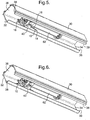
- Figures 3 and 4 show a cord spool support, generally 40 which can be used with the spring 10 in the head rail 30.
- the top 42 of the support 40 adjacent a lateral side 44, has a downwardly- and longitudinally-extending groove 46.
- the spring's horizontally-extending base portion 12 is seated in the groove 46 of the support 40.
- the depth of the groove 46 is only slightly greater than the diameter of the base portion 12 of the spring 10. It is also preferred that the spring's base portion 12 can slide vertically in the support's groove 46.
- the cord spool support 40 can be slid through the open longitudinal ends 32, 34 of the head rail 30 to fit snugly within the head rail with the top and bottom 42, 48 of the support closely adjacent to the horizontal, top and bottom, interior surfaces 36, 38, respectively, of the head rail.
- the groove 46 of the support can hold the horizontally-extending base portion 12 of the spring 10 with its vertically-extending arm portions 14 and acutely-angled arm portions 16 extending downwardly and its ends 18 in contact with, and bearing forcibly against, the bottom interior surface 38 of the head rail.
- the inwardly-bent curved portions 20 of the spring are adjacent to longitudinally-opposite sides 50, 52 of the support 40.
- the inwardly-bent curved portions 20 of the spring's vertically-extending arm portions 14 preferably are separated longitudinally by a distance equal to the longitudinal distance between the opposite sides 50, 52 of the support 40. Thereby, the inwardly-bent curved portions 20 of the spring 10 can hold the support 40 against longitudinal movement between the spring's vertically-extending arm portions 14 within the head rail 30.
- the height of the spring 10, when relaxed, is significantly greater than the height of the cord spool support 40 and the interior of the head rail 30.
- the vertical height of the spring is at least 6-15% greater than the vertical height of the interior of the head rail.
- the sharp circular edges of the ends 18 of the spring's acutely-angled arm portions 16 will grip tightly the head rail's bottom interior surface 38 to prevent the cord spool support 40 from moving significantly in a longitudinal direction within the head rail but will allow some adjustment of the longitudinal position of the support relative to an adjacent longitudinal end 60 of a cord spool 62.
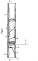
- Figure 7 shows the use of the cord spool support 40, holding the spring 10 of the invention, in the head rail 30 of a Roman shade.
- the support 40 holds, in a conventional manner, a longitudinal end 60 of a longitudinally-extending cord spool 62, so that the spool can be rotated by a user-operated, longitudinally-elongated rotatable rod (not shown), extending axially through the spool.
- Rotation of the spool 62 can be used to wind up and unwind a vertically-extending lift cord 64 that is attached to the spool and extends downwardly from the spool through a longitudinally-extending opening 39 in the bottom of the head rail.
- the head rail 30 of an actual Roman shade would typically have at lest two lift cords (not shown in Figure 7 ), each being attached to its own cord spool 62.
- a longitudinal end 60 of each spool 62 would be supported by a support 40, holding its own spring 10.
- Each lift cord 64 would extend downwardly from its spool 62 through the opening 39 in the bottom of the head rail.
Landscapes
- Engineering & Computer Science (AREA)
- Structural Engineering (AREA)
- Architecture (AREA)
- Civil Engineering (AREA)
- Curtains And Furnishings For Windows Or Doors (AREA)
- Window Of Vehicle (AREA)
- Blinds (AREA)
Claims (12)
- Verfahren zum Befestigen eines Schnurspulenträgers (40) in einer in Längsrichtung länglichen Kopfschiene (30) einer Fensterabdeckung, sodass der Träger (40) ein Ende einer sich in Längsrichtung erstreckenden Schnurspule (62) anliegend an einer sich in Längsrichtung erstreckenden Öffnung in der Schiene (30) hält, das Verfahren beinhaltend:Bereitstellen des Trägers (40) mit einer sich in Längs- und Vertikalrichtung erstreckenden Nut (46) in einer oberen Fläche an einer lateralen Seite; und Setzen in die Nut (46) eines sich horizontal erstreckenden Basisabschnitts (12) einer generell planaren, U-förmigen Metalldrahtfeder (10), mit zwei sich generell vertikal erstreckenden Armabschnitten (14), die an dem Basisabschnitt (12) angebracht sind, und zwei spitzwinklige Armabschnitte (16), die an den sich vertikal erstreckenden Armabschnitten (14) angebracht sind, aufweist;wobei sich die spitzwinkligen Armabschnitte (16) weg von dem Basisabschnitt (12) erstrecken und in Enden (18) mit scharfen Kanten enden; undwobei die vertikale Höhe der Feder (10), wenn sie entspannt ist, größer ist als die vertikale Höhe des Trägers (40) und der Innenseite der Schiene (30), sodass die scharfen Kanten ihrer zwei spitzwinkligen Armabschnitte (16) gegen eine horizontale Innenfläche der Schiene (30) vorgespannt sind und mit dieser in Reibungseingriff sind;wobei die Fensterabdeckung ein Raffrollo ist; unddie horizontale Innenfläche der Kopfschiene (30), die von den Enden (18) der Feder (10) mit scharfen Kanten eingegriffen ist, ihre untere Innenfläche ist und die sich vertikal erstreckenden Abschnitte (14) und die spitzwinkligen Abschnitte (16) der Feder (10) sich von dem sich horizontal erstreckenden Abschnitt der Feder (10) abwärts erstrecken.
- Verfahren nach Anspruch 1, wobei die zwei sich generell vertikal erstreckenden Armabschnitte (14) eng an den in Längsrichtung gegenüberliegenden Seiten (50, 52) des Trägers (40) anliegen.
- Verfahren nach Anspruch 1 oder 2, wobei der Basisabschnitt (12) der Feder (10) vertikal in der Nut (46) des Trägers (40) verschiebbar ist, sodass der Basisabschnitt (12) gegen eine horizontale obere Innenfläche (36) der Schiene (30) vorgespannt ist und mit dieser in Reibungseingriff ist.
- Verfahren nach den Ansprüchen 1, 2 oder 3, wobei die Feder (10) ein Federstahl ist und ihre Enden in scharfen kreisförmigen Kanten enden.
- Verfahren nach einem der Ansprüche 1 bis 4, wobei die vertikale Höhe der Feder (10) mindestens 6-15 % größer ist als die Höhe der Innenseite der Kopfschiene (30).
- Verfahren nach einem der Ansprüche 1-5, wobei es zwei oder mehr Schnurspulenträger (40) gibt, die jeweils ein Längsende (60) einer von einer Vielzahl von sich in Längsrichtung erstreckenden Schnurspulen (62) anliegend an der Öffnung in der Schiene halten; wobei jeder Träger (40) eine sich in Längs- und Vertikalrichtung erstreckende Nut (46) in einer oberen Fläche auf einer lateralen Seite aufweist und in jeder Nut (46) ein sich horizontal erstreckender Basisabschnitt (12) einer generell planaren, U-förmigen Metalldrahtfeder (10) sitzt, die zwei sich generell vertikal erstreckende Armabschnitte (14) aufweist, die an dem Basisabschnitt (12) angebracht sind, und zwei spitzwinklige Armabschnitte (16), die an den vertikal erstreckenden Armabschnitten (14) angebracht sind, sich weg von dem Basisabschnitt (12) erstrecken und in Enden (18) mit scharfen Kanten enden.
- Raffrollo, der folgendes aufweist:eine in Längsrichtung längliche Kopfschiene (30);ein Schnurspulenträger (40) zum Halten eines Endes einer sich in Längsrichtung erstreckenden Schnurspule (62) anliegend an einer sich in Längsrichtung erstreckenden Öffnung in der Schiene, wobei der Träger (40) mit einer sich in Längs- und Vertikalrichtung erstreckenden Nut (46) in einer oberen Fläche auf einer lateralen Seite versehen ist; undsitzend in der Nut (46), einen sich horizontal erstreckenden Basisabschnitt (12) einer generell planaren, U-förmigen Metalldrahtfeder (10), mit zwei sich generell vertikal erstreckenden Armabschnitten (14), die an dem Basisabschnitt (12) angebracht sind, und zwei spitzwinklige Armabschnitte (16), die an den sich vertikal erstreckenden Armabschnitten (14) angebracht sind;wobei sich die spitzwinkligen Armabschnitte (16) weg von dem Basisabschnitt (12) erstrecken und in Enden (18) mit scharfen Kanten enden; undwobei die vertikale Höhe der Feder (10), wenn sie entspannt ist, größer ist als die vertikale Höhe des Trägers (40) und der Schiene (30), sodass die scharfen Kanten ihrer zwei spitzwinkligen Armabschnitte (16) gegen eine horizontale Innenfläche der Schiene (30) vorgespannt sind und mit dieser in Reibungseingriff sind; wobei die horizontale Innenfläche der Kopfschiene (30), die von den Enden (18) der Feder (10) mit scharfen Kanten eingegriffen ist, ihre untere Innenfläche ist und die sich vertikal erstreckenden Abschnitte (14) und die spitzwinkligen Abschnitte (16) der Feder (10) sich von dem sich horizontal erstreckenden Abschnitt der Feder (10) abwärts erstrecken.
- Raffrollo nach Anspruch 7, wobei die zwei sich generell vertikal erstreckenden Armabschnitte (14) eng an den in Längsrichtung gegenüberliegenden Seiten (50, 52) des Trägers (40) anliegen.
- Raffrollo nach Anspruch 7 oder 8, wobei der Basisabschnitt (12) der Feder (10) vertikal in der Nut (46) des Trägers (40) verschiebbar ist, sodass der Basisabschnitt (12) gegen eine horizontale obere Innenfläche (36) der Schiene (30) vorgespannt ist und mit dieser in Reibungseingriff ist.
- Raffrollo nach den Ansprüchen 7, 8 oder 9, wobei die Feder (10) ein Federstahl ist und ihre Enden in scharfen kreisförmigen Kanten enden.
- Raffrollo nach einem der Ansprüche 7 bis 10, wobei die vertikale Höhe der Feder (10) mindestens 6-15 % größer ist als die Höhe der Innenseite der Kopfschiene (30).
- Raffrollo nach einem der Ansprüche 7 bis 11, wobei es zwei oder mehr Schnurspulenträger (40) gibt, die jeweils ein Längsende (60) einer von einer Vielzahl von sich in Längsrichtung erstreckenden Schnurspulen (62) anliegend an der Öffnung in der Schiene halten; wobei jeder Träger (40) eine sich in Längs- und Vertikalrichtung erstreckende Nut (46) in einer oberen Fläche auf einer lateralen Seite aufweist und in jeder Nut (46) ein sich horizontal erstreckender Basisabschnitt (12) einer generell planaren, U-förmigen Metalldrahtfeder (10) sitzt, die zwei sich generell vertikal erstreckende Armabschnitte (14) aufweist, die an dem Basisabschnitt (12) angebracht sind, und zwei spitzwinklige Armabschnitte (16), die an den vertikal erstreckenden Armabschnitten (14) angebracht sind, sich weg von dem Basisabschnitt (12) erstrecken und in Enden (18) mit scharfen Kanten enden.
Priority Applications (1)
| Application Number | Priority Date | Filing Date | Title |
|---|---|---|---|
| EP10252067.3A EP2336478B1 (de) | 2009-12-15 | 2010-12-07 | Fixierung einer Seilspulenhalterung |
Applications Claiming Priority (2)
| Application Number | Priority Date | Filing Date | Title |
|---|---|---|---|
| EP09015471 | 2009-12-15 | ||
| EP10252067.3A EP2336478B1 (de) | 2009-12-15 | 2010-12-07 | Fixierung einer Seilspulenhalterung |
Publications (3)
| Publication Number | Publication Date |
|---|---|
| EP2336478A2 EP2336478A2 (de) | 2011-06-22 |
| EP2336478A3 EP2336478A3 (de) | 2015-06-10 |
| EP2336478B1 true EP2336478B1 (de) | 2020-05-13 |
Family
ID=43830225
Family Applications (1)
| Application Number | Title | Priority Date | Filing Date |
|---|---|---|---|
| EP10252067.3A Active EP2336478B1 (de) | 2009-12-15 | 2010-12-07 | Fixierung einer Seilspulenhalterung |
Country Status (1)
| Country | Link |
|---|---|
| EP (1) | EP2336478B1 (de) |
Family Cites Families (3)
| Publication number | Priority date | Publication date | Assignee | Title |
|---|---|---|---|---|
| CH388127A (de) * | 1960-01-21 | 1965-02-15 | Hunter Douglas International C | Aufzugsvorrichtung einer Jalousie |
| US5996667A (en) | 1999-02-12 | 1999-12-07 | Fun; Fu-Mei | Window blind |
| US20070056692A1 (en) * | 2005-09-14 | 2007-03-15 | Nien Made Enterprise Co., Ltd. | Angle adjusting device for blind slats |
-
2010
- 2010-12-07 EP EP10252067.3A patent/EP2336478B1/de active Active
Non-Patent Citations (1)
| Title |
|---|
| None * |
Also Published As
| Publication number | Publication date |
|---|---|
| EP2336478A3 (de) | 2015-06-10 |
| EP2336478A2 (de) | 2011-06-22 |
Similar Documents
| Publication | Publication Date | Title |
|---|---|---|
| US7673665B2 (en) | Cordless flexible window covering | |
| US7059377B2 (en) | Double-layer roller blind | |
| EP2131008B1 (de) | Fensterabdeckung | |
| EP1594385B1 (de) | Lichtschutzvorrichtung mit pull-down/push-up-mechanismus | |
| US9765565B2 (en) | Cordless shade automatic lift regulator | |
| EP2031176A2 (de) | Verankerungsvorrichtung | |
| AU2004202671A1 (en) | Roller Level Adjustment Device for Roller Blind | |
| US20150034262A1 (en) | Covering for an architectural opening | |
| CA2919685A1 (en) | Brake device for cordless lift shades | |
| KR20170020240A (ko) | 창문 덮개를 위한 경사 조절 기구 | |
| AU2004203386A1 (en) | Fabric Window Blind | |
| US20180223594A1 (en) | Blind assembly and method of attaching a shade material to a winding core of a blind | |
| AU2010201939B2 (en) | Window coverings | |
| EP2336478B1 (de) | Fixierung einer Seilspulenhalterung | |
| EP1669537A2 (de) | Führungseinrichtung für aufrollbare Stores | |
| KR20120100472A (ko) | 스토퍼를 구비한 롤 스크린 | |
| EP2867433B1 (de) | Verriegelungselement für eine vorhangschiene, verfahren dafür und anordnung damit | |
| EP2020479A2 (de) | Rollblende für ein Dachfenster | |
| JP2014205992A (ja) | 日射遮蔽装置 | |
| US20200080368A1 (en) | Cordless blinds and shades lifter rods | |
| JP2002054374A (ja) | 日射遮蔽装置のボトムレール下限位置調整装置 | |
| JP4909799B2 (ja) | バランスブラケット | |
| JP2010112060A (ja) | ボトムレールの下限位置決め機構 | |
| JP3589953B2 (ja) | 横型ブラインドのボトムレール下限位置調整装置 | |
| KR200401026Y1 (ko) | 버티컬 블라인드의 조정줄 가이드 웨이트 |
Legal Events
| Date | Code | Title | Description |
|---|---|---|---|
| PUAI | Public reference made under article 153(3) epc to a published international application that has entered the european phase |
Free format text: ORIGINAL CODE: 0009012 |
|
| AK | Designated contracting states |
Kind code of ref document: A2 Designated state(s): AL AT BE BG CH CY CZ DE DK EE ES FI FR GB GR HR HU IE IS IT LI LT LU LV MC MK MT NL NO PL PT RO RS SE SI SK SM TR |
|
| PUAL | Search report despatched |
Free format text: ORIGINAL CODE: 0009013 |
|
| AK | Designated contracting states |
Kind code of ref document: A3 Designated state(s): AL AT BE BG CH CY CZ DE DK EE ES FI FR GB GR HR HU IE IS IT LI LT LU LV MC MK MT NL NO PL PT RO RS SE SI SK SM TR |
|
| RIC1 | Information provided on ipc code assigned before grant |
Ipc: E06B 9/323 20060101ALI20150504BHEP Ipc: E06B 9/322 20060101AFI20150504BHEP |
|
| 17P | Request for examination filed |
Effective date: 20151209 |
|
| RBV | Designated contracting states (corrected) |
Designated state(s): AL AT BE BG CH CY CZ DE DK EE ES FI FR GB GR HR HU IE IS IT LI LT LU LV MC MK MT NL NO PL PT RO RS SE SI SK SM TR |
|
| STAA | Information on the status of an ep patent application or granted ep patent |
Free format text: STATUS: EXAMINATION IS IN PROGRESS |
|
| 17Q | First examination report despatched |
Effective date: 20171218 |
|
| GRAP | Despatch of communication of intention to grant a patent |
Free format text: ORIGINAL CODE: EPIDOSNIGR1 |
|
| STAA | Information on the status of an ep patent application or granted ep patent |
Free format text: STATUS: GRANT OF PATENT IS INTENDED |
|
| INTG | Intention to grant announced |
Effective date: 20191211 |
|
| GRAS | Grant fee paid |
Free format text: ORIGINAL CODE: EPIDOSNIGR3 |
|
| GRAA | (expected) grant |
Free format text: ORIGINAL CODE: 0009210 |
|
| STAA | Information on the status of an ep patent application or granted ep patent |
Free format text: STATUS: THE PATENT HAS BEEN GRANTED |
|
| AK | Designated contracting states |
Kind code of ref document: B1 Designated state(s): AL AT BE BG CH CY CZ DE DK EE ES FI FR GB GR HR HU IE IS IT LI LT LU LV MC MK MT NL NO PL PT RO RS SE SI SK SM TR |
|
| REG | Reference to a national code |
Ref country code: GB Ref legal event code: FG4D |
|
| REG | Reference to a national code |
Ref country code: CH Ref legal event code: EP |
|
| REG | Reference to a national code |
Ref country code: DE Ref legal event code: R096 Ref document number: 602010064323 Country of ref document: DE |
|
| REG | Reference to a national code |
Ref country code: AT Ref legal event code: REF Ref document number: 1270505 Country of ref document: AT Kind code of ref document: T Effective date: 20200615 |
|
| REG | Reference to a national code |
Ref country code: NL Ref legal event code: FP |
|
| REG | Reference to a national code |
Ref country code: LT Ref legal event code: MG4D |
|
| PG25 | Lapsed in a contracting state [announced via postgrant information from national office to epo] |
Ref country code: NO Free format text: LAPSE BECAUSE OF FAILURE TO SUBMIT A TRANSLATION OF THE DESCRIPTION OR TO PAY THE FEE WITHIN THE PRESCRIBED TIME-LIMIT Effective date: 20200813 Ref country code: GR Free format text: LAPSE BECAUSE OF FAILURE TO SUBMIT A TRANSLATION OF THE DESCRIPTION OR TO PAY THE FEE WITHIN THE PRESCRIBED TIME-LIMIT Effective date: 20200814 Ref country code: SE Free format text: LAPSE BECAUSE OF FAILURE TO SUBMIT A TRANSLATION OF THE DESCRIPTION OR TO PAY THE FEE WITHIN THE PRESCRIBED TIME-LIMIT Effective date: 20200513 Ref country code: LT Free format text: LAPSE BECAUSE OF FAILURE TO SUBMIT A TRANSLATION OF THE DESCRIPTION OR TO PAY THE FEE WITHIN THE PRESCRIBED TIME-LIMIT Effective date: 20200513 Ref country code: PT Free format text: LAPSE BECAUSE OF FAILURE TO SUBMIT A TRANSLATION OF THE DESCRIPTION OR TO PAY THE FEE WITHIN THE PRESCRIBED TIME-LIMIT Effective date: 20200914 Ref country code: FI Free format text: LAPSE BECAUSE OF FAILURE TO SUBMIT A TRANSLATION OF THE DESCRIPTION OR TO PAY THE FEE WITHIN THE PRESCRIBED TIME-LIMIT Effective date: 20200513 Ref country code: IS Free format text: LAPSE BECAUSE OF FAILURE TO SUBMIT A TRANSLATION OF THE DESCRIPTION OR TO PAY THE FEE WITHIN THE PRESCRIBED TIME-LIMIT Effective date: 20200913 |
|
| PG25 | Lapsed in a contracting state [announced via postgrant information from national office to epo] |
Ref country code: LV Free format text: LAPSE BECAUSE OF FAILURE TO SUBMIT A TRANSLATION OF THE DESCRIPTION OR TO PAY THE FEE WITHIN THE PRESCRIBED TIME-LIMIT Effective date: 20200513 Ref country code: HR Free format text: LAPSE BECAUSE OF FAILURE TO SUBMIT A TRANSLATION OF THE DESCRIPTION OR TO PAY THE FEE WITHIN THE PRESCRIBED TIME-LIMIT Effective date: 20200513 Ref country code: RS Free format text: LAPSE BECAUSE OF FAILURE TO SUBMIT A TRANSLATION OF THE DESCRIPTION OR TO PAY THE FEE WITHIN THE PRESCRIBED TIME-LIMIT Effective date: 20200513 Ref country code: BG Free format text: LAPSE BECAUSE OF FAILURE TO SUBMIT A TRANSLATION OF THE DESCRIPTION OR TO PAY THE FEE WITHIN THE PRESCRIBED TIME-LIMIT Effective date: 20200813 |
|
| REG | Reference to a national code |
Ref country code: AT Ref legal event code: MK05 Ref document number: 1270505 Country of ref document: AT Kind code of ref document: T Effective date: 20200513 |
|
| PG25 | Lapsed in a contracting state [announced via postgrant information from national office to epo] |
Ref country code: AL Free format text: LAPSE BECAUSE OF FAILURE TO SUBMIT A TRANSLATION OF THE DESCRIPTION OR TO PAY THE FEE WITHIN THE PRESCRIBED TIME-LIMIT Effective date: 20200513 |
|
| PG25 | Lapsed in a contracting state [announced via postgrant information from national office to epo] |
Ref country code: ES Free format text: LAPSE BECAUSE OF FAILURE TO SUBMIT A TRANSLATION OF THE DESCRIPTION OR TO PAY THE FEE WITHIN THE PRESCRIBED TIME-LIMIT Effective date: 20200513 Ref country code: RO Free format text: LAPSE BECAUSE OF FAILURE TO SUBMIT A TRANSLATION OF THE DESCRIPTION OR TO PAY THE FEE WITHIN THE PRESCRIBED TIME-LIMIT Effective date: 20200513 Ref country code: CZ Free format text: LAPSE BECAUSE OF FAILURE TO SUBMIT A TRANSLATION OF THE DESCRIPTION OR TO PAY THE FEE WITHIN THE PRESCRIBED TIME-LIMIT Effective date: 20200513 Ref country code: DK Free format text: LAPSE BECAUSE OF FAILURE TO SUBMIT A TRANSLATION OF THE DESCRIPTION OR TO PAY THE FEE WITHIN THE PRESCRIBED TIME-LIMIT Effective date: 20200513 Ref country code: IT Free format text: LAPSE BECAUSE OF FAILURE TO SUBMIT A TRANSLATION OF THE DESCRIPTION OR TO PAY THE FEE WITHIN THE PRESCRIBED TIME-LIMIT Effective date: 20200513 Ref country code: SM Free format text: LAPSE BECAUSE OF FAILURE TO SUBMIT A TRANSLATION OF THE DESCRIPTION OR TO PAY THE FEE WITHIN THE PRESCRIBED TIME-LIMIT Effective date: 20200513 Ref country code: AT Free format text: LAPSE BECAUSE OF FAILURE TO SUBMIT A TRANSLATION OF THE DESCRIPTION OR TO PAY THE FEE WITHIN THE PRESCRIBED TIME-LIMIT Effective date: 20200513 Ref country code: EE Free format text: LAPSE BECAUSE OF FAILURE TO SUBMIT A TRANSLATION OF THE DESCRIPTION OR TO PAY THE FEE WITHIN THE PRESCRIBED TIME-LIMIT Effective date: 20200513 |
|
| REG | Reference to a national code |
Ref country code: DE Ref legal event code: R097 Ref document number: 602010064323 Country of ref document: DE |
|
| PG25 | Lapsed in a contracting state [announced via postgrant information from national office to epo] |
Ref country code: SK Free format text: LAPSE BECAUSE OF FAILURE TO SUBMIT A TRANSLATION OF THE DESCRIPTION OR TO PAY THE FEE WITHIN THE PRESCRIBED TIME-LIMIT Effective date: 20200513 Ref country code: PL Free format text: LAPSE BECAUSE OF FAILURE TO SUBMIT A TRANSLATION OF THE DESCRIPTION OR TO PAY THE FEE WITHIN THE PRESCRIBED TIME-LIMIT Effective date: 20200513 |
|
| PLBE | No opposition filed within time limit |
Free format text: ORIGINAL CODE: 0009261 |
|
| STAA | Information on the status of an ep patent application or granted ep patent |
Free format text: STATUS: NO OPPOSITION FILED WITHIN TIME LIMIT |
|
| 26N | No opposition filed |
Effective date: 20210216 |
|
| PG25 | Lapsed in a contracting state [announced via postgrant information from national office to epo] |
Ref country code: SI Free format text: LAPSE BECAUSE OF FAILURE TO SUBMIT A TRANSLATION OF THE DESCRIPTION OR TO PAY THE FEE WITHIN THE PRESCRIBED TIME-LIMIT Effective date: 20200513 |
|
| REG | Reference to a national code |
Ref country code: DE Ref legal event code: R119 Ref document number: 602010064323 Country of ref document: DE |
|
| REG | Reference to a national code |
Ref country code: CH Ref legal event code: PL |
|
| GBPC | Gb: european patent ceased through non-payment of renewal fee |
Effective date: 20201207 |
|
| PG25 | Lapsed in a contracting state [announced via postgrant information from national office to epo] |
Ref country code: MC Free format text: LAPSE BECAUSE OF FAILURE TO SUBMIT A TRANSLATION OF THE DESCRIPTION OR TO PAY THE FEE WITHIN THE PRESCRIBED TIME-LIMIT Effective date: 20200513 |
|
| REG | Reference to a national code |
Ref country code: BE Ref legal event code: MM Effective date: 20201231 |
|
| PG25 | Lapsed in a contracting state [announced via postgrant information from national office to epo] |
Ref country code: IE Free format text: LAPSE BECAUSE OF NON-PAYMENT OF DUE FEES Effective date: 20201207 Ref country code: FR Free format text: LAPSE BECAUSE OF NON-PAYMENT OF DUE FEES Effective date: 20201231 Ref country code: LU Free format text: LAPSE BECAUSE OF NON-PAYMENT OF DUE FEES Effective date: 20201207 |
|
| PG25 | Lapsed in a contracting state [announced via postgrant information from national office to epo] |
Ref country code: DE Free format text: LAPSE BECAUSE OF NON-PAYMENT OF DUE FEES Effective date: 20210701 Ref country code: GB Free format text: LAPSE BECAUSE OF NON-PAYMENT OF DUE FEES Effective date: 20201207 Ref country code: CH Free format text: LAPSE BECAUSE OF NON-PAYMENT OF DUE FEES Effective date: 20201231 Ref country code: LI Free format text: LAPSE BECAUSE OF NON-PAYMENT OF DUE FEES Effective date: 20201231 |
|
| PG25 | Lapsed in a contracting state [announced via postgrant information from national office to epo] |
Ref country code: TR Free format text: LAPSE BECAUSE OF FAILURE TO SUBMIT A TRANSLATION OF THE DESCRIPTION OR TO PAY THE FEE WITHIN THE PRESCRIBED TIME-LIMIT Effective date: 20200513 Ref country code: MT Free format text: LAPSE BECAUSE OF FAILURE TO SUBMIT A TRANSLATION OF THE DESCRIPTION OR TO PAY THE FEE WITHIN THE PRESCRIBED TIME-LIMIT Effective date: 20200513 Ref country code: CY Free format text: LAPSE BECAUSE OF FAILURE TO SUBMIT A TRANSLATION OF THE DESCRIPTION OR TO PAY THE FEE WITHIN THE PRESCRIBED TIME-LIMIT Effective date: 20200513 |
|
| PG25 | Lapsed in a contracting state [announced via postgrant information from national office to epo] |
Ref country code: MK Free format text: LAPSE BECAUSE OF FAILURE TO SUBMIT A TRANSLATION OF THE DESCRIPTION OR TO PAY THE FEE WITHIN THE PRESCRIBED TIME-LIMIT Effective date: 20200513 |
|
| PG25 | Lapsed in a contracting state [announced via postgrant information from national office to epo] |
Ref country code: BE Free format text: LAPSE BECAUSE OF NON-PAYMENT OF DUE FEES Effective date: 20201231 |
|
| P01 | Opt-out of the competence of the unified patent court (upc) registered |
Effective date: 20230331 |
|
| PGFP | Annual fee paid to national office [announced via postgrant information from national office to epo] |
Ref country code: NL Payment date: 20241024 Year of fee payment: 15 |
|
| PG25 | Lapsed in a contracting state [announced via postgrant information from national office to epo] |
Ref country code: IS Free format text: LAPSE BECAUSE OF NON-PAYMENT OF DUE FEES Effective date: 20200913 |