EP2336002A1 - Electric power steering device - Google Patents
Electric power steering device Download PDFInfo
- Publication number
- EP2336002A1 EP2336002A1 EP09813025A EP09813025A EP2336002A1 EP 2336002 A1 EP2336002 A1 EP 2336002A1 EP 09813025 A EP09813025 A EP 09813025A EP 09813025 A EP09813025 A EP 09813025A EP 2336002 A1 EP2336002 A1 EP 2336002A1
- Authority
- EP
- European Patent Office
- Prior art keywords
- target
- current
- torque
- motor
- map
- Prior art date
- Legal status (The legal status is an assumption and is not a legal conclusion. Google has not performed a legal analysis and makes no representation as to the accuracy of the status listed.)
- Granted
Links
Images



Classifications
-
- B—PERFORMING OPERATIONS; TRANSPORTING
- B62—LAND VEHICLES FOR TRAVELLING OTHERWISE THAN ON RAILS
- B62D—MOTOR VEHICLES; TRAILERS
- B62D5/00—Power-assisted or power-driven steering
- B62D5/04—Power-assisted or power-driven steering electrical, e.g. using an electric servo-motor connected to, or forming part of, the steering gear
- B62D5/0457—Power-assisted or power-driven steering electrical, e.g. using an electric servo-motor connected to, or forming part of, the steering gear characterised by control features of the drive means as such
- B62D5/046—Controlling the motor
-
- H—ELECTRICITY
- H02—GENERATION; CONVERSION OR DISTRIBUTION OF ELECTRIC POWER
- H02P—CONTROL OR REGULATION OF ELECTRIC MOTORS, ELECTRIC GENERATORS OR DYNAMO-ELECTRIC CONVERTERS; CONTROLLING TRANSFORMERS, REACTORS OR CHOKE COILS
- H02P21/00—Arrangements or methods for the control of electric machines by vector control, e.g. by control of field orientation
- H02P21/0085—Arrangements or methods for the control of electric machines by vector control, e.g. by control of field orientation specially adapted for high speeds, e.g. above nominal speed
- H02P21/0089—Arrangements or methods for the control of electric machines by vector control, e.g. by control of field orientation specially adapted for high speeds, e.g. above nominal speed using field weakening
-
- H—ELECTRICITY
- H02—GENERATION; CONVERSION OR DISTRIBUTION OF ELECTRIC POWER
- H02P—CONTROL OR REGULATION OF ELECTRIC MOTORS, ELECTRIC GENERATORS OR DYNAMO-ELECTRIC CONVERTERS; CONTROLLING TRANSFORMERS, REACTORS OR CHOKE COILS
- H02P21/00—Arrangements or methods for the control of electric machines by vector control, e.g. by control of field orientation
- H02P21/06—Rotor flux based control involving the use of rotor position or rotor speed sensors
-
- H—ELECTRICITY
- H02—GENERATION; CONVERSION OR DISTRIBUTION OF ELECTRIC POWER
- H02P—CONTROL OR REGULATION OF ELECTRIC MOTORS, ELECTRIC GENERATORS OR DYNAMO-ELECTRIC CONVERTERS; CONTROLLING TRANSFORMERS, REACTORS OR CHOKE COILS
- H02P25/00—Arrangements or methods for the control of AC motors characterised by the kind of AC motor or by structural details
- H02P25/02—Arrangements or methods for the control of AC motors characterised by the kind of AC motor or by structural details characterised by the kind of motor
- H02P25/022—Synchronous motors
- H02P25/024—Synchronous motors controlled by supply frequency
Definitions
- the present invention relates to a electric power steering device which controls a motor torque on the basis of a steering-torque signal and a speed signal in order to assist a steering, and more particularly, relates to the electric power steering device which assists a steering with a synchronous reluctance motor.
- a electric power steering device is a steering-force supporting device to reduce a steering force generated by a steering operation by a driver by causing an electric motor (a motor) to generate an auxiliary torque in accordance with the largeness of a steering torque of a vehicle and to transmit the auxiliary torque to a steering system.
- a motor used in the electric power steering device is a synchronous reluctance motor.
- the synchronous reluctance motor makes a rotary operation by a reluctance torque generated at a steel-plate layer of a rotator having no magnet, and in general, has a structure in which a stator has a three-phase windings, and the rotator has grooves of air (air layers) that are referred to as flux barriers provided inside the steel-plate layer.
- a stator has a three-phase windings
- the rotator has grooves of air (air layers) that are referred to as flux barriers provided inside the steel-plate layer.
- Such a structure enables the synchronous reluctance motor to generate a rotating torque (hereinafter, simply referred to as a torque) without needing an expensive rare-earth magnet or the like, resulting in a cost reduction, and good recyclability.
- the synchronous reluctance motor has a nonlinear torque-current characteristic and calculates a target current and a current advance angle (the advancing phase angle of an armature current relative to an induced voltage) using a target torque and a motor revolutionary speed.
- an advance-angle correction value is obtained with the absolute value of the target torque being divided into three points (i.e., a region (T ⁇ T1) where the absolute value of the target torque (T) is smaller than a target torque (T1) at the maximum revolutionary speed, a region (T1 ⁇ T ⁇ T3) where the absolute value of the target torque (T) is present between the foregoing target torque and a target torque (T3) that is a midpoint between a nonlinear curve of the torque-current characteristic and a linear curve thereof, and a region (T3 ⁇ T) where the absolute value of the target value (T) is larger than T3), and is calculated for each revolutionary speed.
- the calculated target current is output in a current form of a three-phase current or a d-axis current/q-axis current.
- a technology that controls a torque of the synchronous reluctance motor through such a method is disclosed in, for example, patent literature 1 and patent literature 2.
- the technology disclosed in these patent literatures intends to perform torque control from a low-output torque to a high-output torque by detecting the position of the rotator and the speed thereof in order to obtain a torque instruction even though the torque-current characteristic of the synchronous reluctance motor is nonlinear.
- an advance-angle correction value (AX) is calculated with the absolute value of a difference between a maximum revolutionary speed (N3) and a present revolutionary speed (N) being as a part of an input.
- the present invention is made in view of these problems, and it is an object of the present invention to provide a electric power steering device that can perform good torque control through a simple arithmetic process using a synchronous reluctance motor having a nonlinear torque-current characteristic.
- a first aspect of the present invention provides a electric power steering device employing a configuration in which the electric power steering device drives a synchronous reluctance motor based on a signal from a steering input detecting unit and assists a steering, in which the electric power steering device comprises: a target-torque calculating unit that calculates a target torque output by the synchronous reluctance motor based on at least a steering input signal; and a target-current calculating unit that calculates a target current to the synchronous reluctance motor based on a signal from the target-torque calculating unit, in which the target-current calculating unit calculates a motor-current effective value and a motor-current phase which are necessary for generating a target torque value and the synchronous reluctance motor is driven by calculating a d-axis current and a q-axis current based on the motor-current effective value and the motor-current phase.
- a motor-current effective value (a target-current effective value) I and a motor-current phase (a target-current phase) ⁇ are calculated from a target torque, and a d-axis current and a q-axis current are calculated based on the target-current effective value I and the target-current phase ⁇ in order to drive/control the synchronous reluctance motor. Accordingly, good torque control is enabled even though the synchronous reluctance motor has a nonlinear torque-current characteristic. In other words, when the synchronous reluctance motor is subjected to target torque control, it is possible to optimize a motor current in order to perform the torque control.
- a second aspect of the present invention provides the electric power steering device of the first aspect of the present invention, in which the target-current calculating unit includes a map for calculating the motor-current effective value and the motor-current phase ⁇ from the input target torque value, and the map includes at least two maps which are a normal range map and a high-output range map.
- the target-current calculating unit has the normal range map (a maximum torque map) and the high-output range map (a maximum output map), it is possible to uniquely obtain the target-current effective value I and the target-current phase ⁇ when the target torque is input to the target-current calculating unit.
- a third aspect of the present invention provides the electric power steering device of the second aspect of the present invention, in which the map is changed from the normal range map to the high-output range map when a duty ratio of driving power output to the synchronous reluctance motor is equal to or larger than a predetermined value.
- the duty ratio becomes equal to or larger than the predetermined value (e.g., when the duty ratio becomes equal to or larger than 80 %)
- the change of the map from the normal range map to the high-output range map is enabled.
- the duty ratio becomes equal to or less than the predetermined value (e.g., when the duty ratio becomes equal to or less than 70 % in consideration of hysteresis)
- it may be configured so that the map is changed from the high-output range map to the normal range map.
- FIG. 1 is an overall configuration diagram of a electric power steering device 1 including a synchronous reluctance motor according to an embodiment of the present invention.
- the electric power steering device 1 includes a steering wheel 2, and the steering wheel 2 is joined with a pinion shaft 4 through a steering shaft 3.
- a steering torque generated by the operation of the steering wheel 2 given by a driver is transmitted to the pinion shaft 4 through the steering shaft 3.
- the pinion shaft 4 is provided with a magneto strictive torque sensor 5 which detects the steering torque that acts on a steering system and a torque transmitting unit 6, and the torque transmitting unit 6 is coupled to an electric machinery (electric motor) 7 that applies an auxiliary torque to the steering system.
- the electric motor 7 a synchronous reluctance motor is used.
- the torque sensor 5 may be other torque detecting elements in other forms like an optical torque sensor in addition to a magnetostrictive sensor.
- the electric power steering device 1 employs a so-called rack-and-pinion configuration, a pinion 4A provided at the lower end of the pinion shaft 4 meshes with a rack tooth 8A formed around a rack shaft 8, and the rotation of the pinion shaft 4 is converted into a displacement in the axial direction of the rack shaft 8, so that wheels to be steered 9, 9 are steered.
- the torque sensor 5 outputs a steering-torque signal T to a control device 10.
- the control device 10 calculates an auxiliary torque on the basis of the steering-torque signal T output by the torque sensor 5 and a vehicle speed signal v output by a speed sensor 11 and controls the electric motor 7 by outputting a three-phase electric motor driving voltage V0 to the electric motor 7.
- the torque transmitting unit 6 is configured to rotate the pinion shaft 4 through a worm gear (not shown) with the rotating torque by the electric motor 7. It is configured that the auxiliary torque by the electric motor 7 is transmitted through the torque transmitting unit 6 to the pinion shaft 4, and is further transmitted to the steering system from the rack shaft 8 through the pinion 4A and the rack tooth 8A, and the wheel to be steered 9 is steered. Note that FIG. 1 shows the major part of the steering system.
- a rotative force generated based on the steering torque which is applied to the steering shaft 3 is converted into a straight motion of the rack shaft 8 in the axial direction from the pinion 4A through the rack tooth 8A, and causes the running direction of the steering wheels to be steered 9, 9 to be changed.
- the torque sensor 5 attached to the steering shaft 3 simultaneously detects the steering torque corresponding to the steering operation of the steering wheel 2 given by the driver, converts the detected torque to the electrical steering-torque signal T, and outputs the steering-torque signal T to the control device 10.
- the speed sensor 11 detects the vehicle speed signal v, and outputs such a signal to the control device 10.
- the control device 10 generates the electric motor driving voltage V0 for driving the electric motor 7 on the basis of a target signal based on the steering-torque signal T and the speed signal v and of an angular signal ⁇ indicating the rotation angle of the electric motor 7. At this time, the control device 10 performs dq-vector conversion which decomposes the electric motor driving voltage V0 to a d-axis (a magnetic flux axis) and a q-axis (a torque axis) that is electrically orthogonal to the d-axis at a right angle and which controls the electric motor driving voltage using an electric-motor current I0 and an angular signal ⁇ 0.
- the electric motor 7 is rotated and driven based on the three-phase electric motor driving voltage V0 of U, V, and W phases, and a three-phase alternating current IAC (Iu, Iv, and Iw) flows through.
- an auxiliary steering force based on the rotating torque of the electric motor 7 acts on the pinion shaft 4 joined with the steering shaft 3 through the torque transmitting unit 6, and is transmitted to the rack shaft 8 by the rack-and-pinion configuration.
- the steering force applied to the steering wheel 2 by the driver is reduced.
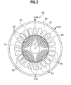
- FIG. 2 is a cross-sectional view of the general synchronous reluctance motor 35.
- the synchronous reluctance motor 35 is provided with a rotator 30 having four magnetic poles (a pair of binary poles) and a stator 20 having 24 slots 23.
- the stator 20 of the synchronous reluctance motor 35 is provided with a stator main body 21, and the plural slots 23 and T-shaped teeth 24 formed on an inner circumference surface 22 of the stator main body 21.
- the rotator 30 is provided with plural linear flux barriers (air layers) 32 each formed to a predetermined width and length relative to a rotator main body 31, and plural steel-plate ribs (ribs) 33 are formed. Both ends of each steel-plate rib (rib) 33 are provided at the outer circumference of the rotator 30.
- the rotator main body 31 is comprised of a magnetic material like an electromagnetic steel plate.
- the plural flux barriers 32 may be formed of a nonmagnetic material like a resin in addition to the form of the air layers.
- the plural flux barriers 32 are arranged radially around the q-axis (the torque axis) that is mechanically inclined at 45 degree with the d-axis (the magnetic flux axis) being as a border. Accordingly, four pairs of the flux barrier 32 and the steel-plate rib 33 arranged around the q-axis are radially provided. Also, the d-axis is orthogonal to a rotator axis, and is consistent with the axis of the steel-plate rib 33 at the both ends of the steel-plate rib 33.
- the synchronous reluctance motor 35 configured as explained above will be explained.
- a magnetic field is generated at the tooth 24, and a magnetic flux returns to another tooth 24 through the rotator 30.
- the plural flux barriers 32 are provided inside the rotator main body 31, there are a direction (the d-axis direction) through which the magnetic flux easily passes and a direction (the q-axis direction) through which the magnetic flux does not easily pass.
- the difference between a d-axis magnetic flux and a q-axis magnetic flux (a magnetic reluctance difference) generates a reluctance torque, so that the rotator 30 rotates in a predetermined direction.
- the flux barriers 32 and the steel-plate ribs 33 facing the teeth 24 have a little change in the magnetic flux even if the rotator 30 rotates, and does not become a cause of generating a torque ripple.
- the torque ripple is generated because of a mutual positional relationship between a minute slot aperture 23 a formed between the adjoining teeth 24 and the flux barrier 32 (or the steel-plate rib 33).
- the magnetic flux changes when the slot aperture 23a of the stator 20 faces the steel-plate rib 33 of the rotator 30 or when the slot aperture 23a of the stator 20 faces the flux barrier 32 of the rotator 30, so that the change in the mutual position between the stator 20 and the rotator 30 (i.e., by a rotation of the rotator 30) generates the torque ripple in the rotating torque by the rotator 30.
- a conventionally well-known technology that suppresses a generation of the torque ripple may be employed by changing the shape of the flux barriers 32.
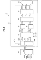
- FIG. 3 is a block diagram showing the configuration of the motor control system 40 of the electric power steering device 1 using the synchronous reluctance motor according to the embodiment of the present invention.
- the function of the motor control system 40 is realized by a computer having a CPU, a RAM, an I/O, and the like and a predetermined program installed in that computer.
- the motor control system 40 shown in FIG. 3 comprises an EPS (a motor-driven power steering) control unit 41 and a motor control unit 51.
- the EPS control unit 41 includes a target-torque calculating unit 42.
- the motor control unit 51 includes a target-current calculating unit 52, a three-phase biaxial converting unit 53, a q-axis (the torque axis) PI control unit 54, a d-axis (the magnetic flux axis) PI control unit 55, a biaxial three-phase converting unit 56, a PWM converting unit 57, and a motor (the synchronous reluctance motor) 58.
- the target-current calculating unit 52 includes a maximum torque map (a normal range map) 52a and a maximum output map (a high-output range map) 52b.
- the target-torque calculating unit 42 of the EPS control unit 41 receives inputting of a torque sensor signal, a vehicle speed, and the revolutionary speed of the motor (the synchronous reluctance motor) 58, calculates a target torque to be output by the motor 58, and outputs the target torque to the target-current calculating unit 52 of the motor control unit 51. That is, a target value transmitted from the EPS control unit 41 to the motor control unit 51 is the value of the target torque.
- the target-current calculating unit 52 in the motor control unit 51 calculates a target-current effective value I and a target-current phase ⁇ from the input target torque.
- the target-current effective value I and the target-current phase ⁇ are calculated in such a way that (a) the motor 58 can output a maximum torque T (a maximum torque obtainable at a minimum current effective value) or (b) the motor 58 can output a maximum output W (a maximum output obtainable at the minimum current effective value).
- N is the revolutionary speed of the motor 58.
- the target-current calculating unit 52 changes over the conditions in which (a) the maximum torque T is set as the target value or (b) the maximum output W is set as the target value in accordance with the level of the duty (DUTY) ratio of a signal (a driving current) output by the PWM converting unit 57 comprising a three-phase inverter as will be discussed later.
- the method of calculating a target current by the target-current calculating unit 52 is realized by calculating a target three-phase current or a target d-axis current/target q-axis current and by giving these currents back to a current feedback system so as to obtain a target torque. That is, because a motor control controls a current that flows through the motor 58, so that the target three-phase current or the target d-axis current/target q-axis current is calculated from the target torque in order to perform the motor control.
- the target-current calculating unit 52 has the maximum torque map (the normal range map) 52a and the maximum output map (the high-output range map) 52b, changes over these maps and uses any one of these maps, and calculates the target current from the target torque.
- Changing of the maximum torque map 52a for obtaining the target value of the maximum torque T and the maximum output map 52b for obtaining the target value of the maximum output W is performed on the basis of the level of the duty ratio output by the PWM converting unit 57 comprising a three-phase inverter.
- the map is changed to the maximum torque map 52a, and when that duty ratio is equal to or larger than the predetermined value, the map is changed to the maximum output map 52b.
- the target-current effective value I and the target-current phase ⁇ which are calculated by the target-current calculating unit 52 from the target torque are output to the three-phase biaxial converting unit 53.
- the three-phase biaxial converting unit 53 inputs the target-current effective value I and the target-current phase ⁇ and converts the three phase currents IU, IV, and IW to a biaxial current (a dq-axes current) including a current of d-axis (the target d-axis current Id) that is the magnetic flux axis (an excitation axis) of the rotator of the motor 58 and a current of q-axis (the target q-axis current Iq) that is an axis electrically rotated by 90 degrees from the d-axis.
- a biaxial current a dq-axes current
- a dq-axes current including a current of d-axis (the target d-axis current Id) that is the magnetic flux axis (an excitation axis) of the rotator of the motor 58 and a current of q-axis (the target q-axis current Iq) that is an axis electrical
- the value of the target q-axis current Iq is proportional to a generated torque TM of the motor 58, and the value of the target d-axis current Id is proportional to an excitation current.
- an angle advancement can be performed by changing the target d-axis current Id and the target q-axis current Iq as needed. That is, by controlling the target d-axis current Id and the target q-axis current Iq, a control corresponding to the field weakening control of a brushless motor is performed. In this fashion, a steering feeling is improved by controlling the target torque while achieving an effect corresponding to that of the field weakening control.
- the q-axis (the torque axis) PI control unit 54 to which the target q-axis current Iq is input generates a q-axis voltage Vq by performing P (proportion) control and I (integral) control so as to reduce a deviation signal, and outputs the q-axis voltage Vq to the biaxial three-phase converting unit 56.
- the d-axis (the magnetic flux axis) PI control unit 55 to which the target d-axis current Id is input generates a d-axis voltage Vd by performing the PI control so as to reduce output signals by an adder (not shown), and outputs the d-axis voltage Vd to the biaxial three-phase converting unit 56.
- the biaxial three-phase converting unit 56 converts a biaxial signal including an output signal Vq by the q-axis (the torque axis) PI control unit 54 and an output signal Vd by the d-axis (the magnetic flux axis) PI control unit 55 to three-phase signals VU, VV, and VW.
- the PWM converting unit 57 generates DUTY signals (DUTY U, DUTY V, and DUTY W) which are ON/OFF signals (PWM (Pulse Width Modulation) signals) having a pulse width that is proportional to the levels of respective input three-phase signals VU, VV, and VW, and outputs the generated signal to the motor 58.
- An angular signal ⁇ of the motor 58 is input to the biaxial three-phase converting unit 56 and the PWM converting unit 57, and signals are output at a timing in accordance with the position of the magnetic pole of the rotator 30 (see FIG. 2 ).
- the target-torque calculating unit 42 of the EPS control unit 41 calculates the target torque to be output by the motor (the synchronous reluctance motor) 58 on the basis of steering input signals (i.e., a torque sensor signal, a vehicle speed signal, and a motor revolutionary speed signal) input by an unillustrated steering input detecting unit, and outputs the target torque to the target-current calculating unit 52 of the motor control unit 51.
- the motor the synchronous reluctance motor
- the target-current calculating unit calculates a motor-current effective value (the target-current effective value) I and motor-current phase (the target-current phase) ⁇ which are necessary for generating the input target torque value, and outputs the target-current effective value I and the target-current phase ⁇ to the three-phase biaxial converting unit 53.
- the three-phase biaxial converting unit 53 calculates the target q-axis current Iq and the target d-axis current on the basis of the target-current effective value I and the target-current phase ⁇ , so that the PWM converting unit 57 performs PWM control to drive the motor (the synchronous reluctance motor) 58 on the basis of the target q-axis current Iq and the target d-axis current.
- the target-current calculating unit 52 of the motor control unit 51 has two maps for calculating the motor-current effective value (the target-current effective value) I and the motor-current phase (the target-current phase) ⁇ from the input target torque value. That is, the target-current calculating unit 52 has the maximum torque map 52a that is the normal range map and the maximum output map 52b that is the high-output range map.
- the map is changed from the normal range map (the maximum torque map 52a) to the high-output range map (the maximum output map 52b), and when the duty ratio becomes equal to or less than the predetermined value, the map is changed from the high-output range map (the maximum output map 52b) to the normal range map (the maximum torque map 52a).
- the map is changed from the normal range map (the maximum torque map 52a) to the high-output range map (the maximum output map 52b). Also, when the duty ratio decreases to equal to or less than 70 %, the map is changed from the high-output map (the maximum output map 52b) to the normal range map (the maximum torque map 52a).
- a reference value (70 %) for changing the map from the high-output range map (the maximum output map 52b) to the normal range map (the maximum torque map 52a) when the duty ratio decreases is set to be less than a reference value (80 %) for changing the map from the normal range map (the maximum torque map 52a) to the high-output range map (the maximum output map 52b) when the duty ratio rises is to have hysteresis characteristics and to avoid an unintended map changing which may be affected by noises or the like in the vicinity of the boundary value to be the reference for map changing.
- FIG. 4 is a characteristic diagram of the maximum torque map 52a of the target-current calculating unit 52 shown in FIG. 3 , the horizontal axis thereof indicates the target torque and the vertical axis thereof indicates the target-current effective value I and the target-current phase ⁇ .
- FIG. 5 is a characteristic diagram of the maximum output map 52b of the target-current calculating unit 52 shown in FIG. 3 , the horizontal axis thereof indicates the target torque and the vertical axis thereof indicates the target-current effective value I and the target-current phase ⁇ .
- the target-current calculating unit 52 has the maximum torque map 52a (the normal range map) shown in FIG. 4 and the maximum output map 52b (the high-output range map) shown in FIG. 5 , it is possible to uniquely obtain the target-current effective value I and the target-current phase ⁇ in accordance with the input target torque value without an approximate value operation with a high-order function.
- FIG. 6 is a characteristic diagram of the three-phase biaxial converting unit 53 shown in FIG. 3 which obtains the q-axis current Iq and the d-axis current Id from the target-current effective value I and the target-current phase ⁇ .
- FIG. 7 shows the torque-revolutionary speed characteristic of the high-output range map and the normal range map, the horizontal axis thereof indicates the target torque and the vertical axis thereof indicates the revolutionary speed.
- FIG. 8 shows the torque-current characteristic of the high-output range map and the normal range map, the horizontal axis thereof indicates the target torque and the vertical axis thereof indicates the current.
- the maximum output W can be increased because the revolutionary speed N of the motor 58 becomes fast.
- the map is changed to the normal range map having a less current consumption. In this fashion, by changing over the map between the normal range map and the high-output range map as needed, a sufficient maximum output can be obtained depending on the steering condition, while at the same time, the current consumption is suppressed.
- the motor control system 40 using the synchronous reluctance motor of this embodiment sets, as the target torque, the target value transmitted from the EPS control unit 41 to the motor control unit 51, and the motor control unit 51 calculates the target-current effective value I and the target-current phase ⁇ from the input target torque. Based on the calculated target-current effective value I and target-current phase ⁇ , changing over of calculation whether to perform calculation so that the maximum torque (the maximum torque obtainable at the minimum current effective value) or to perform calculation so that the maximum output (the maximum output obtainable at the minimum current effective value) is executed in accordance with the duty ratio of the output by the PWM converting unit 57 comprising the three-phase inverter.
- the electric power steering device 1 using the synchronous reluctance motor of this embodiment when the target-current effective value I and the target-current phase ⁇ are calculated from the target torque input from the EPS control unit 41 to the motor control unit 51, calculation is changed whether to perform calculation so that the maximum torque is obtained and to perform calculation so that the maximum output is obtained depending on the duty ratio of the output by the three-phase inverter.
- This enables torque control with a relatively linear characteristic even though the synchronous reluctance motor having the nonlinear torque-current characteristic is used through a simple calculation.
- the controllability (the linearity of the torque-current characteristic) of the electric power steering device is further improved by controlling the synchronous reluctance motor with the target torque. Also, when a power assist through a high output by the motor is required when the steering is continuously turned or at the time of a static steering, etc., the torque control is performed by changing the map between the normal range map and the high-output range map accordingly, so that an output shortage is not likely to occur and a proper power assist is enabled.
- the synchronous reluctance motor can control the d-axis current corresponding the field weakening control of a general brushless motor, it becomes possible to control the motor most appropriately and to perform power assist even though the current/torque characteristic is nonlinear.
- the synchronous reluctance motor of this embodiment performs angle advancement correction on the target torque as a control corresponding to the field weakening control of the general brushless motor, the more proper torque control is enabled.
- the electric power steering device 1 of this embodiment it becomes possible to independently design the EPS control unit 41 and the motor control unit 51 by minimizing the effect of the motor parameter (a torque constant kt) of the synchronous reluctance motor.
- the motor parameter a torque constant kt
- the motor parameter a torque constant kt
- FIG. 9 is a block diagram showing the configuration of the motor control system of the electric power steering device using a brushless motor.
- a motor control system 100 shown in FIG. 9 comprises an EPS control unit 101 and a motor control unit 102 having a field weakening control unit 103, a q-axis (the torque axis) PI control unit 104, a d-axis (the magnetic flux axis) PI control unit 105, a biaxial three-phase converting unit 106, a PWM control unit 107, and a brushless motor 108.
- the motor control system 100 shown in FIG. 9 comprises an EPS control unit 101 and a motor control unit 102 having a field weakening control unit 103, a q-axis (the torque axis) PI control unit 104, a d-axis (the magnetic flux axis) PI control unit 105, a biaxial three-phase converting unit 106, a PWM control unit 107, and a brushless motor 108.
- the motor control system 100 has the EPS control unit 101 which directly outputs the target q-axis current to the q-axis (the torque axis) PI control unit 104 instead of the EPS control unit 41, and has the field weakening control unit 103 which performs actuation or deceleration through a resistance control and which controls a field weakening current when the motor rotates at a high speed, and the other configurations remain same in principle.
- the brushless motor 108 directly inputs a target q-axis current Iq from the EPS control unit 101 to the q-axis (the torque axis) PI control unit 104 of the motor control unit 102 because the target q-axis current Iq is proportional to the torque.
- a target d-axis current Id is input from the field weakening control unit 103 of the motor control unit 102 to the d-axis (the magnetic flux axis) PI control unit 105, the target d-axis current Id does not affect the torque of the brushless motor 108. Accordingly, the motor control system 100 using the brushless motor 108 has the torque-current characteristic with a good linearity.
- a target current (the target q-axis current in the case of the brushless motor) is directly transmitted to the q-axis (the torque axis) PI control unit 104 of the motor control unit 102 as an output parameter of the EPS control unit 101.
- the current/torque characteristic of the brushless motor 108 is linear in the first order. Accordingly, even if the motor (the brushless motor 108) is changed, it is fine if the assist map of the electric power steering device is merely multiplied by a gain that cancels a change in the torque constant.
- the torque characteristic (the torque-current characteristic) output relative to the current is nonlinear unlike a general motor with a brush and the brushless motor, so that if the output by the EPS control unit 101 is expressed as the current (the target q-axis current), the map of the EPS control unit must be changed. That is, the map of the EPS control unit 101 must be changed for each torque-current characteristic of the synchronous reluctance motor.
- the brushless motor has the torque T1 set based on the q-axis current Iq.
- the synchronous reluctance motor has the torque T2 set based on the q-axis current Iq and the d-axis current Id.
- P is the number of poles
- ⁇ is a magnetic flux
- N is a motor revolutionary speed
- Ld is an inductance on the d-axis
- Lq is an inductance on the q-axis.
- the target current and the current advance angle are calculated using the target torque and the motor revolutionary speed.
- the advance-angle correction value is calculated for each revolutionary speed with the absolute value of the target torque being divided into three regions.
- FIG. 10 is a diagram showing the torque-current characteristic of the synchronous reluctance motor and the torque-revolutionary speed characteristic thereof, the horizontal axis indicates the target torque and the vertical axis indicates the revolutionary speed and the current. That is, when the advance-angle correction value is calculated for each revolutionary speed with the absolute value of the target torque being divided into the three regions, as shown in FIG.
- the advance-angle correction value is calculated revolutionary speed by revolutionary speed for three regions: a region (T ⁇ T1) where the absolute value of the target torque (T) is smaller than a target torque (T1) at the maximum revolutionary speed; a region (T1 ⁇ T ⁇ T3) where the absolute value of the target torque (T) is present between the foregoing target torque and a target torque (T3) that is a midpoint between a nonlinear curve of the torque-current characteristic and a linear curve thereof; and a region (T3 ⁇ T) where the absolute value of the target value (T) is larger than T3.
- the advance-angle correction value is calculated through this scheme, an arithmetic process becomes complex, but by performing the torque control through the method explained in the above embodiment, the torque control with a linear characteristic can be performed through a simple arithmetic process.
Landscapes
- Engineering & Computer Science (AREA)
- Power Engineering (AREA)
- Chemical & Material Sciences (AREA)
- Combustion & Propulsion (AREA)
- Transportation (AREA)
- Mechanical Engineering (AREA)
- Steering Control In Accordance With Driving Conditions (AREA)
- Power Steering Mechanism (AREA)
- Control Of Ac Motors In General (AREA)
- Control Of Motors That Do Not Use Commutators (AREA)
Abstract
Description
- The present invention relates to a electric power steering device which controls a motor torque on the basis of a steering-torque signal and a speed signal in order to assist a steering, and more particularly, relates to the electric power steering device which assists a steering with a synchronous reluctance motor.
- A electric power steering device is a steering-force supporting device to reduce a steering force generated by a steering operation by a driver by causing an electric motor (a motor) to generate an auxiliary torque in accordance with the largeness of a steering torque of a vehicle and to transmit the auxiliary torque to a steering system. An example of such a motor used in the electric power steering device is a synchronous reluctance motor. The synchronous reluctance motor makes a rotary operation by a reluctance torque generated at a steel-plate layer of a rotator having no magnet, and in general, has a structure in which a stator has a three-phase windings, and the rotator has grooves of air (air layers) that are referred to as flux barriers provided inside the steel-plate layer. Such a structure enables the synchronous reluctance motor to generate a rotating torque (hereinafter, simply referred to as a torque) without needing an expensive rare-earth magnet or the like, resulting in a cost reduction, and good recyclability.
- Also, unlike a general brushless motor having a linear torque-current characteristic, the synchronous reluctance motor has a nonlinear torque-current characteristic and calculates a target current and a current advance angle (the advancing phase angle of an armature current relative to an induced voltage) using a target torque and a motor revolutionary speed. At this time, regarding the current advance angle, an advance-angle correction value is obtained with the absolute value of the target torque being divided into three points (i.e., a region (T < T1) where the absolute value of the target torque (T) is smaller than a target torque (T1) at the maximum revolutionary speed, a region (T1 < T < T3) where the absolute value of the target torque (T) is present between the foregoing target torque and a target torque (T3) that is a midpoint between a nonlinear curve of the torque-current characteristic and a linear curve thereof, and a region (T3 < T) where the absolute value of the target value (T) is larger than T3), and is calculated for each revolutionary speed. The calculated target current is output in a current form of a three-phase current or a d-axis current/q-axis current.
- A technology that controls a torque of the synchronous reluctance motor through such a method is disclosed in, for example, patent literature 1 and
patent literature 2. The technology disclosed in these patent literatures intends to perform torque control from a low-output torque to a high-output torque by detecting the position of the rotator and the speed thereof in order to obtain a torque instruction even though the torque-current characteristic of the synchronous reluctance motor is nonlinear. In patent literature 1, an advance-angle correction value (AX) is calculated with the absolute value of a difference between a maximum revolutionary speed (N3) and a present revolutionary speed (N) being as a part of an input. Also, inpatent literature 2, the advance-angle correction value (AX) is calculated from an output of a function (ADC) having the present revolutionary speed (N) as an input. That is, AX = ADC × N. - Patent Literature 1: Japan Patent No.
3209853 - Patent Literature 2: Japan Patent No.
3209854 - However, in the case of prior arts, conditions for obtaining the target current and the current advance angle are complicated, so that an arithmetic process time for controlling the torque of the synchronous reluctance motor becomes long, a processing capability of a CPU necessary for the arithmetic process and a memory capacity become large. Also, in the synchronous reluctance motor, the largeness of a torque and the revolutionary speed of the torque which can be output varies depending on the state of a power-source voltage, however, the technologies disclosed in both
patent literatures 1 and 2 leave the variation of a power- source voltage out of consideration. Therefore, it is difficult to apply the technologies disclosed in bothpatent literatures 1 and 2 to the electric power steering device that uses a battery voltage because those technologies. - The present invention is made in view of these problems, and it is an object of the present invention to provide a electric power steering device that can perform good torque control through a simple arithmetic process using a synchronous reluctance motor having a nonlinear torque-current characteristic.
- In order to overcome the foregoing problem, a first aspect of the present invention provides a electric power steering device employing a configuration in which the electric power steering device drives a synchronous reluctance motor based on a signal from a steering input detecting unit and assists a steering, in which the electric power steering device comprises: a target-torque calculating unit that calculates a target torque output by the synchronous reluctance motor based on at least a steering input signal; and a target-current calculating unit that calculates a target current to the synchronous reluctance motor based on a signal from the target-torque calculating unit, in which the target-current calculating unit calculates a motor-current effective value and a motor-current phase which are necessary for generating a target torque value and the synchronous reluctance motor is driven by calculating a d-axis current and a q-axis current based on the motor-current effective value and the motor-current phase.
- According to this configuration, a motor-current effective value (a target-current effective value) I and a motor-current phase (a target-current phase) θ are calculated from a target torque, and a d-axis current and a q-axis current are calculated based on the target-current effective value I and the target-current phase θ in order to drive/control the synchronous reluctance motor. Accordingly, good torque control is enabled even though the synchronous reluctance motor has a nonlinear torque-current characteristic. In other words, when the synchronous reluctance motor is subjected to target torque control, it is possible to optimize a motor current in order to perform the torque control.
- Also, a second aspect of the present invention provides the electric power steering device of the first aspect of the present invention, in which the target-current calculating unit includes a map for calculating the motor-current effective value and the motor-current phase θ from the input target torque value, and the map includes at least two maps which are a normal range map and a high-output range map.
- According to this configuration, because the target-current calculating unit has the normal range map (a maximum torque map) and the high-output range map (a maximum output map), it is possible to uniquely obtain the target-current effective value I and the target-current phase θ when the target torque is input to the target-current calculating unit.
- Also, a third aspect of the present invention provides the electric power steering device of the second aspect of the present invention, in which the map is changed from the normal range map to the high-output range map when a duty ratio of driving power output to the synchronous reluctance motor is equal to or larger than a predetermined value.
- According to this configuration, when the duty ratio becomes equal to or larger than the predetermined value (e.g., when the duty ratio becomes equal to or larger than 80 %), the change of the map from the normal range map to the high-output range map is enabled. Also, when the duty ratio becomes equal to or less than the predetermined value (e.g., when the duty ratio becomes equal to or less than 70 % in consideration of hysteresis), it may be configured so that the map is changed from the high-output range map to the normal range map.
- According to the present invention, it becomes possible to provide a electric power steering device that can perform good torque control through a simple arithmetic process using a synchronous reluctance motor having a nonlinear torque-current characteristic.
-
-
FIG. 1 is an overall configuration diagram of a electric power steering device including a synchronous reluctance motor according to an embodiment of the present invention; -
FIG. 2 is a cross-sectional view of a general synchronous reluctance motor; -
FIG. 3 is a block diagram showing a configuration of a motor control system of the electric power steering device using the synchronous reluctance motor according to the embodiment of the present invention; -
FIG. 4 is a characteristic diagram of a maximum torque map of a target-current calculating unit shown inFIG. 3 ; -
FIG. 5 is a characteristic diagram of the maximum output map of the target-current calculating unit shown inFIG. 3 ; -
FIG. 6 is a characteristic diagram of a three-phase biaxial converting unit shown inFIG. 3 which obtains a q-axis current and a d-axis current from a target-current effective value and a target-current phase; -
FIG. 7 shows a torque-revolutionary speed characteristic of a high-output range map and a normal range map; -
FIG. 8 shows a torque-current characteristic of a high-output range map and a normal range map; -
FIG. 9 is a block diagram showing a configuration of a motor control system of the electric power steering device using a brushless motor; and -
FIG. 10 is a diagram showing a torque-current characteristic of the synchronous reluctance motor and a torque-revolutionary speed characteristic thereof. - An embodiment of a electric power steering device using a synchronous reluctance motor according to the present invention will be explained below in detail with reference to the accompanying drawings.
-
FIG. 1 is an overall configuration diagram of a electric power steering device 1 including a synchronous reluctance motor according to an embodiment of the present invention. - As shown in
FIG. 1 , the electric power steering device 1 includes asteering wheel 2, and thesteering wheel 2 is joined with a pinion shaft 4 through asteering shaft 3. A steering torque generated by the operation of thesteering wheel 2 given by a driver is transmitted to the pinion shaft 4 through thesteering shaft 3. The pinion shaft 4 is provided with a magnetostrictive torque sensor 5 which detects the steering torque that acts on a steering system and a torque transmitting unit 6, and the torque transmitting unit 6 is coupled to an electric machinery (electric motor) 7 that applies an auxiliary torque to the steering system. As theelectric motor 7, a synchronous reluctance motor is used. Also, thetorque sensor 5 may be other torque detecting elements in other forms like an optical torque sensor in addition to a magnetostrictive sensor. - The electric power steering device 1 employs a so-called rack-and-pinion configuration, a
pinion 4A provided at the lower end of the pinion shaft 4 meshes with arack tooth 8A formed around arack shaft 8, and the rotation of the pinion shaft 4 is converted into a displacement in the axial direction of therack shaft 8, so that wheels to be steered 9, 9 are steered. Also, thetorque sensor 5 outputs a steering-torque signal T to acontrol device 10. Thecontrol device 10 calculates an auxiliary torque on the basis of the steering-torque signal T output by thetorque sensor 5 and a vehicle speed signal v output by aspeed sensor 11 and controls theelectric motor 7 by outputting a three-phase electric motor driving voltage V0 to theelectric motor 7. - Also, it is not illustrated in detail in the figure but the torque transmitting unit 6 is configured to rotate the pinion shaft 4 through a worm gear (not shown) with the rotating torque by the
electric motor 7. It is configured that the auxiliary torque by theelectric motor 7 is transmitted through the torque transmitting unit 6 to the pinion shaft 4, and is further transmitted to the steering system from therack shaft 8 through thepinion 4A and therack tooth 8A, and the wheel to be steered 9 is steered. Note thatFIG. 1 shows the major part of the steering system. - According to such a configuration, when the driver steers the running direction of a vehicle by operating the
steering wheel 2 while the vehicle is running, a rotative force generated based on the steering torque which is applied to thesteering shaft 3 is converted into a straight motion of therack shaft 8 in the axial direction from thepinion 4A through therack tooth 8A, and causes the running direction of the steering wheels to be steered 9, 9 to be changed. At this time, thetorque sensor 5 attached to thesteering shaft 3 simultaneously detects the steering torque corresponding to the steering operation of thesteering wheel 2 given by the driver, converts the detected torque to the electrical steering-torque signal T, and outputs the steering-torque signal T to thecontrol device 10. Also, thespeed sensor 11 detects the vehicle speed signal v, and outputs such a signal to thecontrol device 10. - The
control device 10 generates the electric motor driving voltage V0 for driving theelectric motor 7 on the basis of a target signal based on the steering-torque signal T and the speed signal v and of an angular signal θ indicating the rotation angle of theelectric motor 7. At this time, thecontrol device 10 performs dq-vector conversion which decomposes the electric motor driving voltage V0 to a d-axis (a magnetic flux axis) and a q-axis (a torque axis) that is electrically orthogonal to the d-axis at a right angle and which controls the electric motor driving voltage using an electric-motor current I0 and an angular signal θ0. Theelectric motor 7 is rotated and driven based on the three-phase electric motor driving voltage V0 of U, V, and W phases, and a three-phase alternating current IAC (Iu, Iv, and Iw) flows through. - Accordingly, an auxiliary steering force based on the rotating torque of the
electric motor 7 acts on the pinion shaft 4 joined with thesteering shaft 3 through the torque transmitting unit 6, and is transmitted to therack shaft 8 by the rack-and-pinion configuration. As explained above, by driving theelectric motor 7, the steering force applied to thesteering wheel 2 by the driver is reduced. - Next, the general configuration and operation of a
synchronous reluctance motor 35 used as theelectric motor 7 of the electric power steering device 1 shown inFIG. 1 will be explained. -
FIG. 2 is a cross-sectional view of the generalsynchronous reluctance motor 35. Thesynchronous reluctance motor 35 is provided with arotator 30 having four magnetic poles (a pair of binary poles) and astator 20 having 24slots 23. - The
stator 20 of thesynchronous reluctance motor 35 is provided with a statormain body 21, and theplural slots 23 and T-shapedteeth 24 formed on aninner circumference surface 22 of the statormain body 21. Also, therotator 30 is provided with plural linear flux barriers (air layers) 32 each formed to a predetermined width and length relative to a rotatormain body 31, and plural steel-plate ribs (ribs) 33 are formed. Both ends of each steel-plate rib (rib) 33 are provided at the outer circumference of therotator 30. The rotatormain body 31 is comprised of a magnetic material like an electromagnetic steel plate. Theplural flux barriers 32 may be formed of a nonmagnetic material like a resin in addition to the form of the air layers. Theplural flux barriers 32 are arranged radially around the q-axis (the torque axis) that is mechanically inclined at 45 degree with the d-axis (the magnetic flux axis) being as a border. Accordingly, four pairs of theflux barrier 32 and the steel-plate rib 33 arranged around the q-axis are radially provided. Also, the d-axis is orthogonal to a rotator axis, and is consistent with the axis of the steel-plate rib 33 at the both ends of the steel-plate rib 33. - The operation of the
synchronous reluctance motor 35 configured as explained above will be explained. First, when the three-phase alternating current is caused to flow through a wound coil (not shown) wound around theslots 23 of thestator 20, a magnetic field is generated at thetooth 24, and a magnetic flux returns to anothertooth 24 through therotator 30. Because theplural flux barriers 32 are provided inside the rotatormain body 31, there are a direction (the d-axis direction) through which the magnetic flux easily passes and a direction (the q-axis direction) through which the magnetic flux does not easily pass. The difference between a d-axis magnetic flux and a q-axis magnetic flux (a magnetic reluctance difference) generates a reluctance torque, so that therotator 30 rotates in a predetermined direction. - At this time, the
flux barriers 32 and the steel-plate ribs 33 facing theteeth 24 have a little change in the magnetic flux even if therotator 30 rotates, and does not become a cause of generating a torque ripple. However, when therotator 30 rotates, the torque ripple is generated because of a mutual positional relationship between aminute slot aperture 23 a formed between the adjoiningteeth 24 and the flux barrier 32 (or the steel-plate rib 33). That is, the magnetic flux changes when theslot aperture 23a of thestator 20 faces the steel-plate rib 33 of therotator 30 or when theslot aperture 23a of thestator 20 faces theflux barrier 32 of therotator 30, so that the change in the mutual position between thestator 20 and the rotator 30 (i.e., by a rotation of the rotator 30) generates the torque ripple in the rotating torque by therotator 30. Accordingly, a conventionally well-known technology that suppresses a generation of the torque ripple may be employed by changing the shape of theflux barriers 32. - Next, a
motor control system 40 of the electric power steering device 1 using the synchronous reluctance motor according to the embodiment will be explained. -
FIG. 3 is a block diagram showing the configuration of themotor control system 40 of the electric power steering device 1 using the synchronous reluctance motor according to the embodiment of the present invention. The function of themotor control system 40 is realized by a computer having a CPU, a RAM, an I/O, and the like and a predetermined program installed in that computer. - The
motor control system 40 shown inFIG. 3 comprises an EPS (a motor-driven power steering)control unit 41 and amotor control unit 51. TheEPS control unit 41 includes a target-torque calculating unit 42. Themotor control unit 51 includes a target-current calculating unit 52, a three-phase biaxial convertingunit 53, a q-axis (the torque axis)PI control unit 54, a d-axis (the magnetic flux axis)PI control unit 55, a biaxial three-phase converting unit 56, aPWM converting unit 57, and a motor (the synchronous reluctance motor) 58. The target-current calculating unit 52 includes a maximum torque map (a normal range map) 52a and a maximum output map (a high-output range map) 52b. - The target-
torque calculating unit 42 of theEPS control unit 41 receives inputting of a torque sensor signal, a vehicle speed, and the revolutionary speed of the motor (the synchronous reluctance motor) 58, calculates a target torque to be output by themotor 58, and outputs the target torque to the target-current calculating unit 52 of themotor control unit 51. That is, a target value transmitted from theEPS control unit 41 to themotor control unit 51 is the value of the target torque. - Also, the target-
current calculating unit 52 in themotor control unit 51 calculates a target-current effective value I and a target-current phase θ from the input target torque. The target-current effective value I and the target-current phase θ are calculated in such a way that (a) themotor 58 can output a maximum torque T (a maximum torque obtainable at a minimum current effective value) or (b) themotor 58 can output a maximum output W (a maximum output obtainable at the minimum current effective value). The maximum output W means W (watt) = T × N. However, N is the revolutionary speed of themotor 58. The target-current calculating unit 52 changes over the conditions in which (a) the maximum torque T is set as the target value or (b) the maximum output W is set as the target value in accordance with the level of the duty (DUTY) ratio of a signal (a driving current) output by thePWM converting unit 57 comprising a three-phase inverter as will be discussed later. - The method of calculating a target current by the target-
current calculating unit 52 is realized by calculating a target three-phase current or a target d-axis current/target q-axis current and by giving these currents back to a current feedback system so as to obtain a target torque. That is, because a motor control controls a current that flows through themotor 58, so that the target three-phase current or the target d-axis current/target q-axis current is calculated from the target torque in order to perform the motor control. - More specifically, the target-
current calculating unit 52 has the maximum torque map (the normal range map) 52a and the maximum output map (the high-output range map) 52b, changes over these maps and uses any one of these maps, and calculates the target current from the target torque. Changing of themaximum torque map 52a for obtaining the target value of the maximum torque T and themaximum output map 52b for obtaining the target value of the maximum output W is performed on the basis of the level of the duty ratio output by thePWM converting unit 57 comprising a three-phase inverter. That is, when the duty ratio output by thePWM converting unit 57 is less than a predetermined value, the map is changed to themaximum torque map 52a, and when that duty ratio is equal to or larger than the predetermined value, the map is changed to themaximum output map 52b. In this fashion, the target-current effective value I and the target-current phase θ which are calculated by the target-current calculating unit 52 from the target torque are output to the three-phase biaxial convertingunit 53. - The three-phase biaxial converting
unit 53 inputs the target-current effective value I and the target-current phase θ and converts the three phase currents IU, IV, and IW to a biaxial current (a dq-axes current) including a current of d-axis (the target d-axis current Id) that is the magnetic flux axis (an excitation axis) of the rotator of themotor 58 and a current of q-axis (the target q-axis current Iq) that is an axis electrically rotated by 90 degrees from the d-axis. The value of the target q-axis current Iq is proportional to a generated torque TM of themotor 58, and the value of the target d-axis current Id is proportional to an excitation current. Also, "an angle advancement" can be performed by changing the target d-axis current Id and the target q-axis current Iq as needed. That is, by controlling the target d-axis current Id and the target q-axis current Iq, a control corresponding to the field weakening control of a brushless motor is performed. In this fashion, a steering feeling is improved by controlling the target torque while achieving an effect corresponding to that of the field weakening control. - The q-axis (the torque axis)
PI control unit 54 to which the target q-axis current Iq is input generates a q-axis voltage Vq by performing P (proportion) control and I (integral) control so as to reduce a deviation signal, and outputs the q-axis voltage Vq to the biaxial three-phase converting unit 56. Also, the d-axis (the magnetic flux axis)PI control unit 55 to which the target d-axis current Id is input generates a d-axis voltage Vd by performing the PI control so as to reduce output signals by an adder (not shown), and outputs the d-axis voltage Vd to the biaxial three-phase converting unit 56. - The biaxial three-
phase converting unit 56 converts a biaxial signal including an output signal Vq by the q-axis (the torque axis)PI control unit 54 and an output signal Vd by the d-axis (the magnetic flux axis)PI control unit 55 to three-phase signals VU, VV, and VW. ThePWM converting unit 57 generates DUTY signals (DUTY U, DUTY V, and DUTY W) which are ON/OFF signals (PWM (Pulse Width Modulation) signals) having a pulse width that is proportional to the levels of respective input three-phase signals VU, VV, and VW, and outputs the generated signal to themotor 58. An angular signal θ of themotor 58 is input to the biaxial three-phase converting unit 56 and thePWM converting unit 57, and signals are output at a timing in accordance with the position of the magnetic pole of the rotator 30 (seeFIG. 2 ). - Next, the operation of the major part according to this embodiment of the present invention will be explained with reference to
FIG. 3 . - First, the target-
torque calculating unit 42 of theEPS control unit 41 calculates the target torque to be output by the motor (the synchronous reluctance motor) 58 on the basis of steering input signals (i.e., a torque sensor signal, a vehicle speed signal, and a motor revolutionary speed signal) input by an unillustrated steering input detecting unit, and outputs the target torque to the target-current calculating unit 52 of themotor control unit 51. - This causes the target-current calculating unit to calculate a motor-current effective value (the target-current effective value) I and motor-current phase (the target-current phase) θ which are necessary for generating the input target torque value, and outputs the target-current effective value I and the target-current phase θ to the three-phase biaxial converting
unit 53. The three-phase biaxial convertingunit 53 calculates the target q-axis current Iq and the target d-axis current on the basis of the target-current effective value I and the target-current phase θ, so that thePWM converting unit 57 performs PWM control to drive the motor (the synchronous reluctance motor) 58 on the basis of the target q-axis current Iq and the target d-axis current. - The target-
current calculating unit 52 of themotor control unit 51 has two maps for calculating the motor-current effective value (the target-current effective value) I and the motor-current phase (the target-current phase) θ from the input target torque value. That is, the target-current calculating unit 52 has themaximum torque map 52a that is the normal range map and themaximum output map 52b that is the high-output range map. - When the duty ratio of driving power output by the
PWM converting unit 57 to the motor (the synchronous reluctance motor) 58 becomes equal to or larger than a predetermined value, the map is changed from the normal range map (themaximum torque map 52a) to the high-output range map (themaximum output map 52b), and when the duty ratio becomes equal to or less than the predetermined value, the map is changed from the high-output range map (themaximum output map 52b) to the normal range map (themaximum torque map 52a). - When the duty ratio becomes, for example, equal to or larger than 80 %, the map is changed from the normal range map (the
maximum torque map 52a) to the high-output range map (themaximum output map 52b). Also, when the duty ratio decreases to equal to or less than 70 %, the map is changed from the high-output map (themaximum output map 52b) to the normal range map (themaximum torque map 52a). The reason why a reference value (70 %) for changing the map from the high-output range map (themaximum output map 52b) to the normal range map (themaximum torque map 52a) when the duty ratio decreases is set to be less than a reference value (80 %) for changing the map from the normal range map (themaximum torque map 52a) to the high-output range map (themaximum output map 52b) when the duty ratio rises is to have hysteresis characteristics and to avoid an unintended map changing which may be affected by noises or the like in the vicinity of the boundary value to be the reference for map changing. -
FIG. 4 is a characteristic diagram of themaximum torque map 52a of the target-current calculating unit 52 shown inFIG. 3 , the horizontal axis thereof indicates the target torque and the vertical axis thereof indicates the target-current effective value I and the target-current phase θ. Also,FIG. 5 is a characteristic diagram of themaximum output map 52b of the target-current calculating unit 52 shown inFIG. 3 , the horizontal axis thereof indicates the target torque and the vertical axis thereof indicates the target-current effective value I and the target-current phase θ. - Because the target-
current calculating unit 52 has themaximum torque map 52a (the normal range map) shown inFIG. 4 and themaximum output map 52b (the high-output range map) shown inFIG. 5 , it is possible to uniquely obtain the target-current effective value I and the target-current phase θ in accordance with the input target torque value without an approximate value operation with a high-order function. - The maximum output of the
motor 58 can be increased when the high-output range map (themaximum output map 52b) is used in comparison with the case when the normal range map (themaximum torque map 52a) is used. That is, when the high-output range map (themaximum output map 52b) is used, the maximum output W can be increased based on a relationship W = T × N because a revolutionary speed N of themotor 58 can be increased at the same torque T as that of the normal range map (themaximum torque map 52a). -
FIG. 6 is a characteristic diagram of the three-phase biaxial convertingunit 53 shown inFIG. 3 which obtains the q-axis current Iq and the d-axis current Id from the target-current effective value I and the target-current phase θ. - When the target-
current calculating unit 52 obtains the target-current effective value I and the target-current phase θ from the target torque through the maximum torque map shown inFIG. 4 or the maximum output map shown inFIG. 5 , the three-phase biaxial convertingunit 53 obtains, as shown in the characteristic diagram ofFIG. 6 , the q-axis current Iq and the d-axis current Id from the target-current effective value I and the target-current phase θ for each maximum torque map or maximum output map. That is, if the target-current effective value I and the target-current phase θ are known beforehand, the q-axis current Iq can be obtained from Iq = Isinθ, and the d-axis current Id can be obtained from Id = Icosθ. PWM control is performed after biaxial three-phase conversion is performed on the basis of the q-axis current Iq and the d-axis current Id which are obtained in this manner, and thus themotor 58 is controlled. -
FIG. 7 shows the torque-revolutionary speed characteristic of the high-output range map and the normal range map, the horizontal axis thereof indicates the target torque and the vertical axis thereof indicates the revolutionary speed. Also,FIG. 8 shows the torque-current characteristic of the high-output range map and the normal range map, the horizontal axis thereof indicates the target torque and the vertical axis thereof indicates the current. - As shown in
FIG. 7 , when the high-output range map is used, at the same target torque T as that of the normal range map, the maximum output W can be increased because the revolutionary speed N of themotor 58 becomes fast. However, as shown inFIG. 8 , because a current necessary for obtaining the same torque T becomes larger than that of the normal range map, when a high revolution is unnecessary, the map is changed to the normal range map having a less current consumption. In this fashion, by changing over the map between the normal range map and the high-output range map as needed, a sufficient maximum output can be obtained depending on the steering condition, while at the same time, the current consumption is suppressed. - As explained above, the
motor control system 40 using the synchronous reluctance motor of this embodiment sets, as the target torque, the target value transmitted from theEPS control unit 41 to themotor control unit 51, and themotor control unit 51 calculates the target-current effective value I and the target-current phase θ from the input target torque. Based on the calculated target-current effective value I and target-current phase θ, changing over of calculation whether to perform calculation so that the maximum torque (the maximum torque obtainable at the minimum current effective value) or to perform calculation so that the maximum output (the maximum output obtainable at the minimum current effective value) is executed in accordance with the duty ratio of the output by thePWM converting unit 57 comprising the three-phase inverter. - According to the electric power steering device 1 using the synchronous reluctance motor of this embodiment, when the target-current effective value I and the target-current phase θ are calculated from the target torque input from the
EPS control unit 41 to themotor control unit 51, calculation is changed whether to perform calculation so that the maximum torque is obtained and to perform calculation so that the maximum output is obtained depending on the duty ratio of the output by the three-phase inverter. This enables torque control with a relatively linear characteristic even though the synchronous reluctance motor having the nonlinear torque-current characteristic is used through a simple calculation. - Also, according to the electric power steering device 1 of this embodiment, the controllability (the linearity of the torque-current characteristic) of the electric power steering device is further improved by controlling the synchronous reluctance motor with the target torque. Also, when a power assist through a high output by the motor is required when the steering is continuously turned or at the time of a static steering, etc., the torque control is performed by changing the map between the normal range map and the high-output range map accordingly, so that an output shortage is not likely to occur and a proper power assist is enabled. That is, because the synchronous reluctance motor can control the d-axis current corresponding the field weakening control of a general brushless motor, it becomes possible to control the motor most appropriately and to perform power assist even though the current/torque characteristic is nonlinear. In other words, because the synchronous reluctance motor of this embodiment performs angle advancement correction on the target torque as a control corresponding to the field weakening control of the general brushless motor, the more proper torque control is enabled.
- Also, according to the electric power steering device 1 of this embodiment, it becomes possible to independently design the
EPS control unit 41 and themotor control unit 51 by minimizing the effect of the motor parameter (a torque constant kt) of the synchronous reluctance motor. In other words, by changing the motor parameter to be input from theEPS control unit 41 to themotor control unit 51 from the target current to the target torque, it becomes possible to independently design theEPS control unit 41 and themotor control unit 51. Consequently, the labor hour of the designing of the electric power steering device can be reduced. However, a condition must be satisfied in which no actual torque responds to the target torque output by theEPS control unit 41 until the next period of the EPS control. That is, the condition must be satisfied in which the frequency characteristic of themotor control unit 51 is better than that of theEPS control unit 41. - Next, as a comparative example, a motor control system of the electric power steering device using a general brushless motor will be explained.
-
FIG. 9 is a block diagram showing the configuration of the motor control system of the electric power steering device using a brushless motor. - A
motor control system 100 shown inFIG. 9 comprises anEPS control unit 101 and amotor control unit 102 having a fieldweakening control unit 103, a q-axis (the torque axis)PI control unit 104, a d-axis (the magnetic flux axis)PI control unit 105, a biaxial three-phase converting unit 106, aPWM control unit 107, and abrushless motor 108. In comparison with themotor control system 40 which is shown inFIG. 3 and which uses the synchronous reluctance motor (the motor 58), themotor control system 100 shown inFIG. 9 differs from themotor control system 40 in that themotor control system 100 has theEPS control unit 101 which directly outputs the target q-axis current to the q-axis (the torque axis)PI control unit 104 instead of theEPS control unit 41, and has the fieldweakening control unit 103 which performs actuation or deceleration through a resistance control and which controls a field weakening current when the motor rotates at a high speed, and the other configurations remain same in principle. - Next, regarding the operation of the motor control system shown in
FIG. 9 which uses the brushless motor, an explanation will be given of differences from the operation of the motor control system shown inFIG. 3 which uses the synchronous reluctance motor. - The
brushless motor 108 directly inputs a target q-axis current Iq from theEPS control unit 101 to the q-axis (the torque axis)PI control unit 104 of themotor control unit 102 because the target q-axis current Iq is proportional to the torque. On the other hand, although a target d-axis current Id is input from the fieldweakening control unit 103 of themotor control unit 102 to the d-axis (the magnetic flux axis)PI control unit 105, the target d-axis current Id does not affect the torque of thebrushless motor 108. Accordingly, themotor control system 100 using thebrushless motor 108 has the torque-current characteristic with a good linearity. - As shown in
FIG. 9 , according to the conventional electric power steering device, a target current (the target q-axis current in the case of the brushless motor) is directly transmitted to the q-axis (the torque axis)PI control unit 104 of themotor control unit 102 as an output parameter of theEPS control unit 101. This is possible because the current/torque characteristic of thebrushless motor 108 is linear in the first order. Accordingly, even if the motor (the brushless motor 108) is changed, it is fine if the assist map of the electric power steering device is merely multiplied by a gain that cancels a change in the torque constant. - On the other hand, when the synchronous reluctance motor is changed, the torque characteristic (the torque-current characteristic) output relative to the current is nonlinear unlike a general motor with a brush and the brushless motor, so that if the output by the
EPS control unit 101 is expressed as the current (the target q-axis current), the map of the EPS control unit must be changed. That is, the map of theEPS control unit 101 must be changed for each torque-current characteristic of the synchronous reluctance motor. - In order to summarize the above explanation, because a torque T1 of the brushless motor has a relationship that T1 = PN × φ × Iq, the brushless motor has the torque T1 set based on the q-axis current Iq. On the other hand, because a torque T2 of the synchronous reluctance motor has a relationship that T2 = PN × (Ld - Lq) × Iq × Id, the synchronous reluctance motor has the torque T2 set based on the q-axis current Iq and the d-axis current Id. However, P is the number of poles, φ is a magnetic flux, N is a motor revolutionary speed, Ld is an inductance on the d-axis, and Lq is an inductance on the q-axis.
- Therefore, according to the synchronous reluctance motor having the nonlinear torque-current characteristic, the target current and the current advance angle are calculated using the target torque and the motor revolutionary speed. At this time, regarding the current advance angle, the advance-angle correction value is calculated for each revolutionary speed with the absolute value of the target torque being divided into three regions.
-
FIG. 10 is a diagram showing the torque-current characteristic of the synchronous reluctance motor and the torque-revolutionary speed characteristic thereof, the horizontal axis indicates the target torque and the vertical axis indicates the revolutionary speed and the current. That is, when the advance-angle correction value is calculated for each revolutionary speed with the absolute value of the target torque being divided into the three regions, as shown inFIG. 10 , the advance-angle correction value is calculated revolutionary speed by revolutionary speed for three regions: a region (T < T1) where the absolute value of the target torque (T) is smaller than a target torque (T1) at the maximum revolutionary speed; a region (T1 < T < T3) where the absolute value of the target torque (T) is present between the foregoing target torque and a target torque (T3) that is a midpoint between a nonlinear curve of the torque-current characteristic and a linear curve thereof; and a region (T3 < T) where the absolute value of the target value (T) is larger than T3. However, if the advance-angle correction value is calculated through this scheme, an arithmetic process becomes complex, but by performing the torque control through the method explained in the above embodiment, the torque control with a linear characteristic can be performed through a simple arithmetic process. -
- 1
- Electric power steering device
- 2
- Steering wheel
- 3
- Steering shaft
- 4
- Pinion shaft
- 4A
- Pinion
- 5
- Torque sensor
- 6
- Torque transmitting unit
- 7
- Electric machinery
- 8
- Rack shaft
- 8A
- Rack tooth
- 9
- Wheel to be steered
- 10
- Control device
- 11
- Speed sensor
- T
- Steering torque signal
- v
- Speed signal
- V0
- Electric-motor driving voltage
- 20
- Stator
- 21
- Stator main body
- 22
- Inner circumference surface
- 23
- Slot
- 23a
- Slot aperture
- 24
- Teeth
- 30
- Rotator
- 31
- Rotator main body
- 32
- Flux barrier (air layer)
- 33
- Steel-plate rib
- 35
- Synchronous reluctance motor
- 40, 100
- Motor control system
- 41, 101
- EPS (motor-driven power steering) control unit
- 42
- Target-torque calculating unit
- 51, 102
- Motor control unit
- 52
- Target-current calculating unit
- 52a
- Maximum torque map
- 52b
- Maximum output map
- 53
- Three-phase biaxial converting unit
- 54, 104
- Q-axis (torque axis) PI control unit
- 55, 105
- D-axis (magnetic flux axis) PI control unit
- 56, 106
- Biaxial three-phase converting unit
- 57, 107
- PWM converting unit
- 58
- Motor (synchronous reluctance motor)
- 103
- Field weakening control unit
- 108
- Brushless motor
Claims (3)
- A electric power steering device which drives a synchronous motor based on a signal from a steering input detecting unit and which assists a steering, the electric power steering device comprising:a target-torque calculating unit that calculates a target torque output by the synchronous motor based on at least a steering input signal; anda target-current calculating unit that calculates a target current to the synchronous motor based on a signal from the target-torque calculating unit, whereinthe target-current calculating unit calculates a motor-current effective value and a motor-current phase which are necessary for generating a target torque value and the synchronous motor is driven by calculating a d-axis current and a q-axis current based on the motor-current effective value and the motor-current phase.
- The electric power steering device according to claim 1, wherein the target-current calculating unit includes a map for calculating the motor-current effective value and the motor-current phase from the input target torque value, and the map includes at least two maps which are a normal range map and a high-output range map.
- The electric power steering device according to claim 2, wherein the map is changed from the normal range map to the high-output range map when a duty ratio of driving power output to the synchronous motor is equal to or larger than a predetermined value.
Applications Claiming Priority (2)
| Application Number | Priority Date | Filing Date | Title |
|---|---|---|---|
| JP2008232892A JP5297126B2 (en) | 2008-09-11 | 2008-09-11 | Electric power steering device |
| PCT/JP2009/065317 WO2010029879A1 (en) | 2008-09-11 | 2009-09-02 | Electric power steering device |
Publications (3)
| Publication Number | Publication Date |
|---|---|
| EP2336002A1 true EP2336002A1 (en) | 2011-06-22 |
| EP2336002A4 EP2336002A4 (en) | 2012-01-04 |
| EP2336002B1 EP2336002B1 (en) | 2013-01-23 |
Family
ID=42005136
Family Applications (1)
| Application Number | Title | Priority Date | Filing Date |
|---|---|---|---|
| EP09813025A Not-in-force EP2336002B1 (en) | 2008-09-11 | 2009-09-02 | Electric power steering device |
Country Status (4)
| Country | Link |
|---|---|
| US (1) | US8606462B2 (en) |
| EP (1) | EP2336002B1 (en) |
| JP (1) | JP5297126B2 (en) |
| WO (1) | WO2010029879A1 (en) |
Cited By (1)
| Publication number | Priority date | Publication date | Assignee | Title |
|---|---|---|---|---|
| CN104691608A (en) * | 2013-12-10 | 2015-06-10 | 现代摩比斯株式会社 | Apparatus and method for removing hysteresis of motor driven power steering |
Families Citing this family (15)
| Publication number | Priority date | Publication date | Assignee | Title |
|---|---|---|---|---|
| EP1616746B1 (en) * | 2004-07-15 | 2010-02-24 | Hitachi, Ltd. | Vehicle control system |
| JP5784474B2 (en) | 2011-12-07 | 2015-09-24 | 株式会社東芝 | Motor drive circuit and motor drive system |
| WO2013135720A1 (en) * | 2012-03-15 | 2013-09-19 | Borgwarner Torqtransfer Systems Ab | An electric drive axle arrangement for a road vehicle |
| CN103368474B (en) * | 2012-03-27 | 2015-12-02 | 比亚迪股份有限公司 | A kind of motor speed control method |
| DE102012104342A1 (en) * | 2012-05-21 | 2013-11-21 | Linde Material Handling Gmbh | Industrial truck with electric drive motor |
| DE102012104343A1 (en) * | 2012-05-21 | 2013-11-21 | Linde Material Handling Gmbh | Industrial truck with electric pump motor |
| DE102012104344A1 (en) * | 2012-05-21 | 2013-11-21 | Linde Material Handling Gmbh | Industrial truck with electric steering motor |
| JP6120050B2 (en) * | 2012-12-17 | 2017-04-26 | 株式会社ジェイテクト | Motor control device and electric power steering device using the same |
| US10577016B2 (en) * | 2014-07-31 | 2020-03-03 | Trw Automotive U.S. Llc | Assist compensation for actively controlled power steering systems |
| WO2018016356A1 (en) * | 2016-07-20 | 2018-01-25 | 日本精工株式会社 | Electric power steering device |
| CN109496190B (en) * | 2016-07-20 | 2020-01-21 | 日本精工株式会社 | Electric power steering apparatus |
| DE102018114828B3 (en) * | 2018-06-20 | 2019-07-25 | Thyssenkrupp Ag | Motor vehicle steering with a redundantly designed control unit |
| CN109371557B (en) * | 2018-11-21 | 2024-02-20 | 杭州之山智控技术有限公司 | Flat knitting machine bottom plate control system and method thereof |
| DE102019204913A1 (en) * | 2019-04-05 | 2020-10-08 | Zf Friedrichshafen Ag | Method and device for operating a steering system of a motor vehicle, as well as a control device and steering system |
| CN112532141B (en) * | 2020-11-11 | 2022-08-23 | 南京邮电大学 | Independent control method for moment of composite rotor single-winding bearingless switched reluctance motor |
Family Cites Families (34)
| Publication number | Priority date | Publication date | Assignee | Title |
|---|---|---|---|---|
| US5596252A (en) * | 1993-12-06 | 1997-01-21 | Honda Giken Kogyo Kabushiki Kaisha | Electrically operated power steering apparatus for assisting manual steering operation in a motor vehicle |
| JP3231932B2 (en) * | 1994-01-10 | 2001-11-26 | 本田技研工業株式会社 | Electric power steering device |
| JP3209853B2 (en) | 1994-05-11 | 2001-09-17 | オークマ株式会社 | Control device for synchronous motor |
| JP3209854B2 (en) | 1994-05-11 | 2001-09-17 | オークマ株式会社 | Control device for synchronous reluctance motor |
| JP2959957B2 (en) * | 1994-06-06 | 1999-10-06 | 本田技研工業株式会社 | Electric power steering |
| JP3152339B2 (en) * | 1995-06-07 | 2001-04-03 | 本田技研工業株式会社 | Electric power steering device |
| US6054827A (en) * | 1997-01-23 | 2000-04-25 | Mitsubishi Denki Kabushiki Kaisha | Controller for motor-driven power steering |
| US5979587A (en) * | 1997-06-06 | 1999-11-09 | Ford Global Technologies, Inc. | Electrically assisted power steering apparatus |
| JP3681259B2 (en) * | 1997-07-23 | 2005-08-10 | 光洋精工株式会社 | Electric power steering device |
| JP3232030B2 (en) * | 1997-09-01 | 2001-11-26 | 本田技研工業株式会社 | Electric power steering device |
| EP0900710B1 (en) * | 1997-09-05 | 2002-06-19 | Mitsubishi Denki Kabushiki Kaisha | Electric power steering controller |
| JPH11334630A (en) | 1998-05-22 | 1999-12-07 | Koyo Seiko Co Ltd | Power steering unit |
| JP3481468B2 (en) * | 1998-09-30 | 2003-12-22 | 三菱電機株式会社 | Electric power steering device |
| JP3433701B2 (en) * | 1999-07-08 | 2003-08-04 | トヨタ自動車株式会社 | Electric power steering device for vehicles |
| JP3968401B2 (en) * | 1999-07-28 | 2007-08-29 | カヤバ工業株式会社 | Electric power steering device |
| JP3643908B2 (en) * | 1999-08-12 | 2005-04-27 | ダイキン工業株式会社 | Brushless DC motor control method and apparatus |
| JP2001095274A (en) * | 1999-09-22 | 2001-04-06 | Toyoda Mach Works Ltd | Motor controller |
| JP2002281794A (en) * | 2001-03-19 | 2002-09-27 | Nissan Motor Co Ltd | Motor control device |
| JP3728405B2 (en) * | 2001-03-30 | 2005-12-21 | 山洋電気株式会社 | Control device for synchronous motor |
| JP3818086B2 (en) * | 2001-06-01 | 2006-09-06 | 株式会社日立製作所 | Synchronous motor drive |
| US20040100221A1 (en) * | 2002-11-25 | 2004-05-27 | Zhenxing Fu | Field weakening with full range torque control for synchronous machines |
| FR2848033B1 (en) * | 2002-12-03 | 2008-08-29 | Renault Sas | SYSTEM AND METHOD FOR TWO VOLTAGE POWER SUPPLY FOR VEHICLE. |
| JP4403781B2 (en) * | 2003-11-13 | 2010-01-27 | 日産自動車株式会社 | SR motor control device |
| JP4405788B2 (en) * | 2003-11-18 | 2010-01-27 | 日本精工株式会社 | Control device for electric power steering device |
| JP4379702B2 (en) * | 2004-02-10 | 2009-12-09 | 株式会社デンソー | Brushless motor control device |
| JP2006074951A (en) * | 2004-09-06 | 2006-03-16 | Nissan Motor Co Ltd | AC motor control device |
| JP2006081322A (en) * | 2004-09-10 | 2006-03-23 | Nissan Motor Co Ltd | AC motor control device |
| JP4349309B2 (en) * | 2004-09-27 | 2009-10-21 | 日産自動車株式会社 | Vehicle steering control device |
| JP2006121821A (en) * | 2004-10-21 | 2006-05-11 | Honda Motor Co Ltd | Synchronous reluctance motor and electric steering device equipped with synchronous reluctance motor |
| JP4561616B2 (en) | 2005-10-27 | 2010-10-13 | トヨタ自動車株式会社 | Motor drive system |
| JP4754417B2 (en) * | 2006-06-26 | 2011-08-24 | 本田技研工業株式会社 | Control device for permanent magnet type rotating electrical machine |
| JP2008114612A (en) * | 2006-10-31 | 2008-05-22 | Nsk Ltd | Electric power steering device |
| JP5167631B2 (en) | 2006-11-30 | 2013-03-21 | 株式会社デンソー | Motor control method and motor control apparatus using the same |
| US7889978B2 (en) * | 2007-02-08 | 2011-02-15 | Jtekt Corporation | Motor controller and electric power steering system |
-
2008
- 2008-09-11 JP JP2008232892A patent/JP5297126B2/en not_active Expired - Fee Related
-
2009
- 2009-09-02 EP EP09813025A patent/EP2336002B1/en not_active Not-in-force
- 2009-09-02 US US13/063,406 patent/US8606462B2/en not_active Expired - Fee Related
- 2009-09-02 WO PCT/JP2009/065317 patent/WO2010029879A1/en not_active Ceased
Cited By (2)
| Publication number | Priority date | Publication date | Assignee | Title |
|---|---|---|---|---|
| CN104691608A (en) * | 2013-12-10 | 2015-06-10 | 现代摩比斯株式会社 | Apparatus and method for removing hysteresis of motor driven power steering |
| CN104691608B (en) * | 2013-12-10 | 2017-05-03 | 现代摩比斯株式会社 | Apparatus and method for removing hysteresis of motor driven power steering |
Also Published As
| Publication number | Publication date |
|---|---|
| EP2336002A4 (en) | 2012-01-04 |
| JP5297126B2 (en) | 2013-09-25 |
| US8606462B2 (en) | 2013-12-10 |
| US20110166750A1 (en) | 2011-07-07 |
| WO2010029879A1 (en) | 2010-03-18 |
| JP2010064622A (en) | 2010-03-25 |
| EP2336002B1 (en) | 2013-01-23 |
Similar Documents
| Publication | Publication Date | Title |
|---|---|---|
| EP2336002B1 (en) | Electric power steering device | |
| EP1961643B1 (en) | Motor controller and electric power steering apparatus | |
| EP2933917B1 (en) | Method for controlling brushless motor, device for controlling brushless motor, and electric power steering device | |
| US8494715B2 (en) | Vehicle steering apparatus | |
| JP4985956B2 (en) | Electric motor control device | |
| JP3674919B2 (en) | Electric power steering apparatus and control method thereof | |
| JP5930131B2 (en) | Electric motor control device, electric power steering device, and vehicle | |
| US8855858B2 (en) | Motor control unit and vehicle steering system | |
| CN107210633B (en) | Electric motor, electric power steering device and vehicle equipped with the same | |
| US11594992B2 (en) | Motor control device | |
| JP5172418B2 (en) | Control device for electric motor system | |
| JP2015033265A (en) | Motor control method, motor control device, and electric power steering device | |
| JP4628833B2 (en) | Electric power steering device | |
| JP5995079B2 (en) | Motor control device | |
| JP2019068642A (en) | Control device for multi-phase rotary machine | |
| JP4163226B2 (en) | Motor control device | |
| JP5353195B2 (en) | Motor control device and electric power steering device | |
| JP5146958B2 (en) | Control device for electric motor system | |
| JP2006136144A (en) | Wireless motor, drive control device thereof, and electric power steering device using drive control device of wireless motor | |
| JP2021061699A (en) | Motor control device, motor control method, and electric power steering device | |
| JP2014183613A (en) | Control method and control device for brushless motor | |
| JP2011102087A (en) | Electric power steering device | |
| JP6120050B2 (en) | Motor control device and electric power steering device using the same | |
| JP2007089287A (en) | Motor control device | |
| JP2012239281A (en) | Motor controller |
Legal Events
| Date | Code | Title | Description |
|---|---|---|---|
| PUAI | Public reference made under article 153(3) epc to a published international application that has entered the european phase |
Free format text: ORIGINAL CODE: 0009012 |
|
| 17P | Request for examination filed |
Effective date: 20110408 |
|
| AK | Designated contracting states |
Kind code of ref document: A1 Designated state(s): AT BE BG CH CY CZ DE DK EE ES FI FR GB GR HR HU IE IS IT LI LT LU LV MC MK MT NL NO PL PT RO SE SI SK SM TR |
|
| AX | Request for extension of the european patent |
Extension state: AL BA RS |
|
| DAX | Request for extension of the european patent (deleted) | ||
| A4 | Supplementary search report drawn up and despatched |
Effective date: 20111201 |
|
| RIC1 | Information provided on ipc code assigned before grant |
Ipc: B62D 6/00 20060101AFI20111125BHEP Ipc: H02P 21/00 20060101ALI20111125BHEP Ipc: B62D 119/00 20060101ALI20111125BHEP Ipc: B62D 101/00 20060101ALI20111125BHEP Ipc: B62D 5/04 20060101ALI20111125BHEP Ipc: H02P 27/04 20060101ALI20111125BHEP |
|
| 17Q | First examination report despatched |
Effective date: 20111222 |
|
| GRAP | Despatch of communication of intention to grant a patent |
Free format text: ORIGINAL CODE: EPIDOSNIGR1 |
|
| GRAS | Grant fee paid |
Free format text: ORIGINAL CODE: EPIDOSNIGR3 |
|
| GRAA | (expected) grant |
Free format text: ORIGINAL CODE: 0009210 |
|
| AK | Designated contracting states |
Kind code of ref document: B1 Designated state(s): AT BE BG CH CY CZ DE DK EE ES FI FR GB GR HR HU IE IS IT LI LT LU LV MC MK MT NL NO PL PT RO SE SI SK SM TR |
|
| REG | Reference to a national code |
Ref country code: GB Ref legal event code: FG4D |
|
| REG | Reference to a national code |
Ref country code: CH Ref legal event code: EP |
|
| REG | Reference to a national code |
Ref country code: AT Ref legal event code: REF Ref document number: 594787 Country of ref document: AT Kind code of ref document: T Effective date: 20130215 Ref country code: CH Ref legal event code: EP |
|
| REG | Reference to a national code |
Ref country code: IE Ref legal event code: FG4D |
|
| REG | Reference to a national code |
Ref country code: DE Ref legal event code: R096 Ref document number: 602009013093 Country of ref document: DE Effective date: 20130314 |
|
| REG | Reference to a national code |
Ref country code: AT Ref legal event code: MK05 Ref document number: 594787 Country of ref document: AT Kind code of ref document: T Effective date: 20130123 |
|
| REG | Reference to a national code |
Ref country code: LT Ref legal event code: MG4D |
|
| REG | Reference to a national code |
Ref country code: NL Ref legal event code: VDEP Effective date: 20130123 |
|
| PG25 | Lapsed in a contracting state [announced via postgrant information from national office to epo] |
Ref country code: BE Free format text: LAPSE BECAUSE OF FAILURE TO SUBMIT A TRANSLATION OF THE DESCRIPTION OR TO PAY THE FEE WITHIN THE PRESCRIBED TIME-LIMIT Effective date: 20130123 Ref country code: AT Free format text: LAPSE BECAUSE OF FAILURE TO SUBMIT A TRANSLATION OF THE DESCRIPTION OR TO PAY THE FEE WITHIN THE PRESCRIBED TIME-LIMIT Effective date: 20130123 Ref country code: NO Free format text: LAPSE BECAUSE OF FAILURE TO SUBMIT A TRANSLATION OF THE DESCRIPTION OR TO PAY THE FEE WITHIN THE PRESCRIBED TIME-LIMIT Effective date: 20130423 Ref country code: BG Free format text: LAPSE BECAUSE OF FAILURE TO SUBMIT A TRANSLATION OF THE DESCRIPTION OR TO PAY THE FEE WITHIN THE PRESCRIBED TIME-LIMIT Effective date: 20130423 Ref country code: LT Free format text: LAPSE BECAUSE OF FAILURE TO SUBMIT A TRANSLATION OF THE DESCRIPTION OR TO PAY THE FEE WITHIN THE PRESCRIBED TIME-LIMIT Effective date: 20130123 Ref country code: ES Free format text: LAPSE BECAUSE OF FAILURE TO SUBMIT A TRANSLATION OF THE DESCRIPTION OR TO PAY THE FEE WITHIN THE PRESCRIBED TIME-LIMIT Effective date: 20130504 Ref country code: IS Free format text: LAPSE BECAUSE OF FAILURE TO SUBMIT A TRANSLATION OF THE DESCRIPTION OR TO PAY THE FEE WITHIN THE PRESCRIBED TIME-LIMIT Effective date: 20130523 Ref country code: SE Free format text: LAPSE BECAUSE OF FAILURE TO SUBMIT A TRANSLATION OF THE DESCRIPTION OR TO PAY THE FEE WITHIN THE PRESCRIBED TIME-LIMIT Effective date: 20130123 |
|
| PG25 | Lapsed in a contracting state [announced via postgrant information from national office to epo] |
Ref country code: SI Free format text: LAPSE BECAUSE OF FAILURE TO SUBMIT A TRANSLATION OF THE DESCRIPTION OR TO PAY THE FEE WITHIN THE PRESCRIBED TIME-LIMIT Effective date: 20130123 Ref country code: PL Free format text: LAPSE BECAUSE OF FAILURE TO SUBMIT A TRANSLATION OF THE DESCRIPTION OR TO PAY THE FEE WITHIN THE PRESCRIBED TIME-LIMIT Effective date: 20130123 Ref country code: GR Free format text: LAPSE BECAUSE OF FAILURE TO SUBMIT A TRANSLATION OF THE DESCRIPTION OR TO PAY THE FEE WITHIN THE PRESCRIBED TIME-LIMIT Effective date: 20130424 Ref country code: FI Free format text: LAPSE BECAUSE OF FAILURE TO SUBMIT A TRANSLATION OF THE DESCRIPTION OR TO PAY THE FEE WITHIN THE PRESCRIBED TIME-LIMIT Effective date: 20130123 Ref country code: PT Free format text: LAPSE BECAUSE OF FAILURE TO SUBMIT A TRANSLATION OF THE DESCRIPTION OR TO PAY THE FEE WITHIN THE PRESCRIBED TIME-LIMIT Effective date: 20130523 Ref country code: NL Free format text: LAPSE BECAUSE OF FAILURE TO SUBMIT A TRANSLATION OF THE DESCRIPTION OR TO PAY THE FEE WITHIN THE PRESCRIBED TIME-LIMIT Effective date: 20130123 Ref country code: LV Free format text: LAPSE BECAUSE OF FAILURE TO SUBMIT A TRANSLATION OF THE DESCRIPTION OR TO PAY THE FEE WITHIN THE PRESCRIBED TIME-LIMIT Effective date: 20130123 |
|
| PG25 | Lapsed in a contracting state [announced via postgrant information from national office to epo] |
Ref country code: HR Free format text: LAPSE BECAUSE OF FAILURE TO SUBMIT A TRANSLATION OF THE DESCRIPTION OR TO PAY THE FEE WITHIN THE PRESCRIBED TIME-LIMIT Effective date: 20130123 |
|
| PG25 | Lapsed in a contracting state [announced via postgrant information from national office to epo] |
Ref country code: SK Free format text: LAPSE BECAUSE OF FAILURE TO SUBMIT A TRANSLATION OF THE DESCRIPTION OR TO PAY THE FEE WITHIN THE PRESCRIBED TIME-LIMIT Effective date: 20130123 Ref country code: EE Free format text: LAPSE BECAUSE OF FAILURE TO SUBMIT A TRANSLATION OF THE DESCRIPTION OR TO PAY THE FEE WITHIN THE PRESCRIBED TIME-LIMIT Effective date: 20130123 Ref country code: RO Free format text: LAPSE BECAUSE OF FAILURE TO SUBMIT A TRANSLATION OF THE DESCRIPTION OR TO PAY THE FEE WITHIN THE PRESCRIBED TIME-LIMIT Effective date: 20130123 Ref country code: CZ Free format text: LAPSE BECAUSE OF FAILURE TO SUBMIT A TRANSLATION OF THE DESCRIPTION OR TO PAY THE FEE WITHIN THE PRESCRIBED TIME-LIMIT Effective date: 20130123 Ref country code: DK Free format text: LAPSE BECAUSE OF FAILURE TO SUBMIT A TRANSLATION OF THE DESCRIPTION OR TO PAY THE FEE WITHIN THE PRESCRIBED TIME-LIMIT Effective date: 20130123 |
|
| PG25 | Lapsed in a contracting state [announced via postgrant information from national office to epo] |
Ref country code: CY Free format text: LAPSE BECAUSE OF FAILURE TO SUBMIT A TRANSLATION OF THE DESCRIPTION OR TO PAY THE FEE WITHIN THE PRESCRIBED TIME-LIMIT Effective date: 20130123 |
|
| PLBE | No opposition filed within time limit |
Free format text: ORIGINAL CODE: 0009261 |
|
| STAA | Information on the status of an ep patent application or granted ep patent |
Free format text: STATUS: NO OPPOSITION FILED WITHIN TIME LIMIT |
|
| PG25 | Lapsed in a contracting state [announced via postgrant information from national office to epo] |
Ref country code: IT Free format text: LAPSE BECAUSE OF FAILURE TO SUBMIT A TRANSLATION OF THE DESCRIPTION OR TO PAY THE FEE WITHIN THE PRESCRIBED TIME-LIMIT Effective date: 20130123 |
|
| 26N | No opposition filed |
Effective date: 20131024 |
|
| REG | Reference to a national code |
Ref country code: DE Ref legal event code: R097 Ref document number: 602009013093 Country of ref document: DE Effective date: 20131024 |
|
| PG25 | Lapsed in a contracting state [announced via postgrant information from national office to epo] |
Ref country code: MC Free format text: LAPSE BECAUSE OF FAILURE TO SUBMIT A TRANSLATION OF THE DESCRIPTION OR TO PAY THE FEE WITHIN THE PRESCRIBED TIME-LIMIT Effective date: 20130123 |
|
| REG | Reference to a national code |
Ref country code: CH Ref legal event code: PL |
|
| GBPC | Gb: european patent ceased through non-payment of renewal fee |
Effective date: 20130902 |
|
| REG | Reference to a national code |
Ref country code: DE Ref legal event code: R084 Ref document number: 602009013093 Country of ref document: DE Effective date: 20140430 |
|
| REG | Reference to a national code |
Ref country code: FR Ref legal event code: ST Effective date: 20140530 |
|
| REG | Reference to a national code |
Ref country code: IE Ref legal event code: MM4A |
|
| PG25 | Lapsed in a contracting state [announced via postgrant information from national office to epo] |
Ref country code: CH Free format text: LAPSE BECAUSE OF NON-PAYMENT OF DUE FEES Effective date: 20130930 Ref country code: IE Free format text: LAPSE BECAUSE OF NON-PAYMENT OF DUE FEES Effective date: 20130902 Ref country code: LI Free format text: LAPSE BECAUSE OF NON-PAYMENT OF DUE FEES Effective date: 20130930 Ref country code: GB Free format text: LAPSE BECAUSE OF NON-PAYMENT OF DUE FEES Effective date: 20130902 |
|
| PG25 | Lapsed in a contracting state [announced via postgrant information from national office to epo] |
Ref country code: FR Free format text: LAPSE BECAUSE OF NON-PAYMENT OF DUE FEES Effective date: 20130930 |
|
| PG25 | Lapsed in a contracting state [announced via postgrant information from national office to epo] |
Ref country code: SM Free format text: LAPSE BECAUSE OF FAILURE TO SUBMIT A TRANSLATION OF THE DESCRIPTION OR TO PAY THE FEE WITHIN THE PRESCRIBED TIME-LIMIT Effective date: 20130123 |
|
| PG25 | Lapsed in a contracting state [announced via postgrant information from national office to epo] |
Ref country code: MT Free format text: LAPSE BECAUSE OF FAILURE TO SUBMIT A TRANSLATION OF THE DESCRIPTION OR TO PAY THE FEE WITHIN THE PRESCRIBED TIME-LIMIT Effective date: 20130123 Ref country code: TR Free format text: LAPSE BECAUSE OF FAILURE TO SUBMIT A TRANSLATION OF THE DESCRIPTION OR TO PAY THE FEE WITHIN THE PRESCRIBED TIME-LIMIT Effective date: 20130123 |
|
| PG25 | Lapsed in a contracting state [announced via postgrant information from national office to epo] |
Ref country code: LU Free format text: LAPSE BECAUSE OF NON-PAYMENT OF DUE FEES Effective date: 20130902 Ref country code: HU Free format text: LAPSE BECAUSE OF FAILURE TO SUBMIT A TRANSLATION OF THE DESCRIPTION OR TO PAY THE FEE WITHIN THE PRESCRIBED TIME-LIMIT; INVALID AB INITIO Effective date: 20090902 Ref country code: MK Free format text: LAPSE BECAUSE OF FAILURE TO SUBMIT A TRANSLATION OF THE DESCRIPTION OR TO PAY THE FEE WITHIN THE PRESCRIBED TIME-LIMIT Effective date: 20130123 |
|
| PGFP | Annual fee paid to national office [announced via postgrant information from national office to epo] |
Ref country code: DE Payment date: 20200819 Year of fee payment: 12 |
|
| REG | Reference to a national code |
Ref country code: DE Ref legal event code: R119 Ref document number: 602009013093 Country of ref document: DE |
|
| PG25 | Lapsed in a contracting state [announced via postgrant information from national office to epo] |
Ref country code: DE Free format text: LAPSE BECAUSE OF NON-PAYMENT OF DUE FEES Effective date: 20220401 |