EP2334091A2 - Dreidimensionales Bildgebungsgerät und Verfahren zur Erzeugung eines dreidimensionalen Bildes eines Objekts - Google Patents
Dreidimensionales Bildgebungsgerät und Verfahren zur Erzeugung eines dreidimensionalen Bildes eines Objekts Download PDFInfo
- Publication number
- EP2334091A2 EP2334091A2 EP10015159A EP10015159A EP2334091A2 EP 2334091 A2 EP2334091 A2 EP 2334091A2 EP 10015159 A EP10015159 A EP 10015159A EP 10015159 A EP10015159 A EP 10015159A EP 2334091 A2 EP2334091 A2 EP 2334091A2
- Authority
- EP
- European Patent Office
- Prior art keywords
- sets
- image
- imaging apparatus
- reflective elements
- captured images
- Prior art date
- Legal status (The legal status is an assumption and is not a legal conclusion. Google has not performed a legal analysis and makes no representation as to the accuracy of the status listed.)
- Withdrawn
Links
Images







Classifications
-
- G—PHYSICS
- G02—OPTICS
- G02B—OPTICAL ELEMENTS, SYSTEMS OR APPARATUS
- G02B5/00—Optical elements other than lenses
- G02B5/32—Holograms used as optical elements
-
- H—ELECTRICITY
- H04—ELECTRIC COMMUNICATION TECHNIQUE
- H04N—PICTORIAL COMMUNICATION, e.g. TELEVISION
- H04N13/00—Stereoscopic video systems; Multi-view video systems; Details thereof
- H04N13/20—Image signal generators
- H04N13/204—Image signal generators using stereoscopic image cameras
- H04N13/207—Image signal generators using stereoscopic image cameras using a single two-dimensional [2D] image sensor
- H04N13/218—Image signal generators using stereoscopic image cameras using a single two-dimensional [2D] image sensor using spatial multiplexing
-
- H—ELECTRICITY
- H04—ELECTRIC COMMUNICATION TECHNIQUE
- H04N—PICTORIAL COMMUNICATION, e.g. TELEVISION
- H04N13/00—Stereoscopic video systems; Multi-view video systems; Details thereof
- H04N13/20—Image signal generators
- H04N13/282—Image signal generators for generating image signals corresponding to three or more geometrical viewpoints, e.g. multi-view systems
-
- G—PHYSICS
- G03—PHOTOGRAPHY; CINEMATOGRAPHY; ANALOGOUS TECHNIQUES USING WAVES OTHER THAN OPTICAL WAVES; ELECTROGRAPHY; HOLOGRAPHY
- G03H—HOLOGRAPHIC PROCESSES OR APPARATUS
- G03H1/00—Holographic processes or apparatus using light, infrared or ultraviolet waves for obtaining holograms or for obtaining an image from them; Details peculiar thereto
- G03H1/26—Processes or apparatus specially adapted to produce multiple sub- holograms or to obtain images from them, e.g. multicolour technique
- G03H1/30—Processes or apparatus specially adapted to produce multiple sub- holograms or to obtain images from them, e.g. multicolour technique discrete holograms only
-
- G—PHYSICS
- G03—PHOTOGRAPHY; CINEMATOGRAPHY; ANALOGOUS TECHNIQUES USING WAVES OTHER THAN OPTICAL WAVES; ELECTROGRAPHY; HOLOGRAPHY
- G03H—HOLOGRAPHIC PROCESSES OR APPARATUS
- G03H1/00—Holographic processes or apparatus using light, infrared or ultraviolet waves for obtaining holograms or for obtaining an image from them; Details peculiar thereto
- G03H1/04—Processes or apparatus for producing holograms
- G03H1/0402—Recording geometries or arrangements
- G03H2001/0439—Recording geometries or arrangements for recording Holographic Optical Element [HOE]
Definitions
- This invention relates to a three-dimensional (3D) imaging apparatus and a method of generating a 3D image of an object.
- Multiple-perspective imaging has been used for reconstructing a 3D model of an object.
- Some examples of achieving multiple-perspective imaging include:
- Methods (i) and (iii) relies on sophisticated hardware.
- the advantage of method (i) is that the large amount of data captured makes it possible to obtain any perspective view which the user may require.
- the large number of cameras needed for method (i) means that it is technically and economically impracticable to set up and maintain such a system.
- the system is inefficient since large amounts of the captured data are redundant. This is because adjacent pairs of the cameras capture almost identical images of portions of the object near the zero-plane of the cameras in Cartesian space.
- method (ii) relies on sophisticated software instead of hardware.
- method (ii) only requires a pair of cameras and thus offers a more viable option than method (i) in respect of technicality and cost
- the accuracy of the intermediate perspectives is typically compromised by factors like disorder (due to a feature of the object being seen by one camera and not the other), incorrect matching, and lack of information due to occlusion (there may be portions of the object which are not visible to either camera).
- this is least able to guarantee perfect images, and perfect interpolation is practically impossible in any circumstances.
- the resolution and accuracy of the depth information provided in each pixel of the images captured using the depth cameras are inconsistent, and method (iii) too is susceptible to problems such as occlusion.
- the present invention aims to provide a 3D-imaging apparatus and a method of forming a 3D image of an object, which at least ameliorate the problems described above, and also to provide the general public with both an alternative 3D-imaging apparatus and an alternative method of forming a 3D imaging of an object.
- this invention proposes a 3D-imaging apparatus having at least two sets of reflective elements, each arranged to reflect a light ray from a respective portion of the image towards an image-capturing device.
- the sets of reflective elements are arranged facing an object to be imaged, and the reflective elements are selected and/or positioned such that the image-capturing device captures images from each of the at least two sets of reflective elements during the operation of the 3D-imaging apparatus.
- a first aspect of an embodiment of the invention proposes a 3D-imaging apparatus for generating an image of a 3D object.
- the 3D-imaging apparatus comprises: (i) at least two sets of reflective elements; (ii) an image-capturing device; and (iii) a processor for performing the calculation described above.
- the sets of reflective elements can be positioned so that collectively they cover a greater area than the lenses of the two cameras used in method (ii) (that is, they collectively subtend a greater range of angles around the object), so there is much less risk of disorder and occlusion.
- the 3D-imaging apparatus may be operative to normalise the captured images to take into account possible distortions in the images caused by different distances which different ones of the rays travel between the object and the image capturing device.
- the normalisation may be done by resizing columns of one of the captured images so that their height is the same as the height of corresponding columns of the other respective image. This can be done using a reference baseline - that is a shape which is known and which approximates the shape of the three-dimensional object. Sampling points on the baseline are defined. Each sampling point is such that, if light rays were emitted from it in all directions, two such rays would be reflected from respective ones of the first and second sets of elements, to form corresponding points of the first and second images.
- Normalisation of the captured images may be necessary for epipolar matching - in which an epipolar line in one of the captured images is compared against a corresponding epipolar line in the other respective image - to locate the plurality of matching points in the respective captured images. Consequently, corresponding pixels along respective rows of the captured images may have a common epipolar line.
- the 3D-imaging apparatus may compare an epipolar line in one of the captured images against a plurality of epipolar lines in the other respective image. Consequently, pixels along respective rows in one of the captured images may be matched against pixels along a plurality of rows in the respective other of the captured images.
- this may improve the robustness of the epipolar matching by allowing some differences in the characteristics of the matched pixels. Such differences may be caused by excess deviation of the reference baseline from the object outline.
- the two sets of reflective elements may be arranged on a common surface, such as a common plane.
- the common surface may be parallel to the reference baseline.
- the 3D-imaging apparatus may reduce problems such as occlusion, since the object outline may cast rays on the respective reflective elements at an angle that is substantially normal to the reference baseline.
- the first set of reflective elements are grouped together, spaced apart from the second set of reflective elements, which are also grouped together.
- the at least two sets of reflective elements may be interleaved.
- This has the advantage that, compared to a case in which corresponding elements are significantly spaced apart, it is likely to increase the number of matching points, because there will be fewer points which are visible on one of the images but occluded in the other.
- such an embodiment allows a larger viewing angle of the object while allowing the at least two sets of reflective elements to be occupy the same physical space.
- each of the reflective elements may be a holographic optical element.
- holographic optical elements are light-weight, they may be easily set up.
- the holographic optical elements may be configured to have different reflection angles, the fabrication of the 3D-imaging apparatus may have design flexibility.
- a second aspect of an embodiment of the invention proposes a method of generating a 3D image of an object.
- the method comprises the steps of: (i) arranging at least two sets of reflective elements relative to the object; (ii) arranging an image-capturing device relative to the at least two sets of reflective elements; (iii) using the image-capturing device to capture an image reflected from each of the at least two sets of reflective elements; (iv) locating a plurality of sets of matching points in the respective captured images, each set of the matching points having been generated by rays emitted by a single corresponding element of the object; (v) using the plurality of sets of matching points to determine the location of a corresponding element of the object; and (vi) generating a 3D image of the object using the determined locations of the plurality of elements of the object.
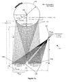
- Figure 1a illustrates an embodiment of the 3D-imaging apparatus 101, which is arranged to image an object 111 having a three-dimensional shape (i.e. the points on its surface do not all lie on a two-dimensional common plane).
- the imaging apparatus 101 has: (i) two two-dimensional ('2D') arrays 103a, 103b of reflective elements 105; (ii) an image-capturing device (shown in Figure 1a as a charge-coupled device 107); and (iii) a processor (not shown).
- An example of the processor may be a Dell Dimension T7400 Workstation.
- the arrays 103a, 103b are positioned to face towards the object 111 to be imaged.
- the shape of the object 111 is initially unknown, but it will be assumed in the following discussion that it approximates a portion of the surface of a circular cylinder having a radius denoted by "r" and a length direction which in Figure 1a is the direction into the page.
- the cylinder is referred to as the "baseline” 109, and appears as a circle in Figure 1a which is a cross-section of the cylinder.
- the baseline 109 could be a cylinder with an axis parallel to the height direction of the person.
- the baseline may have a different selected shape. For example, to take a photograph of a human head it may be better for the baseline to be an elliptic cylinder instead of a circular cylinder.
- the user initially estimates a length direction of the object 111, derives the baseline 109, and positions the arrays 103a, 103b such that they lie in a common plane a distance d from the baseline 109.
- the common plane includes (i) the length direction of the object 111 (i.e. the direction into the page) and (ii) a second direction normal to the length direction of the object (i.e. the left-right direction in Figure 1a ).
- the arrays 103a, 103b are spaced apart in the second direction.
- the distance of the common plane from the centre line of the baseline 109 is d+r.
- the arrays 103a, 103b each has a finite extension in the direction which is left-right in Figure 1a , and also an extension in the direction which is parallel to the longitudinal axis of the direction into the page in Figure 1a . That is, each of the arrays 103a, 103b is viewed "edge on" in Figure 1a .
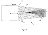
- Figure 1b shows the same apparatus 101 looking in the direction which is left-right in Figure 1a . In this view also, the arrays 103a, 103b are viewed edge-on.
- each of the arrays 103a, 103b may be a two-dimensional rectangular array of reflective elements 105. That is, each array 103a, 103b may be considered either a set of columns of reflective elements 105, which each extends in the length direction of the object 111, or as a set of rows of reflective elements 105 which each extends in the left-right direction of Figure 1 .
- Figures 1a and 1b illustrate the case that in each of the arrays 103a, 103b, there are 19x19 reflective elements 105 extending in the length direction of the object 111 as well as in the left-right direction of Figure 1a , but in other embodiments there may be other numbers of reflective elements 105.
- the charge-coupled device 107 is arranged relative to the two sets 103a, 103b of reflective elements 105 to capture virtual images of the object 111 as reflected by the reflective elements 105.
- the rays reflected by the elements 105 towards the charge-coupled device 107 converge at a perpendicular distance ' e ' from the common plane of the reflective elements 105 and at an offset distance from the rightmost reflective element 105, as seen from Figure 1a .
- the charge-coupled device 107 has sufficient resolution to capture all the rays of light.
- the relative arrangement of the reflective elements 105, the charge-coupled device 107 and the cylindrical baseline 109 is measured by a level gauge (not shown). However, other measurement tools such as a laser measurement meter may also be used.
- the reflective elements 105 are holographic optical elements.
- the element 105 has a notional normal direction indicated by the dashed line.
- the holographic optical element 105 is capable of only one reflection: reflecting a ray incident on the element 105 which is incident on the element 105 in one predetermined direction (at an angle from the normal direction marked as "p") so as to produce an outgoing ray in another predetermined direction (at an angle from the normal direction marked as "q"). These two directions lie in the plane of the paper in Figure 1a .
- i the index
- the corresponding sampling point 113 is in the direction relative to the optical element 105 which is denoted b i in Figure 1a . Note that this angle is different for each of the pairs of optical elements 105.
- the i -th sampling point 113 is the point on the baseline 109 such that, for each of the i -th holographic optical elements 105, angle b i is approximately equal to the corresponding angle marked as "p" in Figure 2a .
- each of the holographic optical elements 105 from each of the sets 103a, 103b reflects a different ray of light into the charge-coupled device 107.
- the leftmost holographic optical element 105 in each set 103a, 103b reflects the ray emanating from the leftmost sampling point 113 towards the charge-coupled device 107; the second leftmost holographic optical element 105 in each set 103a, 103b reflects the ray emanating from the second leftmost sampling point 113 towards the charge-coupled device 107, and so forth.
- angles "p” and "q” are different for the i -th pair of optical elements, and are also different for different indices i. That is, if p i,set1 /q i,set1 and p i,set2 /q i,set2 represent the angles of incidence and reflection of the holographic optical elements 105 of the arrays 103a and 103b respectively, then p i,set1 is different from p i,set2, and likewise, q i,set1 is different from q i,set2. Also, respective values of p i,set1 are different for different indices i, and similarly, respective values of q i,set1 are also different for different indices i.
- the angular position of the i -th sampling point on the baseline 109 is denoted a i .
- the rays reflected by the respective i -th pair of holographic optical elements 105 are transmitted to the charge coupled device 107 at an angle denoted by k i which is different for each of the pairs of holographic optical elements, and which for each of those holographic optical elements is approximately equal to the corresponding value of 90°-h (where h is as denoted in Figure 2a ).
- each column of the holographic optical elements 105 is responsible for the charge coupled device 107 receiving an image of a corresponding a strip of the object 111 which is approximately a straight line extending parallel to the axis of the baseline 109, and for each such strip of the object 111 the charge coupled device 107 will receive two different images from respective columns of the respective arrays 103a, 103b (not necessarily from optical elements 105 having the same value of i).
- the resolution of the object 111 as reconstructed by the 3D-imaging apparatus 101 will depend on such factors as: (i) the number of reflective elements 105 in each set 103a, 103b for a certain reference baseline; and (ii) the coverage of the object 111 in 3D space for a certain number of reflective elements in each set 103a, 103b.
- the 3D-imaging apparatus 101 may be configured to reconstruct an object outline within a specified angle range, so that the rays emanating from the reference baseline 109 represent the corresponding ray emanating from the object 111 at that specified angle range. This may ensure that the resolution of the object is not compromised by a limited number of reflective elements, for example.
- Figure 2b shows how one of the holographic optical elements 105, made up of photopolymer material, is constructed using a laser source 201 or any coherent light source, after pre-determining a desired angle of incidence p and a desired angle of reflection q.
- a beam splitter 203 splits a laser beam 205 from the laser source 201 into first and second laser sub-beams 205a, 205b.
- the first laser sub-beam 205a intersects the holographic optical element 105 at the desired angle of incidence p, while the second laser sub-beam 205b is reflected by a mirror 209 and intersects the holographic optical element 105 at the desired angle of reflection q.
- the reflection characteristics of the holographic optical element 105 can be changed during construction by varying the angle of the laser beam 205 in relation to the photopolymer material.
- the holographic optical element 105 has the same reflection characteristics as a flat mirror plane that is titled at an angle to achieve the desired angle of incidence p and the angle of reflection q . Accordingly, any type of mirror-like reflective element can be used in place of the holographic optical elements 105.
- Figure 3 illustrates the arrangement of flat mirrors 301 as the reflective elements. In this case, each of the flat mirrors 301 would have to be individually positioned with its own respective tilt angle to achieve the correct reflection. Therefore, unique tilt angles of the flat mirrors 301 are visually apparent.
- the holographic optical elements 105 do not need to tilt.
- the captured data sets are normalised by resizing pixel columns of one of the data sets by a "normalisation factor", based on a ratio of the perpendicular distances - relative to the straight plane in which the holographic optical elements are arranged - between the charge-coupled device 107 and the corresponding pixels of the data sets. Since the relative arrangement of the holographic elements 105, the cylindrical baseline 113 and the charge-coupled device 107 is known, the normalisation factor can be derived by standard trigonometric calculations, as shown in Figure 4 .
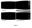
- the upper row shows the data sets captured by the image-capturing device 107 from the respective sets 103a, 103b of holographic optical elements 105.
- the upper row shows the two captured images: the left image ('data set 2') is captured from the right set 103b of holographic optical elements 105 as viewed from Figure 1 , whereas the right image ('data set 1') is captured from the left set 103a of holographic optical elements 105 as viewed from Figure 1 also.
- the processor is operable to locate matching columns in these data sets. This may be done by comparing an epipolar line in one of the data sets against a corresponding epipolar line in the other data set. More specifically, the processor derives the pairs of pixels respectively in the left and right images in the lower part of Figure 5 which correspond to the same point on the object 111. Note that the two pixels which correspond to a given point on the object 111 will usually lie in the same row of the two images in the lower part of Figure 5 .
- FIG. 6a and 6b shows how each pixel of the 7 -th row of the left image (the image corresponding to data set 1) is matched with a corresponding pixel of the 7 -th row of the right image (the image corresponding to data set 2).
- the pixel matching can be performed using any known match method such as dynamic programming, window-based, or graph-cut.
- the matching of the data sets may be done by the processor by comparing an epipolar line in one of the data sets against a plurality of epipolar lines in the other data set. That is, each pixel in a given a particular row of one of the images may be matched against with a respective pixel from any of multiple rows in the other respective image captured. This may improve the robustness of the epipolar matching, since it accommodates some errors in epipolar constraints used during the pixel matching.
- Figure 8 shows 10 pairs of pixels matched between the 5 th rows of the data sets. Accordingly, the processor will identify 10 intersection points of pairs of the rays, to determine 10 points of an outline of the object 111 in the 3D space relative to the cylindrical baseline 109. By connecting these 10 points of the outline of the object 111, a partial 3D image of the object 111 can be reconstructed by the 3D-imaging apparatus 101. By reconstructing different object outlines in relation to the corresponding rows of the data sets, a 3D image of the object 111 is accordingly reconstructed by the 3D-imaging apparatus 101.
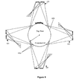
- Figure 9 illustrates four instances of the 3D-imaging apparatus 101 arranged to capture an "all-round" multiple-perspective views of an object. Adjacent instances of the 3D-imaging apparatus 101 are arranged around the centre of the baseline 109 at offsets of 90 degrees in order to capture an all-round multiple-perspective view of the object.
- Figure 10 is a flow chart showing a method of generating a 3D image of an object, which comprises the steps of:
- the step of locating 1011 the plurality of pairs of matching points in the respective virtual images comprises the steps of:
- step of using 1012 the plurality of determined locations of the object comprises the steps of:
- the method may comprise the further step of reconstructing a 3D model of the object based on different object outlines determined by the steps above.
- Figures 11a and 11b show respective top and side views of another embodiment of the 3D-imaging apparatus 1101, whereby holographic optical elements 1103 of the two different sets 1105a, 1105b are interleaved. Also the charge-coupled device 1107 is arranged above the holographic optical elements 1103, instead of at an offset distance from the rightmost HOE as is the case shown in Figure 1 . This arrangement may provide a compact structure of the 3D-imaging apparatus 1101.
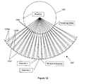
- Figure 12 shows a further embodiment of the 3D-imaging apparatus 1201.
- holographic optical elements 1203 from the two different sets 1205a, 1205b are also interleaved.
- the sets 1205a, 1205b of the holographic optical elements 1203 are arranged not on a common plane but on a common cylindrical surface coaxial with the cylindrical baseline 1207. Due to the parallel arrangement of the holographic optical elements 1203 relative to the cylindrical baseline 1207, rays emanate from the sampling points 1209 to the holographic optical elements 1203 at an angle normal to that cylindrical baseline 1207.
- this may reduce the problem of occlusion.
- the charged coupled device (not shown in Fig. 12 ) can be placed at the centre of the cylindrical baseline 1207, if that location is not occupied by the object to be imaged.
- the arrangement of the data sets is symmetrical.
- the normalisation step is not necessary since the pair of rays emitted from each point of the object to be imaged travel the same distance to the charge coupled device.
- Figures 13a and 13b illustrate the top and side view of yet another embodiment of the 3D-imaging apparatus 1301.
- holographic optical elements 1303 of the 3D-imaging apparatus 1301 of the two different sets 1305a, 1305b are again interleaved.
- each of the holographic optical elements 1303 from the set 1305b is laterally offset at a distance towards the right compared to its corresponding optical element 1303 from the set 1305a, and this distance is greater than the spacing between neighbouring optical elements 1303 in either of the sets 1305a, 1305b.
- reference baselines of different geometries may also be used so long as they roughly resemble the object outlines in the 3D space.
- the accuracy of the reconstructed object outlines and/or the 3D models depends on the number of reflective elements in each set, there may be tens of reflective elements in each set, or it may be in the range of hundred or even thousands.
- the charge-coupled device 107 may be a pin-hole camera. Alternatively, the charge-coupled device 107 may be a digital single-lens reflect (DSLR) camera.
- DSLR digital single-lens reflect
- the reflective elements may be formed by applying precision machining on a solid block.
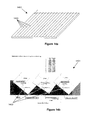
- Figure 14a illustrates a perspective view of a solid block 1401 on which precision machining has been applied. Note that the number of machined surfaces 1403 has been reduced to simplify illustration. Each machined surface 1403 of the solid block 1401 has a unique tilt angle and a mirror for reflecting different perspective view of an object.
- Figure 14b illustrates a cross-section B-B' of the solid block 1401 shown in Figure 14a . It can be seen that two sets of reflective elements are interleaved in Figure 14b , with the leftmost machined surface 1403 corresponding to the first reflective element 105 (i.e.
- the element pitch (i.e. the separation distance) between the corresponding reflective elements 105 of the arrays 103a, 103b is 0.5 mm, whilst the element pitch between successive reflective elements 105 of each array 103a, 103b is 1 mm.
- the accuracy (i.e. tolerance specifications) of the precision machine should be evaluated to ensure the precision machine meets the requirements.
- CNC machines and profile grinders are some options that may meet these requirements.
- CNC machining mirror-coating may be necessary for the machined surfaces to reflect the various perspective views of an object.
- the ground surfaces may however be sufficiently smooth to reflect the various perspective views of an object such that the additional mirror-coating is typically not required.
- the holographic optical elements may offer a lot of flexibility in terms of design and implementation which precision machining of the solid block may not offer, the use of a machined block in place of the holographic optical elements may offer a more practical implementation compared to the use of the holographic optical elements. This is because so long as the accuracy of the precision machining is guaranteed by the precision machine, the accuracy of tilt angles of respective machined surfaces of the solid block may be ensured.
- the holographic optical elements issues like the diffraction efficiency of the polymer being less than unity and the three colours (i.e. red, green and blue) not being convergent to a common point would have to be addressed. Assuming these issues are sufficiently addressed, the use of the holographic optical elements is more preferred than the precision machining of the solid block.
Landscapes
- Engineering & Computer Science (AREA)
- Multimedia (AREA)
- Signal Processing (AREA)
- Physics & Mathematics (AREA)
- General Physics & Mathematics (AREA)
- Optics & Photonics (AREA)
- Length Measuring Devices By Optical Means (AREA)
- Image Processing (AREA)
- Studio Devices (AREA)
- Optical Elements Other Than Lenses (AREA)
- Stereoscopic And Panoramic Photography (AREA)
- Diffracting Gratings Or Hologram Optical Elements (AREA)
- Testing, Inspecting, Measuring Of Stereoscopic Televisions And Televisions (AREA)
- Holo Graphy (AREA)
Applications Claiming Priority (1)
| Application Number | Priority Date | Filing Date | Title |
|---|---|---|---|
| SG2009082041A SG172487A1 (en) | 2009-12-07 | 2009-12-07 | A three-dimensional imaging apparatus and a method of generating a three-dimensional image of an object |
Publications (1)
| Publication Number | Publication Date |
|---|---|
| EP2334091A2 true EP2334091A2 (de) | 2011-06-15 |
Family
ID=43754944
Family Applications (1)
| Application Number | Title | Priority Date | Filing Date |
|---|---|---|---|
| EP10015159A Withdrawn EP2334091A2 (de) | 2009-12-07 | 2010-11-30 | Dreidimensionales Bildgebungsgerät und Verfahren zur Erzeugung eines dreidimensionalen Bildes eines Objekts |
Country Status (5)
| Country | Link |
|---|---|
| US (1) | US8350893B2 (de) |
| EP (1) | EP2334091A2 (de) |
| JP (1) | JP2011120235A (de) |
| CN (1) | CN102088617B (de) |
| SG (1) | SG172487A1 (de) |
Cited By (1)
| Publication number | Priority date | Publication date | Assignee | Title |
|---|---|---|---|---|
| CN109412073A (zh) * | 2018-08-14 | 2019-03-01 | 武汉松盛光电科技有限公司 | 一种激光发射装置及用于清理高压线飘挂物的装置 |
Families Citing this family (5)
| Publication number | Priority date | Publication date | Assignee | Title |
|---|---|---|---|---|
| WO2009070121A1 (en) * | 2007-11-30 | 2009-06-04 | Hamed Hamid Muhammed | Miniaturized all-reflective holographic fourier transform imaging spectrometer based on a new all-reflective interferometer |
| US20120022357A1 (en) * | 2010-04-26 | 2012-01-26 | David Chang | Medical emitter/detector imaging/alignment system and method |
| US20140132736A1 (en) * | 2010-11-01 | 2014-05-15 | Hewlett-Packard Development Company, L.P. | Image capture using a virtual camera array |
| WO2012060814A1 (en) * | 2010-11-01 | 2012-05-10 | Hewlett-Packard Development Company, L.P. | Image display using a virtual projector array |
| JP5977591B2 (ja) * | 2012-06-20 | 2016-08-24 | オリンパス株式会社 | 画像処理装置及びそれを備えた撮像装置、画像処理方法、並びに画像処理プログラムを記録したコンピュータ読み取り可能な記録媒体 |
Family Cites Families (22)
| Publication number | Priority date | Publication date | Assignee | Title |
|---|---|---|---|---|
| US4893183A (en) * | 1988-08-11 | 1990-01-09 | Carnegie-Mellon University | Robotic vision system |
| US5841441A (en) * | 1996-01-19 | 1998-11-24 | Virtus Corporation | High-speed three-dimensional texture mapping systems and methods |
| US6720949B1 (en) * | 1997-08-22 | 2004-04-13 | Timothy R. Pryor | Man machine interfaces and applications |
| CN1210944C (zh) | 1998-10-02 | 2005-07-13 | 旺宏电子股份有限公司 | 用于防止梯形失真的方法和装置 |
| US6491400B1 (en) | 2000-10-24 | 2002-12-10 | Eastman Kodak Company | Correcting for keystone distortion in a digital image displayed by a digital projector |
| US7027530B2 (en) * | 2001-04-11 | 2006-04-11 | Atheros Communications, Inc. | Method and apparatus for maximizing receiver performance utilizing mid-packet gain changes |
| ATE374387T1 (de) * | 2001-04-20 | 2007-10-15 | Thomson Licensing | Dreidimensionales fotografisches gerät |
| JP2002352271A (ja) * | 2001-05-28 | 2002-12-06 | Olympus Optical Co Ltd | 3次元画像取得装置 |
| JP4931288B2 (ja) | 2001-06-08 | 2012-05-16 | ペンタックスリコーイメージング株式会社 | 画像検出装置と絞り装置 |
| EP1333687A1 (de) | 2002-02-01 | 2003-08-06 | Thomson Licensing S.A. | Autostereoskopische Anzeigevorrichtung und Bildaufnahmevorrichtung |
| JP2003296740A (ja) * | 2002-04-08 | 2003-10-17 | Victor Co Of Japan Ltd | オブジェクト監視方法及びオブジェクト監視カメラ装置 |
| US6877863B2 (en) | 2002-06-12 | 2005-04-12 | Silicon Optix Inc. | Automatic keystone correction system and method |
| US7175285B2 (en) | 2003-07-29 | 2007-02-13 | Sharp Laboratories Of America, Inc. | Projection system that adjusts for keystoning |
| US20090009592A1 (en) * | 2004-10-01 | 2009-01-08 | Sharp Kabushiki Kaisha | Three-Dimensional Image Forming System |
| CN100492170C (zh) * | 2005-01-12 | 2009-05-27 | 中国科学院沈阳自动化研究所 | 一种全向立体视觉成像方法及装置 |
| US20060204125A1 (en) | 2005-03-09 | 2006-09-14 | Kempf Jeffrey M | Multi-dimensional keystone correction image projection system and method |
| CA2600926C (en) * | 2005-03-11 | 2009-06-09 | Creaform Inc. | Auto-referenced system and apparatus for three-dimensional scanning |
| KR100708352B1 (ko) * | 2006-03-07 | 2007-04-18 | 한국과학기술원 | 모아레 원리의 2π 모호성과 위상천이 수단이 없도록실시되는 3차원 형상 측정장치 및 그 방법 |
| US20070248260A1 (en) | 2006-04-20 | 2007-10-25 | Nokia Corporation | Supporting a 3D presentation |
| DE102008033213A1 (de) * | 2007-07-16 | 2009-01-22 | Carl Zeiss Smt Ag | Kombiblende für katoptrische Projektionsanordnung |
| KR100937922B1 (ko) * | 2009-02-12 | 2010-01-21 | 엔지비스 주식회사 | 구형 물체의 비행정보 측정 시스템 및 방법 |
| CN101546111A (zh) * | 2009-04-30 | 2009-09-30 | 浙江大学 | 单相机双目宽基线折反射全景立体成像方法及其装置 |
-
2009
- 2009-12-07 SG SG2009082041A patent/SG172487A1/en unknown
-
2010
- 2010-11-23 US US12/952,836 patent/US8350893B2/en not_active Expired - Fee Related
- 2010-11-25 JP JP2010262592A patent/JP2011120235A/ja active Pending
- 2010-11-30 EP EP10015159A patent/EP2334091A2/de not_active Withdrawn
- 2010-12-07 CN CN201010576241.2A patent/CN102088617B/zh not_active Expired - Fee Related
Non-Patent Citations (1)
| Title |
|---|
| None |
Cited By (2)
| Publication number | Priority date | Publication date | Assignee | Title |
|---|---|---|---|---|
| CN109412073A (zh) * | 2018-08-14 | 2019-03-01 | 武汉松盛光电科技有限公司 | 一种激光发射装置及用于清理高压线飘挂物的装置 |
| CN109412073B (zh) * | 2018-08-14 | 2023-12-22 | 武汉松盛光电科技有限公司 | 一种激光发射装置及用于清理高压线飘挂物的装置 |
Also Published As
| Publication number | Publication date |
|---|---|
| US20110141243A1 (en) | 2011-06-16 |
| CN102088617B (zh) | 2014-11-12 |
| CN102088617A (zh) | 2011-06-08 |
| SG172487A1 (en) | 2011-07-28 |
| US8350893B2 (en) | 2013-01-08 |
| JP2011120235A (ja) | 2011-06-16 |
Similar Documents
| Publication | Publication Date | Title |
|---|---|---|
| US8350893B2 (en) | Three-dimensional imaging apparatus and a method of generating a three-dimensional image of an object | |
| US8290358B1 (en) | Methods and apparatus for light-field imaging | |
| EP4372447B1 (de) | Vorrichtung, verfahren und system zur erzeugung dynamischer projektionsmuster in einer kamera | |
| JP5635218B1 (ja) | 空間コード化スライド画像に対するパターンのアライメント方法およびシステム | |
| CN111750806A (zh) | 一种多视角三维测量系统及方法 | |
| US10964107B2 (en) | System for acquiring correspondence between light rays of transparent object | |
| Sturm et al. | How to compute the pose of an object without a direct view? | |
| JP2013038775A (ja) | 高速反射屈折式ライトフィールドレンダリングのための光線画像モデル化 | |
| CN112381921B (zh) | 一种边缘重建方法及系统 | |
| CN107995434A (zh) | 图像获取方法、电子装置和计算机可读存储介质 | |
| CN112945141A (zh) | 基于微透镜阵列的结构光快速成像方法及系统 | |
| WO2017013068A1 (fr) | Procédé et dispositif d'affichage de scène tridimensionnelle sur une surface d'affichage de forme arbitraire non plane | |
| CN118482665A (zh) | 一种偏振自旋转滤光的结构光三维测量方法及设备 | |
| CN120953480A (zh) | 四目结构光立体视觉成像方法 | |
| KR20240118827A (ko) | 구강 내 스캐너, 구강 내 스캐닝 시스템, 구강 내 스캔을 수행하는 방법 및 컴퓨터 프로그램 제품 | |
| CN114556913B (zh) | 3d光场显示器的光学设计和优化技术 | |
| CN117570876A (zh) | 基于宽场多孔径合成相位偏折术的高反射自由曲面检测方法 | |
| EP2533199B1 (de) | Bildgebungssystem mit Mehrfachansicht | |
| KR102317836B1 (ko) | 회절 격자를 이용한 3차원 이미지 재구성 방법 및 장치 | |
| Pagani et al. | Dense 3D Point Cloud Generation from Multiple High-resolution Spherical Images. | |
| US11822287B1 (en) | Binocular holographic machine vision system and method for identifying locations of target elements | |
| CN115451866B (zh) | 基于光场等效相机阵列模型的高反光表面三维测量方法 | |
| KR20240092912A (ko) | 디스플레이에 대해 소정의 기울기를 가진 광학 렌즈를 이용한 라이트 필드 디스플레이를 위해 라이트 필드 영상을 생성하는 장치, 방법 및 컴퓨터 프로그램 | |
| CN116358450A (zh) | 一种基于机械式结构光高速投影的三维测量系统和方法 | |
| KR20230077143A (ko) | 카메라에 의해 생성된 그래픽스 데이터의 품질 개선 방법 |
Legal Events
| Date | Code | Title | Description |
|---|---|---|---|
| PUAI | Public reference made under article 153(3) epc to a published international application that has entered the european phase |
Free format text: ORIGINAL CODE: 0009012 |
|
| 17P | Request for examination filed |
Effective date: 20101130 |
|
| AK | Designated contracting states |
Kind code of ref document: A2 Designated state(s): AL AT BE BG CH CY CZ DE DK EE ES FI FR GB GR HR HU IE IS IT LI LT LU LV MC MK MT NL NO PL PT RO RS SE SI SK SM TR |
|
| AX | Request for extension of the european patent |
Extension state: BA ME |
|
| STAA | Information on the status of an ep patent application or granted ep patent |
Free format text: STATUS: THE APPLICATION HAS BEEN WITHDRAWN |
|
| 18W | Application withdrawn |
Effective date: 20141209 |