EP2333519B1 - Device for carrying out corrosion tests on steel materials - Google Patents
Device for carrying out corrosion tests on steel materials Download PDFInfo
- Publication number
- EP2333519B1 EP2333519B1 EP10075722.8A EP10075722A EP2333519B1 EP 2333519 B1 EP2333519 B1 EP 2333519B1 EP 10075722 A EP10075722 A EP 10075722A EP 2333519 B1 EP2333519 B1 EP 2333519B1
- Authority
- EP
- European Patent Office
- Prior art keywords
- test
- ring
- specimen
- testing
- force
- Prior art date
- Legal status (The legal status is an assumption and is not a legal conclusion. Google has not performed a legal analysis and makes no representation as to the accuracy of the status listed.)
- Active
Links
- 238000012360 testing method Methods 0.000 title claims description 41
- 238000005260 corrosion Methods 0.000 title claims description 13
- 230000007797 corrosion Effects 0.000 title claims description 13
- 239000000463 material Substances 0.000 title claims description 6
- 229910000831 Steel Inorganic materials 0.000 title claims description 5
- 239000010959 steel Substances 0.000 title claims description 5
- UCKMPCXJQFINFW-UHFFFAOYSA-N Sulphide Chemical compound [S-2] UCKMPCXJQFINFW-UHFFFAOYSA-N 0.000 claims description 5
- 238000005336 cracking Methods 0.000 claims description 5
- 239000012085 test solution Substances 0.000 description 3
- FAPWRFPIFSIZLT-UHFFFAOYSA-M Sodium chloride Chemical compound [Na+].[Cl-] FAPWRFPIFSIZLT-UHFFFAOYSA-M 0.000 description 2
- 238000005259 measurement Methods 0.000 description 2
- 238000010998 test method Methods 0.000 description 2
- RWSOTUBLDIXVET-UHFFFAOYSA-N Dihydrogen sulfide Chemical compound S RWSOTUBLDIXVET-UHFFFAOYSA-N 0.000 description 1
- 239000013078 crystal Substances 0.000 description 1
- 239000007789 gas Substances 0.000 description 1
- 238000009434 installation Methods 0.000 description 1
- 125000000896 monocarboxylic acid group Chemical group 0.000 description 1
- 239000012047 saturated solution Substances 0.000 description 1
- 239000011780 sodium chloride Substances 0.000 description 1
- 238000009864 tensile test Methods 0.000 description 1
- 238000004154 testing of material Methods 0.000 description 1
Images
Classifications
-
- G—PHYSICS
- G01—MEASURING; TESTING
- G01N—INVESTIGATING OR ANALYSING MATERIALS BY DETERMINING THEIR CHEMICAL OR PHYSICAL PROPERTIES
- G01N17/00—Investigating resistance of materials to the weather, to corrosion, or to light
- G01N17/04—Corrosion probes
-
- G—PHYSICS
- G01—MEASURING; TESTING
- G01N—INVESTIGATING OR ANALYSING MATERIALS BY DETERMINING THEIR CHEMICAL OR PHYSICAL PROPERTIES
- G01N17/00—Investigating resistance of materials to the weather, to corrosion, or to light
- G01N17/006—Investigating resistance of materials to the weather, to corrosion, or to light of metals
-
- G—PHYSICS
- G01—MEASURING; TESTING
- G01N—INVESTIGATING OR ANALYSING MATERIALS BY DETERMINING THEIR CHEMICAL OR PHYSICAL PROPERTIES
- G01N2203/00—Investigating strength properties of solid materials by application of mechanical stress
- G01N2203/02—Details not specific for a particular testing method
- G01N2203/022—Environment of the test
- G01N2203/0236—Other environments
- G01N2203/024—Corrosive
Definitions
- the invention relates to a device for carrying out corrosion tests on steel materials.
- the invention relates in particular to a device for carrying out a corrosion test for testing for sulfide stress corrosion cracking (SSC), as described, for. B. from the NACE standard TM0177-2005 is known, but this device is in principle applicable to any other test for corrosion or material testing.
- This test method was also reported in ": BOSCH et al .: Improved Understanding of test variables in the tensile test, International Corrosion Conference Series, National Ass. Of Corrosion Engineers, US, Mar. 22, 2009, pp. 09096/11, XP009144830, ISSN: 0361-4409 ".
- test for sulfide stress corrosion cracking is performed according to the specification of the NACE standard with a test solution consisting of a H 2 S saturated solution of NaCl and CH 3 COOH.
- test requirements for the test specimen immersed in the test solution and under tension provide that the specimen should not break within the test duration of 720 hours.
- test itself is carried out with test equipment as proposed in the NACE Standard TM0177-2005.
- a clamped by means of a clamping element in a test ring sample in a test solution is acted upon by a defined test load.
- the sample is provided at both ends with a thread in order to screw or fix it at one end in a threaded nut fixed to the inner circumference of the ring.
- the clamping element is passed through a hole in the ring up to a serving as a support on the ring surface stop and connected the other end of the sample with a threaded nut attached to the clamping element.
- test load is determined in accordance with NACE standard indirectly via the measured elastic ring deformation, the deviation from the diameter in the untensioned state, for example, measured by micrometer screws and converted into a tensile force.
- the object of the invention is to provide a device for carrying out corrosion tests on steel materials, for example for testing for sulfide stress corrosion cracking, which allows a more accurate determination of the test load and thus more accurate test results.
- the great advantage of the device according to the invention is that the direct measurement of force on the sample during the deformation of the ring an exact determination of the test load acting on the sample is possible and therefore much more accurate test results are achieved with a much higher significance.
- the installation of the force measuring device is very simple and inexpensive to implement, since only a standard dynamometer, such as a piezoelectric crystal, must be installed in the flow direction of the force of the clamping element. It is advantageous to arrange the dynamometer directly above the support.
- test setup and design are in line with the NACE standard TM0177-2005 testing device, which has been expanded to include the force measuring device, to ensure conformity with the NACE standard.
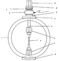
- the device consists of a test ring 1 having the following dimensions for testing in accordance with the NACE Test Standard TM0177-2005 in this example: 300 mm diameter, 50 mm width, 12-15 mm wall thickness.
- the test ring 1 is turned off on the inner and outer surfaces, so that it has a uniform wall thickness over the entire circumference.
- a respective support plate 2, 2 ' is welded opposite each other, which is ground plane-parallel in order to obtain an exact bearing surface for a secure position of the test ring 1 and for the educakraftaufbringung on the sample 3.
- the sample 3 itself is provided at both ends with a thread, not shown, to connect at one end to the ring inside in the region of the support plate 2 'with a threaded nut 4' fixed there and at the other end with the threaded nut 4 of a clamping element 5 can.
- the threaded nut 4 is formed as a union nut.
- the other end of the clamping element 5 protrudes with such a length from the bore that further provided with holes components can be attached thereto, which are supported on the total support plate 2.
- the protruding from the ring 1 end of the clamping element 5 is provided with a thread on which a trained as a hexagon and provided with a through hole clamping head 8 is screwed.
- a support for the clamping element 5 is first arranged on the support plate 2, which is formed according to the invention as a spherical bearing 6.
- a force measuring device 9 advantageously consisting of a piezo load cell and a measuring amplifier not shown here to measure directly during the tensioning applied to the sample 3 scholarkraft can ,
- spherical bearing 6 ' is arranged to further minimize friction and dislocations.
Landscapes
- Life Sciences & Earth Sciences (AREA)
- Biodiversity & Conservation Biology (AREA)
- Ecology (AREA)
- Environmental & Geological Engineering (AREA)
- Environmental Sciences (AREA)
- Physics & Mathematics (AREA)
- Health & Medical Sciences (AREA)
- Chemical & Material Sciences (AREA)
- Analytical Chemistry (AREA)
- Biochemistry (AREA)
- General Health & Medical Sciences (AREA)
- General Physics & Mathematics (AREA)
- Immunology (AREA)
- Pathology (AREA)
- Testing Resistance To Weather, Investigating Materials By Mechanical Methods (AREA)
- Investigating Strength Of Materials By Application Of Mechanical Stress (AREA)
Description
Die Erfindung betrifft eine Vorrichtung zur Durchführung von Korrosionstests an Stahlwerkstoffen.The invention relates to a device for carrying out corrosion tests on steel materials.
Wenngleich sich die Erfindung insbesondere auf eine Vorrichtung zur Durchführung eines Korrosionstests zur Prüfung auf Sulfidspannungsrisskorrosion (SSC) bezieht, wie er z. B. aus dem NACE Standard TM0177-2005 bekannt ist, ist diese Vorrichtung aber im Grundsatz auch auf jeden anderen Test zur Korrosions- oder Werkstoffprüfung anwendbar.
Ober diese Testmethode wurde auch berichtet in ":
This test method was also reported in ":
Die Sulfidspannungsrisskorrosion an Stahlwerkstoffen stellt ein ernstes Problem insbesondere für Ölfeldrohre dar, die zur Förderung von Schwefelwasserstoff enthaltendem Öl oder Gas ausgelegt werden sollen.Sulphide stress corrosion cracking on steel materials poses a serious problem, in particular for oilfield pipes designed to deliver oil or gas containing hydrogen sulphide.
Bei diesem in der Fachwelt allgemein anerkannten Testverfahren wird die Prüfung auf Sulfidspannungsrisskorrosion nach der Spezifikation des NACE Standards mit einer Prüflösung bestehend aus einer mit H2S gesättigten Lösung aus NaCl und CH3COOH durchgeführt.In this test procedure generally recognized in the art, the test for sulfide stress corrosion cracking is performed according to the specification of the NACE standard with a test solution consisting of a H 2 S saturated solution of NaCl and CH 3 COOH.
Die Prüfanforderungen für den in die Prüflösung eingetauchten und unter Zugspannung stehenden Prüfling sehen vor, dass innerhalb der Testdauer von 720 Stunden der Prüfling nicht brechen soll.The test requirements for the test specimen immersed in the test solution and under tension provide that the specimen should not break within the test duration of 720 hours.
Die Prüfung selbst wird mit Prüfvorrichtungen wie im NACE Standard TM0177-2005 vorgeschlagen durchgeführt, bei der z. B. eine mittels eines Spannelementes in einem Prüfring eingespannte Probe in einer Prüflösung durch eine definierte Prüflast beaufschlagt wird.The test itself is carried out with test equipment as proposed in the NACE Standard TM0177-2005. B. a clamped by means of a clamping element in a test ring sample in a test solution is acted upon by a defined test load.
Hierzu ist die Probe an beiden Enden mit einem Gewinde versehen, um sie an einem Ende in eine am Innenumfang des Ringes befestigte Gewindemutter einschrauben bzw. fixieren zu können.For this purpose, the sample is provided at both ends with a thread in order to screw or fix it at one end in a threaded nut fixed to the inner circumference of the ring.
Zum Spannen der Probe wird das Spannelement durch eine Bohrung im Ring bis zu einem als Auflager auf der Ringoberfläche dienenden Anschlag hindurchgeführt und das andere Ende der Probe mit einer am Spannelement befestigten Gewindemutter verbunden.To clamp the sample, the clamping element is passed through a hole in the ring up to a serving as a support on the ring surface stop and connected the other end of the sample with a threaded nut attached to the clamping element.
Beim Spannen des Spannelementes wird über einen Spannkopf durch Drehbewegung auf die Probe eine Zugkraft aufgebracht und dabei der Prüfring elastisch verformt. Die Prüflast wird gemäß NACE Standard indirekt über die gemessene elastische Ringverformung ermittelt, wobei die Abweichung vom Durchmesser im ungespannten Zustand beispielsweise mittels Mikrometerschrauben gemessen und in eine Zugkraft umgerechnet wird.When tightening the clamping element, a tensile force is applied to the sample via a clamping head by rotational movement and the test ring is elastically deformed. The test load is determined in accordance with NACE standard indirectly via the measured elastic ring deformation, the deviation from the diameter in the untensioned state, for example, measured by micrometer screws and converted into a tensile force.
Gravierender Nachteil dieser Vorrichtung ist die Ungenauigkeit der ermittelten Prüfergebnisse, da sich Ungenauigkeiten bei der Messung der Ringverformung direkt auf die Prüflastermittlung auswirken und zusätzlich Temperaturschwankungen oder Inhomogenitäten im Werkstoff des Prüfrings zu ungenauen Prüflastermittlungen führen.A serious disadvantage of this device is the inaccuracy of the test results determined, since inaccuracies in the measurement of the ring deformation directly affect the Prüflasterbestimmung and in addition temperature fluctuations or inhomogeneities in the material of the test ring lead to inaccurate Prüflastermittelnlungen.
Aufgabe der Erfindung ist es, eine Vorrichtung zur Durchführung von Korrosionstests an Stahlwerkstoffen, beispielsweise zur Prüfung auf Sulfidspannungsrisskorrosion, anzugeben, welche eine genauere Ermittlung der Prüflast und damit genauere Prüfergebnisse ermöglicht.The object of the invention is to provide a device for carrying out corrosion tests on steel materials, for example for testing for sulfide stress corrosion cracking, which allows a more accurate determination of the test load and thus more accurate test results.
Erfindungsgemäß wird diese Aufgabe mit den Merkmalen des Anspruchs gelöst.According to the invention, this object is achieved with the features of the claim.
Der große Vorteil der erfindungsgemäßen Vorrichtung besteht darin, dass durch die direkte Kraftmessung an der Probe während der Verformung des Ringes eine exakte Bestimmung der auf die Probe einwirkenden Prüflast möglich ist und bedingt dadurch viel genauere Prüfergebnisse mir einer sehr viel höheren Aussagekraft erreicht werden.The great advantage of the device according to the invention is that the direct measurement of force on the sample during the deformation of the ring an exact determination of the test load acting on the sample is possible and therefore much more accurate test results are achieved with a much higher significance.
Zudem ist die Installation der Kraftmesseinrichtung sehr einfach und kostengünstig realisierbar, da nur ein handelsüblicher Kraftmesser, wie beispielsweise ein Piezo-Kristall, in Fließrichtung der Kraft des Spannelementes installiert werden muss. Günstig ist es dabei den Kraftmesser direkt oberhalb des Auflagers anzuordnen.In addition, the installation of the force measuring device is very simple and inexpensive to implement, since only a standard dynamometer, such as a piezoelectric crystal, must be installed in the flow direction of the force of the clamping element. It is advantageous to arrange the dynamometer directly above the support.
Der Testaufbau und die Ausführung entsprechen im Grundsatz der im NACE Standard TM0177-2005 vorgesehenen Prüfvorrichtung lediglich erweitert um die Kraftmesseinrichtung, so dass die Konformität mit dem NACE Standard gewährleistet ist.In principle, the test setup and design are in line with the NACE standard TM0177-2005 testing device, which has been expanded to include the force measuring device, to ensure conformity with the NACE standard.
Anhand einer schematischen Darstellung eines Ausführungsbeispiels wird die erfindungsgemäße Vorrichtung näher erläutert.On the basis of a schematic representation of an embodiment, the device according to the invention will be explained in more detail.
Die Vorrichtung besteht aus einem Prüfring 1 der für die Prüfung nach dem NACE Test Standard TM0177-2005 in diesem Beispiel folgende Abmessungen aufweist: 300 mm Durchmesser, 50 mm Breite, 12-15 mm Wanddicke.The device consists of a
Der Prüfring 1 ist an der Innen- und Außenoberfläche abgedreht, so dass er eine möglichst gleichmäßige Wanddicke über den gesamten Umfang hat. Am Außenumfang des Ringes 1 ist gegenüber liegend jeweils eine Auflageplatte 2, 2' angeschweißt, die planparallel geschliffen ist, um eine exakte Auflagefläche für einen sicheren Stand des Prüfrings 1 und für die Prüfkraftaufbringung auf die Probe 3 zu erhalten.The
Die Probe 3 selbst ist an beiden Enden mit einem hier nicht dargestellten Gewinde versehen, um sie an einem Ende an der Ringinnenseite im Bereich der Auflageplatte 2' mit einer dort befestigten Gewindemutter 4' und am anderen Ende mit der Gewindemutter 4 eines Spannelementes 5 verbinden zu können. Für ein leichteres Verbinden der Probe 3 mit dem Spannelement 5 ist die Gewindemutter 4 als Überwurfmutter ausgebildet.The
Zur Aufbringung der Zugkraft ist in die obere Auflageplatte 2 und in den Prüfring 1 eine durchgehende Bohrung eingebracht, durch die das stabförmige Spannelement 5 mit einem Ende mit Spiel hindurchgeführt und mit der Probe 3 über die Gewindemutter 4 verbunden wird. Das andere Ende des Spannelementes 5 ragt mit einer solchen Länge aus der Bohrung hervor, dass weitere mit Bohrungen versehene Bauelemente hierauf aufgesteckt werden können, die sich insgesamt auf der Auflageplatte 2 abstützen.To apply the tensile force is introduced into the
Das aus dem Ring 1 herausragende Ende des Spannelementes 5 ist mit einem Gewinde versehen, auf das ein als Sechskant ausgebildeter und mit einer Durchgangsbohrung versehener Spannkopf 8 aufgeschraubt ist.The protruding from the
Um Reibungen und Versetzungen beim Spannen des Prüfringes so gering wie möglich zu halten, ist auf der Auflageplatte 2 zunächst ein Auflager für das Spannelement 5 angeordnet, das erfindungsgemäß als Kalottenlager 6 ausgebildet ist.In order to keep friction and dislocations during clamping of the test ring as small as possible, a support for the
Erfindungsgemäß befindet sich in Flussrichtung der aufgebrachten Zugkraft des Spannelementes 5 zwischen Kalottenlager 6 und einem Kugellager 7 eine Kraftmesseinrichtung 9 vorteilhaft bestehend aus einer Piezo-Kraftmessdose und einem hier nicht dargestellten Messverstärker, um direkt während des Spannens die auf die Probe 3 aufgebrachte Prüfkraft messen zu können.According to the invention is located in the flow direction of the applied tensile force of the
Zwischen Spannkopf 8 und Kugellager 7 ist ein weiteres Kalottenlager 6' angeordnet, um Reibungen und Versetzungen weiter zu minimieren.Between
Durch einfache Drehbewegung des Spannkopfes 8 z. B. mittels eines Schraubenschlüssels relativ zum Spannelement 5 kann so über das Auflager auf der Auflageplatte 2 die Probe 3 mit einer Prüflast beaufschlagt werden.By simple rotation of the clamping head 8 z. B. by means of a wrench relative to the
Um ein Mitdrehen der Kraftmesseinrichtung 9 bei einer Drehbewegung des Spannkopfes 8 zu verhindern, ist der Spannkopf 8 mittelbar über das zweite Kalottenlager 6' und das Kugellager 7 auf der Kraftmesseinrichtung 9 aufgelagert.
Claims (2)
- Device for carrying out corrosion tests on steel materials, for example for testing for sulphide stress corrosion cracking according to the NACE Standard TM-0177-2005, consisting of a testing ring (1) in which a specimen (3) immersed in a testing solution can be subjected to a tensile force via a tensioning element (5) and the specimen (3) can be connected at one end to the testing ring (1) and at the other end to the tensioning element (5); wherein- the testing ring (1) is provided, in the region of a fixing location of the specimen (3), with an upper and a lower supporting plate (2, 2') at the outer circumference, the supporting plates (2, 2') being ground plane-parallel;- the tensioning element (5) is provided, for introducing force into the specimen, with a tensioning head (8) and a spherical bearing (6) arranged on the upper supporting plate (2);- in the flow direction of the applied tensile force of the tensioning element (5), there is arranged between the spherical bearing (6) and a ball bearing (7) a force measuring device (9) which directly measures the acting force; and- a further spherical bearing (6') is arranged between the ball bearing (7) and the tensioning head (8).
- Device according to Claim 1,
characterised
in that the force measuring device (9) is a piezoelectric load cell.
Applications Claiming Priority (1)
| Application Number | Priority Date | Filing Date | Title |
|---|---|---|---|
| DE102009056051A DE102009056051A1 (en) | 2009-11-26 | 2009-11-26 | Device for carrying out corrosion tests on steel materials |
Publications (2)
| Publication Number | Publication Date |
|---|---|
| EP2333519A1 EP2333519A1 (en) | 2011-06-15 |
| EP2333519B1 true EP2333519B1 (en) | 2016-06-29 |
Family
ID=43569475
Family Applications (1)
| Application Number | Title | Priority Date | Filing Date |
|---|---|---|---|
| EP10075722.8A Active EP2333519B1 (en) | 2009-11-26 | 2010-10-27 | Device for carrying out corrosion tests on steel materials |
Country Status (2)
| Country | Link |
|---|---|
| EP (1) | EP2333519B1 (en) |
| DE (1) | DE102009056051A1 (en) |
Families Citing this family (6)
| Publication number | Priority date | Publication date | Assignee | Title |
|---|---|---|---|---|
| CN103983559B (en) * | 2014-04-16 | 2016-07-13 | 深圳大学 | Reinforcing bar plays suggestion device and the reminding method of rust and chlorine ion concentration limit state |
| CN104697873B (en) * | 2015-03-06 | 2017-08-25 | 合肥通用机械研究院 | A kind of sulfide-stress cracking experimental rig |
| CN105865693A (en) * | 2016-06-15 | 2016-08-17 | 南阳师范学院 | Vibration reducer pre-tightening force test method and pre-tightening force calculation software |
| CN111141612B (en) * | 2020-01-21 | 2022-05-13 | 鞍钢股份有限公司 | Device and method for testing hydrogen sulfide stress corrosion resistance of oil well pipe |
| CN114878443A (en) * | 2020-09-01 | 2022-08-09 | 合肥通用机械研究院有限公司 | Bolt stress corrosion test method |
| CN112858147B (en) * | 2020-12-30 | 2022-08-23 | 龙口市新达精密滚动体有限公司 | High-precision real-time bearing steel ball detection device |
Family Cites Families (6)
| Publication number | Priority date | Publication date | Assignee | Title |
|---|---|---|---|---|
| DE2604641C2 (en) * | 1976-02-06 | 1978-02-02 | Bayer Ag, 5090 Leverkusen | Testing machine to determine the susceptibility of materials to stress corrosion cracking |
| FR2346709A1 (en) * | 1976-03-31 | 1977-10-28 | Aerospatiale | Test appts. partic. for corrosion testing - of test-pieces under tensile and bending strains, effected in same machine |
| FR2366558A1 (en) * | 1976-09-30 | 1978-04-28 | Saint Etienne Fondation Ind Mi | Accelerated tests for corrosion - are performed in corrosive atmosphere with strain force and temp. applied to sample |
| EP0517238B1 (en) * | 1991-06-06 | 1995-12-20 | Hitachi, Ltd. | Method of and apparatus for estimating remaining service life of material being exposed to irradiation |
| JP3161821B2 (en) * | 1992-07-13 | 2001-04-25 | 三井化学株式会社 | Test method and apparatus for stress cracking resistance |
| JP2003315250A (en) * | 2002-04-18 | 2003-11-06 | Mitsubishi Heavy Ind Ltd | Apparatus for testing crack progression |
-
2009
- 2009-11-26 DE DE102009056051A patent/DE102009056051A1/en not_active Withdrawn
-
2010
- 2010-10-27 EP EP10075722.8A patent/EP2333519B1/en active Active
Also Published As
| Publication number | Publication date |
|---|---|
| EP2333519A1 (en) | 2011-06-15 |
| DE102009056051A1 (en) | 2011-06-01 |
Similar Documents
| Publication | Publication Date | Title |
|---|---|---|
| EP2333519B1 (en) | Device for carrying out corrosion tests on steel materials | |
| DE102005015922B4 (en) | Hydraulic threaded bolt tensioner and method of tightening large bolts by means of the hydraulic bolt tensioner | |
| EP1719992B1 (en) | Linear rolling element bearing with strain gauge attached to the carriage | |
| EP0090871B1 (en) | High-pressure detector | |
| DE10217284B4 (en) | Device for controlling screw connections | |
| DE102005057665B3 (en) | Nut for heavily loaded screws and bolts | |
| DE2637952B2 (en) | Force measuring element to form a force measuring platform | |
| EP0682235B1 (en) | Method and apparatus for calibrating a gauge of a sensor measuring device | |
| EP1466157B1 (en) | Device for low-vibration force measurement in rapid dynamic tensile experiments on material samples | |
| DE1124729B (en) | Device for measuring the forces between components | |
| EP1554559B1 (en) | Test table for measuring lateral forces and displacements | |
| EP2607874A2 (en) | Sensor device for monitoring a roller bearing | |
| DE10030099C2 (en) | Strain and tension sensor in solid materials | |
| DE102016011421B4 (en) | Arrangement and method for performing a bending test | |
| DE2749067A1 (en) | Static testing device for screw combined with nut - has screw attached to dynamometer and also attached to adjustable spindle | |
| DE102019207211B4 (en) | Process for screwing two components together | |
| DE102010016211B4 (en) | Method for monitoring screw connections and screws or bolts for monitoring screw connections to flange connections. | |
| DE4030720A1 (en) | Arrangement contg. bolt and shaft length change detector - has threaded rod in axial bore in bolt with plate carrying strain gauges | |
| EP1891409A1 (en) | Strain gauge | |
| DE10356865A1 (en) | Method for determining Young's modulus of anaerobic adhesive layer, involves exerting force on joining elements of testpiece, along direction which is perpendicular to surfaces of joining elements | |
| CN113092290B (en) | External prestress reinforced concrete beam fatigue test device and method | |
| DE3243306A1 (en) | Device for measuring screw strain | |
| DE10012983C2 (en) | Force-torque sensor | |
| DE102008001962A1 (en) | Clamping sleeve for screw assembly of injector for diesel engine, has set of markings arranged at predetermined positions of surface, where twisting and/or axial force are determined by changing positions of markings during connection | |
| DE102009057991B4 (en) | Device for measuring bending moments |
Legal Events
| Date | Code | Title | Description |
|---|---|---|---|
| PUAI | Public reference made under article 153(3) epc to a published international application that has entered the european phase |
Free format text: ORIGINAL CODE: 0009012 |
|
| AK | Designated contracting states |
Kind code of ref document: A1 Designated state(s): AL AT BE BG CH CY CZ DE DK EE ES FI FR GB GR HR HU IE IS IT LI LT LU LV MC MK MT NL NO PL PT RO RS SE SI SK SM TR |
|
| AX | Request for extension of the european patent |
Extension state: BA ME |
|
| 17P | Request for examination filed |
Effective date: 20110801 |
|
| RIN1 | Information on inventor provided before grant (corrected) |
Inventor name: BOSCH, CHRISTOPH Inventor name: WANZENBERG, ELKE Inventor name: KULGEMEYER, AXEL |
|
| 17Q | First examination report despatched |
Effective date: 20141209 |
|
| GRAP | Despatch of communication of intention to grant a patent |
Free format text: ORIGINAL CODE: EPIDOSNIGR1 |
|
| INTG | Intention to grant announced |
Effective date: 20160210 |
|
| GRAS | Grant fee paid |
Free format text: ORIGINAL CODE: EPIDOSNIGR3 |
|
| GRAA | (expected) grant |
Free format text: ORIGINAL CODE: 0009210 |
|
| AK | Designated contracting states |
Kind code of ref document: B1 Designated state(s): AL AT BE BG CH CY CZ DE DK EE ES FI FR GB GR HR HU IE IS IT LI LT LU LV MC MK MT NL NO PL PT RO RS SE SI SK SM TR |
|
| REG | Reference to a national code |
Ref country code: GB Ref legal event code: FG4D Free format text: NOT ENGLISH |
|
| REG | Reference to a national code |
Ref country code: CH Ref legal event code: EP |
|
| REG | Reference to a national code |
Ref country code: AT Ref legal event code: REF Ref document number: 809492 Country of ref document: AT Kind code of ref document: T Effective date: 20160715 |
|
| REG | Reference to a national code |
Ref country code: IE Ref legal event code: FG4D Free format text: LANGUAGE OF EP DOCUMENT: GERMAN |
|
| REG | Reference to a national code |
Ref country code: DE Ref legal event code: R096 Ref document number: 502010011896 Country of ref document: DE |
|
| REG | Reference to a national code |
Ref country code: FR Ref legal event code: PLFP Year of fee payment: 7 |
|
| REG | Reference to a national code |
Ref country code: LT Ref legal event code: MG4D |
|
| PG25 | Lapsed in a contracting state [announced via postgrant information from national office to epo] |
Ref country code: FI Free format text: LAPSE BECAUSE OF FAILURE TO SUBMIT A TRANSLATION OF THE DESCRIPTION OR TO PAY THE FEE WITHIN THE PRESCRIBED TIME-LIMIT Effective date: 20160629 Ref country code: NO Free format text: LAPSE BECAUSE OF FAILURE TO SUBMIT A TRANSLATION OF THE DESCRIPTION OR TO PAY THE FEE WITHIN THE PRESCRIBED TIME-LIMIT Effective date: 20160929 Ref country code: LT Free format text: LAPSE BECAUSE OF FAILURE TO SUBMIT A TRANSLATION OF THE DESCRIPTION OR TO PAY THE FEE WITHIN THE PRESCRIBED TIME-LIMIT Effective date: 20160629 |
|
| REG | Reference to a national code |
Ref country code: NL Ref legal event code: MP Effective date: 20160629 |
|
| PG25 | Lapsed in a contracting state [announced via postgrant information from national office to epo] |
Ref country code: HR Free format text: LAPSE BECAUSE OF FAILURE TO SUBMIT A TRANSLATION OF THE DESCRIPTION OR TO PAY THE FEE WITHIN THE PRESCRIBED TIME-LIMIT Effective date: 20160629 Ref country code: GR Free format text: LAPSE BECAUSE OF FAILURE TO SUBMIT A TRANSLATION OF THE DESCRIPTION OR TO PAY THE FEE WITHIN THE PRESCRIBED TIME-LIMIT Effective date: 20160930 Ref country code: NL Free format text: LAPSE BECAUSE OF FAILURE TO SUBMIT A TRANSLATION OF THE DESCRIPTION OR TO PAY THE FEE WITHIN THE PRESCRIBED TIME-LIMIT Effective date: 20160629 Ref country code: RS Free format text: LAPSE BECAUSE OF FAILURE TO SUBMIT A TRANSLATION OF THE DESCRIPTION OR TO PAY THE FEE WITHIN THE PRESCRIBED TIME-LIMIT Effective date: 20160629 Ref country code: SE Free format text: LAPSE BECAUSE OF FAILURE TO SUBMIT A TRANSLATION OF THE DESCRIPTION OR TO PAY THE FEE WITHIN THE PRESCRIBED TIME-LIMIT Effective date: 20160629 Ref country code: LV Free format text: LAPSE BECAUSE OF FAILURE TO SUBMIT A TRANSLATION OF THE DESCRIPTION OR TO PAY THE FEE WITHIN THE PRESCRIBED TIME-LIMIT Effective date: 20160629 |
|
| PG25 | Lapsed in a contracting state [announced via postgrant information from national office to epo] |
Ref country code: EE Free format text: LAPSE BECAUSE OF FAILURE TO SUBMIT A TRANSLATION OF THE DESCRIPTION OR TO PAY THE FEE WITHIN THE PRESCRIBED TIME-LIMIT Effective date: 20160629 Ref country code: RO Free format text: LAPSE BECAUSE OF FAILURE TO SUBMIT A TRANSLATION OF THE DESCRIPTION OR TO PAY THE FEE WITHIN THE PRESCRIBED TIME-LIMIT Effective date: 20160629 Ref country code: CZ Free format text: LAPSE BECAUSE OF FAILURE TO SUBMIT A TRANSLATION OF THE DESCRIPTION OR TO PAY THE FEE WITHIN THE PRESCRIBED TIME-LIMIT Effective date: 20160629 Ref country code: SK Free format text: LAPSE BECAUSE OF FAILURE TO SUBMIT A TRANSLATION OF THE DESCRIPTION OR TO PAY THE FEE WITHIN THE PRESCRIBED TIME-LIMIT Effective date: 20160629 Ref country code: IS Free format text: LAPSE BECAUSE OF FAILURE TO SUBMIT A TRANSLATION OF THE DESCRIPTION OR TO PAY THE FEE WITHIN THE PRESCRIBED TIME-LIMIT Effective date: 20161029 |
|
| PG25 | Lapsed in a contracting state [announced via postgrant information from national office to epo] |
Ref country code: ES Free format text: LAPSE BECAUSE OF FAILURE TO SUBMIT A TRANSLATION OF THE DESCRIPTION OR TO PAY THE FEE WITHIN THE PRESCRIBED TIME-LIMIT Effective date: 20160629 Ref country code: PL Free format text: LAPSE BECAUSE OF FAILURE TO SUBMIT A TRANSLATION OF THE DESCRIPTION OR TO PAY THE FEE WITHIN THE PRESCRIBED TIME-LIMIT Effective date: 20160629 Ref country code: BE Free format text: LAPSE BECAUSE OF NON-PAYMENT OF DUE FEES Effective date: 20161031 Ref country code: PT Free format text: LAPSE BECAUSE OF FAILURE TO SUBMIT A TRANSLATION OF THE DESCRIPTION OR TO PAY THE FEE WITHIN THE PRESCRIBED TIME-LIMIT Effective date: 20161031 Ref country code: SM Free format text: LAPSE BECAUSE OF FAILURE TO SUBMIT A TRANSLATION OF THE DESCRIPTION OR TO PAY THE FEE WITHIN THE PRESCRIBED TIME-LIMIT Effective date: 20160629 |
|
| REG | Reference to a national code |
Ref country code: DE Ref legal event code: R097 Ref document number: 502010011896 Country of ref document: DE |
|
| PLBE | No opposition filed within time limit |
Free format text: ORIGINAL CODE: 0009261 |
|
| STAA | Information on the status of an ep patent application or granted ep patent |
Free format text: STATUS: NO OPPOSITION FILED WITHIN TIME LIMIT |
|
| PG25 | Lapsed in a contracting state [announced via postgrant information from national office to epo] |
Ref country code: DK Free format text: LAPSE BECAUSE OF FAILURE TO SUBMIT A TRANSLATION OF THE DESCRIPTION OR TO PAY THE FEE WITHIN THE PRESCRIBED TIME-LIMIT Effective date: 20160629 |
|
| REG | Reference to a national code |
Ref country code: CH Ref legal event code: PL |
|
| 26N | No opposition filed |
Effective date: 20170330 |
|
| STAA | Information on the status of an ep patent application or granted ep patent |
Free format text: STATUS: NO OPPOSITION FILED WITHIN TIME LIMIT |
|
| REG | Reference to a national code |
Ref country code: IE Ref legal event code: MM4A |
|
| PG25 | Lapsed in a contracting state [announced via postgrant information from national office to epo] |
Ref country code: LI Free format text: LAPSE BECAUSE OF NON-PAYMENT OF DUE FEES Effective date: 20161031 Ref country code: CH Free format text: LAPSE BECAUSE OF NON-PAYMENT OF DUE FEES Effective date: 20161031 |
|
| PG25 | Lapsed in a contracting state [announced via postgrant information from national office to epo] |
Ref country code: LU Free format text: LAPSE BECAUSE OF NON-PAYMENT OF DUE FEES Effective date: 20161027 Ref country code: SI Free format text: LAPSE BECAUSE OF FAILURE TO SUBMIT A TRANSLATION OF THE DESCRIPTION OR TO PAY THE FEE WITHIN THE PRESCRIBED TIME-LIMIT Effective date: 20160629 Ref country code: BG Free format text: LAPSE BECAUSE OF FAILURE TO SUBMIT A TRANSLATION OF THE DESCRIPTION OR TO PAY THE FEE WITHIN THE PRESCRIBED TIME-LIMIT Effective date: 20160929 |
|
| REG | Reference to a national code |
Ref country code: FR Ref legal event code: PLFP Year of fee payment: 8 |
|
| PG25 | Lapsed in a contracting state [announced via postgrant information from national office to epo] |
Ref country code: IE Free format text: LAPSE BECAUSE OF NON-PAYMENT OF DUE FEES Effective date: 20161027 |
|
| REG | Reference to a national code |
Ref country code: BE Ref legal event code: MM Effective date: 20161031 |
|
| REG | Reference to a national code |
Ref country code: AT Ref legal event code: MM01 Ref document number: 809492 Country of ref document: AT Kind code of ref document: T Effective date: 20161027 |
|
| PG25 | Lapsed in a contracting state [announced via postgrant information from national office to epo] |
Ref country code: AT Free format text: LAPSE BECAUSE OF NON-PAYMENT OF DUE FEES Effective date: 20161027 |
|
| PG25 | Lapsed in a contracting state [announced via postgrant information from national office to epo] |
Ref country code: HU Free format text: LAPSE BECAUSE OF FAILURE TO SUBMIT A TRANSLATION OF THE DESCRIPTION OR TO PAY THE FEE WITHIN THE PRESCRIBED TIME-LIMIT; INVALID AB INITIO Effective date: 20101027 Ref country code: CY Free format text: LAPSE BECAUSE OF FAILURE TO SUBMIT A TRANSLATION OF THE DESCRIPTION OR TO PAY THE FEE WITHIN THE PRESCRIBED TIME-LIMIT Effective date: 20160629 |
|
| PG25 | Lapsed in a contracting state [announced via postgrant information from national office to epo] |
Ref country code: TR Free format text: LAPSE BECAUSE OF FAILURE TO SUBMIT A TRANSLATION OF THE DESCRIPTION OR TO PAY THE FEE WITHIN THE PRESCRIBED TIME-LIMIT Effective date: 20160629 Ref country code: MT Free format text: LAPSE BECAUSE OF FAILURE TO SUBMIT A TRANSLATION OF THE DESCRIPTION OR TO PAY THE FEE WITHIN THE PRESCRIBED TIME-LIMIT Effective date: 20160629 Ref country code: MC Free format text: LAPSE BECAUSE OF FAILURE TO SUBMIT A TRANSLATION OF THE DESCRIPTION OR TO PAY THE FEE WITHIN THE PRESCRIBED TIME-LIMIT Effective date: 20160629 Ref country code: MK Free format text: LAPSE BECAUSE OF FAILURE TO SUBMIT A TRANSLATION OF THE DESCRIPTION OR TO PAY THE FEE WITHIN THE PRESCRIBED TIME-LIMIT Effective date: 20160629 |
|
| REG | Reference to a national code |
Ref country code: FR Ref legal event code: PLFP Year of fee payment: 9 |
|
| PG25 | Lapsed in a contracting state [announced via postgrant information from national office to epo] |
Ref country code: AL Free format text: LAPSE BECAUSE OF FAILURE TO SUBMIT A TRANSLATION OF THE DESCRIPTION OR TO PAY THE FEE WITHIN THE PRESCRIBED TIME-LIMIT Effective date: 20160629 |
|
| PGFP | Annual fee paid to national office [announced via postgrant information from national office to epo] |
Ref country code: GB Payment date: 20231020 Year of fee payment: 14 |
|
| PGFP | Annual fee paid to national office [announced via postgrant information from national office to epo] |
Ref country code: IT Payment date: 20231026 Year of fee payment: 14 Ref country code: FR Payment date: 20231024 Year of fee payment: 14 Ref country code: DE Payment date: 20231020 Year of fee payment: 14 |