EP2333465A2 - Kühlschrank - Google Patents
Kühlschrank Download PDFInfo
- Publication number
- EP2333465A2 EP2333465A2 EP10194209A EP10194209A EP2333465A2 EP 2333465 A2 EP2333465 A2 EP 2333465A2 EP 10194209 A EP10194209 A EP 10194209A EP 10194209 A EP10194209 A EP 10194209A EP 2333465 A2 EP2333465 A2 EP 2333465A2
- Authority
- EP
- European Patent Office
- Prior art keywords
- refrigerator according
- insulating material
- projection
- heat
- receiving portion
- Prior art date
- Legal status (The legal status is an assumption and is not a legal conclusion. Google has not performed a legal analysis and makes no representation as to the accuracy of the status listed.)
- Granted
Links
Images

Classifications
-
- F—MECHANICAL ENGINEERING; LIGHTING; HEATING; WEAPONS; BLASTING
- F25—REFRIGERATION OR COOLING; COMBINED HEATING AND REFRIGERATION SYSTEMS; HEAT PUMP SYSTEMS; MANUFACTURE OR STORAGE OF ICE; LIQUEFACTION SOLIDIFICATION OF GASES
- F25D—REFRIGERATORS; COLD ROOMS; ICE-BOXES; COOLING OR FREEZING APPARATUS NOT OTHERWISE PROVIDED FOR
- F25D23/00—General constructional features
- F25D23/06—Walls
- F25D23/065—Details
- F25D23/066—Liners
-
- F—MECHANICAL ENGINEERING; LIGHTING; HEATING; WEAPONS; BLASTING
- F25—REFRIGERATION OR COOLING; COMBINED HEATING AND REFRIGERATION SYSTEMS; HEAT PUMP SYSTEMS; MANUFACTURE OR STORAGE OF ICE; LIQUEFACTION SOLIDIFICATION OF GASES
- F25D—REFRIGERATORS; COLD ROOMS; ICE-BOXES; COOLING OR FREEZING APPARATUS NOT OTHERWISE PROVIDED FOR
- F25D23/00—General constructional features
- F25D23/06—Walls
- F25D23/065—Details
- F25D23/067—Supporting elements
Definitions
- the invention relates to a refrigerator with a housing which comprises a covered with a heat-insulating material inner lining made of plastic, which has a cup-shaped, directed toward the insulating material molding; and a reinforcing body embedded in the heat-insulating material and having at least one receiving portion which can be fixed to the molding, and a fixing portion connected to the receiving portion having a pre-made bore for self-tapping insertion of fasteners in the form of screws Holding components in the interior trim on the opposite side of the thermal insulation.
- a housing which comprises a covered with a heat-insulating material inner lining made of plastic, which has a cup-shaped, directed toward the insulating material molding; and a reinforcing body embedded in the heat-insulating material and having at least one receiving portion which can be fixed to the molding, and a fixing portion connected to the receiving portion having a pre-made bore for self-tapping insertion of fasteners in the form of screws Holding components in the interior trim on the opposite side of the thermal insulation.
- a refrigerator used in the household usually has a device body with a cooling space delimiting an interior trim part and an exterior trim part.
- the cavity between the interior trim part and the exterior trim part is filled with a thermal insulation foam.
- the interior trim part of the refrigerator is made of thermoplastic material.
- a thermoformed sheet of plastic material is processed in a deep-drawing process. All walls that delimit the cold room, that is, the side walls, rear walls, ceiling and floor are integrated into the interior trim part in one piece and cohesively.
- a shaping directed towards the heat-insulating material is provided in the inner lining.
- the deep-drawing process is carried out by inserting a male part into the molding, this molding being given the shape of a cup, with a smooth wall, for the perfect extraction of the mold during the demoulding process. Later in the manufacturing process reinforcing elements are coupled to the molding, in which then the thread of the fastening screw is screwed. These reinforcing elements are pressed into the molding and are fixed with adhesives or adhesive tapes that they can slip or fall out during the foaming process or when tightening the component. If the position of the Reinforcement body is not correct, can not be screwed, and in this case, the apparatus must be re-processed, which increases the time and cost of production.
- the invention relates to a refrigerator, which can be obtained in a simplified and cheaper manufacturing process in comparison with the cited prior art.
- a refrigerator with a housing which comprises a covered with a heat-insulating material inner lining of plastic, which has a cup-shaped, directed to the heat-insulating material formation.
- the refrigerator for bolting components to the inner liner on the heat insulation side opposite a reinforcing body which is embedded in the heat-insulating material, which has at least one receiving portion which can be attached to the molding, and one connected to the receiving portion Fastening portion having a prefabricated bore for the introduction of fasteners in the form of screws.
- the molding has on its lateral surface at least one projection on which the receiving portion engages positively.
- the protrusion on the molding remains marked.
- the projection can also be designed as a retractable pawl on the female part of the mold, and leaves in this case a recess in the form of a groove in the molding. This return is later used to lock the receiving portion of the reinforcing body.
- the holding element remains positively secured in the manner of a clip on the inner lining.
- the screw can be inserted self-tapping in the hole.
- the inventive solution for the mounting body which is referred to as a support member, a suitable mounting option for series production in the industry for household electrical appliances created, which is characterized by a large positional accuracy, which by the technical Design is due to deep drawing of the cup-shaped formation in the inner lining. Thanks to the cup-shaped protruding shape, which is helpful in attaching the reinforcing body, the use of adhesives is not required. In addition, basically the quality impairments of such a solution for the attachment of the reinforcing body are largely excluded.
- This type of attachment of a reinforcing body can be additionally automated at exceptionally low cost in the support devices used in the production, so that the manual labor or the costly reworking by manufacturing personnel can be omitted.
- the cup-shaped formation is equipped at the bottom of the cup with a centering and that carried out on the lateral surface receiving portion is designed in the form of a hollow pin whose central axis at least largely coincides with the central axis of the prefabricated bore and with the center axis of the centering aid.
- fastening means in the form of screws can always engage exactly in the prefabricated bore of the mounting portion in the reinforcing body, without the use of costly and time-consuming positioning devices would be necessary in this case to the introduction of the fastening means in the form of Mark screws.
- the hollow pin consists of elastic tongues, the tongue roots are arranged in the mounting portion.
- the hollow pin consisting of elastic individual sections has the advantage that it can be used without problems on the cup-shaped molding, even if this molding has an expanded cross section due to manufacturing deviations.
- the reinforcing body can be arranged with particular accuracy in its correct end position on the cup-shaped formation, in particular in the case of fully automatic production, if it is provided according to an advantageous development of the subject invention that the elastic Tongues are provided on their tongue tip with at least one radially arranged stop element, which bears against the inner lining.
- the patch on the shaping reinforcing body is rotationally secured in a particularly secure manner when provided according to a further advantageous embodiment of the subject invention that the mounting portion is provided with means which can cooperate form-fitting manner with the heat-insulating material and secure the reinforcing body against rotation.
- the mounting portion is provided with means which can cooperate form-fitting manner with the heat-insulating material and secure the reinforcing body against rotation.
- the means provided in the attachment portion are configured as ribs, which project radially on the lateral surface thereof and extend in the direction of its longitudinal axis.
- the cup-shaped formation and the reinforcing body can be produced particularly simply if it is provided according to a preferred embodiment of the subject invention that the cup-shaped formation and the reinforcing body have a circular cross-section. With this embodiment, a particularly simple mounting solution is achieved at the same time.
- the shape is frusto-conical, which facilitates demolding during the deep-drawing process of the inner lining.
- the projection extends to the heat-insulating material and the receiving portion has an edge which projects to the molding and can engage the reinforcing body in the molding.
- the elastic tongues extend over the protrusion with the edge disposed at its end, bending to overcome the protrusion and then returning to the starting position to prevent disassembly of the reinforcing body.
- the projection may, however, also extend to the heat-insulating material and the receiving portion has in this case a receptacle to receive the projection, thus achieving a similar result as in the former case, but with smaller tolerances between the receiving portion and the molding.
- this has at least two opposite projections on its lateral surface or the projection surrounds the entire circumference of the molding.
- the projection is in the form of a groove in the molding, the edge is inserted into this groove and there is an equally effective form-fitting attachment.
- FIG. 1 a portion of a housing wall 10 is shown, which belongs to a heat-insulated housing of a refrigerator or freezer, which has an inner lining 11, a foam-made thermally insulated layer 12 and an inner lining 13, which covers the interior of the refrigerator or freezer, said Inner cladding was produced by hot forming a plastic sheet in a deep drawing without chipping.
- This inner lining is provided with a cup-shaped formation 14, for example, made during the thermoforming process of the plastic plate and configured with a circular cross-section extending towards the heat-insulating material 12 and in the center of the cup bottom 15, which is designed with a closed wall , a centering aid 16 which is designed to be substantially tapered.
- the cup-shaped formation 14 is provided on its lateral surface 17 with a projection 18 which projects toward the heat-insulating material 12.
- a reinforcing body 20 To the lateral surface of a reinforcing body 20 is coupled, which serves as a support piece, so to speak.
- This reinforcing body is designed substantially in the form of a circular cylinder and has a receiving portion 21 in the form of a hollow pin, whose receiving opening 22 engages over the lateral surface 17 of the cup-shaped formation 14 with a circular cross-section.
- the receiving opening 22 of the designed in the form of a hollow receiving portion 21 is surrounded by elastic tongues 23 which serve as wall portions of the hollow pin and which are made by rectangular, each offset by 90 ° recesses 24, extending along the lateral surface of the hollow pin in the surrounding wall of the hollow pin and having a circular segment-shaped cross-section.
- the elastic tongues 23 are provided at their free, directed to the interior of the receiving portion end with a rim 19 which prevents the displacement of the reinforcing body in the disassembly direction.
- the elastic tongues 23 are at their free end, which serves as a tongue tip, also provided with stop members 25 which extend radially outward, and bear with their outer, not directed to the receiving portion 21 abutment surface 26 in the assembled state of the reinforcing body 20 on the outside of the heat-insulating layer 12 directed inner lining 13, which is and so the right one Show end position in the assembly process of the reinforcing body 20.
- the elastic tongues 23 are fastened with their tongue roots to a fastening portion 27, which is connected to the receiving portion 21 (see the FIG.
- the attachment portion 27 has a blind bore 30 which extends to the vicinity of the free end and over the longitudinal center axis 29, wherein the longitudinal axis which extends over the center as well as the longitudinal axis which extends over the center of the receiving portion 21 with the longitudinal central axis 29 of the attachment portion 27 coincides.
- the blind bore 30 serves as a bore around the core for a self-tapping, circular cylindrical screw 31, which serves for fastening the component 32 in the inner lining 13 in the cooling space (see the FIG. 1 ).
- the component 32 is provided with a circular cross-section short tube for attachment 33, wherein the portion of the short tube is narrowed with the reduced by the recess cross-section 34 for the guidance and support of the component 32 during assembly within the cup-shaped formation 14 and a through hole 35, which is adapted to the outer diameter of the fastening screw 31.
- a portion of the short pipe 36 is arranged with a widened cross section compared to the other, which is provided with a receiving opening 37 in which the head of the fixing screw 31 in the attachment state of the component 32nd is arranged and can be closed at its remote from the short pipe section 34 end with a closure lid 38.
- the short tube for attachment 33 is provided on its lateral surface with support ribs 39 which span the extended portion of the short tube 36 and extend to the narrowed portion of the short tube 34, said ribs each having the same angular distance of 90 ° to each other exhibit.
- the reinforcing body 20 is made in the present embodiment a one-piece injection-molded plastic part, wherein the blind bore 30 is formed in the mounting portion 27 already in the injection molding process.
Landscapes
- Engineering & Computer Science (AREA)
- Chemical & Material Sciences (AREA)
- Combustion & Propulsion (AREA)
- Physics & Mathematics (AREA)
- Mechanical Engineering (AREA)
- Thermal Sciences (AREA)
- General Engineering & Computer Science (AREA)
- Refrigerator Housings (AREA)
Abstract
Description
- Die Erfindung betrifft einen Kühlschrank mit einem Gehäuse, das eine mit einem wärmedämmenden Material umhüllte Innenverkleidung aus Kunststoff umfasst, die eine becherförmige, zum wärmedämmenden Material gerichtete Ausformung aufweist; und einen in das wärmedämmende Material eingebetteten Verstärkungskörper, der zumindest einen Aufnahmeabschnitt hat, der an der Ausformung befestigt werden kann, sowie einen mit dem Aufnahmeabschnitt verbundenen Befestigungsabschnitt, der eine vorgefertigte Bohrung aufweist, für die selbstschneidende Einführung von Befestigungsmitteln in Form von Schrauben, für das Halten von Bauteilen in der Innenverkleidung auf der der Wärmedämmung gegenüberliegenden Seite. Ein derartiges Gerät ist zum Beispiel aus dem Dokument
EP 935732 B1 - Ein im Haushalt eingesetzter Kühlschrank weist normalerweise einen Gerätekörper mit einem einen Kühlraum begrenzenden Innenverkleidungsteil auf sowie einem Außenverkleidungsteil. Der Hohlraum zwischen dem Innenverkleidungsteil und dem Außenverkleidungsteil ist mit einem Wärmedämmschaum gefüllt. Das Innenverkleidungsteil des Kühlgeräts besteht aus thermoplastischem Kunststoffmaterial. Für die Herstellung des Innenverkleidungsteil wird eine unter Wärmeeinwirkung umgeformte Platte aus Kunststoffmaterial in einem Tiefziehverfahren verarbeitet. Alle Wände, die den Kühlraum begrenzen, das heißt, die Seitenwände, Rückwände, Decke und Boden sind in das Innenverkleidungsteil einstückig und stoffschlüssig integriert.
- Für die Verschraubung von Bauteilen aller Art in Form von Ausziehschienen, Lüftern, Luftführungen oder sogar Verdampfern mit Hilfe einer Schraubverbindung an den Begrenzungswänden, ist in der Innenverkleidung eine zum wärmedämmenden Material gerichtete Ausformung vorgesehen. Der Tiefziehvorgang wird durch Einführung eines Vaterteils in die Ausformung durchgeführt, wobei dieser Ausformung die Form eines Bechers gegeben wird, mit einer glatten Wand, für das einwandfreie Herausziehen der Form beim Entformungsvorgang. Später im Herstellungsvorgang werden Verstärkungselemente an die Ausformung angekoppelt, in die danach das Gewinde der Befestigungsschraube eingedreht wird. Diese Verstärkungselemente werden in die Ausformung hineingedrückt und werden mit Klebstoffen oder Klebebändern befestigt, das sie bei dem Schäumvorgang oder beim Festschrauben des Bauteils verrutschen oder herausfallen können. Wenn die Position des Verstärkungskörpers nicht richtig ist, kann nicht verschraubt werden, und in diesem Fall muss der Apparat erneut bearbeitet werden, was den Zeitaufwand und die Kosten der Herstellung erhöht.
- Gegenstand der Erfindung ist ein Kühlschrank, der im Vergleich mit dem genannten Stand der Technik in einem vereinfachten und kostengünstigeren Herstellungsvorgang erhalten werden kann.
- Diese Aufgabe erzielt man mit einem Kühlschrank mit einem Gehäuse, das eine mit einem wärmedämmenden Material umhüllte Innenverkleidung aus Kunststoff umfasst, die eine becherförmige, zum wärmedämmenden Material gerichtete Ausformung aufweist. Außerdem weist der Kühlschrank für das Verschrauben von Bauteilen an der Innenverkleidung auf der der Wärmedämmung gegenüberliegenden Seite einen Verstärkungskörper auf, der in das wärmedämmende Material eingebettet ist, der zumindest einen Aufnahmeabschnitt hat, der an der Ausformung befestigt werden kann, sowie einen mit dem Aufnahmeabschnitt verbundenen Befestigungsabschnitt, der eine vorgefertigte Bohrung aufweist, für das Einführen von Befestigungsmitteln in Form von Schrauben. Für eine ordnungsgemäße Befestigung des Aufnahmeabschnitts an der Ausformung, weist die Ausformung an ihrer Mantelfläche zumindest einen Vorsprung auf, an dem der Aufnahmeabschnitt formschlüssig einrastet.
- Bei dem Tiefziehvorgang kommen im Bereich der Ausformung an dem Vaterteil der Form einziehbare Klinken hervor, die den Vorsprung formen und beim Entformen des Teils wieder eingezogen werden. Wenn die Innenverkleidung abkühlt und aus der Form genommen wird, so bleibt der Vorsprung an der Ausformung markiert. Der Vorsprung kann ebenso als einziehbare Klinke am Mutterteil der Form ausgeführt sein, und hinterlässt in diesem Fall einen Rücksprung in Form einer Rille in der Ausformung. Dieser Rücksprung wird später dazu verwendet, den Aufnahmeabschnitt des Verstärkungskörpers einrasten zu lassen. So bleibt das Halteelement formschlüssig in Art eines Clips an der Innenverkleidung befestigt. Außerdem kann die Schraube selbstschneidend in die Bohrung eingeführt werden.
- Durch die erfindungsgemäße Lösung wird für den Befestigungskörper, der als Auflageteil bezeichnet wird, eine geeignete Befestigungsmöglichkeit für die Serienherstellung in der Industrie für elektrische Haushaltsgeräte geschaffen, die durch eine große Positionsgenauigkeit gekennzeichnet ist, welche durch die technische Ausgestaltung durch Tiefziehen der becherförmigen Ausformung in der Innenverkleidung bedingt ist. Dank der becherförmigen Ausformung mit Vorsprung, der bei dem Anbringen des Verstärkungskörper hilfreich ist, ist die Verwendung von Klebstoffen nicht erforderlich. Außerdem werden grundsätzlich weitgehend die Qualitätsbeeinträchtigungen einer derartigen Lösung für die Befestigung des Verstärkungskörpers ausgeschlossen. Diese Art von Befestigung eines Verstärkungskörpers kann zusätzlich mit außergewöhnlich niedrigen Kosten in den bei der Herstellung eingesetzten Auflagevorrichtungen automatisiert werden, so dass die Handarbeit bzw. das kostenintensive Nacharbeiten durch Herstellungspersonal wegfallen kann.
- Gemäß einer bevorzugten Ausführungsform des Erfindungsgegenstands ist vorgesehen, dass die becherförmige Ausformung am Boden des Bechers mit einer Zentrierhilfe ausgestattet ist und dass der an der Mantelfläche ausgeführte Aufnahmeabschnitt in Form eines Hohlzapfens ausgeführt ist, dessen Mittelachse zumindest weitgehend mit der Mittelachse der vorgefertigten Bohrung übereinstimmt sowie mit der Mittelachse der Zentrierhilfe.
- So wird besonders einfach gewährleistet, dass die Befestigungsmittel in Form von Schrauben immer genau in die vorgefertigte Bohrung des Befestigungsabschnitts im Verstärkungskörper eingreifen können, ohne dass in diesem Falle die Anwendung von kosten- und zeitintensiven Positionierungsvorrichtungen notwendig wären, um den Einführungsort der Befestigungsmittel in Form von Schrauben zu kennzeichnen.
- Nach einer anderen bevorzugten Ausführungsform des Erfindungsgegenstands ist vorgesehen, dass der Hohlzapfen aus elastischen Zungen besteht, deren Zungenwurzeln in dem Befestigungsabschnitt angeordnet sind.
- Der aus elastischen Einzelabschnitten bestehende Hohlzapfen hat den Vorteil, dass er problemlos auf der becherförmigen Ausformung angewendet werden kann, auch wenn diese Ausformung aufgrund von Herstellungsabweichungen einen erweiterten Querschnitt aufweist.
- Der Verstärkungskörper kann mit besonderer Genauigkeit in seiner richtigen Endposition auf der becherförmigen Ausformung angeordnet werden, insbesondere auch im Falle einer vollautomatischen Herstellung, wenn gemäß einer vorteilhaften Weiterbildung des Erfindungsgegenstands vorgesehen ist, dass die elastischen Zungen an ihrer Zungenspitze mit zumindest jeweils einem radial angeordneten Anschlagelement ausgestattet sind, das an der Innenverkleidung anliegt.
- Der auf die Ausformung aufgesetzte Verstärkungskörper ist auf eine besonders sichere Weise drehgesichert, wenn nach einer weiteren vorteilhaften Ausgestaltung des Erfindungsgegenstands vorgesehen ist, dass der Befestigungsabschnitt mit Mitteln versehen ist, die formschlüssig mit dem wärmedämmenden Material zusammenwirken können und den Verstärkungskörper gegen Drehung sichern können. Außerdem wird durch die Ausformung der Formschluss und/oder der Reibschluss des Verstärkungskörpers entlastet.
- Gemäß einer weiteren bevorzugten Ausführungsform des Erfindungsgegenstands ist vorgesehen, dass die in dem Befestigungsabschnitt vorgesehenen Mittel als Rippen ausgestaltet sind, die an dessen Mantelfläche radial gegenüber diesem vorstehen und sich in Richtung seiner Längsachse erstrecken.
- Durch eine derartige Ausgestaltung des Befestigungsabschnitts werden an diesem Rücksprünge geschaffen für die Aufnahme von wärmedämmendem Material, das in Form flüssiger und anschließend gehärteter Ausgangsbestandteile eingeführt wird, so dass der Verstärkungskörper zusätzlich, neben der Befestigung durch Reibschluss und/oder Formschluss in der becherförmigen Ausformung, auch durch das wärmedämmende Material formschlüssig anliegt, sowohl in die Einführungsrichtung der Befestigungsmittel in Form von Schrauben als auch in die entgegengesetzte Richtung.
- Es wird eine besonders intensive Auflage und Einrastung des Befestigungsabschnitts im wärmedämmenden Material in die Einführungsrichtung der Befestigungsmittel und in die dieser entgegengesetzten Richtung erreicht, wenn gemäß einer vorteilhaften Weiterbildung des Erfindungsgegenstands vorgesehen ist, dass die Rippen über die Mantelfläche des Aufnahmeabschnitts hinausstehen.
- Die becherförmige Ausformung und der Verstärkungskörper können besonders einfach hergestellt werden, wenn gemäß einer bevorzugten Ausführungsform des Erfindungsgegenstands vorgesehen ist, dass die becherförmige Ausformung und der Verstärkungskörper einen kreisförmigen Querschnitt aufweisen. Mit dieser Ausgestaltung wird gleichzeitig eine besonders einfache Montagelösung erreicht.
- Um eine einfachere Herstellung zu ermöglichen, ist die Ausformung kegelstumpfförmig ausgeführt, was das Entformen beim Tiefziehvorgang der Innenverkleidung erleichtert.
- In einer bevorzugten Ausführung erstreckt sich der Vorsprung zum wärmedämmenden Material und der Aufnahmeabschnitt hat einen Rand, der zur Ausformung vorsteht und den Verstärkungskörper in der Ausformung einrasten lässt. So erstrecken sich die elastischen Zungen über den Vorsprung mit dem an seinem Ende angeordneten Rand hinweg, wobei sie sich durchbiegen um den Vorsprung zu überwinden und danach in die Ausgangsposition zurückkehren und so die Demontage des Verstärkungskörper verhindern.
- Der Vorsprung kann sich hingegen auch zum wärmedämmenden Material erstrecken und der Aufnahmeabschnitt hat in diesem Fall eine Aufnahme, um den Vorsprung aufzunehmen, wobei so ein ähnliches Ergebnis erzielt wird wie im zuerst genannten Fall, jedoch mit geringeren Toleranzen zwischen dem Aufnahmeabschnitt und der Ausformung.
- In einer Ausführungsform der Ausformung hat diese mindestens zwei gegenüberliegende Vorsprünge an ihrer Mantelfläche oder der Vorsprung umgibt den gesamten Umfang der Ausformung.
- Wenn der Vorsprung in Form einer Rille in der Ausformung ausgeführt ist, so wird der Rand in diese Rille eingeführt und es entsteht eine ebenso wirksame formschlüssige Befestigung.
- Die Erfindung wird in der nachfolgenden Beschreibung mit Hilfe eines Ausführungsbeispiels erklärt, das vereinfacht in der beiliegenden Zeichnung dargestellt ist.
- Es zeigen:
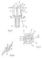
- Die Figur 1
- eine vergrößerte Ansicht eines Abschnitts eines wärmegedämmten Gehäuses eines Kühlschranks oder Gefrierschranks in einem Horizontalschnitt, mit einer Innenverkleidung, in der ein Verstärkungskörper angeordnet ist, der in einer becherförmigen, zur Wärmedämmung gerichteten Ausformung der Innenverkleidung befestigt ist;
- die Figur 2
- den Verstärkungskörper in einem von einer Seite aus gesehenen Querschnitt, in einer gegenüber der
Figur 1 vergrößerten Darstellung; - die Figur 3
- den Verstärkungskörper nach
Figur 2 in einer Aufsicht und - die Figur 4
- den Verstärkungskörper nach
Figur 2 in einem Schnitt längs der Schnittlinie IV-IV. - In der
Figur 1 wird ein Abschnitt einer Gehäusewand 10 gezeigt, die zu einem nicht dargestellten wärmegedämmten Gehäuse eines Kühlschranks oder Gefrierschranks gehört, welches eine Innenverkleidung 11 aufweist, eine durch Ausschäumung hergestellte wärmegedämmte Schicht 12 und eine Innenverkleidung 13, die den Innenraum des Kühlschranks oder Gefrierschranks bedeckt, wobei diese Innenverkleidung durch Warmumformung einer Kunststoffplatte in einem Tiefziehverfahren ohne Zerspanung hergestellt wurde. Diese Innenverkleidung ist mit einer becherfömigen Ausformung 14 ausgestattet, die zum Beispiel während des Tiefziehvorgangs der Kunststoffplatte hergestellt und mit einem kreisförmigen Querschnitt ausgestaltet wird, die sich zum wärmedämmenden Material 12 hin erstreckt und die in der Mitte des Becherbodens 15, der mit geschlossener Wand ausgestaltet ist, eine Zentrierhilfe 16 aufweist, die im Wesentlichen spitz zulaufend ausgestaltet ist. Die becherförmige Ausformung 14 ist an ihrer Mantelfläche 17 mit einem Vorsprung 18 ausgestattet, der zum wärmedämmenden Material 12 vorsteht. An die Mantelfläche wird ein Verstärkungskörper 20 gekoppelt, der sozusagen als Auflagestück dient. Dieser Verstärkungskörper ist im Wesentlichen in Form eines kreisförmigen Zylinders ausgestaltet und weist eine Aufnahmeabschnitt 21 in Form eines Hohlzapfens auf, dessen Aufnahmeöffnung 22 mit kreisförmigem Querschnitt die Mantelfläche 17 der becherfömigen Ausformung 14 übergreift. Die Aufnahmeöffnung 22 des in Form eines Hohlzapfens ausgeführten Aufnahmeabschnitts 21 ist von elastischen Zungen 23 umgeben, die als Wandabschnitte des Hohlzapfens dienen und die durch rechteckige, jeweils 90° zueinander versetzte Aussparungen 24 hergestellt werden, die sich entlang der Mantelfläche des Hohlzapfens in der umgebenden Wand des Hohlzapfens erstrecken und die einen kreisringsegmentförmigen Querschnitt aufweisen. Die elastischen Zungen 23 sind an ihrem freien, zum Inneren des Aufnahmeabschnitts gerichteten Ende mit einem Rand 19 versehen, der das Verschieben des Verstärkungskörpers in die Demontagerichtung verhindert. Die elastischen Zungen 23 sind an ihrem freien Ende, das als Zungenspitze dient, ebenfalls mit Anschlagelementen 25 versehen, die sich radial nach außen erstrecken, und die mit ihrer äußeren, nicht zum Aufnahmeabschnitt 21 gerichteten Anschlagfläche 26 im Montagezustand des Verstärkungskörpers 20 an der Außenseite der zur wärmedämmenden Schicht 12 gerichteten Innenverkleidung 13 anliegen, die ist und so die richtige Endposition bei dem Montagevorgang des Verstärkungskörpers 20 anzeigen. Die elastischen Zungen 23 sind mit ihren Zungenwurzeln an einem Befestigungsabschnitt 27 befestigt, der mit dem Aufnahmeabschnitt 21 verbunden wird (siehe hierzu dieFigur 2 ) und der im Wesentlichen in Form eines kreisförmigen Hohlzylinders ausgestaltet ist und an seiner Mantelfläche mit zwei Rippen 28 ausgestattet ist, die radial gegenüber der Mantelfläche vorstehen, wobei sich diese Rippen über die Mantelfläche des Aufnahmeabschnitts hervorstehen (siehe hierzu dieFigur 3 ). Der Befestigungsabschnitt 27 weist eine Blindbohrung 30 auf, die sich bis in die Nähe des freien Endes erstreckt und über die Längsmittelachse 29, wobei die Längsachse, die sich über den Mittelpunkt hin erstreckt ebenso wie die Längsachse die sich über den Mittelpunkt des Aufnahmeabschnitts 21 erstreckt mit der Längsmittelachse 29 des Befestigungsabschnitts 27 übereinstimmt. Die Blindbohrung 30 dient als Bohrung um den Kern für eine selbstschneidende, kreiszylinderförmige Schraube 31, die zur Befestigung des Bauteils 32 in der Innenverkleidung 13 in dem Kühlraum dient (siehe dieFigur 1 ). Das Bauteil 32 ist mit einem im Querschnitt kreisförmigen Kurzrohr zur Befestigung 33 versehen, wobei der Abschnitt des Kurzrohrs mit dem durch den Rücksprung verengten Querschnitt 34 für die Führung und die Stützung des Bauteils 32 während der Montage innerhalb der becherförmigen Ausformung 14 angeordnet ist und eine Durchgangsbohrung 35 aufweist, die an den Außendurchmesser der Befestigungsschraube 31 angepasst ist. Vor dem verengten Abschnitt des Kurzrohrs 34, der die Durchgangsbohrung 35 aufweist, ist ein Abschnitt des Kurzrohrs 36 mit einem im Vergleich zum anderen erweiterten Querschnitt angeordnet, der mit einer Aufnahmeöffnung 37 versehen ist, in der der Kopf der Befestigungsschraube 31 im Befestigungszustand des Bauteils 32 angeordnet ist und der an seinem vom Kurzrohrabschnitt 34 entfernt liegenden Ende mit einem Verschlussdeckel 38 geschlossen werden kann. Um die Stabilität zu erhöhen, ist das Kurzrohr zur Befestigung 33 an seiner Mantelfläche mit Stützrippen 39 versehen, die den erweiterten Abschnitt des Kurzrohrs 36 überspannen und sich bis zum verengten Abschnitt des Kurzrohrs 34 erstrecken, wobei diese Rippen jeweils den gleichen Winkelabstand von 90° zueinander aufweisen. - Der Verstärkungskörper 20 besteht im vorliegenden Ausführungsbeispiel aus einem einstückig hergestellten Kunststoffspritzgussteil, wobei die Blindbohrung 30 im Befestigungsabschnitt 27 bereits bei dem Spritzgussvorgang ausgebildet wird.
-
- 10
- Gehäuse
- 11
- Außenverkleidung
- 12
- Wärmedämmung
- 13
- Innenverkleidung
- 14
- Ausformung
- 15
- Becherboden
- 16
- Zentrierhilfe
- 17
- Mantelfläche
- 18
- Vorsprung
- 19
- Rand
- 20
- Verstärkungskörper
- 21
- Aufnahmeabschnitt
- 22
- Aufnahmeöffnung
- 23
- Elastische Zungen
- 24
- Ausnehmungen
- 25
- Anschlagelement
- 26
- Äußere Anschlagfläche
- 27
- Befestigungsabschnitt
- 28
- Rippen
- 29
- Längsachse
- 30
- Bohrung
- 31
- Befestigungsmittel
- 32
- Bauteil
- 33
- Kurzrohr zur Befestigung
- 34
- Verengter Kurzrohrabschnitt
- 35
- Durchgangsbohrung
- 36
- Erweiterter Kurzrohrabschnitt
- 37
- Aufnahmeöffnung
- 38
- Verschlussdeckel
- 39
- Stützrippen
Claims (13)
- Kühlschrank mit einem Gehäuse, umfassend
eine mit wärmedämmendem Material (12) umhüllte Innenverkleidung (13) aus Kunststoff, dieeine zum wärmedämmenden Material (12) gerichtete becherförmige Ausformung (14) aufweist; undeinen in das wärmedämmende Material eingebetteten Verstärkungskörper (20), derzumindest einen Aufnahmeabschnitt (21) aufweist, der in der Ausformung (14) befestigt werden kann, undeinen mit dem Aufnahmeabschnitt verbundenen Befestigungsabschnitt (27), der eine vorgefertigte Bohrung (30) aufweist, für die Einführung von Befestigungsmitteln (31) in Form von Schrauben, für das Halten von Bauteilen in der Innenverkleidung an der der Wärmedämmung (12) gegenüberliegenden Seite,dadurch gekennzeichnet, dass
die Ausformung (14) an ihrer Mantelfläche (17) zumindest einen Vorsprung (18) aufweist, in den der Aufnahmeabschnitt (21) formschlüssig einrastet. - Kühlschrank nach Anspruch 1, dadurch gekennzeichnet, dass die becherförmige Ausformung (14) am Becherboden (15) mit einer Zentrierhilfe (16) versehen ist und der mit der Mantelfläche (17) verbundene Aufnahmeabschnitt (21) in Form eines Hohlzapfens ausgebildet ist, dessen Mittelachse zumindest weitgehend mit der Mittelachse der vorgefertigten Bohrung (30) übereinstimmt sowie mit der Mittelachse der Zentrierhilfe (16).
- Kühlschrank nach Anspruch 2, dadurch gekennzeichnet, dass der Hohlzapfen aus elastischen Zungen (23) besteht, deren Zungenwurzeln am Befestigungsabschnitt (27) angeordnet sind.
- Kühlschrank nach Anspruch 3, dadurch gekennzeichnet, dass die elastischen Zungen (23) an ihrer Zungenspitze mit zumindest einem jeweils radial angeordneten Anschlagelement (25) ausgestattet sind, das an der Innenverkleidung (13) anliegt.
- Kühlschrank nach Anspruch 1, dadurch gekennzeichnet, dass der Befestigungsabschnitt (27) mit Rippen (28) versehen ist, die an dessen Mantelfläche radial zu dieser vorstehen und die sich in Richtung der Längsachse (29) erstrecken und formschlüssig mit dem wärmedämmenden Material (12) zusammenwirken können und den Verstärkungskörper (20) gegen Drehung sichern können.
- Kühlschrank nach Anspruch 5, dadurch gekennzeichnet, dass die Rippen (28) über die Mantelfläche des Aufnahmeabschnitts (21) vorstehen.
- Kühlschrank nach Anspruch 1, dadurch gekennzeichnet, dass die becherförmige Ausformung (14) und der Verstärkungskörper (20) einen kreisförmigen Querschnitt aufweisen.
- Kühlschrank nach einem der vorhergehenden Ansprüche, dadurch gekennzeichnet, dass die Mantelfläche (17) der Ausformung (14) kegelstumpfförmig ist.
- Kühlschrank nach einem der vorhergehenden Ansprüche, dadurch gekennzeichnet, dass der Vorsprung (18) sich zum wärmedämmenden Material (12) erstreckt und der Aufnahmeabschnitt einen Rand (19) hat, der zur Ausformung vorsteht und den Verstärkungskörper in der Ausformung einrasten lässt.
- Kühlschrank nach einem der Ansprüche 1 bis 8, dadurch gekennzeichnet, dass der Vorsprung (18) sich zum wärmedämmenden Material (12) erstreckt und der Aufnahmeabschnitt eine Aufnahme aufweist, um den Vorsprung (18) aufzunehmen.
- Kühlschrank nach einem der Ansprüche 3 bis 10, dadurch gekennzeichnet, dass sich die elastischen Zungen über den Vorsprung (18) hinweg erstrecken.
- Kühlschrank nach einem der vorhergehenden Ansprüche, dadurch gekennzeichnet, dass die Ausformung zumindest zwei gegenüberliegende Vorsprünge aufweist.
- Kühlschrank nach einem der Ansprüche 1 bis 12, dadurch gekennzeichnet, dass der Vorsprung den Umfang der Ausformung (14) umgibt.
Priority Applications (1)
| Application Number | Priority Date | Filing Date | Title |
|---|---|---|---|
| PL10194209T PL2333465T3 (pl) | 2009-12-14 | 2010-12-08 | Chłodziarka |
Applications Claiming Priority (1)
| Application Number | Priority Date | Filing Date | Title |
|---|---|---|---|
| ES200931163A ES2395215B1 (es) | 2009-12-14 | 2009-12-14 | Frigorifico |
Publications (3)
| Publication Number | Publication Date |
|---|---|
| EP2333465A2 true EP2333465A2 (de) | 2011-06-15 |
| EP2333465A3 EP2333465A3 (de) | 2016-01-06 |
| EP2333465B1 EP2333465B1 (de) | 2020-11-18 |
Family
ID=43821898
Family Applications (1)
| Application Number | Title | Priority Date | Filing Date |
|---|---|---|---|
| EP10194209.2A Active EP2333465B1 (de) | 2009-12-14 | 2010-12-08 | Kühlschrank |
Country Status (3)
| Country | Link |
|---|---|
| EP (1) | EP2333465B1 (de) |
| ES (1) | ES2395215B1 (de) |
| PL (1) | PL2333465T3 (de) |
Cited By (1)
| Publication number | Priority date | Publication date | Assignee | Title |
|---|---|---|---|---|
| CH721312A1 (de) * | 2023-11-22 | 2025-05-30 | V Zug Ag | Kühlgerät mit Montagevorrichtung zur Montage von Schubladen oder Türen |
Citations (1)
| Publication number | Priority date | Publication date | Assignee | Title |
|---|---|---|---|---|
| EP0935732B1 (de) | 1996-09-24 | 2001-03-07 | BSH Bosch und Siemens Hausgeräte GmbH | Kältegerät |
Family Cites Families (5)
| Publication number | Priority date | Publication date | Assignee | Title |
|---|---|---|---|---|
| KR19980067370U (ko) * | 1997-05-26 | 1998-12-05 | 배순훈 | 냉장고의 부품고정구 |
| ITMI20031281A1 (it) * | 2003-06-24 | 2004-12-25 | Whirlpool Co | Apparecchio refrigerante domestico con supporti amovibili dei ripiani. |
| KR101010793B1 (ko) * | 2004-02-11 | 2011-01-25 | 엘지전자 주식회사 | 냉장고 본체 및 그 제조방법 |
| DE102004062309A1 (de) * | 2004-12-23 | 2006-07-20 | BSH Bosch und Siemens Hausgeräte GmbH | Tiefgezogener Behälter und Verfahren zu dessen Herstellung |
| JP4304533B2 (ja) * | 2006-11-30 | 2009-07-29 | ダイキン工業株式会社 | キャップ、複層構造パネル、冷凍コンテナ及び複層構造パネルの製造方法 |
-
2009
- 2009-12-14 ES ES200931163A patent/ES2395215B1/es not_active Expired - Fee Related
-
2010
- 2010-12-08 EP EP10194209.2A patent/EP2333465B1/de active Active
- 2010-12-08 PL PL10194209T patent/PL2333465T3/pl unknown
Patent Citations (1)
| Publication number | Priority date | Publication date | Assignee | Title |
|---|---|---|---|---|
| EP0935732B1 (de) | 1996-09-24 | 2001-03-07 | BSH Bosch und Siemens Hausgeräte GmbH | Kältegerät |
Cited By (1)
| Publication number | Priority date | Publication date | Assignee | Title |
|---|---|---|---|---|
| CH721312A1 (de) * | 2023-11-22 | 2025-05-30 | V Zug Ag | Kühlgerät mit Montagevorrichtung zur Montage von Schubladen oder Türen |
Also Published As
| Publication number | Publication date |
|---|---|
| ES2395215A1 (es) | 2013-02-11 |
| EP2333465B1 (de) | 2020-11-18 |
| EP2333465A3 (de) | 2016-01-06 |
| PL2333465T3 (pl) | 2021-05-31 |
| ES2395215B1 (es) | 2013-12-26 |
Similar Documents
| Publication | Publication Date | Title |
|---|---|---|
| EP1525401B1 (de) | Kältegerät mit einem Innenbehälter und einem Befestigungselement zum Befestigen einer Teleskopschiene am Innenbehälter | |
| EP2636803B1 (de) | Unterputzkasten mit Putzdickenausgleich | |
| EP1728034B1 (de) | Verfahren zur befestigung von elementen an der innenverkleidung von kühl- und/oder gefriergeräten und verfahren zur herstellung einer solchen befestigungsanordnung | |
| EP2706185A1 (de) | Verfahren und Anordnung zum Befestigen eines Pfostens an einer Rahmenleiste eines Fensters oder einer Türe mittels eines Pfostenverbinders | |
| DE2640587A1 (de) | Befestigungsanordnung fuer an der innenwand eines kuehlschranks zu befestigende teile | |
| EP1831624A1 (de) | Tiefgezogener behälter und verfahren zu dessen herstellung | |
| DE3403053A1 (de) | Schalterdose | |
| EP0935732B1 (de) | Kältegerät | |
| EP1103771B1 (de) | Kältegerätetür | |
| EP2697582B1 (de) | Einbau-kältegerät mit einem beschlagsbauteil | |
| EP3494266B1 (de) | Befestigungseinrichtung | |
| EP2333465B1 (de) | Kühlschrank | |
| DE102004045475A1 (de) | Bauteil zur Montage an einer hinterschäumten Wand und damit ausgestattetes Kältegerät | |
| EP3884229B1 (de) | Kältegerät mit leitungsdurchführung | |
| EP3452733A1 (de) | Verlängerungsadapter einer steckkupplung sowie dazugehöriges herstellungs- und montageverfahren | |
| EP0153643B1 (de) | Spreizdübel | |
| DE2907049C2 (de) | Elektrische Hohlwanddose | |
| DE202018004467U1 (de) | Kältegerät mit Einbauteil | |
| DE102014203619A1 (de) | Haushaltsgerät | |
| DE102013103172A1 (de) | Vorrichtung, Bauanordnung und Verfahren zum Festlegen eines Gerüsts an einer Fassade sowie Verfahren zur Herstellung der Vorrichtung | |
| DE102014206948A1 (de) | Haushaltskältegerät | |
| DE102005051172A1 (de) | Befestigungselement für die mechanische Befestigung von Dämm- und Dichtungsmaterialien auf Flachdächern | |
| WO2010118937A2 (de) | Kältegerät | |
| DE102020205380A1 (de) | Möbel-Rückwandverbinder | |
| EP2417368B1 (de) | Spreizniete |
Legal Events
| Date | Code | Title | Description |
|---|---|---|---|
| PUAI | Public reference made under article 153(3) epc to a published international application that has entered the european phase |
Free format text: ORIGINAL CODE: 0009012 |
|
| AK | Designated contracting states |
Kind code of ref document: A2 Designated state(s): AL AT BE BG CH CY CZ DE DK EE ES FI FR GB GR HR HU IE IS IT LI LT LU LV MC MK MT NL NO PL PT RO RS SE SI SK SM TR |
|
| AX | Request for extension of the european patent |
Extension state: BA ME |
|
| RAP1 | Party data changed (applicant data changed or rights of an application transferred) |
Owner name: BSH HAUSGERAETE GMBH |
|
| PUAL | Search report despatched |
Free format text: ORIGINAL CODE: 0009013 |
|
| AK | Designated contracting states |
Kind code of ref document: A3 Designated state(s): AL AT BE BG CH CY CZ DE DK EE ES FI FR GB GR HR HU IE IS IT LI LT LU LV MC MK MT NL NO PL PT RO RS SE SI SK SM TR |
|
| AX | Request for extension of the european patent |
Extension state: BA ME |
|
| RIC1 | Information provided on ipc code assigned before grant |
Ipc: F25D 23/06 20060101AFI20151202BHEP |
|
| 17P | Request for examination filed |
Effective date: 20160706 |
|
| RBV | Designated contracting states (corrected) |
Designated state(s): AL AT BE BG CH CY CZ DE DK EE ES FI FR GB GR HR HU IE IS IT LI LT LU LV MC MK MT NL NO PL PT RO RS SE SI SK SM TR |
|
| GRAP | Despatch of communication of intention to grant a patent |
Free format text: ORIGINAL CODE: EPIDOSNIGR1 |
|
| STAA | Information on the status of an ep patent application or granted ep patent |
Free format text: STATUS: GRANT OF PATENT IS INTENDED |
|
| INTG | Intention to grant announced |
Effective date: 20200619 |
|
| GRAS | Grant fee paid |
Free format text: ORIGINAL CODE: EPIDOSNIGR3 |
|
| GRAA | (expected) grant |
Free format text: ORIGINAL CODE: 0009210 |
|
| STAA | Information on the status of an ep patent application or granted ep patent |
Free format text: STATUS: THE PATENT HAS BEEN GRANTED |
|
| AK | Designated contracting states |
Kind code of ref document: B1 Designated state(s): AL AT BE BG CH CY CZ DE DK EE ES FI FR GB GR HR HU IE IS IT LI LT LU LV MC MK MT NL NO PL PT RO RS SE SI SK SM TR |
|
| REG | Reference to a national code |
Ref country code: GB Ref legal event code: FG4D Free format text: NOT ENGLISH |
|
| REG | Reference to a national code |
Ref country code: CH Ref legal event code: EP |
|
| REG | Reference to a national code |
Ref country code: DE Ref legal event code: R096 Ref document number: 502010016800 Country of ref document: DE |
|
| REG | Reference to a national code |
Ref country code: IE Ref legal event code: FG4D Free format text: LANGUAGE OF EP DOCUMENT: GERMAN |
|
| REG | Reference to a national code |
Ref country code: AT Ref legal event code: REF Ref document number: 1336218 Country of ref document: AT Kind code of ref document: T Effective date: 20201215 |
|
| REG | Reference to a national code |
Ref country code: NL Ref legal event code: MP Effective date: 20201118 |
|
| PG25 | Lapsed in a contracting state [announced via postgrant information from national office to epo] |
Ref country code: FI Free format text: LAPSE BECAUSE OF FAILURE TO SUBMIT A TRANSLATION OF THE DESCRIPTION OR TO PAY THE FEE WITHIN THE PRESCRIBED TIME-LIMIT Effective date: 20201118 Ref country code: RS Free format text: LAPSE BECAUSE OF FAILURE TO SUBMIT A TRANSLATION OF THE DESCRIPTION OR TO PAY THE FEE WITHIN THE PRESCRIBED TIME-LIMIT Effective date: 20201118 Ref country code: PT Free format text: LAPSE BECAUSE OF FAILURE TO SUBMIT A TRANSLATION OF THE DESCRIPTION OR TO PAY THE FEE WITHIN THE PRESCRIBED TIME-LIMIT Effective date: 20210318 Ref country code: NO Free format text: LAPSE BECAUSE OF FAILURE TO SUBMIT A TRANSLATION OF THE DESCRIPTION OR TO PAY THE FEE WITHIN THE PRESCRIBED TIME-LIMIT Effective date: 20210218 Ref country code: GR Free format text: LAPSE BECAUSE OF FAILURE TO SUBMIT A TRANSLATION OF THE DESCRIPTION OR TO PAY THE FEE WITHIN THE PRESCRIBED TIME-LIMIT Effective date: 20210219 |
|
| PG25 | Lapsed in a contracting state [announced via postgrant information from national office to epo] |
Ref country code: BG Free format text: LAPSE BECAUSE OF FAILURE TO SUBMIT A TRANSLATION OF THE DESCRIPTION OR TO PAY THE FEE WITHIN THE PRESCRIBED TIME-LIMIT Effective date: 20210218 Ref country code: IS Free format text: LAPSE BECAUSE OF FAILURE TO SUBMIT A TRANSLATION OF THE DESCRIPTION OR TO PAY THE FEE WITHIN THE PRESCRIBED TIME-LIMIT Effective date: 20210318 Ref country code: LV Free format text: LAPSE BECAUSE OF FAILURE TO SUBMIT A TRANSLATION OF THE DESCRIPTION OR TO PAY THE FEE WITHIN THE PRESCRIBED TIME-LIMIT Effective date: 20201118 Ref country code: SE Free format text: LAPSE BECAUSE OF FAILURE TO SUBMIT A TRANSLATION OF THE DESCRIPTION OR TO PAY THE FEE WITHIN THE PRESCRIBED TIME-LIMIT Effective date: 20201118 |
|
| REG | Reference to a national code |
Ref country code: LT Ref legal event code: MG9D |
|
| PG25 | Lapsed in a contracting state [announced via postgrant information from national office to epo] |
Ref country code: HR Free format text: LAPSE BECAUSE OF FAILURE TO SUBMIT A TRANSLATION OF THE DESCRIPTION OR TO PAY THE FEE WITHIN THE PRESCRIBED TIME-LIMIT Effective date: 20201118 |
|
| PG25 | Lapsed in a contracting state [announced via postgrant information from national office to epo] |
Ref country code: SM Free format text: LAPSE BECAUSE OF FAILURE TO SUBMIT A TRANSLATION OF THE DESCRIPTION OR TO PAY THE FEE WITHIN THE PRESCRIBED TIME-LIMIT Effective date: 20201118 Ref country code: RO Free format text: LAPSE BECAUSE OF FAILURE TO SUBMIT A TRANSLATION OF THE DESCRIPTION OR TO PAY THE FEE WITHIN THE PRESCRIBED TIME-LIMIT Effective date: 20201118 Ref country code: SK Free format text: LAPSE BECAUSE OF FAILURE TO SUBMIT A TRANSLATION OF THE DESCRIPTION OR TO PAY THE FEE WITHIN THE PRESCRIBED TIME-LIMIT Effective date: 20201118 Ref country code: EE Free format text: LAPSE BECAUSE OF FAILURE TO SUBMIT A TRANSLATION OF THE DESCRIPTION OR TO PAY THE FEE WITHIN THE PRESCRIBED TIME-LIMIT Effective date: 20201118 Ref country code: CZ Free format text: LAPSE BECAUSE OF FAILURE TO SUBMIT A TRANSLATION OF THE DESCRIPTION OR TO PAY THE FEE WITHIN THE PRESCRIBED TIME-LIMIT Effective date: 20201118 Ref country code: LT Free format text: LAPSE BECAUSE OF FAILURE TO SUBMIT A TRANSLATION OF THE DESCRIPTION OR TO PAY THE FEE WITHIN THE PRESCRIBED TIME-LIMIT Effective date: 20201118 |
|
| REG | Reference to a national code |
Ref country code: CH Ref legal event code: PL |
|
| REG | Reference to a national code |
Ref country code: DE Ref legal event code: R097 Ref document number: 502010016800 Country of ref document: DE |
|
| PG25 | Lapsed in a contracting state [announced via postgrant information from national office to epo] |
Ref country code: DK Free format text: LAPSE BECAUSE OF FAILURE TO SUBMIT A TRANSLATION OF THE DESCRIPTION OR TO PAY THE FEE WITHIN THE PRESCRIBED TIME-LIMIT Effective date: 20201118 Ref country code: MC Free format text: LAPSE BECAUSE OF FAILURE TO SUBMIT A TRANSLATION OF THE DESCRIPTION OR TO PAY THE FEE WITHIN THE PRESCRIBED TIME-LIMIT Effective date: 20201118 |
|
| REG | Reference to a national code |
Ref country code: BE Ref legal event code: MM Effective date: 20201231 |
|
| PLBE | No opposition filed within time limit |
Free format text: ORIGINAL CODE: 0009261 |
|
| STAA | Information on the status of an ep patent application or granted ep patent |
Free format text: STATUS: NO OPPOSITION FILED WITHIN TIME LIMIT |
|
| 26N | No opposition filed |
Effective date: 20210819 |
|
| GBPC | Gb: european patent ceased through non-payment of renewal fee |
Effective date: 20210218 |
|
| PG25 | Lapsed in a contracting state [announced via postgrant information from national office to epo] |
Ref country code: NL Free format text: LAPSE BECAUSE OF FAILURE TO SUBMIT A TRANSLATION OF THE DESCRIPTION OR TO PAY THE FEE WITHIN THE PRESCRIBED TIME-LIMIT Effective date: 20201118 Ref country code: LU Free format text: LAPSE BECAUSE OF NON-PAYMENT OF DUE FEES Effective date: 20201208 Ref country code: FR Free format text: LAPSE BECAUSE OF NON-PAYMENT OF DUE FEES Effective date: 20210118 Ref country code: IE Free format text: LAPSE BECAUSE OF NON-PAYMENT OF DUE FEES Effective date: 20201208 Ref country code: AL Free format text: LAPSE BECAUSE OF FAILURE TO SUBMIT A TRANSLATION OF THE DESCRIPTION OR TO PAY THE FEE WITHIN THE PRESCRIBED TIME-LIMIT Effective date: 20201118 |
|
| PG25 | Lapsed in a contracting state [announced via postgrant information from national office to epo] |
Ref country code: CH Free format text: LAPSE BECAUSE OF NON-PAYMENT OF DUE FEES Effective date: 20201231 Ref country code: ES Free format text: LAPSE BECAUSE OF FAILURE TO SUBMIT A TRANSLATION OF THE DESCRIPTION OR TO PAY THE FEE WITHIN THE PRESCRIBED TIME-LIMIT Effective date: 20201118 Ref country code: LI Free format text: LAPSE BECAUSE OF NON-PAYMENT OF DUE FEES Effective date: 20201231 Ref country code: SI Free format text: LAPSE BECAUSE OF FAILURE TO SUBMIT A TRANSLATION OF THE DESCRIPTION OR TO PAY THE FEE WITHIN THE PRESCRIBED TIME-LIMIT Effective date: 20201118 |
|
| PG25 | Lapsed in a contracting state [announced via postgrant information from national office to epo] |
Ref country code: GB Free format text: LAPSE BECAUSE OF NON-PAYMENT OF DUE FEES Effective date: 20210218 |
|
| REG | Reference to a national code |
Ref country code: AT Ref legal event code: MM01 Ref document number: 1336218 Country of ref document: AT Kind code of ref document: T Effective date: 20201208 |
|
| PG25 | Lapsed in a contracting state [announced via postgrant information from national office to epo] |
Ref country code: AT Free format text: LAPSE BECAUSE OF NON-PAYMENT OF DUE FEES Effective date: 20201208 |
|
| PG25 | Lapsed in a contracting state [announced via postgrant information from national office to epo] |
Ref country code: IS Free format text: LAPSE BECAUSE OF FAILURE TO SUBMIT A TRANSLATION OF THE DESCRIPTION OR TO PAY THE FEE WITHIN THE PRESCRIBED TIME-LIMIT Effective date: 20210318 Ref country code: MT Free format text: LAPSE BECAUSE OF FAILURE TO SUBMIT A TRANSLATION OF THE DESCRIPTION OR TO PAY THE FEE WITHIN THE PRESCRIBED TIME-LIMIT Effective date: 20201118 Ref country code: CY Free format text: LAPSE BECAUSE OF FAILURE TO SUBMIT A TRANSLATION OF THE DESCRIPTION OR TO PAY THE FEE WITHIN THE PRESCRIBED TIME-LIMIT Effective date: 20201118 |
|
| PG25 | Lapsed in a contracting state [announced via postgrant information from national office to epo] |
Ref country code: MK Free format text: LAPSE BECAUSE OF FAILURE TO SUBMIT A TRANSLATION OF THE DESCRIPTION OR TO PAY THE FEE WITHIN THE PRESCRIBED TIME-LIMIT Effective date: 20201118 |
|
| PG25 | Lapsed in a contracting state [announced via postgrant information from national office to epo] |
Ref country code: BE Free format text: LAPSE BECAUSE OF NON-PAYMENT OF DUE FEES Effective date: 20201231 |
|
| REG | Reference to a national code |
Ref country code: DE Ref legal event code: R084 Ref document number: 502010016800 Country of ref document: DE |
|
| PGFP | Annual fee paid to national office [announced via postgrant information from national office to epo] |
Ref country code: IT Payment date: 20231229 Year of fee payment: 14 |
|
| PGFP | Annual fee paid to national office [announced via postgrant information from national office to epo] |
Ref country code: DE Payment date: 20240703 Year of fee payment: 15 |
|
| PG25 | Lapsed in a contracting state [announced via postgrant information from national office to epo] |
Ref country code: IT Free format text: LAPSE BECAUSE OF NON-PAYMENT OF DUE FEES Effective date: 20241208 |
|
| PGFP | Annual fee paid to national office [announced via postgrant information from national office to epo] |
Ref country code: TR Payment date: 20251202 Year of fee payment: 16 |
|
| PGFP | Annual fee paid to national office [announced via postgrant information from national office to epo] |
Ref country code: PL Payment date: 20251128 Year of fee payment: 16 |