EP2333344A2 - Vacuum pump - Google Patents
Vacuum pump Download PDFInfo
- Publication number
- EP2333344A2 EP2333344A2 EP10191203A EP10191203A EP2333344A2 EP 2333344 A2 EP2333344 A2 EP 2333344A2 EP 10191203 A EP10191203 A EP 10191203A EP 10191203 A EP10191203 A EP 10191203A EP 2333344 A2 EP2333344 A2 EP 2333344A2
- Authority
- EP
- European Patent Office
- Prior art keywords
- rotor shaft
- vacuum pump
- suction
- rotor
- pump according
- Prior art date
- Legal status (The legal status is an assumption and is not a legal conclusion. Google has not performed a legal analysis and makes no representation as to the accuracy of the status listed.)
- Withdrawn
Links
Images
Classifications
-
- F—MECHANICAL ENGINEERING; LIGHTING; HEATING; WEAPONS; BLASTING
- F04—POSITIVE - DISPLACEMENT MACHINES FOR LIQUIDS; PUMPS FOR LIQUIDS OR ELASTIC FLUIDS
- F04D—NON-POSITIVE-DISPLACEMENT PUMPS
- F04D19/00—Axial-flow pumps
- F04D19/02—Multi-stage pumps
- F04D19/04—Multi-stage pumps specially adapted to the production of a high vacuum, e.g. molecular pumps
- F04D19/042—Turbomolecular vacuum pumps
-
- F—MECHANICAL ENGINEERING; LIGHTING; HEATING; WEAPONS; BLASTING
- F04—POSITIVE - DISPLACEMENT MACHINES FOR LIQUIDS; PUMPS FOR LIQUIDS OR ELASTIC FLUIDS
- F04D—NON-POSITIVE-DISPLACEMENT PUMPS
- F04D19/00—Axial-flow pumps
- F04D19/02—Multi-stage pumps
- F04D19/04—Multi-stage pumps specially adapted to the production of a high vacuum, e.g. molecular pumps
- F04D19/048—Multi-stage pumps specially adapted to the production of a high vacuum, e.g. molecular pumps comprising magnetic bearings
-
- F—MECHANICAL ENGINEERING; LIGHTING; HEATING; WEAPONS; BLASTING
- F04—POSITIVE - DISPLACEMENT MACHINES FOR LIQUIDS; PUMPS FOR LIQUIDS OR ELASTIC FLUIDS
- F04D—NON-POSITIVE-DISPLACEMENT PUMPS
- F04D29/00—Details, component parts, or accessories
- F04D29/05—Shafts or bearings, or assemblies thereof, specially adapted for elastic fluid pumps
- F04D29/056—Bearings
- F04D29/0563—Bearings cartridges
-
- F—MECHANICAL ENGINEERING; LIGHTING; HEATING; WEAPONS; BLASTING
- F04—POSITIVE - DISPLACEMENT MACHINES FOR LIQUIDS; PUMPS FOR LIQUIDS OR ELASTIC FLUIDS
- F04D—NON-POSITIVE-DISPLACEMENT PUMPS
- F04D29/00—Details, component parts, or accessories
- F04D29/05—Shafts or bearings, or assemblies thereof, specially adapted for elastic fluid pumps
- F04D29/056—Bearings
- F04D29/058—Bearings magnetic; electromagnetic
-
- F—MECHANICAL ENGINEERING; LIGHTING; HEATING; WEAPONS; BLASTING
- F04—POSITIVE - DISPLACEMENT MACHINES FOR LIQUIDS; PUMPS FOR LIQUIDS OR ELASTIC FLUIDS
- F04D—NON-POSITIVE-DISPLACEMENT PUMPS
- F04D29/00—Details, component parts, or accessories
- F04D29/05—Shafts or bearings, or assemblies thereof, specially adapted for elastic fluid pumps
- F04D29/056—Bearings
- F04D29/059—Roller bearings
-
- F—MECHANICAL ENGINEERING; LIGHTING; HEATING; WEAPONS; BLASTING
- F16—ENGINEERING ELEMENTS AND UNITS; GENERAL MEASURES FOR PRODUCING AND MAINTAINING EFFECTIVE FUNCTIONING OF MACHINES OR INSTALLATIONS; THERMAL INSULATION IN GENERAL
- F16C—SHAFTS; FLEXIBLE SHAFTS; ELEMENTS OR CRANKSHAFT MECHANISMS; ROTARY BODIES OTHER THAN GEARING ELEMENTS; BEARINGS
- F16C32/00—Bearings not otherwise provided for
- F16C32/04—Bearings not otherwise provided for using magnetic or electric supporting means
- F16C32/0402—Bearings not otherwise provided for using magnetic or electric supporting means combined with other supporting means, e.g. hybrid bearings with both magnetic and fluid supporting means
-
- F—MECHANICAL ENGINEERING; LIGHTING; HEATING; WEAPONS; BLASTING
- F16—ENGINEERING ELEMENTS AND UNITS; GENERAL MEASURES FOR PRODUCING AND MAINTAINING EFFECTIVE FUNCTIONING OF MACHINES OR INSTALLATIONS; THERMAL INSULATION IN GENERAL
- F16C—SHAFTS; FLEXIBLE SHAFTS; ELEMENTS OR CRANKSHAFT MECHANISMS; ROTARY BODIES OTHER THAN GEARING ELEMENTS; BEARINGS
- F16C2360/00—Engines or pumps
- F16C2360/44—Centrifugal pumps
- F16C2360/45—Turbo-molecular pumps
Definitions
- the invention relates to a vacuum pump, in particular a turbomolecular pump or multi-inlet turbomolecular pump.
- Turbomolecular pumps have a rotor device having at least one rotor with a plurality of rotor disks. Between the rotor disks stator disks held by stator rings are arranged. The rotor device is arranged on a rapidly rotating rotor shaft. Turbomolecular pumps have a suction-side inlet and a discharge-side outlet. At the suction inlet end pressures of possibly less than 1 ⁇ 10 -10 mbar can be achieved. Additional backing pumps are often connected to the pressure-side pump connection.
- Multi-inlet pumps have at least one intermediate inlet in addition to a suction-side main inlet.
- the rotor device of a multi-inlet pump has two, for example designed as turbomolecular stages, pumping stages, wherein the intermediate inlet is arranged between the two pumping stages.
- the Subordinated turbomolecular stages is often another pumping stage, such as a Holweck stage, provided.
- Multi-inlet pumps can achieve different pressure levels at the main and at least one intermediate inlet.
- the bearing of the rotor shaft of particularly fast-rotating vacuum pumps can be on the pressure side, i. In areas where no low pressures prevail, take place via electromagnetic bearings.
- electromagnetic bearings are used in known vacuum pumps in pressure ranges up to 120 mbar.
- passive magnetic bearings it is known to support the rotor shaft in the high vacuum range by passive magnetic bearings.
- turbomolecular pumps and in particular in multi-inlet pumps, it is desirable to increase the total pumping power and possibly to increase the intermediate inlets to provide a rotor shaft as long as possible.
- the length of the rotor shaft is limited due to machine dynamic limits.
- the maximum rotor lengths are currently about 170 mm with a rotor diameter of about 130 mm and a shaft diameter of about 8 mm.
- the object of the invention is to provide a vacuum pump, in particular a turbomolecular pump or a multi-inlet pump, with extended rotor shaft.
- the vacuum pump according to the invention has a rotor shaft which carries a rotor device, wherein the rotor device may optionally have a plurality of rotors or other suction or pumping devices.
- the rotor shaft is over Usually two bearing assemblies, a pressure-side and a suction-side bearing assembly stored.
- the suction-side bearing arrangement is an electromagnetic bearing for the radial mounting of the rotor shaft. With the help of the electromagnetic bearing thus takes place exclusively a biaxial bearing of the rotor shaft. A storage in the axial direction is preferably carried out here by the electromagnetic bearing.
- the pressure-side bearing assembly designed as a rolling bearing, in particular as a ball bearing.
- a roller bearing is used, or the rolling bearing arranged such that both an axial and a radial, that is, a three-axis bearing of the shaft takes place through the rolling bearing. Due to the bearing arrangement according to the invention, it is possible to provide a long rotor shaft, which corresponds to the high quality requirements, in particular to the life of turbomolecular pumps or multi-inlet pumps. This has the particular advantage that a shaft which is mounted on the shaft ends, between the bearings can be stiffened arbitrarily, without having to take into consideration for joint diameter for suitable bearing consideration. Due to the high rigidity of the shaft, the bending-critical natural frequencies are shifted far away from the nominal frequency of the pump. Since bearings operated close to the natural frequencies of the shaft are subjected to additional dynamic loads, operation far away from the natural frequencies has a positive influence on the service life of the bearings.
- the provision of an electromagnetic bearing on the suction side has the advantage that contamination of the process gases is avoided even at low pressures.
- a degassing of the lubricant and thus a contamination of the process gases would take place due to the low pressures.
- the suction-side bearing assembly is used exclusively for radial mounting.
- the rotor shaft is thus preferably not axially mounted on the suction side.
- the suction side provided electromagnetic bearing can preferably be used for biasing the pressure side of the intended rolling bearing. This can be achieved by a slight axial displacement of the components of the electromagnetic bearing.
- To carry out the bias of the rolling bearing by means of the suction-side electromagnetic bearing has the advantage that no separate biasing means, that is, no separate component must be provided. Rather, the biasing device is realized by the electromagnetic bearing.
- the electric motor is preferably arranged such that it acts directly on the rotor shaft and thus the rotor shaft is driven directly by the electric motor.
- a bias voltage can be generated. This has according to the generation of the bias voltage by the electromagnetic bearing, the advantage that no additional component is required.
- a separate biasing device for example, a magnet which is preferably arranged in the region of the roller bearing may be provided as the pretensioning device. This is in particular a permanent magnet, which thus applies a clearly defined preload force.
- the suction-side bearing assembly and / or the pressure-side bearing arrangement is arranged in each case at one end of the rotor shaft.
- the rotor shaft is therefore not projecting on both sides, in particular in the region of the high vacuum, no projection of the rotor shaft.
- This is possible due to the bearing arrangement and design according to the invention.
- lower forces and moments occur in the bearings of the rotor shaft of a turbomolecular pump or a multi-inlet pump.
- This makes it possible, in particular in the region of the electromagnetic bearing a Provide rotor shaft with a smaller diameter. This has the particular advantage that a smaller fishing camp can be provided. This leads to cost savings.
- all rotor devices are thus arranged between the bearings.
- the rotor devices cover the bearings in the axial direction at best, however, are always connected between the bearing assemblies with the rotor shaft.
- rotor shafts can be realized with a length of more than 200 mm at a rotor diameter of about 130 mm for turbomolecular pumps and multi-inlet pumps.
- the electromagnetic bearing of the suction side bearing assembly is preferably arranged in a cartridge. In this way it can be achieved that, in particular, the coil of the bearing is arranged in a region with a higher pressure than the suction pressure prevailing minimum pressure.
- the suction-side bearing arrangement can be arranged in a high-vacuum region and thus exposed to low pressures. Furthermore, the suction-side bearing arrangement according to the invention is an electromagnetic bearing. High vacuum is understood to mean a pressure of less than 10 -3 mbar, in particular less than 10 -5 mbar and particularly preferably less than 10 -10 mbar.
- the electromagnetic bearing when arranging the electromagnetic bearing in the range of very low pressures, as they occur on the suction side, ie in the inlet region of a turbomolecular pump, is carried out in a particularly preferred embodiment arranging the coil of the electromagnetic bearing in a pressure-sealed recess. Due to the arrangement of the coil in a pressure-sealed recess ensures that the coil itself is not located directly in the high vacuum region. This avoids the disadvantage that due to the numerous cavities within the Coil due to the prolonged outgassing reaching the final pressure is not possible or difficult.
- the inventive provision of an electromagnetic bearing in the high vacuum range it is possible to store the rotor shaft in the end regions.
- the recess in a housing element, i. preferably in a stationary element connected to the housing.
- An opening of the recess is in this case preferably directed in the direction of the rotor shaft.
- the recess is annular and surrounds the rotor shaft completely.
- the electrical supply lines can preferably be fed through the housing into the recess and not from the side of the opening provided in the direction of the rotor shaft opening of the recess.
- the opening of the recess according to the invention is sealed by a particular tubular closing element.
- the preferably inwardly facing in the direction of the rotor shaft opening can thus be closed in a simple manner by a tubular closure element.
- annular cylindrical recess corresponds to the opening of the recess of the inner circumferential surface of the annular cylinder.
- the closing element may preferably be sealingly connected to the housing element via sealing elements, such as O-rings.
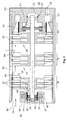
- a multi-inlet pump as shown schematically in Fig. 1 is shown, has a rotor shaft 12 in a housing 10.
- the rotor shaft 12 carries a plurality of rotor devices 14.
- Each rotor device 14 has a plurality of rotor disks 16.
- stator 18 Between the rotor discs 16 stator 18 are arranged.
- a suction side 22 of the pump represents the high-vacuum connection, so that medium is sucked in the direction of an arrow 24.
- An outlet 26 of the turbomolecular pump or the pressure side 28 is usually connected to a pre-vacuum pump.
- a suction-side bearing arrangement 30 has an electromagnetic bearing.
- This has a coil 32 of an electromagnet and a bearing element 34 which rotates fixedly with the rotor shaft 12 and which are, for example, so-called electrical sheets.
- the coil 32 is formed in a, formed in the illustrated embodiment as a circular-ring cylinder, recess 38 of a housing member 40.
- the recess 38 surrounds the rotor shaft 12 in an end region.
- the recess 38 is closed by a tubular closing element 42 and sealing elements 44, which are in particular O-rings, so that the recess 38 is pressure-encapsulated. Within the recess 38 thus does not prevail in the region 22 prevailing high vacuum. This avoids that present in the coil numerous cavities complicate the achievement of the final pressure or even prevent.
- the suction-side bearing arrangement 30 illustrated has a mechanical catch bearing 20 designed, for example, as a ball bearing.
- the fishing camp 20 is disposed in the housing member 40 and has a small distance to a pin of the shaft 12.
- the fishing camp 20 essentially serves to ensure emergency running properties in the event of a failure of the electromagnetic bearing.
- the housing member 40 is cup-shaped and surrounds a suction-side end portion of the rotor shaft 12th
- the provided on the pressure side 28 bearing assembly 56 is designed as a rolling bearing, in particular as a ball bearing 58.
- the ball bearing 58 is formed or connected to a housing cover 60, that both axial and radial forces can be absorbed by the ball bearing 58.
- the suction side bearing assembly 30 thus serves according to the invention exclusively for the radial support of the shaft 12, wherein the pressure-side bearing assembly 56 serves for the axial and radial support of the shaft 12.
- an axial prestressing of the bearing 58 takes place. This can be done with the aid of the designed as an electromagnetic bearing suction side bearing assembly 30. A corresponding bias can already be done by a small axial offset between the coil 32 and the bearing element 34. It is also possible to realize an axial prestressing of the bearing arrangement 56 with the aid of an electric motor 62.
- the motor 62 which is supported by the housing cover 60 in the illustrated embodiment, has, for example, a permanent magnet 64 connected to the rotor shaft 12 and a coil arrangement 66. By an axial offset between the permanent magnet 64 and the coil assembly 66 can also be a bias of the ball bearing 58 done.
- the rotor shaft 12 mounted in its two end regions via the bearing arrangements 30 and 56 has a plurality of rotor devices for forming a plurality of compressor stages 76, 78, 80 in the case of a multi-inlet pump.
- the first two compressor stages 76, 78 are turbomolecular pumps, each having a rotor 14 with rotor disks 16. Between the rotor discs 16 stator 18 are arranged. The two rotors 14 are arranged at a distance from one another on the rotor shaft 12. Between the two rotors 14, the housing 10 has an inlet opening 82, which is the intermediate inlet.
- the illustrated multi-inlet pump has a main inlet 84, which is the high vacuum port. Through the main inlet, the sucked gas flows in the direction of the arrow 24. In the region of the intermediate inlet 82 is additionally drawn, as shown by the arrow 86, through the intermediate inlet medium and in Fig. 1 promoted to the right.
- the third compressor stage then conveys the medium, as shown by an arrow 88, in the direction of the pressure side 28 and the outlet 26.
- a pre-vacuum pump To the outlet 26 is usually connected a pre-vacuum pump.
- the third compression stage 80 may include, for example, a Holweck stage or the like.
- suction side bearing assembly 30 Due to the inventive design of the suction side bearing assembly 30, it is possible to provide the two bearing assemblies 56, 30 at the shaft ends, so that a maximum bearing distance can be realized.
Abstract
Description
Die Erfindung betrifft eine Vakuumpumpe, insbesondere eine Turbomolekularpumpe oder Multi-Inlet-Turbomolekularpumpe.The invention relates to a vacuum pump, in particular a turbomolecular pump or multi-inlet turbomolecular pump.
Turbomolekularpumpen weisen eine mindestens einen Rotor mit mehreren Rotorscheiben aufweisenden Rotoreinrichtung auf. Zwischen den Rotorscheiben sind von Statorringen gehaltenen Statorscheiben angeordnet. Die Rotoreinrichtung ist auf einer schnell rotierenden Rotorwelle angeordnet. Turbomolekularpumpen weisen einen saugseitigen Einlass sowie einen druckseitigen Auslass auf. Am saugseitigen Einlass können Enddrücke von ggf. weniger als 1 · 10-10 mbar erzielt werden. An dem druckseitigen Pumpenanschluss sind häufig zusätzliche Vorvakuumpumpen angeschlossen.Turbomolecular pumps have a rotor device having at least one rotor with a plurality of rotor disks. Between the rotor disks stator disks held by stator rings are arranged. The rotor device is arranged on a rapidly rotating rotor shaft. Turbomolecular pumps have a suction-side inlet and a discharge-side outlet. At the suction inlet end pressures of possibly less than 1 × 10 -10 mbar can be achieved. Additional backing pumps are often connected to the pressure-side pump connection.
Multi-Inlet-Pumpen weisen zusätzlich zu einem saugseitigen Haupteinlass mindestens einen Zwischeneinlass auf. Üblicherweise weist die Rotoreinrichtung einer Multi-Inlet-Pumpe zwei, beispielsweise als Turbomolekularstufen ausgebildete, Pumpstufen auf, wobei zwischen den beiden Pumpstufen der Zwischeneinlass angeordnet ist. In Förderrichtung den Turbomolekularstufen nachgeordnet ist häufig eine weitere Pumpstufe, wie eine Holweck-Stufe, vorgesehen. Durch Multi-Inlet-Pumpen können unterschiedliche Druckniveaus am Haupt- und an dem mindestens einen Zwischeneinlass erzielt werden.Multi-inlet pumps have at least one intermediate inlet in addition to a suction-side main inlet. Usually, the rotor device of a multi-inlet pump has two, for example designed as turbomolecular stages, pumping stages, wherein the intermediate inlet is arranged between the two pumping stages. In the conveying direction the Subordinated turbomolecular stages is often another pumping stage, such as a Holweck stage, provided. Multi-inlet pumps can achieve different pressure levels at the main and at least one intermediate inlet.
Die Lagerung der Rotorwelle von insbesondere schnell drehenden Vakuumpumpen, wie Turbomolekularpumpen und Multi-Inlet-Pumpen, kann druckseitig, d.h. in Bereichen, in denen keine niedrigen Drücke herrschen, über elektromagnetische Lager erfolgen. Hierbei werden elektromagnetische Lager bei bekannten Vakuumpumpen in Druckbereichen bis zu 120 mbar eingesetzt. Ferner ist es bekannt, die Rotorwelle im Hochvakuumbereich durch passive Magnetlager zu lagern.The bearing of the rotor shaft of particularly fast-rotating vacuum pumps, such as turbomolecular pumps and multi-inlet pumps, can be on the pressure side, i. In areas where no low pressures prevail, take place via electromagnetic bearings. In this case, electromagnetic bearings are used in known vacuum pumps in pressure ranges up to 120 mbar. Furthermore, it is known to support the rotor shaft in the high vacuum range by passive magnetic bearings.
Der Einsatz von elektromagnetischen Lagern ist zur saugseitigen Lagerung einer Vakuumpumpe auf Grund der hier herrschenden niedrigen Drücke nicht üblich, da es sich bei den verwendeten Spulenkörpern und Sensoreinrichtungen um Komponenten mit großen Oberflächen und vielen Hohlräumen handelt. Hierdurch ist das Erreichen des gewünschten Enddrucks auf Grund des anhaltenden Ausgasens nicht oder zumindest nur schwer erzielbar. Ferner ist es bekannt, im Hochvakuumbereich passive Permanentmagnetlager einzusetzen.The use of electromagnetic bearings is not common for the suction side storage of a vacuum pump due to the low pressures prevailing here, since it is the components used in the bobbins and sensor devices with large surfaces and many cavities. As a result, the achievement of the desired final pressure due to the prolonged outgassing is not or at least difficult to achieve. Furthermore, it is known to use passive permanent magnet bearings in the high vacuum range.
Um die gesamte Rotorwelle elektromagnetisch lagern zu können, ist in
Ferner ist es beispielsweise aus
Bei Turbomolekularpumpen und insbesondere beim Multi-Inlet-Pumpen, ist es zur Erhöhung der gesamten Pumpleistung sowie ggf, zur Erhöhung der Zwischeneinlässe erstrebenswert eine möglichst lange Rotorwelle vorzusehen, Mit bekannten Lageranordnungen ist die Länge der Rotorwelle aufgrund von maschinendynamischen Grenzen beschränkt. Bei vertretbaren Herstellungs-und Betriebskosten einer Turbomolekularpumpe oder einer Multi-Inlet-Pumpe betragen die maximalen Rotorlängen derzeit etwa 170 mm bei einem Rotordurchmesser von etwa 130 mm und einem Wellendurchmesser von etwa 8 mm.In turbomolecular pumps and in particular in multi-inlet pumps, it is desirable to increase the total pumping power and possibly to increase the intermediate inlets to provide a rotor shaft as long as possible. With known bearing arrangements, the length of the rotor shaft is limited due to machine dynamic limits. At reasonable manufacturing and operating costs of a turbomolecular pump or a multi-inlet pump, the maximum rotor lengths are currently about 170 mm with a rotor diameter of about 130 mm and a shaft diameter of about 8 mm.
Aufgabe der Erfindung ist es, eine Vakuumpumpe, insbesondere eine Turbomolekularpumpe oder eine Multi-Inlet-Pumpe, mit verlängerter Rotorwelle zu schaffen.The object of the invention is to provide a vacuum pump, in particular a turbomolecular pump or a multi-inlet pump, with extended rotor shaft.
Die Lösung der Aufgabe erfolgt erfindungsgemäß durch die Merkmale des Anspruchs 1.The object is achieved according to the invention by the features of claim 1.
Die erfindungsgemäße Vakuumpumpe weist eine Rotorwelle auf, die eine Rotoreinrichtung trägt, wobei die Rotoreinrichtung ggf. mehrere Rotoren oder andere Saug- bzw. Pumpeinrichtungen aufweisen kann. Die Rotorwelle ist über üblicherweise zwei Lageranordnungen, eine druckseitige und eine saugseitige Lageranordnung, gelagert. Erfindungsgemäß handelt es sich bei der saugseitigen Lageranordnung um ein elektromagnetisches Lager zur radialen Lagerung der Rotorwelle. Mit Hilfe des elektromagnetischen Lagers erfolgt somit ausschließlich eine zweiachsige Lagerung der Rotorwelle. Eine Lagerung in axialer Richtung erfolgt hierbei vorzugsweise durch das elektromagnetische Lager nicht. Ferner ist erfindungsgemäß die druckseitige Lageranordnung, als Wälzlager, insbesondere als Kugellager ausgebildet. Hierbei wird erfindungsgemäß ein Wälzlager eingesetzt, bzw. das Wälzlager derart angeordnet, dass durch das Wälzlager sowohl eine axiale als auch eine radiale, das heißt eine dreiachsige Lagerung der Welle erfolgt. Aufgrund der erfindungsgemäßen Lageranordnung, ist es möglich eine lange Rotorwelle vorzusehen, die den hohen qualitativen Anforderungen, insbesondere auch an die Lebensdauer bei Turbomolekularpumpen oder Multi-Inlet-Pumpen entspricht. Dies hat insbesondere den Vorteil, dass eine Welle, die an den Wellenenden gelagert ist, zwischen den Lagern beliebig versteift werden kann, ohne auf Fügedurchmesser für passende Lager Rücksicht nehmen zu müssen. Durch die hohe Steifigkeit der Welle verschieben sich die biegekritischen Eigenfrequenzen weit weg von der Nennfrequenz der Pumpe. Da Lager, die in der Nähe der Eigenfrequenzen der Welle betrieben werden, zusätzlichen dynamischen Belastungen ausgesetzt sind, hat ein Betrieb weit weg von den Eigenfrequenzen positiven Einfluss auf die Lebensdauer der Lager.The vacuum pump according to the invention has a rotor shaft which carries a rotor device, wherein the rotor device may optionally have a plurality of rotors or other suction or pumping devices. The rotor shaft is over Usually two bearing assemblies, a pressure-side and a suction-side bearing assembly stored. According to the invention, the suction-side bearing arrangement is an electromagnetic bearing for the radial mounting of the rotor shaft. With the help of the electromagnetic bearing thus takes place exclusively a biaxial bearing of the rotor shaft. A storage in the axial direction is preferably carried out here by the electromagnetic bearing. Further, according to the invention, the pressure-side bearing assembly, designed as a rolling bearing, in particular as a ball bearing. In this case, according to the invention, a roller bearing is used, or the rolling bearing arranged such that both an axial and a radial, that is, a three-axis bearing of the shaft takes place through the rolling bearing. Due to the bearing arrangement according to the invention, it is possible to provide a long rotor shaft, which corresponds to the high quality requirements, in particular to the life of turbomolecular pumps or multi-inlet pumps. This has the particular advantage that a shaft which is mounted on the shaft ends, between the bearings can be stiffened arbitrarily, without having to take into consideration for joint diameter for suitable bearing consideration. Due to the high rigidity of the shaft, the bending-critical natural frequencies are shifted far away from the nominal frequency of the pump. Since bearings operated close to the natural frequencies of the shaft are subjected to additional dynamic loads, operation far away from the natural frequencies has a positive influence on the service life of the bearings.
Das Vorsehen eines elektromagnetischen Lagers auf der Saugseite hat den Vorteil, dass auch bei niedrigen Drücken eine Verunreinigung der Prozessgase vermieden ist. Bei der Verwendung von mit Schmiermittel versehenen Kugellagern auf der Hochvakuumseite würde aufgrund der niedrigen Drücke ein Ausgasen des Schmiermittels und somit ein Kontaminieren der Prozessgase erfolgen.The provision of an electromagnetic bearing on the suction side has the advantage that contamination of the process gases is avoided even at low pressures. When using lubricated ball bearings on the high vacuum side, a degassing of the lubricant and thus a contamination of the process gases would take place due to the low pressures.
In besonders bevorzugter Ausführungsform dient die saugseitige Lageranordnung ausschließlich zur radialen Lagerung. Die Rotorwelle wird somit vorzugsweise saugseitig nicht axial gelagert. Das saugseitig vorgesehene elektromagnetische Lager kann allerdings vorzugsweise noch zur Vorspannung des druckseitig vorgesehenen Wälzlagers genutzt werden. Dies kann durch einen leichten axialen Versatz der Bauteile des elektromagnetischen Lagers erzielt werden. Die Vorspannung des Wälzlagers mit Hilfe des saugseitigen elektromagnetischen Lagers vorzunehmen, hat den Vorteil, dass keine gesonderte Vorspanneinrichtung, das heißt kein gesondertes Bauteil vorgesehen werden muss. Vielmehr ist die Vorspanneinrichtung durch das elektromagnetische Lager realisiert.In a particularly preferred embodiment, the suction-side bearing assembly is used exclusively for radial mounting. The rotor shaft is thus preferably not axially mounted on the suction side. The suction side However, provided electromagnetic bearing can preferably be used for biasing the pressure side of the intended rolling bearing. This can be achieved by a slight axial displacement of the components of the electromagnetic bearing. To carry out the bias of the rolling bearing by means of the suction-side electromagnetic bearing, has the advantage that no separate biasing means, that is, no separate component must be provided. Rather, the biasing device is realized by the electromagnetic bearing.
Ebenso ist es möglich, die Vorspannung des Wälzlagers mit Hilfe eines Elektromotors zu erzeugen. Der Elektromotor ist vorzugsweise derart angeordnet, dass er unmittelbar auf die Rotorwelle wirkt und somit die Rotorwelle unmittelbar von dem Elektromotor angetrieben wird. Durch einen entsprechenden axialen Versatz zwischen Magneten und Spulen des Elektromotors kann somit eine Vorspannung erzeugt werden. Dies hat entsprechend des Erzeugens der Vorspannung durch die elektromagnetische Lagerung, den Vorteil, dass kein zusätzliches Bauteil erforderlich ist.It is also possible to generate the preload of the rolling bearing by means of an electric motor. The electric motor is preferably arranged such that it acts directly on the rotor shaft and thus the rotor shaft is driven directly by the electric motor. By a corresponding axial offset between the magnet and coil of the electric motor thus a bias voltage can be generated. This has according to the generation of the bias voltage by the electromagnetic bearing, the advantage that no additional component is required.
Ebenso ist es möglich, eine gesonderte Vorspanneinrichtung vorzusehen. Hierbei kann als Vorspanneinrichtung beispielsweise ein vorzugsweise im Bereich des Wälzlagers angeordneter Magnet vorgesehen sein. Hierbei handelt es sich insbesondere um einen Permanentmagnet, der somit eine klar definierte Vorspannkraft aufbringt.It is also possible to provide a separate biasing device. In this case, for example, a magnet which is preferably arranged in the region of the roller bearing may be provided as the pretensioning device. This is in particular a permanent magnet, which thus applies a clearly defined preload force.
Besonders bevorzugt ist es, dass die saugseitige Lagerordnung und/oder die druckseitige Lagerordnung jeweils an einem Ende der Rotorwelle angeordnet ist. In bevorzugter Ausführungsform ist die Rotorwelle somit beidseitig nicht auskragend Insbesondere im Bereich des Hochvakuums erfolgt keine Auskragung der Rotorwelle. Dies ist aufgrund der erfindungsgemäßen Lageranordnung und Ausgestaltung möglich. Bei nicht-auskragenden Wellen treten in den Lagern der Rotorwelle einer Turbomolekularpumpe oder einer Multi-Inlet-Pumpe geringere Kräfte und Momente auf. Hierdurch ist es möglich, insbesondere im Bereich des elektromagnetischen Lagers eine Rotorwelle mit einem geringerem Durchmesser vorzusehen. Dies hat insbesondere den Vorteil, dass ein kleineres Fanglager vorgesehen werden kann. Dies führt zu Kostenersparnissen. In dieser bevorzugten Ausführungsform der Erfindung sind somit sämtliche Rotoreinrichtungen zwischen den Lagern angeordnet. Die Rotoreinrichtungen überdecken die Lager in axialer Richtung allenfalls, sind jedoch stets zwischen den Lageranordnungen mit der Rotorwelle verbunden.It is particularly preferred that the suction-side bearing assembly and / or the pressure-side bearing arrangement is arranged in each case at one end of the rotor shaft. In a preferred embodiment, the rotor shaft is therefore not projecting on both sides, in particular in the region of the high vacuum, no projection of the rotor shaft. This is possible due to the bearing arrangement and design according to the invention. For non-cantilevered shafts, lower forces and moments occur in the bearings of the rotor shaft of a turbomolecular pump or a multi-inlet pump. This makes it possible, in particular in the region of the electromagnetic bearing a Provide rotor shaft with a smaller diameter. This has the particular advantage that a smaller fishing camp can be provided. This leads to cost savings. In this preferred embodiment of the invention, all rotor devices are thus arranged between the bearings. The rotor devices cover the bearings in the axial direction at best, however, are always connected between the bearing assemblies with the rotor shaft.
Aufgrund der erfindungsgemäßen Ausgestaltung der Lageranordnungen können Rotorwellen mit einer Länge von mehr als 200 mm bei einem Rotordurchmesser von etwa 130 mm für Turbomolekularpumpen und Multi-Inlet-Pumpen realisiert werden.Due to the inventive design of the bearing assemblies rotor shafts can be realized with a length of more than 200 mm at a rotor diameter of about 130 mm for turbomolecular pumps and multi-inlet pumps.
Das elektromagnetische Lager der saugseitigen Lageranordnung ist vorzugsweise in einer Kartusche angeordnet. Hierdurch kann erreicht werden, dass insbesondere die Spule des Lagers in einem Bereich mit höherem Druck als dem saugseitig herrschenden Minimaldruck angeordnet ist.The electromagnetic bearing of the suction side bearing assembly is preferably arranged in a cartridge. In this way it can be achieved that, in particular, the coil of the bearing is arranged in a region with a higher pressure than the suction pressure prevailing minimum pressure.
Erfindungsgemäß kann die saugseitige Lageranordnung in einem Hochvakuumbereich angeordnet und somit niedrigen Drücken ausgesetzt werden. Ferner handelt es sich bei der saugseitigen Lageranordnung erfindungsgemäß um ein elektromagnetisches Lager. Unter Hochvakuum wird ein Druck von weniger als 10-3 mbar, insbesondere weniger als 10-5 mbar und besonders bevorzugt weniger als 10-10 mbar verstanden.According to the invention, the suction-side bearing arrangement can be arranged in a high-vacuum region and thus exposed to low pressures. Furthermore, the suction-side bearing arrangement according to the invention is an electromagnetic bearing. High vacuum is understood to mean a pressure of less than 10 -3 mbar, in particular less than 10 -5 mbar and particularly preferably less than 10 -10 mbar.
Insbesondere beim Anordnen des elektromagnetischen Lagers im Bereich von sehr niedrigen Drücken, wie sie auf der Saugseite, d.h. im Einlassbereich einer Turbomolekularpumpe, auftreten, erfolgt in einer besonders bevorzugten Ausführungsform ein Anordnen der Spule des elektromagnetischen Lagers in einer druckgekapselten Ausnehmung. Auf Grund der Anordnung der Spule in einer druckgekapselten Ausnehmung ist gewährleistet, dass die Spule selbst nicht unmittelbar im Hochvakuumbereich angeordnet ist. Hierdurch ist der Nachteil vermieden, dass auf Grund der zahlreichen Hohlräume innerhalb der Spule auf Grund des anhaltenden Ausgasens ein Erreichen des Enddrucks nicht oder nur schwer möglich ist. Durch das erfindungsgemäße Vorsehen eines elektromagnetischen Lagers im Hochvakuumbereich ist es möglich, die Rotorwelle in deren Endbereichen zu lagern.In particular, when arranging the electromagnetic bearing in the range of very low pressures, as they occur on the suction side, ie in the inlet region of a turbomolecular pump, is carried out in a particularly preferred embodiment arranging the coil of the electromagnetic bearing in a pressure-sealed recess. Due to the arrangement of the coil in a pressure-sealed recess ensures that the coil itself is not located directly in the high vacuum region. This avoids the disadvantage that due to the numerous cavities within the Coil due to the prolonged outgassing reaching the final pressure is not possible or difficult. The inventive provision of an electromagnetic bearing in the high vacuum range, it is possible to store the rotor shaft in the end regions.
In besonders bevorzugter Ausführungsform ist die Ausnehmung in einem Gehäuseelement, d.h. vorzugsweise in einem mit dem Gehäuse verbundenen stationären Element, angeordnet. Eine Öffnung der Ausnehmung ist hierbei vorzugsweise in Richtung der Rotorwelle gerichtet. Insbesondere ist die Ausnehmung kreisringförmig und umgibt die Rotorwelle vollständig. Somit ist es möglich, innerhalb der Ausnehmung eine ringförmige Spule eines Elektromagneten anzuordnen. Hierbei können die elektrischen Zuleitungen vorzugsweise durch das Gehäuse in die Ausnehmung und nicht von Seiten der in Richtung der Rotorwelle vorgesehenen Öffnung der Ausnehmung zugeführt werden.In a particularly preferred embodiment, the recess in a housing element, i. preferably in a stationary element connected to the housing. An opening of the recess is in this case preferably directed in the direction of the rotor shaft. In particular, the recess is annular and surrounds the rotor shaft completely. Thus, it is possible to arrange an annular coil of an electromagnet within the recess. In this case, the electrical supply lines can preferably be fed through the housing into the recess and not from the side of the opening provided in the direction of the rotor shaft opening of the recess.
Zur Druckkapselung, d.h. zur Abdichtung der Ausnehmung, wäre es beispielsweise auch möglich, nach dem Anordnen der Spule in der Ausnehmung diese mit Kunstharz oder dgl. auszugießen. Bei sehr niedrigen Drücken weist das Verwenden von Kunstharz oder dgl. jedoch den Nachteil auf, dass beispielsweise Weichmacher im Hochvakuum ausgasen, wodurch beispielsweise ein Verfälschen von Analyseergebnissen auftreten kann. In bevorzugter Ausführungsform ist die Öffnung der Ausnehmung erfindungsgemäß durch ein insbesondere rohrförmiges Verschließelement dicht verschlossen. Die vorzugsweise nach innen in Richtung der Rotorwelle weisende Öffnung kann somit auf einfache Weise durch ein rohrförmiges Schließelement verschlossen werden. Bei einer insbesondere kreisringzylindrischen Ausnehmung entspricht die Öffnung der Ausnehmung der inneren Mantelfläche des Kreisringzylinders. Das Verschließelement kann vorzugsweise über Dichtelemente, wie O-Ringe dichtend mit dem Gehäuseelement verbunden sein.For pressure encapsulation, ie for the sealing of the recess, it would also be possible, for example, after arranging the coil in the recess, pour it out with synthetic resin or the like. At very low pressures, however, the use of synthetic resin or the like has the disadvantage that, for example, plasticizers outgas in a high vacuum, which may, for example, lead to a falsification of analysis results. In a preferred embodiment, the opening of the recess according to the invention is sealed by a particular tubular closing element. The preferably inwardly facing in the direction of the rotor shaft opening can thus be closed in a simple manner by a tubular closure element. In a particular annular cylindrical recess corresponds to the opening of the recess of the inner circumferential surface of the annular cylinder. The closing element may preferably be sealingly connected to the housing element via sealing elements, such as O-rings.
Nachfolgend wird die Erfindung anhand bevorzugter Ausführungsformen unter Bezugnahme auf die anliegenden Zeichnungen näher erläutert.The invention will be explained in more detail below with reference to preferred embodiments with reference to the accompanying drawings.
Es zeigt:
- Fig. 1
- eine schematische Schnittansicht einer Multi-Inlet-Pumpe mit erfindungsgemäßer Lageranordnung.
- Fig. 1
- a schematic sectional view of a multi-inlet pump with inventive bearing assembly.
Eine Multi-Inlet-Pumpe, wie sie schematisch in
Erfindungsgemäß weist eine saugseitige Lageranordnung 30 ein elektromagnetisches Lager auf. Dies weist eine Spule 32 eines Elektromagneten sowie ein fest mit der Rotorwelle 12 rotierendes Lagerelement 34 auf, bei dem es sich beispielsweise um sogenannte Elektrobleche handelt. Die Spule 32 ist in einer, im dargestellten Ausführungsbeispiel als Kreisring-Zylinder ausgebildeten, Ausnehmung 38 eines Gehäuseelements 40 ausgebildet. Die Ausnehmung 38 umgibt die Rotorwelle 12 in einem Endbereich, Die Ausnehmung 38 ist durch ein rohrförmiges Verschließelement 42 sowie Dichtelemente 44, bei denen es sich insbesondere um O-Ringe handelt, verschlossen, so dass die Ausnehmung 38 druckgekapselt ist. Innerhalb der Ausnehmung 38 herrscht somit nicht das in dem Bereich 22 herrschende hohe Vakuum. Hierdurch ist vermieden, dass die in der Spule vorhandenen zahlreichen Hohlräume das Erreichen des Enddrucks erschweren oder gar verhindern.According to the invention, a suction-
Zusätzlich weist die dargestellte saugseitige Lageranordnung 30 ein beispielsweise als Kugellager ausgebildetes, mechanisches Fanglager 20 auf. Das Fanglager 20 ist in dem Gehäuseelement 40 angeordnet und weist einen geringen Abstand zu einem Zapfen der Welle 12 auf. Das Fanglager 20 dient im Wesentlichen zur Gewährleistung von Notlaufeigenschaften bei einem Ausfall des elektromagnetischen Lagers. Im dargestellten Ausführungsbeispiel ist das Gehäuseelement 40 topfförmig ausgebildet und umgibt einen saugseitigen Endbereich der Rotorwelle 12.In addition, the suction-
Im dargestellten Ausführungsbeispiel ist die auf der Druckseite 28 vorgesehene Lageranordnung 56 als Wälzlager, insbesondere als Kugellager 58 ausgebildet. Hierbei ist das Kugellager 58 derart ausgebildet, bzw. mit einem Gehäusedeckel 60 verbunden, dass durch das Kugellager 58 sowohl axiale als auch radiale Kräfte aufgenommen werden können.In the illustrated embodiment, the provided on the
Die saugseitige Lageranordnung 30 dient somit erfindungsgemäß ausschließlich zur radialen Lagerung der Welle 12, wobei die druckseitige Lageranordnung 56 zur axialen und radialen Lagerung der Welle 12 dient.The suction
Besonders bevorzugt ist es, dass eine axiale Vorspannung des Lagers 58 erfolgt. Dies kann mit Hilfe der als elektromagnetisches Lager ausgebildeten saugseitigen Lageranordnung 30 erfolgen. Eine entsprechende Vorspannung kann bereits durch einen geringen axialen Versatz zwischen der Spule 32 und dem Lagerelement 34 erfolgen. Ebenso ist es möglich, eine axiale Vorspannung der Lageranordnung 56 mit Hilfe eines Elektromotors 62 zu realisieren. Der Motor 62, der im dargestellten Ausführungsbeispiel von dem Gehäusedeckel 60 getragen ist, weist beispielsweise einen mit der Rotorwelle 12 verbundenen Permanentmagneten 64 sowie eine Spulenanordnung 66 auf. Durch einen axialen Versatz zwischen den Permanentmagneten 64 und der Spulenanordnung 66 kann ebenfalls eine Vorspannung des Kugellagers 58 erfolgen.It is particularly preferred that an axial prestressing of the
Die in ihren beiden Endbereichen über die Lageranordnungen 30 und 56 gelagerte Rotorwelle 12 weist bei einer Multi-Inlet-Pumpe mehrere Rotoreinrichtungen zur Ausbildung mehrerer Verdichterstufen 76, 78, 80 auf. Bei den ersten beiden Verdichterstufen 76, 78 handelt es sich im dargestellten Ausführungsbeispiel um Turbomolekularpumpen, die jeweils einen Rotor 14 mit Rotorscheiben 16 aufweisen. Zwischen den Rotorscheiben 16 sind Statorscheiben 18 angeordnet. Die beiden Rotoren 14 sind in einem Abstand zueinander auf der Rotorwelle 12 angeordnet. Zwischen den beiden Rotoren 14 weist das Gehäuse 10 eine Einlassöffnung 82 auf, bei der es sich um den Zwischeneinlass handelt.The
Ferner weist die dargestellte Multi-Inlet-Pumpe einen Haupteinlass 84, bei dem es sich um den Hochvakuumanschluss handelt, auf. Durch den Haupteinlass strömt das angesaugte Gas in Richtung des Pfeils 24. Im Bereich des Zwischeneinlasses 82 wird zusätzlich, wie durch den Pfeil 86 dargestellt, durch den Zwischeneinlass Medium angesaugt und in
Die dritte Verdichterstufe fördert das Medium sodann, wie durch einen Pfeil 88 dargestellt, in Richtung der Druckseite 28 bzw. des Auslasses 26. Mit dem Auslass 26 ist üblicherweise eine Vor-Vakuumpumpe verbunden. Die dritte Verdichtungsstufe 80 kann beispielsweise eine Holweck-stufe oder dgl. aufweisen.The third compressor stage then conveys the medium, as shown by an
Durch die erfindungsgemäße Ausgestaltung der saugseitigen Lageranordnung 30 ist es möglich, die beiden Lageranordnungen 56, 30 an den Wellenenden vorzusehen, so dass ein maximaler Lagerabstand realisierbar ist.Due to the inventive design of the suction
Claims (13)
einer mindestens eine Rotoreinrichtung (14) tragenden Rotorwelle (12), und
einer druckseitigen Lageranordnung (56) und einer saugseitigen Lageranordnung (30) zur Lagerung der Rotorwelle (12),
wobei die saugseitige Lageranordnung (30) ein elektromagnetisches Lager (32, 34) zur radialen Lagerung der Rotorwelle (12) und die druckseitige Lageranordnung (56) ein Wälzlager (58) zur axialen und radialen Lagerung der Rotorwelle aufweist.Vacuum pump, in particular turbomolecular pump or multi-inlet pump, with
a rotor shaft (12) carrying at least one rotor device (14), and
a pressure-side bearing arrangement (56) and a suction-side bearing arrangement (30) for mounting the rotor shaft (12),
wherein the suction side bearing assembly (30) comprises an electromagnetic bearing (32, 34) for radially supporting the rotor shaft (12) and the pressure side bearing assembly (56) comprises a rolling bearing (58) for axially and radially supporting the rotor shaft.
Applications Claiming Priority (1)
| Application Number | Priority Date | Filing Date | Title |
|---|---|---|---|
| DE102009055888A DE102009055888A1 (en) | 2009-11-26 | 2009-11-26 | vacuum pump |
Publications (2)
| Publication Number | Publication Date |
|---|---|
| EP2333344A2 true EP2333344A2 (en) | 2011-06-15 |
| EP2333344A3 EP2333344A3 (en) | 2012-07-18 |
Family
ID=43545260
Family Applications (1)
| Application Number | Title | Priority Date | Filing Date |
|---|---|---|---|
| EP10191203A Withdrawn EP2333344A3 (en) | 2009-11-26 | 2010-11-15 | Vacuum pump |
Country Status (4)
| Country | Link |
|---|---|
| US (1) | US20110123328A1 (en) |
| EP (1) | EP2333344A3 (en) |
| JP (1) | JP2011112048A (en) |
| DE (1) | DE102009055888A1 (en) |
Cited By (2)
| Publication number | Priority date | Publication date | Assignee | Title |
|---|---|---|---|---|
| EP3106668A1 (en) * | 2015-06-17 | 2016-12-21 | Pfeiffer Vacuum Gmbh | Vacuum pump |
| EP3607208B1 (en) * | 2017-04-05 | 2023-10-18 | Edwards Limited | Preload force tool |
Families Citing this family (7)
| Publication number | Priority date | Publication date | Assignee | Title |
|---|---|---|---|---|
| DE102010032346A1 (en) * | 2010-07-27 | 2012-02-02 | Oerlikon Leybold Vacuum Gmbh | Turbo molecular pump for use in turbo molecular pump system, has rotor and stator arranged in pump casing, intake port carried by pump casing and axially arranged to rotor axis, and exhaust opening axially arranged to rotor axis |
| EP3067567A1 (en) * | 2015-03-11 | 2016-09-14 | Pfeiffer Vacuum GmbH | Vacuum pump |
| CN109505773B (en) * | 2018-12-28 | 2023-09-08 | 中国船舶重工集团公司第七0三研究所 | Helium low-pressure compressor integral sealing structure |
| JP7292881B2 (en) * | 2019-01-10 | 2023-06-19 | エドワーズ株式会社 | Vacuum pump |
| EP3997351A1 (en) * | 2019-07-11 | 2022-05-18 | LORD Corporation | Rotatable shaft bearing with electromagnetically controlled support impedance |
| US11519419B2 (en) | 2020-04-15 | 2022-12-06 | Kin-Chung Ray Chiu | Non-sealed vacuum pump with supersonically rotatable bladeless gas impingement surface |
| FR3112172B1 (en) * | 2020-11-30 | 2023-03-17 | Pfeiffer Vacuum | Dry vacuum pump |
Citations (5)
| Publication number | Priority date | Publication date | Assignee | Title |
|---|---|---|---|---|
| DE4410656A1 (en) * | 1994-03-26 | 1995-09-28 | Balzers Pfeiffer Gmbh | Friction pump |
| US6416290B1 (en) | 1997-01-22 | 2002-07-09 | Seiko Instruments Inc. | Turbo molecular pump |
| DE202005019644U1 (en) | 2005-12-16 | 2007-04-26 | Leybold Vacuum Gmbh | Turbo molecular pump, with a main inflow and at least one intermediate inflow, has a floating rotor supported by active magnet radial and radial-axial bearings |
| EP1965082A2 (en) * | 2007-02-27 | 2008-09-03 | JTEKT Corporation | Turbo-molecular pump and touchdown bearing device |
| WO2010012526A1 (en) * | 2008-07-31 | 2010-02-04 | Oerlikon Leybold Vacuum Gmbh | Vacuum pump |
Family Cites Families (20)
| Publication number | Priority date | Publication date | Assignee | Title |
|---|---|---|---|---|
| FR1293546A (en) * | 1961-02-09 | 1962-05-18 | Alsacienne Constr Meca | Improvements to rotary molecular pumps |
| US3536418A (en) * | 1969-02-13 | 1970-10-27 | Onezime P Breaux | Cryogenic turbo-molecular vacuum pump |
| DE2457783C2 (en) * | 1974-12-06 | 1986-10-09 | Arthur Pfeiffer Vakuumtechnik Wetzlar Gmbh, 6334 Asslar | Magnetic storage |
| US4994078A (en) * | 1988-02-17 | 1991-02-19 | Jarvik Robert K | Intraventricular artificial hearts and methods of their surgical implantation and use |
| DE3818556A1 (en) * | 1988-06-01 | 1989-12-07 | Pfeiffer Vakuumtechnik | MAGNETIC BEARING FOR A FAST ROTATING VACUUM PUMP |
| JP2563097Y2 (en) * | 1992-06-30 | 1998-02-18 | 株式会社島津製作所 | Turbo molecular pump |
| DE4227663A1 (en) * | 1992-08-21 | 1994-02-24 | Leybold Ag | Method for checking the operating position of the rotating system of a vacuum pump, preferably a turbomolecular pump |
| FR2735535B1 (en) * | 1995-06-16 | 1997-07-11 | Cit Alcatel | TURBOMOLECULAR PUMP |
| JP3114085B2 (en) * | 1996-01-31 | 2000-12-04 | セイコー精機株式会社 | Magnetic bearing device with radial position correcting electromagnet |
| JP2000161284A (en) * | 1998-11-26 | 2000-06-13 | Hitachi Ltd | Turbo-vacuum pump |
| JP2000274392A (en) * | 1999-03-25 | 2000-10-03 | Ntn Corp | Pump |
| DE10022061A1 (en) * | 2000-05-06 | 2001-11-08 | Leybold Vakuum Gmbh | Magnetic bearing arrangement with damping device especially for turbo-compressor, has two bearings each including stator annular magnet stack and rotor annular magnet stack |
| JP2002206497A (en) * | 2001-01-12 | 2002-07-26 | Shimadzu Corp | Turbo-molecular drag pump |
| GB0229356D0 (en) * | 2002-12-17 | 2003-01-22 | Boc Group Plc | Vacuum pumping arrangement |
| JP4051681B2 (en) * | 2003-07-25 | 2008-02-27 | ミネベア株式会社 | Axial fan motor |
| DE602004024052D1 (en) * | 2004-07-20 | 2009-12-24 | Varian Spa | Annular bearing body for rolling bearings |
| JP2007231867A (en) * | 2006-03-02 | 2007-09-13 | Nidec Sankyo Corp | Vortex pump |
| DE102006037187A1 (en) * | 2006-08-09 | 2008-02-21 | Pfeiffer Vacuum Gmbh | Arrangement for supporting a shaft of a vacuum pump |
| DE102006053237A1 (en) * | 2006-11-11 | 2008-05-29 | Pfeiffer Vacuum Gmbh | Storage module for a vacuum pump |
| DE102007014142B4 (en) * | 2007-03-23 | 2019-05-29 | Pfeiffer Vacuum Gmbh | vacuum pump |
-
2009
- 2009-11-26 DE DE102009055888A patent/DE102009055888A1/en not_active Withdrawn
-
2010
- 2010-11-15 EP EP10191203A patent/EP2333344A3/en not_active Withdrawn
- 2010-11-23 US US12/952,568 patent/US20110123328A1/en not_active Abandoned
- 2010-11-23 JP JP2010260714A patent/JP2011112048A/en active Pending
Patent Citations (5)
| Publication number | Priority date | Publication date | Assignee | Title |
|---|---|---|---|---|
| DE4410656A1 (en) * | 1994-03-26 | 1995-09-28 | Balzers Pfeiffer Gmbh | Friction pump |
| US6416290B1 (en) | 1997-01-22 | 2002-07-09 | Seiko Instruments Inc. | Turbo molecular pump |
| DE202005019644U1 (en) | 2005-12-16 | 2007-04-26 | Leybold Vacuum Gmbh | Turbo molecular pump, with a main inflow and at least one intermediate inflow, has a floating rotor supported by active magnet radial and radial-axial bearings |
| EP1965082A2 (en) * | 2007-02-27 | 2008-09-03 | JTEKT Corporation | Turbo-molecular pump and touchdown bearing device |
| WO2010012526A1 (en) * | 2008-07-31 | 2010-02-04 | Oerlikon Leybold Vacuum Gmbh | Vacuum pump |
Cited By (2)
| Publication number | Priority date | Publication date | Assignee | Title |
|---|---|---|---|---|
| EP3106668A1 (en) * | 2015-06-17 | 2016-12-21 | Pfeiffer Vacuum Gmbh | Vacuum pump |
| EP3607208B1 (en) * | 2017-04-05 | 2023-10-18 | Edwards Limited | Preload force tool |
Also Published As
| Publication number | Publication date |
|---|---|
| JP2011112048A (en) | 2011-06-09 |
| EP2333344A3 (en) | 2012-07-18 |
| DE102009055888A1 (en) | 2011-06-01 |
| US20110123328A1 (en) | 2011-05-26 |
Similar Documents
| Publication | Publication Date | Title |
|---|---|---|
| EP2333344A2 (en) | Vacuum pump | |
| EP2310687B1 (en) | Vacuum pump | |
| EP3899284B1 (en) | Side-channel compressor for a fuel cell system for conveying and/or compressing a gaseous medium | |
| WO2001036826A1 (en) | High-speed turbopump | |
| DE102008024764A1 (en) | Multi-stage vacuum pump | |
| DE102019200560A1 (en) | Gerotor pump and method for producing pressure compensation in a gerotor pump | |
| EP3106668B1 (en) | Vacuum pump | |
| EP3657021A1 (en) | Vacuum pump | |
| DE202012000611U1 (en) | Turbo molecular pump | |
| EP2148094B1 (en) | Vacuum pump | |
| EP2310632A1 (en) | Use of a rolling-element bearing for bearing rotating components in vacuum devices and vacuum device | |
| EP3196471B1 (en) | Vacuum pump | |
| EP3617523A1 (en) | Vacuum device and vacuum system | |
| EP3043074B1 (en) | Assembly for storing the spindle of a vacuum pump | |
| DE102015106640A1 (en) | Electric compressor for an internal combustion engine | |
| EP3318763B1 (en) | Vacuum seal, dual seal, vacuum system and vacuum pump | |
| EP3683447B1 (en) | Vacuum pump | |
| EP3611381B1 (en) | Method for producing a vacuum pump | |
| EP3327293B1 (en) | Vacuum pump having multiple inlets | |
| EP3267040B1 (en) | Turbomolecular pump | |
| DE102016214696A1 (en) | Electric disc motor with media separation in the motor gap | |
| EP3482047B1 (en) | Automotive auxiliary assembly vacuum pump having a single-piece flange element | |
| EP2570673B1 (en) | Electric vacuum pump for a vehicle | |
| EP3628883B1 (en) | Vacuum pump | |
| DE102016214700A1 (en) | Electric disc rotor with a pressure reducer for the motor gap |
Legal Events
| Date | Code | Title | Description |
|---|---|---|---|
| PUAI | Public reference made under article 153(3) epc to a published international application that has entered the european phase |
Free format text: ORIGINAL CODE: 0009012 |
|
| AK | Designated contracting states |
Kind code of ref document: A2 Designated state(s): AL AT BE BG CH CY CZ DE DK EE ES FI FR GB GR HR HU IE IS IT LI LT LU LV MC MK MT NL NO PL PT RO RS SE SI SK SM TR |
|
| AX | Request for extension of the european patent |
Extension state: BA ME |
|
| RIC1 | Information provided on ipc code assigned before grant |
Ipc: F04D 29/056 20060101ALI20120321BHEP Ipc: F04D 29/059 20060101ALI20120321BHEP Ipc: F04D 29/058 20060101ALI20120321BHEP Ipc: F04D 19/04 20060101AFI20120321BHEP |
|
| PUAL | Search report despatched |
Free format text: ORIGINAL CODE: 0009013 |
|
| AK | Designated contracting states |
Kind code of ref document: A3 Designated state(s): AL AT BE BG CH CY CZ DE DK EE ES FI FR GB GR HR HU IE IS IT LI LT LU LV MC MK MT NL NO PL PT RO RS SE SI SK SM TR |
|
| AX | Request for extension of the european patent |
Extension state: BA ME |
|
| RIC1 | Information provided on ipc code assigned before grant |
Ipc: F04D 29/059 20060101ALI20120611BHEP Ipc: F04D 19/04 20060101AFI20120611BHEP Ipc: F04D 29/058 20060101ALI20120611BHEP Ipc: F04D 29/056 20060101ALI20120611BHEP |
|
| 17P | Request for examination filed |
Effective date: 20121213 |
|
| 17Q | First examination report despatched |
Effective date: 20151119 |
|
| STAA | Information on the status of an ep patent application or granted ep patent |
Free format text: STATUS: THE APPLICATION IS DEEMED TO BE WITHDRAWN |
|
| 18D | Application deemed to be withdrawn |
Effective date: 20160330 |