EP2333326B1 - Bremssystem mit integrierter Rotorsperre für eine Windturbine, Generator und Windturbine - Google Patents
Bremssystem mit integrierter Rotorsperre für eine Windturbine, Generator und Windturbine Download PDFInfo
- Publication number
- EP2333326B1 EP2333326B1 EP09014765.3A EP09014765A EP2333326B1 EP 2333326 B1 EP2333326 B1 EP 2333326B1 EP 09014765 A EP09014765 A EP 09014765A EP 2333326 B1 EP2333326 B1 EP 2333326B1
- Authority
- EP
- European Patent Office
- Prior art keywords
- brake
- rotor
- generator
- brake system
- wind turbine
- Prior art date
- Legal status (The legal status is an assumption and is not a legal conclusion. Google has not performed a legal analysis and makes no representation as to the accuracy of the status listed.)
- Active
Links
- 238000003475 lamination Methods 0.000 description 6
- 238000004804 winding Methods 0.000 description 5
- 238000005452 bending Methods 0.000 description 4
- 238000012423 maintenance Methods 0.000 description 3
- 239000012190 activator Substances 0.000 description 1
- 230000000903 blocking effect Effects 0.000 description 1
- 238000010276 construction Methods 0.000 description 1
- 238000011161 development Methods 0.000 description 1
- 230000018109 developmental process Effects 0.000 description 1
- 230000001360 synchronised effect Effects 0.000 description 1
Images


Classifications
-
- F—MECHANICAL ENGINEERING; LIGHTING; HEATING; WEAPONS; BLASTING
- F03—MACHINES OR ENGINES FOR LIQUIDS; WIND, SPRING, OR WEIGHT MOTORS; PRODUCING MECHANICAL POWER OR A REACTIVE PROPULSIVE THRUST, NOT OTHERWISE PROVIDED FOR
- F03D—WIND MOTORS
- F03D7/00—Controlling wind motors
- F03D7/02—Controlling wind motors the wind motors having rotation axis substantially parallel to the air flow entering the rotor
- F03D7/0244—Controlling wind motors the wind motors having rotation axis substantially parallel to the air flow entering the rotor for braking
- F03D7/0248—Controlling wind motors the wind motors having rotation axis substantially parallel to the air flow entering the rotor for braking by mechanical means acting on the power train
-
- F—MECHANICAL ENGINEERING; LIGHTING; HEATING; WEAPONS; BLASTING
- F03—MACHINES OR ENGINES FOR LIQUIDS; WIND, SPRING, OR WEIGHT MOTORS; PRODUCING MECHANICAL POWER OR A REACTIVE PROPULSIVE THRUST, NOT OTHERWISE PROVIDED FOR
- F03D—WIND MOTORS
- F03D80/00—Details, components or accessories not provided for in groups F03D1/00 - F03D17/00
-
- F—MECHANICAL ENGINEERING; LIGHTING; HEATING; WEAPONS; BLASTING
- F03—MACHINES OR ENGINES FOR LIQUIDS; WIND, SPRING, OR WEIGHT MOTORS; PRODUCING MECHANICAL POWER OR A REACTIVE PROPULSIVE THRUST, NOT OTHERWISE PROVIDED FOR
- F03D—WIND MOTORS
- F03D9/00—Adaptations of wind motors for special use; Combinations of wind motors with apparatus driven thereby; Wind motors specially adapted for installation in particular locations
- F03D9/20—Wind motors characterised by the driven apparatus
- F03D9/25—Wind motors characterised by the driven apparatus the apparatus being an electrical generator
-
- F—MECHANICAL ENGINEERING; LIGHTING; HEATING; WEAPONS; BLASTING
- F05—INDEXING SCHEMES RELATING TO ENGINES OR PUMPS IN VARIOUS SUBCLASSES OF CLASSES F01-F04
- F05B—INDEXING SCHEME RELATING TO WIND, SPRING, WEIGHT, INERTIA OR LIKE MOTORS, TO MACHINES OR ENGINES FOR LIQUIDS COVERED BY SUBCLASSES F03B, F03D AND F03G
- F05B2260/00—Function
- F05B2260/30—Retaining components in desired mutual position
- F05B2260/31—Locking rotor in position
-
- F—MECHANICAL ENGINEERING; LIGHTING; HEATING; WEAPONS; BLASTING
- F05—INDEXING SCHEMES RELATING TO ENGINES OR PUMPS IN VARIOUS SUBCLASSES OF CLASSES F01-F04
- F05B—INDEXING SCHEME RELATING TO WIND, SPRING, WEIGHT, INERTIA OR LIKE MOTORS, TO MACHINES OR ENGINES FOR LIQUIDS COVERED BY SUBCLASSES F03B, F03D AND F03G
- F05B2260/00—Function
- F05B2260/90—Braking
- F05B2260/902—Braking using frictional mechanical forces
-
- Y—GENERAL TAGGING OF NEW TECHNOLOGICAL DEVELOPMENTS; GENERAL TAGGING OF CROSS-SECTIONAL TECHNOLOGIES SPANNING OVER SEVERAL SECTIONS OF THE IPC; TECHNICAL SUBJECTS COVERED BY FORMER USPC CROSS-REFERENCE ART COLLECTIONS [XRACs] AND DIGESTS
- Y02—TECHNOLOGIES OR APPLICATIONS FOR MITIGATION OR ADAPTATION AGAINST CLIMATE CHANGE
- Y02E—REDUCTION OF GREENHOUSE GAS [GHG] EMISSIONS, RELATED TO ENERGY GENERATION, TRANSMISSION OR DISTRIBUTION
- Y02E10/00—Energy generation through renewable energy sources
- Y02E10/70—Wind energy
- Y02E10/72—Wind turbines with rotation axis in wind direction
Definitions
- the invention relates to a brake system for a wind turbine, especially for a generator, a generator and a wind turbine.
- the first type of a wind turbine is the more classical type of a wind turbine comprising a gearbox arranged between a main shaft and a generator of the wind turbine.
- the second type of a wind turbine is a gearless type, where the gearbox and the conventional generator are substituted by a multipolar generator, a so called direct drive or directly driven generator.
- Such a direct drive generator can be made as a synchronous generator with winded rotor or with permanent magnets attached to the rotor, or it can be designed as an alternative type of a generator.
- One of the challenges with the direct drive generator is the mechanical brake system.
- the brake system needs to be located at the slowing rotating axis as no gear box is used.
- the brake system needs to withstand a large braking moment and large brake discs and callipers are necessary.
- the US 2005/230979 describes a wind turbine which minimizes the size of the nacelle while providing adequate accessibility to components during maintenance operations.
- the wind turbine comprises: a nacelle and a blade rotor hub adjacent to said nacelle and a main shaft coupled to said hub and said nacelle.
- the generator is coupled to said shaft between said nacelle and said hub, wherein said generator includes generator rotor adjacent to said shaft, a stator positioned adjacent to and radially outward from said generator rotor; and a brake coupled to said generator and said shaft where the brake is positioned radially inward from said stator.
- the invention describes a solution that minimizes the brake system as the system can be more or less integrated into the generator.
- the proposed solution minimizes the size of the construction and also restricts the size of the brake system which is unwanted for a direct drive wind turbine where the size of the callipers and the brake disc should be as big as possible in order to withstand the high braking moments due to the slow rotational speed of the rotor.
- the brake system shown in US 2005/230979 also prevents passage though the generator and it is not possible to go into the hub from the nacelle/generator.
- the invention relates to a generator with an inner rotor configuration and it not possible to use the configuration for brake system with outer rotor configuration.
- a wind turbine comprising an electrical generator that includes a rotor assembly.
- the wind turbine includes a frictional braking system for slowing, stopping or keeping stopped the rotation of the wind rotor and rotor assembly.
- the wind turbine/generator set includes a generator that includes a stator assembly and a rotor assembly rotatable about a rotational axis.
- the rotor assembly includes an active portion and an active portion support supporting the active portion.
- the wind turbine/generator set further includes a wind rotor coupled to the rotor assembly, a generator support fixedly supporting the stator assembly and rotatable supporting the rotor assembly.
- the wind turbine/generator set includes at least braking device fixed relative to the generator support.
- the braking device includes at least one frictional member operatively configured for frictionally engaging at least a portion of the active portion support.
- the rotor assembly is generally located radially inward of the stator assembly.
- a wind turbine main bearing For stopping the rotation of the rotor of the wind turbine a brake ring is provided with brakes which act on a brake surface of the brake disc. For blocking the rotation of the rotor the brake surface has lock pin holes in which a lock pin can be inserted by a lock pin activator.
- the brake system comprises a brake disc and a safety pin and a safety pin electromagnetic valve controlling the safety pin.
- the document DE 44 02 184 A1 disclose a generator of a wind turbine comprising a brake and/or a locking device.
- the first objective is solved by a brake system for a wind turbine as claimed in claim 1.
- the second objective is solved by a generator as claimed in claim 12.
- the third objective is solved by a wind turbine as claimed in claim 14.
- the depending claims define further developments of the invention.
- the inventive brake system for a wind turbine comprises a rotor lock system.
- the rotor lock system is integrated in a brake system.
- the inventive brake system may especially be used for a generator.
- a rotor lock system which is integrated in the brake system has the advantage, that it does not occupy extra space in a generator.
- the rotor lock system comprises an automatic actuator, for example for actuating the lock.
- the automatic actuator can, for example, be configured for locking at least a portion of a rotor assembly of a generator.
- an automatic actuator for actuating the lock has a number of advantages. First, it providers the possibility of locking the rotor from a distance which avoids the need for a person coming into contact with a possibly still rotating rotor. This providing increases the security of the system. Moreover, a number of locks, for example interlocks, can be actuated at the same time, which also increases the security of the system. In case of a wind turbine generator, the inventive brake system allows for locking the rotor before entering the nacelle and/or the hub.
- the automatic actuator may advantageously comprise hydraulic or electrical means, for example a hydraulic cylinder.
- the inventive brake system comprises a stator assembly and a rotor assembly with a brake disc.
- the rotor lock system is realised such that the brake disc comprises a number of recesses or holes in the inner surface of the brake disc, for example radially and/or symmetrically spaced.
- the stator assembly comprises at least one piston or pin, preferably a number of pistons or pins.
- the piston/pistons is/are located such that it/they are prepared to engage with the recess/recesses.
- the pistons or the piston are/is prepared to engage with the corresponding recesses in the brake disc in order to lock the rotor in a parking position.
- the lock system may comprise an automatic actuator which advantageously is configured for pushing the pistons or the piston into the corresponding recesses or into the corresponding recess.
- the actuator may comprise hydraulic or electrical means, for example a hydraulic cylinder.
- the pistons can be pushed into the corresponding recesses of the brake disc by hydraulic or electrical means. This way, it is possible to lock the rotor in an automated manner.
- the inventive brake system for a generator can comprise a rotor assembly, a stator assembly and a rotation axis.
- the rotor assembly may comprise an outer portion which is located radially outward of the stator assembly.
- the outer portion may comprise a brake disc.
- the stator assembly may comprise at least one frictional member.
- the frictional member can be operatively configured for frictionally engaging at least a portion of the brake disc.
- the inventive brake system has the advantage, that the brake disc can be mounted on a cylindrical support structure of an outer rotor.
- the possible large diameter of the machine can be fully used in order to use a brake disc with largest possible diameter. This increases the efficiency of the brake.
- a bigger brake disc and bigger brake callipers can be used which provides a larger effective contact surface.
- a large effective contact surface is necessary in order to maintain the rotor in a parking position, for example.
- a further advantage is that more heat can be absorbed and distributed in a large brake disc compared with smaller brake discs.
- the inventive brake system can be part of a direct drive generator or it can be connected to a direct drive generator.
- the generator may have an outer rotor configuration or an inner rotor configuration.
- the brake disc extends radially inward from the outer portion of the rotor assembly to the rotation axis.
- the inventive brake system can be used for a direct drive generator.
- the inventive brake system may be part of a direct drive wind turbine with an outer rotor configuration or an inner rotor configuration.
- the rotor assembly may comprise a flange.
- the brake disc may be fastened to the flange.
- the flange may comprise a number of holes, preferably bolt holes. The holes may be radially spaced.
- the brake disc is fastened to the flange by bolts or screws.
- the brake system may be part of a wind turbine with a hub.
- the brake system especially the rotor assembly of the brake system, may comprise a near end which faces the hub and a far end which is located opposite to the hub.
- the flange, to which the brake disc is fastened may be located at the fast end of the rotor assembly, which means opposite of the hub.
- the inventive brake system may comprise a rotor support.
- the brake disc may be fastened to a flange of the rotor support, for example by bolts or screws.
- the stator assembly may comprise a stationary shaft.
- the at least one frictional member may be connected to the stationary shaft.
- the stator assembly may comprise a bed frame of a wind turbine.
- the at least one frictional member may be connected to the bed frame of the wind turbine.
- the stator assembly may comprise a stator support structure.
- the at least one frictional member may be connected to the stator support structure.
- the at least one frictional member for example at least one brake calliper, may be directly mounted to the stationary shaft or the bed frame of a wind turbine or a stator support structure.
- the at least one frictional member may extend radially outward regarding the rotation axis.
- the at least one frictional member may extend radially outward from the stator support structure or from the stationary shaft or from the bed frame of a wind turbine.
- the frictional member may comprise at least one brake calliper.
- the frictional member comprises at least one brake calliper on each side of the brake disc, preferably in order to enclose the brake disc.
- the at least one frictional member comprises at least one brake calliper system.
- the at least one calliper system may comprise at least to brake callipers located on each side of the brake disc opposite to each other.
- the brake calliper system may comprise at least one calliper bracket.
- the calliper bracket may be used for mounting the callipers and/or the brake calliper system to another component of the brake system, for example for mounting to the stationary shaft.
- Each brake calliper system may be connected to a calliper bracket.
- the brake calliper system may be designed such that it is aligned to the brake disc in axial direction in such a way that no bending moment, especially no axial bending moment, is experienced at a fixation point of the brake calliper system.
- the brake calliper system may be aligned to the brake disc in axial direction or it may be configured in such a way that no bending moment or substantially no bending moment is experienced at a fixation point of the brake calliper system to the calliper brackets.
- the brake disc may comprise a number of radial segments. If the brake disc is divided into radial segments it is possible to exchange a large brake disc in an easy way.
- the inventive generator comprises an inventive brake system as previously described.
- the inventive generator has the same advantages as the inventive brake system.
- the generator may have an air gap, which is located between stator elements and rotor elements of the generator.
- the rotor elements contain permanent magnets for example, while the stator elements contain stacked laminate plates, which support at least one winding of the stator coil.
- the air gap should be relatively small to ensure a high efficiency of the generator.
- the air gap should stay in a range of only a few millimeters.
- direct drive generators show a diameter of several meters.
- Rotor elements and stator elements are typically arranged opposite to each other, thus the air gap has to ensure that they do not come into contact while the generator is at operation.
- the air gap should be very small to ensure the efficiency of the generator on the one hand while a certain width of the air gap is needed to prevent mechanical damages.
- the air gap of a generator can be determined by tolerances of the permanent magnets, which are part of the rotor, by tolerances of the stacked laminate-plates, which are part of the stator, and/or by tolerances of the coil-windings, which are part of the stator-coil. Also other elements of the generator contribute to the dimensions of the air gap.
- the air gap may be designed in a way that the elements of the rotor and of the stator do not get in contact, while the rotor rotates around its dedicated rotational axis.
- the inventive generator may comprise a rotor and a stator.
- the distance in radial direction (radial distance) between the brake disc and the frictional member is less than the distance in radial direction (radial distance) between the rotor and the stator.
- the frictional member can be the brake calliper or the brake calliper system or part of the brake calliper system, for instance a bracket.
- the radial distance between the brake disc and the frictional member can be between 1mm and 5 mm, preferably between 2 mm and 4 mm.
- the radial distance between the rotor and the stator can be between 4 mm and 10 mm, preferably between 5 mm and 7 mm.
- the radial distance between the brake disc and the frictional member is less than the radial distance between the rotor and the stator, the brake disc would hit the frictional member, for example the bracket of the brake calliper system, before the stator hits the rotor. This prevents damages to the generator and increases the safety of the system.
- the radial distance between rotor and stator is also called air gap.
- the generator may be part of a direct drive wind turbine with a unilateral bearing.
- the generator may comprises an unsupported end, which is the opposite end of where the bearing is located. By means of the inventive generator the air gap at the unsupported end can be maintained within the narrow tolerances.
- the inventive wind turbine comprises an inventive brake system and/or an inventive generator as previously described.
- the inventive wind turbine has the same advantageous as the inventive brake system and/or an inventive generator.
- the inventive wind turbine may be a direct drive wind turbine.
- the inventive wind turbine may comprise an outer rotor configuration or an inner rotor configuration.
- the inventive wind turbine may comprise a nacelle, a hub and a generator.
- the generator may be located inside the nacelle or between the nacelle and the hub.
- the brake system may be connected to the generator and/or to the hub.
- the brake system may be an integrated part of the generator and/or an integrated part of the hub.
- the generator may comprises a near side facing the hub and a far side opposite to the hub.
- the brake system and/or the lock system may be located at the far side opposite to the hub.
- the inventive brake system may be more or less an integrated part of the generator it does not take up extra space inside the nacelle. Moreover, entrance through the generator, especially through the stator, is possible, which is a great advantage. This provides easy access to the hub. Moreover, easy access to the parts of the brake system, especially if the brake system is located at the far side of the generator opposite to the hub, is provided. This allows for easier maintenance and service.
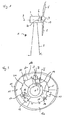
- FIG. 1 schematically shows a wind turbine 1.
- the wind turbine 1 comprises a tower 2, a nacelle 3 and a hub 4.
- the nacelle 3 is located on top of the tower 2.
- the hub 4 comprises a number of wind turbine blades 5.
- the hub 4 is mounted to the nacelle 3.
- the hub 4 is pivot-mounted such that it is able to rotate about a rotation axis 9.
- a generator 6 is located inside the nacelle 3.
- the wind turbine 1 is a direct drive wind turbine.
- the generator 6 comprises a near side 19 facing the hub 4 and a far side 20 opposite to the hub 4.
- FIG. 2 schematically shows part of a generator 6 with an outer rotor configuration in a sectional view.
- the generator 6 comprises a stator assembly 7 and a rotor assembly 8.
- the stator assembly 7 comprises a stationary shaft 10 which is located close to the rotation axis 9.
- the rotor assembly 8 comprises an outer rotor portion 11 which is located radially outward of the stator assembly 7.
- the rotor assembly 8 further comprises a brake disc 12.
- the brake disc 12 may be part of the outer rotor portion 11 or it may be connected to the outer rotor portion 11.
- the brake disc 12 extends radially inward from the outer portion 11 to the rotation axis 9.
- the outer portion 11 of the rotor assembly 8 and the brake disc 12 are pivot-mounted about the rotation axis 9.
- the stator assembly 7 further comprises a frictional member, in the present embodiment a brake calliper system 13.
- the brake calliper system 13 is operatively configured for frictionally engaging at least a portion of the brake disc 12.
- the brake calliper system 13 extends radially outward from the stationary shaft 10 to the brake disc 12.
- the brake calliper system 13 comprises at least one brake calliper on each side of the brake disc 12 in order to enclose the brake disc 12.
- the radial distance 22 between the brake disc 12 and the brake calliper system 13 is less than the radial distance 23 (air gap) between the outer rotor portion 11 and the stator assembly 7.
- radial distance 22 is between 1 mm and 5 mm, preferably between 2 mm and 4 mm.
- the air gap 23 has a width between 4 mm and 10 mm, advantageously between 5 mm and 7 mm.
- FIG. 3 schematically shows a front view of the inventive brake system of the generator 6. Elements which correspond to elements of the previously described Figures are designated with the same reference numerals and will not be described again in detail.
- the brake disc 12 comprises an inner surface 21.
- the inner surface 21 of the brake disc 12 comprises a number of recesses 15.
- the recesses 15 are radially and/or symmetrically spaced in the inner surface 21.
- the brake disc 12 can be divided into radial segments 12a, 12b and 12c.
- the brake disc 12 can also be divided into any other number of radial segments. This makes it possible to exchange a large brake disc 12 easily.
- the brake system further comprises a number of central mounted flanges 14, in the present embodiment three central mounted flanges 14.
- the flanges 14 are mounted to the stationary shaft 10.
- the flanges 14 are staggered about an angle of 120° regarding the circumference of the stationary shaft 10.
- any other number of the flanges 14 is possible.
- the flanges 14 are arranged around the circumference of the stationary shaft 10 such that adjacent flanges have an equal distance to each other.
- the brake system comprises at least one rotor lock system 17.
- the rotor lock system 17 comprises at least one piston 16.
- the piston is located inside the flange 14 or is located inside of a lock casing.
- the lock casing can be connected to the flange 14.
- the brake system can comprise separate flanges for housing the pistons or for being connected with at least one lock casing of the rotor lock system 17 and separate flanges 14 being connected with the brake system, especially the brake calliper system 13.
- the pistons 16 are located such that they are prepared to engage with the recesses 15 in the inner surface 21 of the brake disc 12.
- the rotor lock system 17 comprises an automatic actuator.
- the automatic actuator may be configured for actuating the rotor lock.
- the rotor lock system 17 may comprise an automatic actuator for pushing the pistons 16 into the corresponding recesses 15.
- the actuator comprises hydraulic or electrical means, for instance a hydraulic cylinder.
- recesses also holes can be present in the brake disc 12 and instead of pistons also pins may be used.
- rotor lock system 17 comprising a number of pistons 16
- a lock system comprising an interlock, a snap-in lock, a block, an arrest, a barricade or a similar means may be used, but is not part of the present invention.
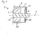
- Figure 4 schematically shows part of the inventive brake system in a sectional view along IV-IV of Figure 3 .
- two brake callipers 13A and 13B are located each on one side of the brake disc 12 opposite to each other.
- the two brake callipers 13A and 13B are connected to the central mounted flange 14.
- the flange 14 is connected to the stationary shaft 10.
- the brake disc is integrated part of the outer rotor portion 11.
- the brake disc 12 may be a separate element which is mounted to the outer rotor portion 11.
- the brake disc 12 can be fastened to a flange of a rotor support, for instance by bolts or screws.
- the actuation force for actuating the brake callipers 13A and 13B is designated by an arrow 18.
- the brake callipers 13A and 13B When the brake callipers 13A and 13B are actuated, they frictionally engage a portion of the brake disc 12.
- the wind turbine 1 may comprise a bed frame or a support structure of the stator.
- the brake calliper system 13 can be mounted directly to the bed frame of the wind turbine 1 or to the support structure of the stator.
- Figures 5 and 6 schematically show part of the inventive brake system in a sectional view along V-V of Figure 3 .
- the rotor lock system 17 is integrated into the brake system.
- Figure 5 schematically shows the rotor lock system in an unlocked state.
- Figure 6 shows the rotor lock system in a locked state.
- the piston 16 is completely located inside of the flange 14 or inside of another component of the rotor lock system 17, for example a lock casing.
- the piston 16 is pushed into a corresponding recess 15 of the brake disc 12. In this position the rotor is locked in a parking position.
- the piston 16 can be pushed into the corresponding recess 15 of the brake disc 12 by hydraulic or electrical means.
- the inventive brake system is located at the far side 20 of the generator 6 opposite to the hub 4. This allows for an easy access to the brake system and the integrated rotor lock system, especially for maintenance and service.
- the inventive brake system may be located at the hub.
- the inventive brake system may directly be connected to the hub.
- FIG. 7 schematically shows part of an inventive wind turbine 301. It comprises a typical and well known "one-bearing" arrangement.
- a wind turbine 301 comprises a direct drive generator 302, which is arranged on the upwind side of a tower 303 of the wind turbine 301.
- a tower flange 304 is arranged on the top of the tower 303.
- a bedplate 305 is attached to the tower flange 304.
- the wind turbine 401 comprises a yaw system - not shown here - which is used to turn the bedplate 305 of the wind turbine 301 around the axis 300.
- the wind turbine 301 comprises a stationary shaft 306, while the shaft 306 has a centre axis 200.
- the rear side of the stationary shaft 306 is attached to a retaining arrangement 307.
- a stator arrangement 308 of the direct drive generator 302 is arranged on the front side of the stationary shaft 306 .
- the stator arrangement 308 comprises a stator support structure 309 and a lamination stack 310.
- the lamination stack 310 supports windings 311.
- the stator support structure 309 comprises two support elements 312 for a two side support of the lamination stack 310.
- the support elements 312 are ring-shaped. They are attached to the outside of the stationary shaft 306.
- a hollow cylindrical support element 313 is attached to the outer ends of the ring-shaped support elements 312.
- the hollow cylindrical support element 313 carries the ring-shaped lamination stack 310 and the windings 311.
- a rotor arrangement 314 is arranged around the stator arrangement 308.
- the rotor arrangement 314 comprises a front endplate 315 and a cylinder element 317.
- the front endplate 315 is ring-shaped, while the cylinder element 317 is hollow.
- the cylinder element 317 comprises a plurality of permanent magnets 318, which are mounted on the inside of the hollow cylinder element 317.
- the permanent magnets 318 are arranged opposite to the lamination stack 310 and the supported windings.
- An air gap 319 with a width of approximately 6 mm is located between the permanent magnets 318 and the lamination stack 310.
- the air gap 319 has a width between 4 mm and 10 mm, advantageously between 5 mm and 7 mm.
- a brake disc 12 is connected to the cylinder element 317 of the rotor.
- a brake calliper system 13 is connected to the stationary shaft 306.
- the radial distance 22 between the brake calliper system 13 and the brake disc 12 is less than the air gap 319.
- radial distance 22 is between 1 mm and 5 mm, preferably between 2 mm and 4 mm.
- the front endplate 315 is arranged on the stationary shaft 306 via a bearing 320.
- the bearing 320 is capable to transform axial loads in both directions of the centre axis A.
- An appropriate bearing is disclosed in DE 201 16 649 U1 for example.
- the stationary part 321 of the bearing 320 is attached to the stationary shaft 306.
- the rotating part 322 of the bearing 320 is connected to a mounting ring 323.
- the front endplate 315 as well as the hub 324 are attached to the mounting ring 323.
- the hub 324 comprises mounting devices 325 for wind turbine rotor blades - not shown here.
- the air gap 319 shown here is uniform to achieve a constant distance between the elements of the rotor and the elements of the stator.
- the one bearing design is very attractive due to its easy design.
Claims (15)
- Bremssystem für eine Windenergieanlage (1),
bei dem ein Rotorsperrsystem (17) in das Bremssystem integriert ist und das Bremssystem eine Rotorbaugruppe (8) und eine Statorbaugruppe (7) umfasst, wobei die Rotorbaugruppe (8) eine Bremsscheibe (12) mit einer radial innen liegenden Fläche (21) umfasst,
dadurch gekennzeichnet, dass
die radial innen liegende Fläche (21) eine Anzahl Aussparungen (15) und die Statorbaugruppe (7) mindestens einen Kolben (16) umfasst, der so angeordnet ist, dass er zum Eingreifen in die Aussparungen (15) bereitsteht. - Bremssystem nach Anspruch 1, bei dem das Rotorsperrsystem (17) ein automatisches Stellglied zum Betätigen der Sperre umfasst.
- Bremssystem nach Anspruch 2, bei dem das automatische Stellglied hydraulische oder elektrische Mittel umfasst.
- Bremssystem nach einem der Ansprüche 1 bis 3, bei dem das Sperrsystem (17) ein automatisches Stellglied zum Drücken des Kolbens (16) in die entsprechende Aussparung (15) umfasst.
- Bremssystem nach einem der Ansprüche 1 bis 4, wobei das Bremssystem eine Rotorbaugruppe (8), eine Statorbaugruppe (7) und eine Rotationsachse (9) umfasst, wobei die Rotorbaugruppe (8) einen Außenabschnitt (11) umfasst, der von der Statorbaugruppe (7) aus radial außen liegt, wobei der Außenabschnitt (11) eine Bremsscheibe (12) und die Statorbaugruppe (7) mindestens ein Reibungselement (13) umfasst, das funktionsmäßig so konfiguriert ist, dass es zumindest an einem Abschnitt der Bremsscheibe (12) reibschlüssig anliegt.
- Bremssystem nach Anspruch 5, bei dem die Bremsscheibe (12) von dem Außenabschnitt (11) der Rotorbaugruppe (8) radial nach innen zur Rotationsachse (9) verläuft.
- Bremssystem nach Anspruch 5 oder 6, bei dem die Statorbaugruppe (7) eine feststehende Welle (10) oder einen Grundrahmen einer Windenergieanlage (1) oder eine Statortragekonstruktion umfasst und das mindestens eine Reibungselement (13) mit der feststehenden Welle (10) oder dem Grundrahmen oder der Statortragekonstruktion verbunden ist.
- Bremssystem nach einem der Ansprüche 5 bis 7, bei dem das mindestens eine Reibungselement (13) in Bezug auf die Rotationsachse (9) radial nach außen verläuft.
- Bremssystem nach einem der Ansprüche 5 bis 8, bei dem das Reibungselement (13) mindestens einen Bremssattel umfasst.
- Bremssystem nach einem der Ansprüche 5 bis 9, bei dem das mindestens eine Reibungselement (13) mindestens ein Bremssattelsystem umfasst, das mindestens zwei Bremssättel umfasst, die sich auf jeder Seite der Bremsscheibe (12) gegenüberliegen.
- Bremssystem nach einem der Ansprüche 1 bis 10, bei dem die Bremsscheibe (12) eine Anzahl radialer Segmente (12a, 12b, 12c) umfasst.
- Generator (6), der ein Bremssystem nach einem der Ansprüche 1 bis 11 umfasst.
- Generator (6) nach Anspruch 12, wobei der Generator (6) einen Rotor und einen Stator umfasst und der radiale Abstand (22) zwischen der Bremsscheibe (12) und dem Reibungselement (13) geringer ist als der radiale Abstand (23) zwischen dem Rotor und dem Stator.
- Windenergieanlage (1), die ein Bremssystem nach einem der Ansprüche 1 bis 11 und/ oder einen Generator nach Anspruch 12 oder 13 umfasst.
- Windenergieanlage (1) nach Anspruch 14, wobei die Windenergieanlage (1) einen Generator (6) und/ oder eine Nabe (4) umfasst und das Bremssystem mit dem Generator (6) und/ oder der Nabe (4) verbunden ist.
Priority Applications (7)
| Application Number | Priority Date | Filing Date | Title |
|---|---|---|---|
| EP09014765.3A EP2333326B1 (de) | 2009-11-26 | 2009-11-26 | Bremssystem mit integrierter Rotorsperre für eine Windturbine, Generator und Windturbine |
| DK09014765.3T DK2333326T3 (da) | 2009-11-26 | 2009-11-26 | Bremsesystem til en vindmølle med integreret rotorlås, generator og vindmølle |
| US12/951,349 US8740566B2 (en) | 2009-11-26 | 2010-11-22 | Brake system for a wind turbine with integrated rotor lock generator and wind turbine |
| CA2722721A CA2722721C (en) | 2009-11-26 | 2010-11-24 | Brake system for a wind turbine with integrated rotor lock, generator and wind turbine |
| NZ589530A NZ589530A (en) | 2009-11-26 | 2010-11-25 | Brake system for wind turbine with rotor lock having outer rotor having recesses and inner stator having piston to engage in recesses |
| JP2010263883A JP5773621B2 (ja) | 2009-11-26 | 2010-11-26 | 一体化されたロータロックを備えた風車のためのブレーキシステム、発電機、及び風車 |
| CN201010561814.4A CN102080629B (zh) | 2009-11-26 | 2010-11-26 | 风轮机的具有整体转子锁的制动系统、发电机和风轮机 |
Applications Claiming Priority (1)
| Application Number | Priority Date | Filing Date | Title |
|---|---|---|---|
| EP09014765.3A EP2333326B1 (de) | 2009-11-26 | 2009-11-26 | Bremssystem mit integrierter Rotorsperre für eine Windturbine, Generator und Windturbine |
Publications (2)
| Publication Number | Publication Date |
|---|---|
| EP2333326A1 EP2333326A1 (de) | 2011-06-15 |
| EP2333326B1 true EP2333326B1 (de) | 2013-07-17 |
Family
ID=42617469
Family Applications (1)
| Application Number | Title | Priority Date | Filing Date |
|---|---|---|---|
| EP09014765.3A Active EP2333326B1 (de) | 2009-11-26 | 2009-11-26 | Bremssystem mit integrierter Rotorsperre für eine Windturbine, Generator und Windturbine |
Country Status (7)
| Country | Link |
|---|---|
| US (1) | US8740566B2 (de) |
| EP (1) | EP2333326B1 (de) |
| JP (1) | JP5773621B2 (de) |
| CN (1) | CN102080629B (de) |
| CA (1) | CA2722721C (de) |
| DK (1) | DK2333326T3 (de) |
| NZ (1) | NZ589530A (de) |
Families Citing this family (25)
| Publication number | Priority date | Publication date | Assignee | Title |
|---|---|---|---|---|
| GB2461285B (en) * | 2008-06-26 | 2012-07-25 | Converteam Technology Ltd | Vertical axis wind turbines |
| EP2437380A1 (de) * | 2010-09-30 | 2012-04-04 | Siemens Aktiengesellschaft | Rotor, Generator und Windturbine |
| WO2013042251A1 (ja) * | 2011-09-22 | 2013-03-28 | 三菱重工業株式会社 | 再生エネルギー型発電装置及びその回転翼着脱方法 |
| US9124153B2 (en) * | 2011-01-05 | 2015-09-01 | Vestas Wind Systems A/S | Direct drive generator |
| EP2584673A1 (de) * | 2011-10-17 | 2013-04-24 | ABB Oy | Elektrische Maschine mit Dämpfungsmitteln |
| CN102635516B (zh) * | 2012-05-15 | 2015-01-21 | 南京风电科技有限公司 | 径向风轮锁定装置 |
| DK2669510T3 (da) * | 2012-05-30 | 2014-10-06 | Siemens Ag | Bremsesystem til en vindmølle |
| US20140010656A1 (en) * | 2012-07-05 | 2014-01-09 | Jacob Johannes Nies | Fixation device |
| US9470208B2 (en) * | 2012-07-05 | 2016-10-18 | General Electric Company | Wind turbine and locking method |
| CN102937072B (zh) * | 2012-11-23 | 2015-07-15 | 国电联合动力技术有限公司 | 一种具有新型叶轮锁紧形式的双定子直驱风力发电机组 |
| CN202926533U (zh) * | 2012-11-29 | 2013-05-08 | 北京金风科创风电设备有限公司 | 风力发电机及用于风力发电机的叶轮锁定装置 |
| DE102013206002A1 (de) * | 2013-04-04 | 2014-10-09 | Senvion Se | Verfahren und Einrichtung zum Ein- und/oder Auskoppeln eines Getriebe-Hilfsantriebs, Windenergieanlage |
| CN103334881A (zh) * | 2013-07-24 | 2013-10-02 | 国电联合动力技术有限公司 | 一种外转子风力发电机组 |
| DK2896824T3 (en) * | 2014-01-20 | 2016-08-29 | Siemens Ag | Brake system for a wind turbine generator |
| DK178152B1 (en) * | 2014-09-02 | 2015-07-06 | Envision Energy Denmark Aps | Wind turbine rotor lock system |
| CN104454356B (zh) * | 2014-10-17 | 2017-10-20 | 交城新华机械有限公司 | 一种风力发电机 |
| JP6207092B2 (ja) | 2015-02-17 | 2017-10-04 | 三菱重工業株式会社 | 水流発電機 |
| DE102016116945A1 (de) * | 2016-09-09 | 2018-03-15 | Wobben Properties Gmbh | Rotorarretiervorrichtung für eine Windenergieanlage und Verfahren |
| DE102018104627A1 (de) * | 2018-02-28 | 2019-10-10 | Wobben Properties Gmbh | Generator einer Windenergieanlage, Windenergieanlage mit selbigem, Verfahren zum Arretieren eines Generators sowie Verwendung einer Arretiervorrichtung |
| ES2937691T3 (es) | 2019-02-14 | 2023-03-30 | Siemens Gamesa Renewable Energy As | Sistema de seguridad para una turbina eólica |
| CN110195685B (zh) * | 2019-05-27 | 2020-11-27 | 上海电气风电集团股份有限公司 | 刹车系统及外转子式直驱风力发电机组 |
| CN112664392A (zh) | 2019-10-15 | 2021-04-16 | 通用电气公司 | 用于在延长的维护期间锁定风力涡轮转子的系统和方法 |
| US20220412311A1 (en) * | 2019-12-10 | 2022-12-29 | Siemens Gamesa Renewable Energy A/S | Locking system for a rotatable mounted unit of a wind turbine, wind turbine and method for operating a locking system |
| CN111648918A (zh) * | 2020-05-13 | 2020-09-11 | 包红喜 | 一种使用寿命长的风力发电设备 |
| CN114893521B (zh) * | 2022-05-27 | 2023-09-26 | 中国船舶集团有限公司第七二三研究所 | 一种转角范围超360°的机械和电气限位机构 |
Family Cites Families (12)
| Publication number | Priority date | Publication date | Assignee | Title |
|---|---|---|---|---|
| US4460838A (en) * | 1982-08-06 | 1984-07-17 | Ecm Motor Co. | Electric motor with braking arrangement |
| JPS60220232A (ja) * | 1984-04-17 | 1985-11-02 | Kawasaki Heavy Ind Ltd | ブレ−キデイスク |
| DE4402184C2 (de) | 1994-01-26 | 1995-11-23 | Friedrich Prof Dr Ing Klinger | Vielpol-Synchrongenerator für getriebelose Horizontalachsen-Windkraftanlagen mit Nennleistungen bis zu mehreren Megawatt |
| CA2369229A1 (en) * | 2002-01-24 | 2003-07-24 | Jacquelin Dery | Vertical axis windmill and self-erecting structure therefor |
| JP2004225568A (ja) * | 2003-01-21 | 2004-08-12 | Ebara Corp | 垂直軸風車およびその安全装置 |
| US7431567B1 (en) * | 2003-05-30 | 2008-10-07 | Northern Power Systems Inc. | Wind turbine having a direct-drive drivetrain |
| US7075192B2 (en) | 2004-04-19 | 2006-07-11 | Northern Power Systems, Inc. | Direct drive wind turbine |
| US7467530B2 (en) * | 2005-07-29 | 2008-12-23 | New Hampton Technologies Llc | Vehicle lock |
| US7581921B2 (en) * | 2006-06-19 | 2009-09-01 | General Electric Company | Methods and apparatus for controlling rotary machines |
| ATE487060T1 (de) | 2006-11-23 | 2010-11-15 | Stx Heavy Ind Co Ltd | Hauptlager einer windkraftanlage |
| US7948100B2 (en) * | 2007-12-19 | 2011-05-24 | General Electric Company | Braking and positioning system for a wind turbine rotor |
| CN101482097B (zh) | 2009-01-21 | 2012-01-25 | 严强 | 一种用于垂直轴风力发电机的制动系统及其制动方法 |
-
2009
- 2009-11-26 DK DK09014765.3T patent/DK2333326T3/da active
- 2009-11-26 EP EP09014765.3A patent/EP2333326B1/de active Active
-
2010
- 2010-11-22 US US12/951,349 patent/US8740566B2/en active Active
- 2010-11-24 CA CA2722721A patent/CA2722721C/en not_active Expired - Fee Related
- 2010-11-25 NZ NZ589530A patent/NZ589530A/en not_active IP Right Cessation
- 2010-11-26 CN CN201010561814.4A patent/CN102080629B/zh active Active
- 2010-11-26 JP JP2010263883A patent/JP5773621B2/ja not_active Expired - Fee Related
Also Published As
| Publication number | Publication date |
|---|---|
| EP2333326A1 (de) | 2011-06-15 |
| US8740566B2 (en) | 2014-06-03 |
| US20110123339A1 (en) | 2011-05-26 |
| JP5773621B2 (ja) | 2015-09-02 |
| CN102080629B (zh) | 2014-11-26 |
| JP2011112055A (ja) | 2011-06-09 |
| NZ589530A (en) | 2011-08-26 |
| CA2722721A1 (en) | 2011-05-26 |
| CA2722721C (en) | 2018-06-12 |
| DK2333326T3 (da) | 2013-08-12 |
| CN102080629A (zh) | 2011-06-01 |
Similar Documents
| Publication | Publication Date | Title |
|---|---|---|
| EP2333326B1 (de) | Bremssystem mit integrierter Rotorsperre für eine Windturbine, Generator und Windturbine | |
| EP2333325B1 (de) | Bremssystem, Generator und Windturbine | |
| EP2143936B1 (de) | Windturbine mit einem Hauptlager und Verfahren zum Ersetzen des Hauptlagers | |
| EP1925820B1 (de) | Hauptlager einer Windkraftanlage | |
| US20120181792A1 (en) | Wind turbine | |
| US8975770B2 (en) | Wind power turbine electric generator and wind power turbine equipped with an electric generator | |
| CN102308087A (zh) | 用于风力发电机的转子的锁定装置 | |
| KR20030011902A (ko) | 풍력 에너지로부터 전류를 발생시키는 장치 | |
| US10454342B2 (en) | Rotational movement control of an electric generator by means of a turning device | |
| US20140147279A1 (en) | Brake system with expansion absorbing means, generator and wind turbine | |
| EP2896824B1 (de) | Bremssystem für einen Windturbinengenerator | |
| EP3226384A1 (de) | Drehbewegungssteuerung eines elektrischen generators mittels einer drehvorrichtung | |
| US20190195197A1 (en) | Rotor arresting device for a wind turbine and method | |
| EP2607684B1 (de) | Mittel zum Drehen des Rotors einer Windturbine und Verfahren zum Drehen des Rotors |
Legal Events
| Date | Code | Title | Description |
|---|---|---|---|
| PUAI | Public reference made under article 153(3) epc to a published international application that has entered the european phase |
Free format text: ORIGINAL CODE: 0009012 |
|
| AK | Designated contracting states |
Kind code of ref document: A1 Designated state(s): AT BE BG CH CY CZ DE DK EE ES FI FR GB GR HR HU IE IS IT LI LT LU LV MC MK MT NL NO PL PT RO SE SI SK SM TR |
|
| AX | Request for extension of the european patent |
Extension state: AL BA RS |
|
| 17P | Request for examination filed |
Effective date: 20110704 |
|
| 17Q | First examination report despatched |
Effective date: 20130118 |
|
| GRAP | Despatch of communication of intention to grant a patent |
Free format text: ORIGINAL CODE: EPIDOSNIGR1 |
|
| RIC1 | Information provided on ipc code assigned before grant |
Ipc: F03D 7/02 20060101ALI20130122BHEP Ipc: F03D 9/00 20060101AFI20130122BHEP Ipc: F03D 11/00 20060101ALI20130122BHEP |
|
| RAP1 | Party data changed (applicant data changed or rights of an application transferred) |
Owner name: SIEMENS AKTIENGESELLSCHAFT |
|
| GRAS | Grant fee paid |
Free format text: ORIGINAL CODE: EPIDOSNIGR3 |
|
| GRAA | (expected) grant |
Free format text: ORIGINAL CODE: 0009210 |
|
| AK | Designated contracting states |
Kind code of ref document: B1 Designated state(s): AT BE BG CH CY CZ DE DK EE ES FI FR GB GR HR HU IE IS IT LI LT LU LV MC MK MT NL NO PL PT RO SE SI SK SM TR |
|
| REG | Reference to a national code |
Ref country code: GB Ref legal event code: FG4D |
|
| REG | Reference to a national code |
Ref country code: CH Ref legal event code: EP |
|
| REG | Reference to a national code |
Ref country code: DK Ref legal event code: T3 |
|
| REG | Reference to a national code |
Ref country code: IE Ref legal event code: FG4D |
|
| REG | Reference to a national code |
Ref country code: AT Ref legal event code: REF Ref document number: 622393 Country of ref document: AT Kind code of ref document: T Effective date: 20130815 |
|
| REG | Reference to a national code |
Ref country code: DE Ref legal event code: R096 Ref document number: 602009017154 Country of ref document: DE Effective date: 20130912 |
|
| REG | Reference to a national code |
Ref country code: AT Ref legal event code: MK05 Ref document number: 622393 Country of ref document: AT Kind code of ref document: T Effective date: 20130717 |
|
| REG | Reference to a national code |
Ref country code: NL Ref legal event code: VDEP Effective date: 20130717 |
|
| REG | Reference to a national code |
Ref country code: LT Ref legal event code: MG4D |
|
| PG25 | Lapsed in a contracting state [announced via postgrant information from national office to epo] |
Ref country code: BE Free format text: LAPSE BECAUSE OF FAILURE TO SUBMIT A TRANSLATION OF THE DESCRIPTION OR TO PAY THE FEE WITHIN THE PRESCRIBED TIME-LIMIT Effective date: 20130717 Ref country code: LT Free format text: LAPSE BECAUSE OF FAILURE TO SUBMIT A TRANSLATION OF THE DESCRIPTION OR TO PAY THE FEE WITHIN THE PRESCRIBED TIME-LIMIT Effective date: 20130717 Ref country code: SE Free format text: LAPSE BECAUSE OF FAILURE TO SUBMIT A TRANSLATION OF THE DESCRIPTION OR TO PAY THE FEE WITHIN THE PRESCRIBED TIME-LIMIT Effective date: 20130717 Ref country code: NO Free format text: LAPSE BECAUSE OF FAILURE TO SUBMIT A TRANSLATION OF THE DESCRIPTION OR TO PAY THE FEE WITHIN THE PRESCRIBED TIME-LIMIT Effective date: 20131017 Ref country code: CY Free format text: LAPSE BECAUSE OF FAILURE TO SUBMIT A TRANSLATION OF THE DESCRIPTION OR TO PAY THE FEE WITHIN THE PRESCRIBED TIME-LIMIT Effective date: 20130724 Ref country code: HR Free format text: LAPSE BECAUSE OF FAILURE TO SUBMIT A TRANSLATION OF THE DESCRIPTION OR TO PAY THE FEE WITHIN THE PRESCRIBED TIME-LIMIT Effective date: 20130717 Ref country code: AT Free format text: LAPSE BECAUSE OF FAILURE TO SUBMIT A TRANSLATION OF THE DESCRIPTION OR TO PAY THE FEE WITHIN THE PRESCRIBED TIME-LIMIT Effective date: 20130717 Ref country code: PT Free format text: LAPSE BECAUSE OF FAILURE TO SUBMIT A TRANSLATION OF THE DESCRIPTION OR TO PAY THE FEE WITHIN THE PRESCRIBED TIME-LIMIT Effective date: 20131118 Ref country code: IS Free format text: LAPSE BECAUSE OF FAILURE TO SUBMIT A TRANSLATION OF THE DESCRIPTION OR TO PAY THE FEE WITHIN THE PRESCRIBED TIME-LIMIT Effective date: 20131117 |
|
| PG25 | Lapsed in a contracting state [announced via postgrant information from national office to epo] |
Ref country code: FI Free format text: LAPSE BECAUSE OF FAILURE TO SUBMIT A TRANSLATION OF THE DESCRIPTION OR TO PAY THE FEE WITHIN THE PRESCRIBED TIME-LIMIT Effective date: 20130717 Ref country code: ES Free format text: LAPSE BECAUSE OF FAILURE TO SUBMIT A TRANSLATION OF THE DESCRIPTION OR TO PAY THE FEE WITHIN THE PRESCRIBED TIME-LIMIT Effective date: 20131028 Ref country code: SI Free format text: LAPSE BECAUSE OF FAILURE TO SUBMIT A TRANSLATION OF THE DESCRIPTION OR TO PAY THE FEE WITHIN THE PRESCRIBED TIME-LIMIT Effective date: 20130717 Ref country code: PL Free format text: LAPSE BECAUSE OF FAILURE TO SUBMIT A TRANSLATION OF THE DESCRIPTION OR TO PAY THE FEE WITHIN THE PRESCRIBED TIME-LIMIT Effective date: 20130717 Ref country code: NL Free format text: LAPSE BECAUSE OF FAILURE TO SUBMIT A TRANSLATION OF THE DESCRIPTION OR TO PAY THE FEE WITHIN THE PRESCRIBED TIME-LIMIT Effective date: 20130717 Ref country code: GR Free format text: LAPSE BECAUSE OF FAILURE TO SUBMIT A TRANSLATION OF THE DESCRIPTION OR TO PAY THE FEE WITHIN THE PRESCRIBED TIME-LIMIT Effective date: 20131018 Ref country code: LV Free format text: LAPSE BECAUSE OF FAILURE TO SUBMIT A TRANSLATION OF THE DESCRIPTION OR TO PAY THE FEE WITHIN THE PRESCRIBED TIME-LIMIT Effective date: 20130717 |
|
| PG25 | Lapsed in a contracting state [announced via postgrant information from national office to epo] |
Ref country code: CY Free format text: LAPSE BECAUSE OF FAILURE TO SUBMIT A TRANSLATION OF THE DESCRIPTION OR TO PAY THE FEE WITHIN THE PRESCRIBED TIME-LIMIT Effective date: 20130717 |
|
| PLBI | Opposition filed |
Free format text: ORIGINAL CODE: 0009260 |
|
| PG25 | Lapsed in a contracting state [announced via postgrant information from national office to epo] |
Ref country code: SK Free format text: LAPSE BECAUSE OF FAILURE TO SUBMIT A TRANSLATION OF THE DESCRIPTION OR TO PAY THE FEE WITHIN THE PRESCRIBED TIME-LIMIT Effective date: 20130717 Ref country code: CZ Free format text: LAPSE BECAUSE OF FAILURE TO SUBMIT A TRANSLATION OF THE DESCRIPTION OR TO PAY THE FEE WITHIN THE PRESCRIBED TIME-LIMIT Effective date: 20130717 Ref country code: EE Free format text: LAPSE BECAUSE OF FAILURE TO SUBMIT A TRANSLATION OF THE DESCRIPTION OR TO PAY THE FEE WITHIN THE PRESCRIBED TIME-LIMIT Effective date: 20130717 Ref country code: RO Free format text: LAPSE BECAUSE OF FAILURE TO SUBMIT A TRANSLATION OF THE DESCRIPTION OR TO PAY THE FEE WITHIN THE PRESCRIBED TIME-LIMIT Effective date: 20130717 |
|
| PLAB | Opposition data, opponent's data or that of the opponent's representative modified |
Free format text: ORIGINAL CODE: 0009299OPPO |
|
| 26 | Opposition filed |
Opponent name: ENERCON GMBH Effective date: 20140417 |
|
| PLAX | Notice of opposition and request to file observation + time limit sent |
Free format text: ORIGINAL CODE: EPIDOSNOBS2 |
|
| PG25 | Lapsed in a contracting state [announced via postgrant information from national office to epo] |
Ref country code: IT Free format text: LAPSE BECAUSE OF FAILURE TO SUBMIT A TRANSLATION OF THE DESCRIPTION OR TO PAY THE FEE WITHIN THE PRESCRIBED TIME-LIMIT Effective date: 20130717 |
|
| R26 | Opposition filed (corrected) |
Opponent name: ENERCON GMBH Effective date: 20140417 |
|
| REG | Reference to a national code |
Ref country code: DE Ref legal event code: R026 Ref document number: 602009017154 Country of ref document: DE Effective date: 20140417 |
|
| REG | Reference to a national code |
Ref country code: CH Ref legal event code: PL |
|
| PG25 | Lapsed in a contracting state [announced via postgrant information from national office to epo] |
Ref country code: MC Free format text: LAPSE BECAUSE OF FAILURE TO SUBMIT A TRANSLATION OF THE DESCRIPTION OR TO PAY THE FEE WITHIN THE PRESCRIBED TIME-LIMIT Effective date: 20130717 Ref country code: LI Free format text: LAPSE BECAUSE OF NON-PAYMENT OF DUE FEES Effective date: 20131130 Ref country code: CH Free format text: LAPSE BECAUSE OF NON-PAYMENT OF DUE FEES Effective date: 20131130 |
|
| REG | Reference to a national code |
Ref country code: FR Ref legal event code: ST Effective date: 20140731 |
|
| REG | Reference to a national code |
Ref country code: IE Ref legal event code: MM4A |
|
| PLAF | Information modified related to communication of a notice of opposition and request to file observations + time limit |
Free format text: ORIGINAL CODE: EPIDOSCOBS2 |
|
| PG25 | Lapsed in a contracting state [announced via postgrant information from national office to epo] |
Ref country code: IE Free format text: LAPSE BECAUSE OF NON-PAYMENT OF DUE FEES Effective date: 20131126 |
|
| PLBB | Reply of patent proprietor to notice(s) of opposition received |
Free format text: ORIGINAL CODE: EPIDOSNOBS3 |
|
| PG25 | Lapsed in a contracting state [announced via postgrant information from national office to epo] |
Ref country code: FR Free format text: LAPSE BECAUSE OF NON-PAYMENT OF DUE FEES Effective date: 20131202 |
|
| PLAY | Examination report in opposition despatched + time limit |
Free format text: ORIGINAL CODE: EPIDOSNORE2 |
|
| PG25 | Lapsed in a contracting state [announced via postgrant information from national office to epo] |
Ref country code: SM Free format text: LAPSE BECAUSE OF FAILURE TO SUBMIT A TRANSLATION OF THE DESCRIPTION OR TO PAY THE FEE WITHIN THE PRESCRIBED TIME-LIMIT Effective date: 20130717 |
|
| PG25 | Lapsed in a contracting state [announced via postgrant information from national office to epo] |
Ref country code: TR Free format text: LAPSE BECAUSE OF FAILURE TO SUBMIT A TRANSLATION OF THE DESCRIPTION OR TO PAY THE FEE WITHIN THE PRESCRIBED TIME-LIMIT Effective date: 20130717 |
|
| PG25 | Lapsed in a contracting state [announced via postgrant information from national office to epo] |
Ref country code: BG Free format text: LAPSE BECAUSE OF FAILURE TO SUBMIT A TRANSLATION OF THE DESCRIPTION OR TO PAY THE FEE WITHIN THE PRESCRIBED TIME-LIMIT Effective date: 20130717 Ref country code: LU Free format text: LAPSE BECAUSE OF NON-PAYMENT OF DUE FEES Effective date: 20131126 Ref country code: MK Free format text: LAPSE BECAUSE OF FAILURE TO SUBMIT A TRANSLATION OF THE DESCRIPTION OR TO PAY THE FEE WITHIN THE PRESCRIBED TIME-LIMIT Effective date: 20130717 Ref country code: HU Free format text: LAPSE BECAUSE OF FAILURE TO SUBMIT A TRANSLATION OF THE DESCRIPTION OR TO PAY THE FEE WITHIN THE PRESCRIBED TIME-LIMIT; INVALID AB INITIO Effective date: 20091126 |
|
| PG25 | Lapsed in a contracting state [announced via postgrant information from national office to epo] |
Ref country code: MT Free format text: LAPSE BECAUSE OF FAILURE TO SUBMIT A TRANSLATION OF THE DESCRIPTION OR TO PAY THE FEE WITHIN THE PRESCRIBED TIME-LIMIT Effective date: 20130717 |
|
| PLAH | Information related to despatch of examination report in opposition + time limit modified |
Free format text: ORIGINAL CODE: EPIDOSCORE2 |
|
| PLBC | Reply to examination report in opposition received |
Free format text: ORIGINAL CODE: EPIDOSNORE3 |
|
| PLBP | Opposition withdrawn |
Free format text: ORIGINAL CODE: 0009264 |
|
| RAP2 | Party data changed (patent owner data changed or rights of a patent transferred) |
Owner name: SIEMENS AKTIENGESELLSCHAFT |
|
| PLBD | Termination of opposition procedure: decision despatched |
Free format text: ORIGINAL CODE: EPIDOSNOPC1 |
|
| REG | Reference to a national code |
Ref country code: DE Ref legal event code: R100 Ref document number: 602009017154 Country of ref document: DE |
|
| PLBM | Termination of opposition procedure: date of legal effect published |
Free format text: ORIGINAL CODE: 0009276 |
|
| STAA | Information on the status of an ep patent application or granted ep patent |
Free format text: STATUS: OPPOSITION PROCEDURE CLOSED |
|
| 27C | Opposition proceedings terminated |
Effective date: 20171015 |
|
| REG | Reference to a national code |
Ref country code: DE Ref legal event code: R081 Ref document number: 602009017154 Country of ref document: DE Owner name: SIEMENS GAMESA RENEWABLE ENERGY A/S, DK Free format text: FORMER OWNER: SIEMENS AKTIENGESELLSCHAFT, 80333 MUENCHEN, DE |
|
| REG | Reference to a national code |
Ref country code: GB Ref legal event code: 732E Free format text: REGISTERED BETWEEN 20191128 AND 20191204 |
|
| PGFP | Annual fee paid to national office [announced via postgrant information from national office to epo] |
Ref country code: GB Payment date: 20221123 Year of fee payment: 14 Ref country code: DK Payment date: 20221122 Year of fee payment: 14 Ref country code: DE Payment date: 20221121 Year of fee payment: 14 |
|
| P01 | Opt-out of the competence of the unified patent court (upc) registered |
Effective date: 20230530 |