EP2333295A1 - Fuel feed system of engine - Google Patents
Fuel feed system of engine Download PDFInfo
- Publication number
- EP2333295A1 EP2333295A1 EP11156259A EP11156259A EP2333295A1 EP 2333295 A1 EP2333295 A1 EP 2333295A1 EP 11156259 A EP11156259 A EP 11156259A EP 11156259 A EP11156259 A EP 11156259A EP 2333295 A1 EP2333295 A1 EP 2333295A1
- Authority
- EP
- European Patent Office
- Prior art keywords
- negative pressure
- engine
- fuel
- engine case
- auto
- Prior art date
- Legal status (The legal status is an assumption and is not a legal conclusion. Google has not performed a legal analysis and makes no representation as to the accuracy of the status listed.)
- Granted
Links
- 239000000446 fuel Substances 0.000 title claims abstract description 160
- 239000007788 liquid Substances 0.000 claims abstract description 34
- 239000003595 mist Substances 0.000 claims abstract description 32
- 230000010349 pulsation Effects 0.000 claims abstract description 21
- 230000029058 respiratory gaseous exchange Effects 0.000 claims abstract description 12
- 239000002828 fuel tank Substances 0.000 claims description 45
- 230000001105 regulatory effect Effects 0.000 claims description 7
- 230000007257 malfunction Effects 0.000 abstract description 7
- 230000008595 infiltration Effects 0.000 abstract description 5
- 238000001764 infiltration Methods 0.000 abstract description 5
- 238000009825 accumulation Methods 0.000 abstract description 4
- 235000014676 Phragmites communis Nutrition 0.000 description 10
- 230000001276 controlling effect Effects 0.000 description 5
- 238000004891 communication Methods 0.000 description 4
- 230000000149 penetrating effect Effects 0.000 description 4
- 241001247986 Calotropis procera Species 0.000 description 3
- 238000013459 approach Methods 0.000 description 3
- 230000005484 gravity Effects 0.000 description 3
- 238000002485 combustion reaction Methods 0.000 description 2
- 230000000694 effects Effects 0.000 description 2
- 238000003780 insertion Methods 0.000 description 2
- 230000037431 insertion Effects 0.000 description 2
- 238000012986 modification Methods 0.000 description 2
- 230000004048 modification Effects 0.000 description 2
- 230000002441 reversible effect Effects 0.000 description 2
- 238000007789 sealing Methods 0.000 description 2
- 238000000926 separation method Methods 0.000 description 2
- 125000006850 spacer group Chemical group 0.000 description 2
- 239000007858 starting material Substances 0.000 description 2
- 238000009833 condensation Methods 0.000 description 1
- 230000005494 condensation Effects 0.000 description 1
- 238000010276 construction Methods 0.000 description 1
- 238000013461 design Methods 0.000 description 1
- 239000013013 elastic material Substances 0.000 description 1
- 230000001050 lubricating effect Effects 0.000 description 1
- 239000000203 mixture Substances 0.000 description 1
- 238000005192 partition Methods 0.000 description 1
- 230000003014 reinforcing effect Effects 0.000 description 1
- 238000004904 shortening Methods 0.000 description 1
- 239000000126 substance Substances 0.000 description 1
Images


Classifications
-
- F—MECHANICAL ENGINEERING; LIGHTING; HEATING; WEAPONS; BLASTING
- F02—COMBUSTION ENGINES; HOT-GAS OR COMBUSTION-PRODUCT ENGINE PLANTS
- F02M—SUPPLYING COMBUSTION ENGINES IN GENERAL WITH COMBUSTIBLE MIXTURES OR CONSTITUENTS THEREOF
- F02M37/00—Apparatus or systems for feeding liquid fuel from storage containers to carburettors or fuel-injection apparatus; Arrangements for purifying liquid fuel specially adapted for, or arranged on, internal-combustion engines
-
- F—MECHANICAL ENGINEERING; LIGHTING; HEATING; WEAPONS; BLASTING
- F01—MACHINES OR ENGINES IN GENERAL; ENGINE PLANTS IN GENERAL; STEAM ENGINES
- F01M—LUBRICATING OF MACHINES OR ENGINES IN GENERAL; LUBRICATING INTERNAL COMBUSTION ENGINES; CRANKCASE VENTILATING
- F01M13/00—Crankcase ventilating or breathing
- F01M13/04—Crankcase ventilating or breathing having means for purifying air before leaving crankcase, e.g. removing oil
-
- F—MECHANICAL ENGINEERING; LIGHTING; HEATING; WEAPONS; BLASTING
- F01—MACHINES OR ENGINES IN GENERAL; ENGINE PLANTS IN GENERAL; STEAM ENGINES
- F01M—LUBRICATING OF MACHINES OR ENGINES IN GENERAL; LUBRICATING INTERNAL COMBUSTION ENGINES; CRANKCASE VENTILATING
- F01M11/00—Component parts, details or accessories, not provided for in, or of interest apart from, groups F01M1/00 - F01M9/00
- F01M11/08—Separating lubricant from air or fuel-air mixture before entry into cylinder
-
- F—MECHANICAL ENGINEERING; LIGHTING; HEATING; WEAPONS; BLASTING
- F01—MACHINES OR ENGINES IN GENERAL; ENGINE PLANTS IN GENERAL; STEAM ENGINES
- F01M—LUBRICATING OF MACHINES OR ENGINES IN GENERAL; LUBRICATING INTERNAL COMBUSTION ENGINES; CRANKCASE VENTILATING
- F01M13/00—Crankcase ventilating or breathing
- F01M13/02—Crankcase ventilating or breathing by means of additional source of positive or negative pressure
- F01M13/021—Crankcase ventilating or breathing by means of additional source of positive or negative pressure of negative pressure
- F01M13/022—Crankcase ventilating or breathing by means of additional source of positive or negative pressure of negative pressure using engine inlet suction
-
- F—MECHANICAL ENGINEERING; LIGHTING; HEATING; WEAPONS; BLASTING
- F02—COMBUSTION ENGINES; HOT-GAS OR COMBUSTION-PRODUCT ENGINE PLANTS
- F02M—SUPPLYING COMBUSTION ENGINES IN GENERAL WITH COMBUSTIBLE MIXTURES OR CONSTITUENTS THEREOF
- F02M37/00—Apparatus or systems for feeding liquid fuel from storage containers to carburettors or fuel-injection apparatus; Arrangements for purifying liquid fuel specially adapted for, or arranged on, internal-combustion engines
- F02M37/0011—Constructional details; Manufacturing or assembly of elements of fuel systems; Materials therefor
- F02M37/0023—Valves in the fuel supply and return system
-
- F—MECHANICAL ENGINEERING; LIGHTING; HEATING; WEAPONS; BLASTING
- F02—COMBUSTION ENGINES; HOT-GAS OR COMBUSTION-PRODUCT ENGINE PLANTS
- F02M—SUPPLYING COMBUSTION ENGINES IN GENERAL WITH COMBUSTIBLE MIXTURES OR CONSTITUENTS THEREOF
- F02M37/00—Apparatus or systems for feeding liquid fuel from storage containers to carburettors or fuel-injection apparatus; Arrangements for purifying liquid fuel specially adapted for, or arranged on, internal-combustion engines
- F02M37/0047—Layout or arrangement of systems for feeding fuel
- F02M37/007—Layout or arrangement of systems for feeding fuel characterised by its use in vehicles, in stationary plants or in small engines, e.g. hand held tools
-
- F—MECHANICAL ENGINEERING; LIGHTING; HEATING; WEAPONS; BLASTING
- F01—MACHINES OR ENGINES IN GENERAL; ENGINE PLANTS IN GENERAL; STEAM ENGINES
- F01M—LUBRICATING OF MACHINES OR ENGINES IN GENERAL; LUBRICATING INTERNAL COMBUSTION ENGINES; CRANKCASE VENTILATING
- F01M13/00—Crankcase ventilating or breathing
- F01M13/04—Crankcase ventilating or breathing having means for purifying air before leaving crankcase, e.g. removing oil
- F01M2013/0461—Crankcase ventilating or breathing having means for purifying air before leaving crankcase, e.g. removing oil with a labyrinth
-
- Y—GENERAL TAGGING OF NEW TECHNOLOGICAL DEVELOPMENTS; GENERAL TAGGING OF CROSS-SECTIONAL TECHNOLOGIES SPANNING OVER SEVERAL SECTIONS OF THE IPC; TECHNICAL SUBJECTS COVERED BY FORMER USPC CROSS-REFERENCE ART COLLECTIONS [XRACs] AND DIGESTS
- Y10—TECHNICAL SUBJECTS COVERED BY FORMER USPC
- Y10S—TECHNICAL SUBJECTS COVERED BY FORMER USPC CROSS-REFERENCE ART COLLECTIONS [XRACs] AND DIGESTS
- Y10S123/00—Internal-combustion engines
- Y10S123/05—Crankcase pressure-operated pumps
Definitions
- the present invention relates to a fuel feed system of an engine in which an auto fuel cock for controlling fuel feed from a fuel tank to the engine is operated by pressure pulsation of air in an engine case.
- the present invention relates to a fuel feed system of an engine in which an auto fuel cock is arranged between an engine case and a fuel tank fixed above the engine case, and in which an inside of the engine case is connected to the auto fuel cock via a negative pressure tube.
- JP-A-2003-171910 Disclosed in JP-A-2003-171910 is an apparatus in which an auto fuel cock for controlling fuel feed from a fuel tank to an engine is connected to a crank case of the engine via a feed tube, and the auto fuel cock is operated by pressure pulsation generated in the crank case.
- JP-U-61-097577 Disclosed in JP-U-61-097577 is an apparatus in which a tip of a communicating tube extended from an auto fuel cock for controlling fuel feed from a fuel tank to an engine is opened in oil accumulating at a bottom part of a crank case, and the auto fuel cockisoperatedbypressurepulsation generated in the crank case.
- JP-Y-59-013336 is a apparatus in which an suction part of a fuel cock is inserted into a discharge cylinder provided on a fuel tank via an oil seal constituted by an elastic material so that the fuel cock is attached to the bottom part of the fuel tank, and in which a cylindrical lock body constituted by an elastic body fitted onto the outer circumferences of the discharge cylinder and the suction part is tightened and fixed with a fixing instrument.
- a negative pressure introduction joint of the auto fuel cock fixed to a lower surface of the fuel tank to a negative pressure introduction joint of the engine case via an approximate crank-shaped is a bent negative pressure tube so that the whole engine is miniaturized by shortening the distance between the engine case and the fuel tank fixed above the engine case.
- this causes a possibility that oil which infiltrates from the engine case accumulates at a bent part of the negative pressure tube when the engine is tilted.
- a tip of the negative pressure introduction joint of the auto fuel cock is soaked into the oil, there is a possibility that the operation of the auto fuel cock, of which the communication with the inside of the engine case is cut off, becomes impossible.
- a first object of the present invention is to provide a fuel feed system of an engine for preventing a malfunction of an auto fuel cock caused by an infiltration of oil from an engine case.
- a second object of the present invention is to provide a fuel feed system of an engine in which work for connecting an inside of an engine case to an auto fuel cock via an negative pressure tube is easy without increasing a distance between the engine case and a fuel tank.
- a third object of the present invention is to provide a fuel feed system of an engine in which a negative pressure tube for connecting a negative pressure introduction joint of an auto fuel cock fixed to a lower surface of a fuel tank to the negative pressure introduction joint of an engine case is not blocked due to the oil.
- a fuel feed system of an engine in which an auto fuel cock for controlling fuel feed from a fuel tank to the engine is operated by pressure pulsation of air in an engine case is providedwith a gas-liquid separating unit for separating oil mist generated in the engine case from air.
- the auto fuel cock is operated by the pressure pulsation of the air from which the oil mist is separated by the gas-liquid separating unit.
- the fuel feed system may include a breather passage for feeding the air from which the oil mist is separated by the gas-liquid separating unit to a breathing unit and makes the breather passage communicate with the auto fuel cock.
- the breather passage may be arranged at an upper part of the engine case.
- the negative pressure tube may be monotonously tilted downward from the first negative pressure introduction joint to the second negative pressure introduction joint.
- a fuel feed system of an engine is provided with: an engine case; a fuel tank fixed above an engine case; an auto fuel cock which is arranged between the engine case and the fuel tank and fixed to a lower surface of the fuel tank; and a negative pressure tube connecting an inside of the engine case to the auto fuel cock.
- the auto fuel cock has a first negative pressure introduction joint projected downward
- the engine case has a second negative pressure introduction joint projected upward from an upper surface of the engine case.
- the negative pressure tube has a first connection part fitted onto the first negative pressure introduction joint and a second connection part fitted onto the second negative pressure introduction joint.
- the negative pressure tube is positioned so that the first connection part of the negative pressure tube, of which the second connection part is fitted onto the second negative pressure introduction joint, is located on a movement route of the first negative pressure introduction joint of the auto fuel cock when the fuel tank, to which the auto fuel cock is fixed, is moved downward to be fixed above the engine case.
- a positioning part for regulating an attachment posture of the negative pressure tube to the engine case may be provided between the negative pressure tube and the engine case.
- the positioning part may have a recessed part provided on the negative pressure tube and a projection provided on the engine case.
- the positioning part may have a projection provided on the negative pressure tube and a recessed part provided on the engine case.
- a taper part of which the outer diameter is reduced downward may be formed at a lower end of the first negative pressure introduction joint of the auto fuel cock.
- the negative pressure tube may be monotonously tilted downward from the first negative pressure introduction joint to the second negative pressure introduction joint.
- a projection and a recessed part of the exemplary embodiment described below correspond to the positioning part of the present invention.
- the negative pressure tube may have a middle part between the first connection part and the second connection part and be formed in an approximate crank shape, and the first negative pressure introduction joint may have a notch at the lower end thereof.
- the notch of the first negative pressure introduction joint may be opened toward the middle part side of the negative pressure tube.
- the above fuel feed system may include the gas-liquid separating unit for separating the oil mist generated in the engine case from the air and make the auto fuel cock operate by the pressure pulsation of the air from which the oil mist is separated by the gas-liquid separating unit.
- the above fuel feed system may include the breather passage for feeding the air from which the oil mist is separated by the gas-liquid separating unit to the breathing unit and makes the breather passage communicate with the auto fuel cock.
- the breather passage may be arranged at the upper part of the engine case.
- a fuel feed system is provided with the gas-liquid separating unit for separating oil mist generated in the engine case from air and the auto fuel cock is operated by pressure. pulsation of the air from which the oil mist is separated by the gas-liquid separating unit. Thereby, infiltration of the oil mist into the auto fuel cock can be suppressed to the minimum and a malfunction of the auto fuel cock caused by accumulation of the oil can be prevented.
- a breather passage for feeding the air from which the oil mist is separated by the gas-liquid separating unit to a breathing unit is connected to the auto fuel cock.
- a breather passage for feeding the air from which the oil mist is separated by the gas-liquid separating unit to a breathing unit is connected to the auto fuel cock.
- the breather passage is arranged at an upper part of the engine case.
- the oil mist which has not been completely removed and infiltrates into the breather passage, can be suppressed to the minimum.
- a first negative pressure introduction joint provided on the auto fuel cock is connected to a second negative pressure introduction joint provided on the breather passage via the negative pressure tube.
- the negative pressure tube is monotonously tilted downward from the first negative pressure introduction joint to the second negative pressure introduction joint.
- the oil in the negative pressure tube is discharged to the breather passage by gravity and canbe more reliably prevented from infiltrating into the auto fuel cock.
- the first negative pressure introduction joint of the auto fuel cock is automatically fitted into a first connection part of the negative pressure tube, of which a second connection part is previously fitted onto the second negative pressure introduction j oint of the engine case.
- the fuel tank is made to approach the engine case as much as possible so that the whole engine can be miniaturized.
- the positioning part for regulating an attachment posture of the negative pressure tube to the engine case is provided between the negative pressure tube and the engine case.
- the first negative pressure introduction joint of the auto fuel cock can be easily fitted into the first connection part of the negative pressure tube.
- the positioning part is constituted by a recessed part provided on the negative pressure tube and a projection provided on the engine case.
- the positioning part is constituted by a projection provided on the negative pressure tube and a recessed part provided on the engine case.
- a taper part, of which the outer diameter is reduced downward, is provided at a lower end of the first negative pressure introduction joint of the auto fuel cock.
- the negative pressure tube is monotonously tilted downward from the first negative pressure introduction joint to the second negative pressure introduction joint.
- the oil infiltrating into the negative pressure tube is discharged by gravity, and can be reliably prevented from infiltrating into the auto fuel cock.
- the negative pressure tube has a middle part between the first connection part and the second connection part and is formed in an approximate crank shape
- the first negative pressure introduction joint has a notch at the lower end thereof.
- the notch of the first negative pressure introduction joint is opened toward the middle part side of the negative pressure tube.
- the notch can be hardly soaked into the oil even if the oil is accumulated at the corners of the middle part and the first connection part of the negative pressure tube.
- the gas-liquid separating unit for separating the oil mist generated in the engine case from the air is provided, and the auto fuel cock is made to operate by the pressure pulsation of the air from which the oil mist is separated by the gas-liquid separating unit.
- the infiltration of the oil mist into the auto fuel cock is suppressed to the minimum, and the malfunction of the auto fuel cock caused by the accumulation of the oil can be prevented.
- the breather passage for feeding the air from which the oil mist is separated by the gas-liquid separating unit to the breathing unit is made to communicate with the auto fuel cock.
- the breather passage for feeding the air from which the oil mist is separated by the gas-liquid separating unit to the breathing unit is made to communicate with the auto fuel cock.
- the breather passage is arranged at the upper part of the engine case.
- the oil mist which has not been completely removed and infiltrates into the breather passage, can be suppressed to the minimum.
- Figs. 1 to 12 show an exemplary embodiment of the present invention.
- Fig. 1 is a front view of a general purpose engine.
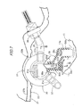
- Fig. 2 is a view when being viewed from the arrow 2 in Fig. 1 .
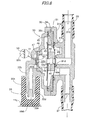
- Fig. 3 is an enlarged cross sectional view taken along line 3-3 in Fig. 1 .
- Fig. 4 is a view when being viewed from the arrow 4 in Fig. 3 .
- Fig. 5 is an enlarged cross sectional view taken along line 5-5 in Fig. 4 .
- Fig. 6 is an enlarged cross sectional view taken along line 6-6 in Fig. 2 .
- Fig. 7 is an enlarged cross sectional view taken along line 7-7 in Fig. 6 .
- Fig. 1 is a front view of a general purpose engine.
- Fig. 2 is a view when being viewed from the arrow 2 in Fig. 1 .
- Fig. 3 is an enlarged cross sectional view taken along line 3-3
- Fig. 8 is an enlarged cross sectional view taken along line 8-8 in Fig. 7 .
- Fig. 9 is an enlarged cross sectional view taken along line 9-9 in Fig. 6 and Fig. 10.
- Fig. 10 is an enlarged cross sectional view taken along line 10-10 in Fig. 2 .
- Fig. 11 is a partial view of Fig. 10 .
- Fig. 12 is a cross sectional view taken along line 12-12 in Fig. 10 .
- a cylinder head 12 and a head cover 13 are arranged so as to be raised in relation to an engine case 11 having a crank case and a cylinder block as one unit with a cylinder axis line L slightly tilted.
- the crank shaft 14 is projected from an end surface of the engine case 11, and a recoil starter 16 for cranking and starting the crank shaft 14 is provided on an outer surface of a cover 15 which covers another end surface of the engine case 11.
- a carburetor 17 is provided at the side of the cylinder head 12, and an intake passage 18 extending upward from the carburetor 17 is connected to an air cleaner 19.
- a muffler 20 is attached so as to align with the air cleaner 19 above the cylinder head 12 and the head cover 13, and a fuel tank 21 is attached nearer the crank case than the air cleaner 19 and the muffler 20.
- the fuel tank 21 is constituted in such a way that a lower edge of a tank upper 21a, an upper edge of a tank lower 21b and an upper edge of a tank holder 22 are combined as one unit by a caulking part 23.
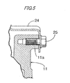
- a tank stay 24 is fixed to four attachment bosses 11a projected on the engine case 11 with bolts 25, and outer circumference parts of four rubber bushes 26 are supported by an upper surface of the tank stay 24.
- a bolt 27 penetrating frombelow to above of the center of each rubber bush 26 penetrates the tank holder 22 and a reinforcing plate 28 to be engaged with a nut 29, and thus the fuel tank 21 is supported above the engine case 11 without vibration.
- an auto fuel cock 30 for automatically feeding fuel in the fuel tank 21 to the carburetor 17 during the operation of the engine E is attached to a lower surface of the fuel tank 21.
- the auto fuel cock 30 includes a first housing 31 and a second housing 32 combined as one unit, and a stay 31a (see Fig. 6 ) projected from the first housing 31 is fixed to a lower surface of the tank holder 22 with a bolt 33 and a nut 34.
- an upper part of the auto fuel cock 30 is projected upward through an opening 22a (see Fig. 7 ) of the tank holder 22, and a lower part of the auto fuel cock 30 is projected downward through an opening 24a (see Figs. 3 and 6 ) of the tank stay 24.
- the first housing 31 of the auto fuel cock 30 includes: a fuel entrance joint 31b; a fuel exit joint 31c; a valve seat 31d formed between the fuel entrance joint 31b and the fuel exit joint 31c; and a disc-shaped diaphragm supporting part 31e.
- the second housing 32 includes: a first negative pressure introduction joint 32a; a negative pressure chamber 32b communicating with the first negative pressure introduction joint 32a; and a disc-shaped diaphragm supporting part 32c.
- the fuel entrance joint 31b is connected to a joint 36 provided on the lower surface of the fuel tank 21 via a first fuel hose 35
- the fuel exit joint 31c is connected to the carburetor 17 via a second fuel hose 37
- the first negative pressure introduction joint 32a is connected to a secondnegative pressure introduction joint 11b of the engine case 11 via a negative pressure tube 38 made of rubber. Since the negative pressure tube 38 made of rubber is employed, the degree of freedom of lay-out of the fuel tank 21 to the engine case 11 can be raised.
- a ring-shaped diaphragm supporting member 39 is held between the diaphragm supporting part 31e of the first housing 31 and the diaphragm supporting part 32c of the second housing 32.
- An outer circumference part of a first diaphragm 40 is fixed between the diaphragm supporting part 31e of the first housing 31 and the diaphragm supporting member 39 via a sealing member 41.
- the outer circumference part of a second diaphragm 42 is fixed between the diaphragm supporting part 32c of the second housing 32 and the diaphragm supporting member 39 via a sealing member 43.
- the first and second diaphragms 40 and 42, a spacer block 44 held between the center parts of the first and second diaphragms 40 and 42 and a disc-shaped spring sheet 45 brought into contact with a rear surface of the second diaphragm 42 are fixed as one unit with a rivet 46 penetrating them.
- a valve seat forming member 48 is fitted between the first negative pressure introduction joint 32a of the second housing 32 and the negative pressure chamber 32b via a spacer plate 47.
- a valve body 40a formed on the center part of the first diaphragm 40 is energized in a direction to which the valve body 40a formed at the center of the first diaphragm 40 is seated on the valve seat 31d of the first housing 31 seat 31d of the first housing 31 with a valve spring 49 arranged between the valve seat forming member 48 and the spring sheet 45.
- An end of a reed valve 50 capable of sitting down on a valve seat 48b facing a through hole 48a penetrating the center part of the valve seat forming member 48 and an end of a stopper 51 for regulating the movable range of the reed valve 50 by covering the outer side thereof are fixed to the valve seat forming member 48 with a bolt (not shown).
- a fine through hole 50a for making the first negative pressure introduction joint 32a communicate with the negative pressure chamber 32b is formed in the reed valve 50.
- a taper part 32d is formed at a lower end of the first negative pressure introduction joint 32a so that the negative pressure tube 38 can be easily inserted into the introduction joint 32a, and a reverse U-shaped notch 32e is formed on the taper part 32d.
- the negative pressure tube 38 includes: a first connection part 38a which vertically extends and is inserted into the first negative pressure introduction joint 32a; a second connection part 38b which vertically extends and is inserted into the second negative pressure introduction joint 11b; and a middle part 38c which obliquely extends downward from a lower end of the first connection part 38a to an upper end of the second connection part 38b, and is formed in an approximate crank shape.
- a linear recessed part 38d is formed on a bottom surface of the first connection part 38a.
- a linear projection 11c which fits into the linear recessed part 38d is formed on an upper surface of the engine case 11 facing the bottom surface of the first connection part 38a of the negative pressure tube 38, and the negative pressure tube 38 is positioned in a rotational direction around a vertical axis by engagement of the recessed part 38d and the projection 11c.
- a breathing unit 52 provided on the side of the engine case 11 includes a breather chamber 54 surrounded by a ring-shaped circumference wall 11d and a cover 53, and a breather passage 11e is opened at an end of the breather chamber 54.
- An end of a reed valve 55 capable of being seated down on a valve seat 11f formed at an opening part of the breather passage 11e and an end of a stopper 56 for regulating the movable range of the reed valve 55 are fixed to an inner wall of the breather chamber 54 with a bolt 57.
- a joint 53a is formed on the cover 53 so as to face another end of the breather chamber 54 far from the breather passage 11e, and is connected to an intake system of the engine E via a breather pipe 58.
- Two ribs 11g, 11h are projected in the breather chamber 54 in order to constitute a labyrinth 59 between the breather passage 11e and the joint 53a.
- a bottom part of the breather chamber 54 communicates with an inner space of the engine case 11 via an oil return hole 11i.
- a pin part 14a of the crank shaft 14 of the engine E is connected to a piston 63 via a connecting rod 62.
- a journal part 14b of the crank shaft 14 is supported by the engine case 11 via a ball bearing 64.
- Another journal part 14c of the crank shaft 14 is supported by a bearing holder 66, which is fixed in the engine case 11 with six bolts 65, via a ball bearing 67.
- a covering member 68 is fixed to an opening 11k of the engine case 11 so as to cover a front surface of the bearing holder 66 with nine bolts 69, and an oil agitating chamber 70 is formed between the covering member 68 and the bearing holder 66.
- both ends of a first balancer shaft 73 are supported between the engine case 11 and the bearing holder 66 via a pair of ball bearings 71 and 72.
- a driving gear 74 provided on the crank shaft 14 is engaged with a driven gear 75 provided on the first balancer shaft 73 so that the first balancer shaft 73 rotates at the same number of rotations as that of the crank shaft 14.
- a rotor 77 is rotatably supported by-a bottom part of the oil agitating chamber 70 via a rotor shaft 76.
- a driven gear 78 provided on the rotor shaft 76 is engaged with a driving gear 79 provided on the crank shaft 14 so that the rotor 77 is rotationally driven by the crank shaft 14.
- a timing belt 81 wound around a driving sprocket 80 provided on the crank shaft 14 is connected to a driven sprocket (not shown) provided on the cylinder head 12.
- the oil agitating chamber 70 is a region surrounded by the first to fourth ribs 66a to 66d of the bearing holder 66.
- a gas-liquid separating chamber 83 having a labyrinth 82 constituted by the fourth and fifth ribs 66d and 66e of the bearing holder 66 and the first and second ribs 68a and 68b of the cover member 68 is formed outside of the first to fourth ribs 66a to 66d.
- An upper part of the gas-liquid separating chamber 83 is made to communicate with the breathing unit 52 via the breather passage 11e (see Fig. 9 ).
- Air including oil mist generated in the oil agitating chamber 70 pass through the labyrinth 82 constituted by the fourth and fifth ribs 66d and 66e of the bearing holder 66 and the first and second ribs 68a and 68b of the cover member 68 in the gas-liquid separating chamber 83, and the oil separated during the passage falls along the first and second ribs 66a and 66b to be returned to the bottom part of the oil agitating chamber 70.
- the bearing holder 66 which includes the ball bearing 67 for supporting the crank shaft 14 is fixed so as to face the opening 11k of the engine case 11, and the gas-liquid separating chamber 83 is formed between the cover member 68 combined with the opening 11k and the bearing holder 66, the bearing holder 66 can be used as a part of a wall surface of the gas-liquid separating chamber 83.
- the number of parts can be increased compared with a case where a part of the wall surface of the gas-liquid separating chamber 83 is constituted by a specific member, and miniaturization, lightening, simplification of the shape of the engine case 11 can be realized compared with a case where a part of the side wall of the gas-liquid separating chamber 83 is constituted by a partition wall integrally formed with the engine case 11.
- the labyrinth 82 is provided in the gas-liquid separating chamber 83, the oil mist included in the air in the engine case 11 can be effectively separated.
- the labyrinth 82 is constituted in such a way that the fourth and fifth ribs 66d and 66e projecting from the bearing holder 66 side are mutually overlapped with the first and second ribs 68a and 68b projected from the cover member 68 by the distance ⁇ (see Fig. 9 ), and therefore the complicated labyrinth 82 is constituted with a simple structure and a gas-liquid separation effect can be further raised.
- the air from which the oil caulking removed in the labyrinth 82 of the gas-liquid separating chamber 83 passes through the reed valve 55 of the breather passage 11e and the breathing unit 52, and is fed to the breather chamber 54. That is, the pressure pulsation generated in accordance with reciprocation of the piston 63 is transmitted to the breather passage 11e, and the reed valve 55 is opened when the pressure in the breather passage 11e becomes positive pressure, or is shut when the pressure therein becomes negative pressure, by which, the air in the breather passage 11e is fed to the breather chamber 54.
- the air, from which the oil mist is separated by the gas-liquid separating unit 61, is introduced to the breathing unit 52 via the breather passage 11e and further subjected to the gas-liquid separation. Therefore, the consumption amount of oil can be further reduced.
- the air, from which the oil caulking thus separated still includes fuel vapor which blows from a combustion room to the inside of the engine case 11, the air including the fuel vapor is returned to the intake system of the engine E through the joint 53a of the cover 53 and the breather pipe 58, and prevented from diffusing into the atmosphere by combustion of the fuel vapor and air-fuel mixture.
- the pressure pulsation in the engine case 11 is transmitted to the first negative pressure introduction joint 32a of the auto fuel cock 30 through the breather passage 11e, the communication hole 11j and the negative pressure tube 38.
- the reed valve 50 goes away from the valve seat 48b and the pressure in the negative pressure chamber 32b becomes negative pressure.
- the reed valve 50 sits down on the valve seat 48b and the negative pressure in the negative pressure chamber 32b is maintained.
- the first and second diaphragms 40 and 42 move left (in Fig. 8 ) against elastic force of the valve spring 49 and the valve body 40a formed on the first diaphragm 40 goes away from the valve seat 31d.
- the fuel in the fuel tank 21 is fed to the carburetor 17 via the first fuel hose 35, the fuel entrance joint 31b, a gap between the valve seat 31d and the valve body 40a, the fuel exit joint 31c and the second fuel hose 37.
- the first and second diaphragms 40 and 42 are energized in a right direction (in Fig. 8 ) by the elastic force of the valve spring 49 when the engine E stops and the pressure pulsation in the breather passage 11e disappears, and therefore the reed valve 50 suctioned in the right direction sits down on the valve seat 48b so that the negative pressure chamber 32b is sealed.
- the valve body 40a sits down on the valve seat 31d by the elastic force of the valve spring 49 and the auto fuel cock is shut. Therefore, the fuel feed from the fuel tank 21 to the carburetor 17 can be automatically stopped with the stopping of the engine E.
- the combinations of the negative pressure tube 38 and the first and second negative pressure introduction joints 32a and 11b are performed in accordance with the following steps. That is, the tank stay 24 is previously assembled to the tank holder 22 of the fuel tank 21 via the rubber bushes 26, and the first fuel hose 35 is previously assembled to the auto fuel cock 30.
- the second connection part 38b of the negative pressure tube 38 is previously fitted onto the second negative pressure introduction joint 11b of the engine case 11.
- the recessed part 38d on the bottom surface of the first connection part 38a of the negative pressure tube 38 is engaged with the projection 11c of the engine case 11 (see Fig. 7 ) so that the negative pressure tube 38 can be positioned in the rotation direction.
- the fuel tank 21 is made to approach the engine case 11 from above in this state, the first negative pressure introduction joint 32a of the auto fuel cock 30 is fitted into the first connection part 38a of the negative pressure tube 38, and thereafter the tank stay 24 is fitted to the engine case 11 with the bolts 25. Then, the second fuel hose 37 communicating with the carburetor 17 is fitted onto the fuel exit joint 31c and the attachment is completed.
- the pressure pulsation in the breather passage 11e cannot be transmitted to the negative pressure chamber 32b of the auto fuel cock 30 and there is a possibility that a malfunction of the auto fuel cock 30 occurs.
- the air, from which almost the oil caulking removed by the gas-liquid separating unit 61, is fed to the breather passage 11e, and the pressure pulsation in the breather passage 11e is introduced into the auto fuel cock 30. Therefore, the malfunction of the auto fuel cock 30 caused by the oil mist can be previously prevented.
- the breather passage 11e for feeding the air passed through the gas-liquid separating unit 61 to the breathing unit 52 is provided at an upper part of the engine case 11, infiltration of the oil mist into the breather passage 11e can be further effectively prevented.
- the auto fuel cock 30 is made to operate with use of the pressure pulsation in the breather passage 11e, it is unnecessary to form the specificpassage for transmitting the pressure pulsation to the auto fuel cock 30.
- the negative pressure tube 38 includes the first connection part 38a which vertically extends and is inserted into the first negative pressure introduction joint 32a, the second connection part 38b which vertically extends and is inserted into the second negative pressure introduction joint 11b, and the middle part 38c which obliquely extends downward from the lower end of the first connection part 38a to the upper end of the second connection part 38b. Therefore, even if the oil mist infiltrates into the negative pressure tube 38, the oil caulking discharged to the breather passage 11e by gravity without accumulating in the negative pressure tube 38, and a situation where the pressure pulsation is not transmitted to the auto fuel cock 30 can be previously avoided.
- the taper part 32d is formed at the lower end of the first negative pressure introduction joint 32a of the auto fuel cock 30, insertion work of the first negative pressure introduction joint 32a into the first connection part 38a of the negative pressure tube 38 becomes easy.
- the notch 32e is formed on the taper part 32d, the action of the notch 32e can prevent the first negative pressure introduction joint 32a from being closed even if the oil is accumulated on the lower end of the first connection part 38a as shown being circled by the chain line in Fig. 7 when the engine E is tilted.
- the notch 32e is opened toward the middle part 38c side of the negative pressure tube 38, the notch 32e can be further reliably prevented from sinking beneath the oil.
- the auto fuel cock 30 since the auto fuel cock 30 operates by the negative pressure of the engine case 11 which is stronger than intake negative pressure of the engine E, the sufficient negative pressure is generated only by cranking by the recoil starter 16 and the fuel can be fed to the carburetor 17.
- the auto fuel cock 30 can be reliably made to operate by employment of the first and second diaphragms 40 and 42 even if the negative pressure is small.
- the recessed part 38d provided on the negative pressure tube 38 and the projection 11c provided on the engine case 11 have been exemplified as a positioning part in the exemplary embodiment, the positional relationship between the recessed part and the projection may be reversible, and any shapes of the recessed part and the projection are applicable.
- the present invention is applicable to a fuel feed system of an engine in which an auto fuel cock for controlling fuel feed from a fuel tank to the engine is operated by pressure pulsation of air in an engine case.
- the present invention is applicable to a fuel feed system of an engine in which an auto fuel cock is arranged between an engine case and a fuel tank fixed above the engine case, and in which an inside of the engine case is connected to the auto fuel cock via a negative pressure tube.
Abstract
Description
- The present invention relates to a fuel feed system of an engine in which an auto fuel cock for controlling fuel feed from a fuel tank to the engine is operated by pressure pulsation of air in an engine case.
- Additionally, the present invention relates to a fuel feed system of an engine in which an auto fuel cock is arranged between an engine case and a fuel tank fixed above the engine case, and in which an inside of the engine case is connected to the auto fuel cock via a negative pressure tube.
- Disclosed in
JP-A-2003-171910 - Disclosed in
JP-U-61-097577 - Additionally, disclosed in
JP-Y-59-013336 - In an apparatus of
JP-A-2003-171910 - Additionally, in an apparatus of
JP-U-61-097577 - On the other hand, when an auto fuel cock is arranged between an engine case and a fuel tank fixed above the engine case and the inside of the engine case is connected to the auto fuel cock via a negative pressure tube, there is a problem that work for connecting a lower end of the negative pressure tube to the inside of the engine case and for connecting an upper end of the negative pressure tube to the auto fuel cock is necessary and therefore much labor and time are required for the work. In particular, the above work becomes more difficult in a case where a working space between the fuel tank and the engine case is small. The distance between the engine case and the fuel tank increases when sufficient space is ensured, and thus there exists a problem the whole engine enlarges.
- Additionally, it is conceived that a negative pressure introduction joint of the auto fuel cock fixed to a lower surface of the fuel tank to a negative pressure introduction joint of the engine case via an approximate crank-shaped is a bent negative pressure tube so that the whole engine is miniaturized by shortening the distance between the engine case and the fuel tank fixed above the engine case. However, this causes a possibility that oil which infiltrates from the engine case accumulates at a bent part of the negative pressure tube when the engine is tilted. When a tip of the negative pressure introduction joint of the auto fuel cock is soaked into the oil, there is a possibility that the operation of the auto fuel cock, of which the communication with the inside of the engine case is cut off, becomes impossible.
- A first object of the present invention is to provide a fuel feed system of an engine for preventing a malfunction of an auto fuel cock caused by an infiltration of oil from an engine case.
- A second object of the present invention is to provide a fuel feed system of an engine in which work for connecting an inside of an engine case to an auto fuel cock via an negative pressure tube is easy without increasing a distance between the engine case and a fuel tank.
- A third object of the present invention is to provide a fuel feed system of an engine in which a negative pressure tube for connecting a negative pressure introduction joint of an auto fuel cock fixed to a lower surface of a fuel tank to the negative pressure introduction joint of an engine case is not blocked due to the oil.
- In accordance with one or more embodiments of the present invention, a fuel feed system of an engine in which an auto fuel cock for controlling fuel feed from a fuel tank to the engine is operated by pressure pulsation of air in an engine case is providedwith a gas-liquid separating unit for separating oil mist generated in the engine case from air. The auto fuel cock is operated by the pressure pulsation of the air from which the oil mist is separated by the gas-liquid separating unit.
- The fuel feed system may include a breather passage for feeding the air from which the oil mist is separated by the gas-liquid separating unit to a breathing unit and makes the breather passage communicate with the auto fuel cock.
- In the above fuel feed system, the breather passage may be arranged at an upper part of the engine case.
- In the above fuel feed system, a first negative pressure introduction j oint provided on the auto fuel cockmaybe connected to a second negative pressure introduction joint provided on the breather passage via the negative pressure tube.
- In the above fuel feed system, the negative pressure tube may be monotonously tilted downward from the first negative pressure introduction joint to the second negative pressure introduction joint.
- In accordance with one or more embodiments of the present invention, a fuel feed system of an engine is provided with: an engine case; a fuel tank fixed above an engine case; an auto fuel cock which is arranged between the engine case and the fuel tank and fixed to a lower surface of the fuel tank; and a negative pressure tube connecting an inside of the engine case to the auto fuel cock. The auto fuel cock has a first negative pressure introduction joint projected downward, the engine case has a second negative pressure introduction joint projected upward from an upper surface of the engine case. The negative pressure tube has a first connection part fitted onto the first negative pressure introduction joint and a second connection part fitted onto the second negative pressure introduction joint. The negative pressure tube is positioned so that the first connection part of the negative pressure tube, of which the second connection part is fitted onto the second negative pressure introduction joint, is located on a movement route of the first negative pressure introduction joint of the auto fuel cock when the fuel tank, to which the auto fuel cock is fixed, is moved downward to be fixed above the engine case.
- In the fuel feed system, a positioning part for regulating an attachment posture of the negative pressure tube to the engine case may be provided between the negative pressure tube and the engine case.
- In the above fuel feed system, the positioning part may have a recessed part provided on the negative pressure tube and a projection provided on the engine case. Alternatively, the positioning part may have a projection provided on the negative pressure tube and a recessed part provided on the engine case.
- In the above fuel feed system, a taper part of which the outer diameter is reduced downward may be formed at a lower end of the first negative pressure introduction joint of the auto fuel cock.
- In the above fuel feed system, the negative pressure tube may be monotonously tilted downward from the first negative pressure introduction joint to the second negative pressure introduction joint.
- Further, a projection and a recessed part of the exemplary embodiment described below correspond to the positioning part of the present invention.
- In the above fuel feed system, the negative pressure tube may have a middle part between the first connection part and the second connection part and be formed in an approximate crank shape, and the first negative pressure introduction joint may have a notch at the lower end thereof.
- In the above fuel feed system, the notch of the first negative pressure introduction joint may be opened toward the middle part side of the negative pressure tube.
- The above fuel feed system may include the gas-liquid separating unit for separating the oil mist generated in the engine case from the air and make the auto fuel cock operate by the pressure pulsation of the air from which the oil mist is separated by the gas-liquid separating unit.
- The above fuel feed systemmay include the breather passage for feeding the air from which the oil mist is separated by the gas-liquid separating unit to the breathing unit and makes the breather passage communicate with the auto fuel cock.
- In the above fuel feed system, the breather passage may be arranged at the upper part of the engine case.
- According to one or more embodiments of the present invention, a fuel feed system is provided with the gas-liquid separating unit for separating oil mist generated in the engine case from air and the auto fuel cock is operated by pressure. pulsation of the air from which the oil mist is separated by the gas-liquid separating unit. Thereby, infiltration of the oil mist into the auto fuel cock can be suppressed to the minimum and a malfunction of the auto fuel cock caused by accumulation of the oil can be prevented.
- Additionally, a breather passage for feeding the air from which the oil mist is separated by the gas-liquid separating unit to a breathing unit is connected to the auto fuel cock.
Thus, it is unnecessary to provide a specific passage for transmitting the pressure pulsation of the air in the engine case to the auto fuel cock. - Additionally, the breather passage is arranged at an upper part of the engine case. Thus, the oil mist, which has not been completely removed and infiltrates into the breather passage, can be suppressed to the minimum.
- Additionally, a first negative pressure introduction joint provided on the auto fuel cock is connected to a second negative pressure introduction joint provided on the breather passage via the negative pressure tube. Thus, the degree of freedom of an attachment position of the auto fuel cock can be raised.
- Additionally, the negative pressure tube is monotonously tilted downward from the first negative pressure introduction joint to the second negative pressure introduction joint. Thus, the oil in the negative pressure tube is discharged to the breather passage by gravity and canbe more reliably prevented from infiltrating into the auto fuel cock.
- According to one or more embodiments of the present invention, when the fuel tank, to which the auto fuel cock is fixed, is moved downward so as to be fixed above the engine case, the first negative pressure introduction joint of the auto fuel cock is automatically fitted into a first connection part of the negative pressure tube, of which a second connection part is previously fitted onto the second negative pressure introduction j oint of the engine case. Thus, it becomes possible to simultaneously complete attachment of the fuel tank and attachment of the negative pressure tube, and work efficiency is greatly improved. Further, since it is unnecessary to provide a working space, where the first and second connection parts of the negative pressure tube are respectively fitted onto the first and second negative pressure introduction joints, between a lower surface of the fuel tank and an upper surface of the engine case, the fuel tank is made to approach the engine case as much as possible so that the whole engine can be miniaturized.
- Additionally, the positioning part for regulating an attachment posture of the negative pressure tube to the engine case is provided between the negative pressure tube and the engine case. Thus, the first negative pressure introduction joint of the auto fuel cock can be easily fitted into the first connection part of the negative pressure tube.
- Additionally, the positioning part is constituted by a recessed part provided on the negative pressure tube and a projection provided on the engine case. Alternatively, the positioning part is constituted by a projection provided on the negative pressure tube and a recessed part provided on the engine case. Thus, the attachment posture of the negative pressure tube to the engine case can be easily and reliably regulated by engaging the projection with the recessed part.
- Additionally, a taper part, of which the outer diameter is reduced downward, is provided at a lower end of the first negative pressure introduction joint of the auto fuel cock.
Thus, the first negative pressure introduction joint of the auto fuel cock can be easily fitted into the first connection part of the negative pressure tube when the fuel tank is moved downward so as to be fixed above the engine case. - Additionally, the negative pressure tube is monotonously tilted downward from the first negative pressure introduction joint to the second negative pressure introduction joint. Thus, the oil infiltrating into the negative pressure tube is discharged by gravity, and can be reliably prevented from infiltrating into the auto fuel cock.
- Additionally, the negative pressure tube has a middle part between the first connection part and the second connection part and is formed in an approximate crank shape, and the first negative pressure introduction joint has a notch at the lower end thereof. Thus, even if the engine is tilted so that the first connection part side of the middle part of the negative pressure tube is lowered and even if the oil is accumulated at the corners of the middle part and the first connection part, the auto fuel cock can be made to operate without any trouble so long as the notch formed at the lower end of the first negative pressure introduction joint is not soaked into the oil. That is why communication of the inside of the engine case and the auto fuel cock is not cut off.
- Additionally, the notch of the first negative pressure introduction joint is opened toward the middle part side of the negative pressure tube. Thus, the notch can be hardly soaked into the oil even if the oil is accumulated at the corners of the middle part and the first connection part of the negative pressure tube.
- Additionally, the gas-liquid separating unit for separating the oil mist generated in the engine case from the air is provided, and the auto fuel cock is made to operate by the pressure pulsation of the air from which the oil mist is separated by the gas-liquid separating unit. Thus, the infiltration of the oil mist into the auto fuel cock is suppressed to the minimum, and the malfunction of the auto fuel cock caused by the accumulation of the oil can be prevented.
- Additionally, the breather passage for feeding the air from which the oil mist is separated by the gas-liquid separating unit to the breathing unit is made to communicate with the auto fuel cock. Thus, it is unnecessary to provide the specific passage for transmitting the pressure pulsation of the air in the engine case to the auto fuel cock.
- Additionally, the breather passage is arranged at the upper part of the engine case. Thus, the oil mist, which has not been completely removed and infiltrates into the breather passage, can be suppressed to the minimum.
- Other aspects and advantages of the invention will be apparent from the following description and the appended claims.
-
-
Fig. 1 is a front view of a general purpose engine. -
Fig. 2 is a view when being viewed from thearrow 2 inFig. 1 . -
Fig. 3 is an enlarged cross sectional view taken along line 3-3 inFig. 1 . -
Fig. 4 is a view when being viewed from thearrow 4 inFig. 3 . -
Fig. 5 is an enlarged cross sectional view taken along line 5-5 inFig. 4 . -
Fig. 6 is an enlarged cross sectional view taken along line 6-6 inFig. 2 . -
Fig. 7 is an enlarged cross sectional view taken along line 7-7 inFig. 6 . -
Fig. 8 is an enlarged cross sectional view taken along line 8-8 inFig. 7 . -
Fig. 9 is an enlarged cross sectional view taken along line 9-9 inFig. 6 orFig. 10 . -
Fig. 10 is an enlarged cross sectional view taken along line 10-10 inFig. 2 . -
Fig. 11 is a partial view ofFig. 10 . -
Fig. 12 is a cross sectional view taken along line 12-12 inFig. 10 . -
- 11
- engine case
- 11b
- second negative pressure introduction joint
- 11c
- projection
- 11e
- breather passage
- 21
- fuel tank
- 30
- auto fuel cock
- 32a
- first negative pressure introduction joint
- 32d
- taper part
- 32e
- notch
- 38
- negative pressure tube
- 38a
- first connection part
- 38b
- second connection part
- 38c
- middle part
- 38d
- recessed part
- 52
- breathing unit
- 61
- gas-liquid separating unit
- E
- engine
- Exemplary embodiments of the present invention will be described hereinafter with reference to the accompanying drawings.
-
Figs. 1 to 12 show an exemplary embodiment of the present invention.Fig. 1 is a front view of a general purpose engine.Fig. 2 is a view when being viewed from thearrow 2 inFig. 1 .Fig. 3 is an enlarged cross sectional view taken along line 3-3 inFig. 1 .Fig. 4 is a view when being viewed from thearrow 4 inFig. 3 .Fig. 5 is an enlarged cross sectional view taken along line 5-5 inFig. 4 .Fig. 6 is an enlarged cross sectional view taken along line 6-6 inFig. 2 .Fig. 7 is an enlarged cross sectional view taken along line 7-7 inFig. 6 .Fig. 8 is an enlarged cross sectional view taken along line 8-8 inFig. 7 .Fig. 9 is an enlarged cross sectional view taken along line 9-9 inFig. 6 andFig. 10. Fig. 10 is an enlarged cross sectional view taken along line 10-10 inFig. 2 .Fig. 11 is a partial view ofFig. 10 .Fig. 12 is a cross sectional view taken along line 12-12 inFig. 10 . - As shown in
Fig. 1 andFig. 2 , in a single cylinder four cycle engine E, acylinder head 12 and ahead cover 13 are arranged so as to be raised in relation to anengine case 11 having a crank case and a cylinder block as one unit with a cylinder axis line L slightly tilted. Thecrank shaft 14 is projected from an end surface of theengine case 11, and arecoil starter 16 for cranking and starting thecrank shaft 14 is provided on an outer surface of acover 15 which covers another end surface of theengine case 11. Acarburetor 17 is provided at the side of thecylinder head 12, and anintake passage 18 extending upward from thecarburetor 17 is connected to anair cleaner 19. Amuffler 20 is attached so as to align with theair cleaner 19 above thecylinder head 12 and thehead cover 13, and afuel tank 21 is attached nearer the crank case than theair cleaner 19 and themuffler 20. - The
fuel tank 21 is constituted in such a way that a lower edge of a tank upper 21a, an upper edge of a tank lower 21b and an upper edge of atank holder 22 are combined as one unit by acaulking part 23. Atank stay 24 is fixed to fourattachment bosses 11a projected on theengine case 11 withbolts 25, and outer circumference parts of fourrubber bushes 26 are supported by an upper surface of thetank stay 24. Abolt 27 penetrating frombelow to above of the center of eachrubber bush 26 penetrates thetank holder 22 and a reinforcingplate 28 to be engaged with anut 29, and thus thefuel tank 21 is supported above theengine case 11 without vibration. - As shown in
Fig. 3 andFigs. 6 to 8 , anauto fuel cock 30 for automatically feeding fuel in thefuel tank 21 to thecarburetor 17 during the operation of the engine E is attached to a lower surface of thefuel tank 21. Theauto fuel cock 30 includes afirst housing 31 and asecond housing 32 combined as one unit, and astay 31a (seeFig. 6 ) projected from thefirst housing 31 is fixed to a lower surface of thetank holder 22 with abolt 33 and anut 34. Here, an upper part of theauto fuel cock 30 is projected upward through anopening 22a (seeFig. 7 ) of thetank holder 22, and a lower part of theauto fuel cock 30 is projected downward through anopening 24a (seeFigs. 3 and6 ) of thetank stay 24. - As most clearly shown in
Fig. 8 , thefirst housing 31 of theauto fuel cock 30 includes: a fuel entrance joint 31b; a fuel exit joint 31c; avalve seat 31d formed between the fuel entrance joint 31b and the fuel exit joint 31c; and a disc-shapeddiaphragm supporting part 31e. Additionally, thesecond housing 32 includes: a first negative pressure introduction joint 32a; anegative pressure chamber 32b communicating with the first negative pressure introduction joint 32a; and a disc-shapeddiaphragm supporting part 32c. The fuel entrance joint 31b is connected to a joint 36 provided on the lower surface of thefuel tank 21 via afirst fuel hose 35, the fuel exit joint 31c is connected to thecarburetor 17 via asecond fuel hose 37, and the first negative pressure introduction joint 32a is connected to a secondnegative pressure introduction joint 11b of theengine case 11 via anegative pressure tube 38 made of rubber. Since thenegative pressure tube 38 made of rubber is employed, the degree of freedom of lay-out of thefuel tank 21 to theengine case 11 can be raised. - A ring-shaped diaphragm supporting member 39 is held between the
diaphragm supporting part 31e of thefirst housing 31 and thediaphragm supporting part 32c of thesecond housing 32. An outer circumference part of afirst diaphragm 40 is fixed between thediaphragm supporting part 31e of thefirst housing 31 and the diaphragm supporting member 39 via a sealing member 41. The outer circumference part of asecond diaphragm 42 is fixed between thediaphragm supporting part 32c of thesecond housing 32 and the diaphragm supporting member 39 via a sealingmember 43. The first andsecond diaphragms spacer block 44 held between the center parts of the first andsecond diaphragms spring sheet 45 brought into contact with a rear surface of thesecond diaphragm 42 are fixed as one unit with arivet 46 penetrating them. - A valve
seat forming member 48 is fitted between the first negative pressure introduction joint 32a of thesecond housing 32 and thenegative pressure chamber 32b via aspacer plate 47. A valve body 40a formed on the center part of thefirst diaphragm 40 is energized in a direction to which the valve body 40a formed at the center of thefirst diaphragm 40 is seated on thevalve seat 31d of thefirst housing 31seat 31d of thefirst housing 31 with avalve spring 49 arranged between the valveseat forming member 48 and thespring sheet 45. An end of areed valve 50 capable of sitting down on a valve seat 48b facing a throughhole 48a penetrating the center part of the valveseat forming member 48 and an end of astopper 51 for regulating the movable range of thereed valve 50 by covering the outer side thereof are fixed to the valveseat forming member 48 with a bolt (not shown). A fine throughhole 50a for making the first negative pressure introduction joint 32a communicate with thenegative pressure chamber 32b is formed in thereed valve 50. - As clearly shown in
Fig. 7 andFig. 8 , ataper part 32d is formed at a lower end of the first negative pressure introduction joint 32a so that thenegative pressure tube 38 can be easily inserted into the introduction joint 32a, and a reverseU-shaped notch 32e is formed on thetaper part 32d. Thenegative pressure tube 38 includes: afirst connection part 38a which vertically extends and is inserted into the first negative pressure introduction joint 32a; asecond connection part 38b which vertically extends and is inserted into the second negative pressure introduction joint 11b; and amiddle part 38c which obliquely extends downward from a lower end of thefirst connection part 38a to an upper end of thesecond connection part 38b, and is formed in an approximate crank shape. A linear recessedpart 38d is formed on a bottom surface of thefirst connection part 38a. On the other hand, alinear projection 11c which fits into the linear recessedpart 38d is formed on an upper surface of theengine case 11 facing the bottom surface of thefirst connection part 38a of thenegative pressure tube 38, and thenegative pressure tube 38 is positioned in a rotational direction around a vertical axis by engagement of the recessedpart 38d and theprojection 11c. - As clearly shown in
Fig. 6 andFig. 9 , abreathing unit 52 provided on the side of theengine case 11 includes abreather chamber 54 surrounded by a ring-shapedcircumference wall 11d and acover 53, and abreather passage 11e is opened at an end of thebreather chamber 54. An end of areed valve 55 capable of being seated down on a valve seat 11f formed at an opening part of thebreather passage 11e and an end of astopper 56 for regulating the movable range of thereed valve 55 are fixed to an inner wall of thebreather chamber 54 with abolt 57. A joint 53a is formed on thecover 53 so as to face another end of thebreather chamber 54 far from thebreather passage 11e, and is connected to an intake system of the engine E via abreather pipe 58. Tworibs breather chamber 54 in order to constitute alabyrinth 59 between thebreather passage 11e and the joint 53a. A bottom part of thebreather chamber 54 communicates with an inner space of theengine case 11 via anoil return hole 11i. Additionally, acommunication hole 11j penetrating the inside of the second negative pressure introduction joint 11b, onto which thesecond connection part 38b of thenegative pressure tube 38 is fitted, communicates with thebreather passage 11e. - Next, the construction of a gas-
liquid separating unit 61 of the engine E will be described with reference toFigs. 9 to 12 . - A
pin part 14a of thecrank shaft 14 of the engine E is connected to apiston 63 via a connectingrod 62. Ajournal part 14b of thecrank shaft 14 is supported by theengine case 11 via aball bearing 64. Anotherjournal part 14c of thecrank shaft 14 is supported by a bearingholder 66, which is fixed in theengine case 11 with sixbolts 65, via aball bearing 67. A coveringmember 68 is fixed to anopening 11k of theengine case 11 so as to cover a front surface of the bearingholder 66 with ninebolts 69, and anoil agitating chamber 70 is formed between the coveringmember 68 and the bearingholder 66. - Moreover, both ends of a first balancer shaft 73 (see
Fig. 12 ) are supported between theengine case 11 and the bearingholder 66 via a pair ofball bearings driving gear 74 provided on thecrank shaft 14 is engaged with a drivengear 75 provided on thefirst balancer shaft 73 so that thefirst balancer shaft 73 rotates at the same number of rotations as that of thecrank shaft 14. - A rotor 77 is rotatably supported by-a bottom part of the
oil agitating chamber 70 via arotor shaft 76. A drivengear 78 provided on therotor shaft 76 is engaged with adriving gear 79 provided on thecrank shaft 14 so that the rotor 77 is rotationally driven by thecrank shaft 14. Additionally, atiming belt 81 wound around a drivingsprocket 80 provided on thecrank shaft 14 is connected to a driven sprocket (not shown) provided on thecylinder head 12. - As clearly shown in
Fig. 10 andFig. 11 , afirst rib 66a surrounding a part of the outer circumference of the rotor 77, asecondrib 66b surrounding apart of the outer circumferences of thedriving gear 79 and the drivingsprocket 80, athird rib 66c lying to an end of thefirst rib 66a and is parallel with a lower surface of a lower bowstring of thetiming belt 81, afourth rib 66d lying to an end of thesecond rib 66b and is parallel with an upper surface of an upper bowstring of thetiming belt 81, and an independentfifth rib 66e obliquely extending in a direction opposite to an oblique direction of thefourth rib 66d from the vicinity of a connection part of thesecond rib 66b and thefourth rib 66d are projected on the side of the bearingholder 66. Additionally, afirst rib 68a and asecond rib 68b, which are approximately parallel with thefourth rib 66d and thefifth rib 66e of the bearingholder 66 respectively, are projected on the side of thecover member 68. - The
oil agitating chamber 70 is a region surrounded by the first tofourth ribs 66a to 66d of the bearingholder 66. A gas-liquid separating chamber 83 having alabyrinth 82 constituted by the fourth andfifth ribs holder 66 and the first andsecond ribs cover member 68 is formed outside of the first tofourth ribs 66a to 66d. An upper part of the gas-liquid separating chamber 83 is made to communicate with thebreathing unit 52 via thebreather passage 11e (seeFig. 9 ). - Next, action the fuel feed system of the exemplary embodiment of the present invention including the above constitution will be described.
- In
Fig. 10 , when the engine E is operated, the rotor 77 connected to thecrank shaft 14 via thedriving gear 79 and the drivengear 78 rotates in theoil agitating chamber 70, and the oil accumulated on the bottom part of theoil agitating chamber 70 is scrapped up and scattered. The scattered oil is guided between thethird rib 66c and thefourth rib 66d, which are parallel with thetiming belt 81 by the first andsecond ribs holder 66, adhere to thetiming belt 81 and is fed to a valve chamber (not shown) of thecylinder head 12, thereby lubricating a valve mechanism. Air including oil mist generated in theoil agitating chamber 70 pass through thelabyrinth 82 constituted by the fourth andfifth ribs holder 66 and the first andsecond ribs cover member 68 in the gas-liquid separating chamber 83, and the oil separated during the passage falls along the first andsecond ribs oil agitating chamber 70. - Since the bearing
holder 66 which includes theball bearing 67 for supporting thecrank shaft 14 is fixed so as to face theopening 11k of theengine case 11, and the gas-liquid separating chamber 83 is formed between thecover member 68 combined with theopening 11k and the bearingholder 66, the bearingholder 66 can be used as a part of a wall surface of the gas-liquid separating chamber 83. Therefore, the number of parts can be increased compared with a case where a part of the wall surface of the gas-liquid separating chamber 83 is constituted by a specific member, and miniaturization, lightening, simplification of the shape of theengine case 11 can be realized compared with a case where a part of the side wall of the gas-liquid separating chamber 83 is constituted by a partition wall integrally formed with theengine case 11. - In addition, since the
labyrinth 82 is provided in the gas-liquid separating chamber 83, the oil mist included in the air in theengine case 11 can be effectively separated.
In particular, thelabyrinth 82 is constituted in such a way that the fourth andfifth ribs holder 66 side are mutually overlapped with the first andsecond ribs cover member 68 by the distance α (seeFig. 9 ), and therefore thecomplicated labyrinth 82 is constituted with a simple structure and a gas-liquid separation effect can be further raised. - In
Fig. 9 , the air from which the oil caulking removed in thelabyrinth 82 of the gas-liquid separating chamber 83 passes through thereed valve 55 of thebreather passage 11e and thebreathing unit 52, and is fed to thebreather chamber 54. That is, the pressure pulsation generated in accordance with reciprocation of thepiston 63 is transmitted to thebreather passage 11e, and thereed valve 55 is opened when the pressure in thebreather passage 11e becomes positive pressure, or is shut when the pressure therein becomes negative pressure, by which, the air in thebreather passage 11e is fed to thebreather chamber 54. - In
Fig. 6 , the oil, which is included in the air fed to thebreather chamber 54, has not been completely separated from the air by the gas-liquid separating unit 61, is further separated while the air passes through thelabyrinth 59 constituted by theribs engine case 11 through theoil return hole 11i provided on the bottom part of thebreather chamber 54. The air, from which the oil mist is separated by the gas-liquid separating unit 61, is introduced to thebreathing unit 52 via thebreather passage 11e and further subjected to the gas-liquid separation. Therefore, the consumption amount of oil can be further reduced. Although the air, from which the oil caulking thus separated, still includes fuel vapor which blows from a combustion room to the inside of theengine case 11, the air including the fuel vapor is returned to the intake system of the engine E through the joint 53a of thecover 53 and thebreather pipe 58, and prevented from diffusing into the atmosphere by combustion of the fuel vapor and air-fuel mixture. - In
Fig. 9 , the pressure pulsation in theengine case 11 is transmitted to the first negative pressure introduction joint 32a of theauto fuel cock 30 through thebreather passage 11e, thecommunication hole 11j and thenegative pressure tube 38. InFig. 8 , when the pressure transmitted to the first negative pressure introduction joint 32a of theauto fuel cock 30 becomes negative pressure, thereed valve 50 goes away from the valve seat 48b and the pressure in thenegative pressure chamber 32b becomes negative pressure. Inversely, when the pressure transmitted to the first negative pressure introduction joint 32a of theauto fuel cock 30 becomes positive pressure, thereed valve 50 sits down on the valve seat 48b and the negative pressure in thenegative pressure chamber 32b is maintained. Since the negative pressure in thenegative pressure chamber 32b is thus always maintained during the operation of the engine E, the first andsecond diaphragms Fig. 8 ) against elastic force of thevalve spring 49 and the valve body 40a formed on thefirst diaphragm 40 goes away from thevalve seat 31d. As a result, the fuel in thefuel tank 21 is fed to thecarburetor 17 via thefirst fuel hose 35, the fuel entrance joint 31b, a gap between thevalve seat 31d and the valve body 40a, the fuel exit joint 31c and thesecond fuel hose 37. - Moreover, the first and
second diaphragms Fig. 8 ) by the elastic force of thevalve spring 49 when the engine E stops and the pressure pulsation in thebreather passage 11e disappears, and therefore thereed valve 50 suctioned in the right direction sits down on the valve seat 48b so that thenegative pressure chamber 32b is sealed. However, since the air flows into thenegative pressure chamber 32b from the first negative pressure introduction joint 32a via the fine throughhole 50a provided in thevalve seat 50, the valve body 40a sits down on thevalve seat 31d by the elastic force of thevalve spring 49 and the auto fuel cock is shut. Therefore, the fuel feed from thefuel tank 21 to thecarburetor 17 can be automatically stopped with the stopping of the engine E. - The combinations of the
negative pressure tube 38 and the first and second negative pressure introduction joints 32a and 11b are performed in accordance with the following steps. That is, thetank stay 24 is previously assembled to thetank holder 22 of thefuel tank 21 via therubber bushes 26, and thefirst fuel hose 35 is previously assembled to theauto fuel cock 30. On the other hand, thesecond connection part 38b of thenegative pressure tube 38 is previously fitted onto the second negative pressure introduction joint 11b of theengine case 11. Here, the recessedpart 38d on the bottom surface of thefirst connection part 38a of thenegative pressure tube 38 is engaged with theprojection 11c of the engine case 11 (seeFig. 7 ) so that thenegative pressure tube 38 can be positioned in the rotation direction. Thefuel tank 21 is made to approach theengine case 11 from above in this state, the first negative pressure introduction joint 32a of theauto fuel cock 30 is fitted into thefirst connection part 38a of thenegative pressure tube 38, and thereafter thetank stay 24 is fitted to theengine case 11 with thebolts 25. Then, thesecond fuel hose 37 communicating with thecarburetor 17 is fitted onto the fuel exit joint 31c and the attachment is completed. - Thus, it is possible to fit the
negative pressure tube 38 onto the first and second negative pressure introduction joints 32a and 11b only by making thefuel tank 21 approach theengine case 11 from above, and assembly work of thenegative pressure tube 38 is simplified. Additionally, since the recessedpart 38d of thenegative pressure tube 38 is engaged with theprojection 11c of theengine case 11 and thenegative pressure tube 38 is positioned, work for fitting the first negative pressure introduction joint 32a of theauto fuel cock 30 into thefirst connection part 38a of thenegative pressure tube 38 becomes easy. In addition, the vertical movement of thenegative pressure tube 38 once equipped is regulated, and the tube cannot be removed unless thefuel tank 21 is removed. Therefore, it is unnecessary to prevent pulling-off of thenegative pressure tube 38 with a clip, etc. - If the assembly work of the
negative pressure tube 38 is performed after thefuel tank 21 is fixed to theengine case 11, not only a working space, where thenegative pressure tube 38 is bent to fit onto the first and second negative pressure introduction joints 32a and 11b, is needed, but also thenegative pressure tube 38 itself is enlarged. Therefore, thefuel tank 21 cannot be arranged in the vicinity of theengine case 11, and the whole engine E is enlarged. - If the oil mist in the
engine case 11 is accumulated inside of thenegative pressure tube 38 or inside of the first negative pressure introduction joint 32a, the pressure pulsation in thebreather passage 11e cannot be transmitted to thenegative pressure chamber 32b of theauto fuel cock 30 and there is a possibility that a malfunction of theauto fuel cock 30 occurs. However, according to the present exemplary embodiment, the air, from which almost the oil caulking removed by the gas-liquid separating unit 61, is fed to thebreather passage 11e, and the pressure pulsation in thebreather passage 11e is introduced into theauto fuel cock 30. Therefore, the malfunction of theauto fuel cock 30 caused by the oil mist can be previously prevented. - In particular, since the
breather passage 11e for feeding the air passed through the gas-liquid separating unit 61 to thebreathing unit 52 is provided at an upper part of theengine case 11, infiltration of the oil mist into thebreather passage 11e can be further effectively prevented. In addition, since theauto fuel cock 30 is made to operate with use of the pressure pulsation in thebreather passage 11e, it is unnecessary to form the specificpassage for transmitting the pressure pulsation to theauto fuel cock 30. - Additionally, the
negative pressure tube 38 includes thefirst connection part 38a which vertically extends and is inserted into the first negative pressure introduction joint 32a, thesecond connection part 38b which vertically extends and is inserted into the second negative pressure introduction joint 11b, and themiddle part 38c which obliquely extends downward from the lower end of thefirst connection part 38a to the upper end of thesecond connection part 38b. Therefore, even if the oil mist infiltrates into thenegative pressure tube 38, the oil caulking discharged to thebreather passage 11e by gravity without accumulating in thenegative pressure tube 38, and a situation where the pressure pulsation is not transmitted to theauto fuel cock 30 can be previously avoided. - Further, since the
taper part 32d is formed at the lower end of the first negative pressure introduction joint 32a of theauto fuel cock 30, insertion work of the first negative pressure introduction joint 32a into thefirst connection part 38a of thenegative pressure tube 38 becomes easy. In addition, since thenotch 32e is formed on thetaper part 32d, the action of thenotch 32e can prevent the first negative pressure introduction joint 32a from being closed even if the oil is accumulated on the lower end of thefirst connection part 38a as shown being circled by the chain line inFig. 7 when the engine E is tilted. In particular, since thenotch 32e is opened toward themiddle part 38c side of thenegative pressure tube 38, thenotch 32e can be further reliably prevented from sinking beneath the oil. - Even if the negative pressure introduction joint 32a is cut off at an upper end of the
taper part 32d (upper end of thenotch 32e), the same effect as a case where thenotch 32e is provided can be obtained. However, since thetaper part 32d is eliminated, such cut-off makes the insertion of thenegative pressure tube 38 difficult. - Additionally, since the
auto fuel cock 30 operates by the negative pressure of theengine case 11 which is stronger than intake negative pressure of the engine E, the sufficient negative pressure is generated only by cranking by therecoil starter 16 and the fuel can be fed to thecarburetor 17. In particular, theauto fuel cock 30 can be reliably made to operate by employment of the first andsecond diaphragms - The exemplary embodiment of the present invention has been described above, various design modifications can be performed without departing from the substance of the present invention.
- Although the exemplary embodiment regarding a general purpose engine E has been described, for example, the present invention can be applied to engines for arbitrary uses.
- Additionally, although the recessed
part 38d provided on thenegative pressure tube 38 and theprojection 11c provided on theengine case 11 have been exemplified as a positioning part in the exemplary embodiment, the positional relationship between the recessed part and the projection may be reversible, and any shapes of the recessed part and the projection are applicable. - It will be apparent to those skilled in the art that various modifications and variations can be made to the described preferred embodiments of the present invention without departing from the spirit or scope of the invention. Thus, it is intended that the present invention cover allmodifications and variations of this invention consistent with the scope of the appended claims and their equivalents.
- The present application claims priority based on Japanese Patent Application No.
P2005-183601 filed on July 23, 2005 P2005-183602 filed on July 23, 2005 P2005-183603 - The present invention is applicable to a fuel feed system of an engine in which an auto fuel cock for controlling fuel feed from a fuel tank to the engine is operated by pressure pulsation of air in an engine case.
- Additionally, the present invention is applicable to a fuel feed system of an engine in which an auto fuel cock is arranged between an engine case and a fuel tank fixed above the engine case, and in which an inside of the engine case is connected to the auto fuel cock via a negative pressure tube.
Claims (11)
- A fuel feed system of an engine (E) comprising:an engine case (11);a fuel tank (21) fixed above the engine case (11);an auto fuel cock (30) arranged between the engine case (11) and the fuel tank (21) and fixed to a lower surface of the fuel tank (21); anda negative pressure tube (38), wherein the inside of the engine case (11) is connected to the auto fuel cock (30) via the negative pressure tube (38),wherein the auto fuel cock (30) includes a first negative pressure introduction joint (32a) projected downward,the engine case (11) includes a second negative pressure introduction joint (11 b) projecting upward from an upper surface of the engine case (11),the negative pressure tube (38) includes a first connection part (38a) fitted onto the first negative pressure introduction joint (32a) and a second connection part (38b) fitted onto the second negative pressure introduction joint (11 b), andthe negative pressure tube (38) is positioned so that the first connection part (38a) of the negative pressure tube (38), of which the second connection part (38b) is fitted onto the second negative pressure introduction joint (11 b), is located on a movement passage of the first negative pressure introduction joint (32a) of the auto fuel cock (30), when the fuel tank (21) to which the auto fuel cock (30) is fitted is moved downward to be fixed above the engine case (11).
- The fuel feed system of an engine (E) according to claim 1,
wherein a positioning part for regulating an attachment posture of the negative pressure tube (38) to the engine case (11) is provided between the negative pressure tube (38) and the engine case (11). - The fuel feed system of an engine (E) according to claim 2,
wherein the positioning part includes a recessed part (38d) provided on the negative pressure tube (38) and a projection (11c) provided on the engine case (11). - The fuel feed system of an engine (E) according to claim 2,
wherein the positioning part has a projection (11c) provided on the negative pressure tube (38) and a recessed part (38d) provided on the engine case (11). - The fuel feed system of an engine according to claim 1,
wherein a taper part (32d) of which the outer diameter is reduced downward is formed at a lower end of the first negative pressure introduction joint (32a) of the auto fuel cock (30). - The fuel feed system of an engine (E) according to claim 1,
wherein the negative pressure tube (38) is monotonously tilted downward from the first negative pressure introduction joint (32a) to the second negative pressure introduction joint (11 b). - The fuel feed system of an engine (E) according to claim 1,
wherein the negative pressure tube (38) includes a middle part (38c) between the first connection part (38a) and the second connection part (38b), and is formed in an approximate crank shape, and
the first negative pressure introduction joint (32a) includes a notch (32e) at the lower end thereof. - The fuel feed system of an engine (E) according to claim 7,
wherein the notch (32e) of the first negative pressure introduction joint (32a) is opened toward the middle part side of the negative pressure tube (38). - The fuel feed system of an engine (E) according to claim 1, further comprising:a gas-liquid separating unit (61) for separating oil mist generated in the engine case (11) from air, wherein the auto fuel cock (30) is operated by pressure pulsation of air from which oil mist is separated by the gas-liquid separating unit (61).
- The fuel feed system of an engine (E) according to claim 9, further comprising:a breather passage (11e) that feeds the air from which the oil mist is separated by the gas-liquid separating unit (61) to a breathing unit (52), wherein the breather passage (11e) is connected to the auto fuel cock(30).
- The fuel feed system of an engine (E) according to claim 10,
wherein the breather passage (11e) is arranged at an upper part of the engine case (11).
Applications Claiming Priority (4)
| Application Number | Priority Date | Filing Date | Title |
|---|---|---|---|
| JP2005183602A JP4382009B2 (en) | 2005-06-23 | 2005-06-23 | Engine fuel supply system |
| JP2005183601A JP4310294B2 (en) | 2005-06-23 | 2005-06-23 | Engine fuel supply system |
| JP2005183603A JP4395108B2 (en) | 2005-06-23 | 2005-06-23 | Engine fuel supply system |
| EP06767105A EP1914416B1 (en) | 2005-06-23 | 2006-06-21 | Fuel feed system of engine |
Related Parent Applications (1)
| Application Number | Title | Priority Date | Filing Date |
|---|---|---|---|
| EP06767105.7 Division | 2006-06-21 |
Publications (2)
| Publication Number | Publication Date |
|---|---|
| EP2333295A1 true EP2333295A1 (en) | 2011-06-15 |
| EP2333295B1 EP2333295B1 (en) | 2012-03-21 |
Family
ID=37570486
Family Applications (2)
| Application Number | Title | Priority Date | Filing Date |
|---|---|---|---|
| EP06767105A Active EP1914416B1 (en) | 2005-06-23 | 2006-06-21 | Fuel feed system of engine |
| EP11156259A Active EP2333295B1 (en) | 2005-06-23 | 2006-06-21 | Fuel feed system of engine |
Family Applications Before (1)
| Application Number | Title | Priority Date | Filing Date |
|---|---|---|---|
| EP06767105A Active EP1914416B1 (en) | 2005-06-23 | 2006-06-21 | Fuel feed system of engine |
Country Status (14)
| Country | Link |
|---|---|
| US (1) | US8047187B2 (en) |
| EP (2) | EP1914416B1 (en) |
| KR (1) | KR100933018B1 (en) |
| CN (2) | CN101208510B (en) |
| AR (1) | AR054140A1 (en) |
| AT (1) | ATE550544T1 (en) |
| AU (1) | AU2006260216B2 (en) |
| BR (1) | BRPI0611904A2 (en) |
| CA (1) | CA2612676C (en) |
| ES (2) | ES2381178T3 (en) |
| MY (1) | MY148170A (en) |
| PE (1) | PE20070301A1 (en) |
| TW (1) | TWI312029B (en) |
| WO (1) | WO2006137458A1 (en) |
Families Citing this family (7)
| Publication number | Priority date | Publication date | Assignee | Title |
|---|---|---|---|---|
| ATE505627T1 (en) * | 2008-07-18 | 2011-04-15 | Mahle Int Gmbh | CYLINDER HEAD COVER AND VALVE |
| JP5055303B2 (en) * | 2009-01-16 | 2012-10-24 | 三菱重工業株式会社 | Gas engine zero governor mounting structure |
| US20110027463A1 (en) * | 2009-06-16 | 2011-02-03 | Varian Semiconductor Equipment Associates, Inc. | Workpiece handling system |
| JP5514675B2 (en) * | 2010-09-01 | 2014-06-04 | 本田技研工業株式会社 | Fuel supply device for internal combustion engine |
| JP5840577B2 (en) * | 2012-07-30 | 2016-01-06 | 本田技研工業株式会社 | Portable engine generator |
| EP3505772B1 (en) * | 2017-12-29 | 2021-04-07 | TI Automotive Technology Center GmbH | Sucking jet pump arrangement |
| JP2023177570A (en) * | 2022-06-02 | 2023-12-14 | 株式会社丸山製作所 | Diaphragm pump |
Citations (9)
| Publication number | Priority date | Publication date | Assignee | Title |
|---|---|---|---|---|
| US3952719A (en) * | 1975-03-28 | 1976-04-27 | Borg-Warner Corporation | Vacuum pulse actuated fuel control valve |
| JPS566059A (en) * | 1979-06-28 | 1981-01-22 | Honda Motor Co Ltd | Fuel supply device for internal combustion engine |
| JPS5913336Y2 (en) | 1979-09-04 | 1984-04-20 | ゼノア株式会社 | Fixing device for fuel cock in fuel tank |
| JPS6197577U (en) | 1984-11-30 | 1986-06-23 | ||
| JP2003171910A (en) | 2001-12-03 | 2003-06-20 | Mikasa Sangyo Co Ltd | Tamping rammer |
| EP1505291A1 (en) * | 2003-08-04 | 2005-02-09 | HONDA MOTOR CO., Ltd. | Fuel supply control system for engine |
| JP2005183602A (en) | 2003-12-18 | 2005-07-07 | Dainippon Printing Co Ltd | Substrate housing case |
| JP2005183601A (en) | 2003-12-18 | 2005-07-07 | Furukawa Electric Co Ltd:The | Substrate precursor and manufacturing method thereof |
| JP2005183603A (en) | 2003-12-18 | 2005-07-07 | Shimadzu Corp | Semiconductor x-ray detection element and manufacturing method thereof |
Family Cites Families (16)
| Publication number | Priority date | Publication date | Assignee | Title |
|---|---|---|---|---|
| US466764A (en) * | 1892-01-12 | Rinaldo a | ||
| JPS5232817Y2 (en) * | 1972-05-29 | 1977-07-26 | ||
| JPS60192821A (en) * | 1984-03-15 | 1985-10-01 | Honda Motor Co Ltd | Crank case ventilation device for internal-combustion engine |
| JPS6197577A (en) | 1984-10-18 | 1986-05-16 | Matsushita Electronics Corp | Current comparison circuit |
| JPS6285110A (en) * | 1985-10-11 | 1987-04-18 | Yamaha Motor Co Ltd | Blow-by-gas recovery device for v-type engine |
| JPH03127890U (en) * | 1990-04-09 | 1991-12-24 | ||
| US5027758A (en) * | 1990-07-09 | 1991-07-02 | Frederick Siegler | Fuel system for crankcase scavenged two cycle spark ignition engines |
| JPH04237866A (en) * | 1991-01-18 | 1992-08-26 | Honda Motor Co Ltd | Fuel feeder for vehicle |
| GB2260365A (en) * | 1991-10-03 | 1993-04-14 | Jaguar Cars | Oil Separation from i.c. engine crankcase gases |
| US5693125A (en) * | 1995-12-22 | 1997-12-02 | United Technologies Corporation | Liquid-gas separator |
| JP4237866B2 (en) * | 1999-04-27 | 2009-03-11 | 株式会社ルネサステクノロジ | Yield prediction method and apparatus for semiconductor products |
| JP3980906B2 (en) | 2002-02-28 | 2007-09-26 | 本田技研工業株式会社 | Vehicle fuel pump module |
| AU2004203116B2 (en) * | 2003-08-04 | 2007-04-19 | Honda Motor Co., Ltd. | Fuel supply control system for engine |
| TWI323312B (en) * | 2005-06-23 | 2010-04-11 | Honda Motor Co Ltd | Gas-liquid separation device of engine |
| JP4573712B2 (en) | 2005-06-23 | 2010-11-04 | 本田技研工業株式会社 | Engine gas-liquid separator |
| JP4283251B2 (en) | 2005-06-23 | 2009-06-24 | 本田技研工業株式会社 | engine |
-
2006
- 2006-06-19 TW TW095121924A patent/TWI312029B/en not_active IP Right Cessation
- 2006-06-20 AR ARP060102599A patent/AR054140A1/en active IP Right Grant
- 2006-06-21 CA CA2612676A patent/CA2612676C/en not_active Expired - Fee Related
- 2006-06-21 WO PCT/JP2006/312447 patent/WO2006137458A1/en active Application Filing
- 2006-06-21 BR BRPI0611904-2A patent/BRPI0611904A2/en not_active IP Right Cessation
- 2006-06-21 EP EP06767105A patent/EP1914416B1/en active Active
- 2006-06-21 ES ES11156259T patent/ES2381178T3/en active Active
- 2006-06-21 AU AU2006260216A patent/AU2006260216B2/en not_active Ceased
- 2006-06-21 CN CN2006800227447A patent/CN101208510B/en active Active
- 2006-06-21 US US11/993,780 patent/US8047187B2/en active Active
- 2006-06-21 EP EP11156259A patent/EP2333295B1/en active Active
- 2006-06-21 ES ES06767105T patent/ES2388745T3/en active Active
- 2006-06-21 KR KR1020077030858A patent/KR100933018B1/en not_active IP Right Cessation
- 2006-06-21 MY MYPI20062951A patent/MY148170A/en unknown
- 2006-06-21 AT AT11156259T patent/ATE550544T1/en active
- 2006-06-21 CN CN2009102582203A patent/CN101696668B/en active Active
- 2006-06-23 PE PE2006000722A patent/PE20070301A1/en not_active Application Discontinuation
Patent Citations (9)
| Publication number | Priority date | Publication date | Assignee | Title |
|---|---|---|---|---|
| US3952719A (en) * | 1975-03-28 | 1976-04-27 | Borg-Warner Corporation | Vacuum pulse actuated fuel control valve |
| JPS566059A (en) * | 1979-06-28 | 1981-01-22 | Honda Motor Co Ltd | Fuel supply device for internal combustion engine |
| JPS5913336Y2 (en) | 1979-09-04 | 1984-04-20 | ゼノア株式会社 | Fixing device for fuel cock in fuel tank |
| JPS6197577U (en) | 1984-11-30 | 1986-06-23 | ||
| JP2003171910A (en) | 2001-12-03 | 2003-06-20 | Mikasa Sangyo Co Ltd | Tamping rammer |
| EP1505291A1 (en) * | 2003-08-04 | 2005-02-09 | HONDA MOTOR CO., Ltd. | Fuel supply control system for engine |
| JP2005183602A (en) | 2003-12-18 | 2005-07-07 | Dainippon Printing Co Ltd | Substrate housing case |
| JP2005183601A (en) | 2003-12-18 | 2005-07-07 | Furukawa Electric Co Ltd:The | Substrate precursor and manufacturing method thereof |
| JP2005183603A (en) | 2003-12-18 | 2005-07-07 | Shimadzu Corp | Semiconductor x-ray detection element and manufacturing method thereof |
Also Published As
| Publication number | Publication date |
|---|---|
| ES2381178T3 (en) | 2012-05-23 |
| KR20080017064A (en) | 2008-02-25 |
| ES2388745T3 (en) | 2012-10-18 |
| ATE550544T1 (en) | 2012-04-15 |
| EP2333295B1 (en) | 2012-03-21 |
| PE20070301A1 (en) | 2007-04-04 |
| US20100037868A1 (en) | 2010-02-18 |
| CN101696668B (en) | 2012-06-06 |
| CN101208510A (en) | 2008-06-25 |
| AU2006260216B2 (en) | 2011-06-16 |
| CA2612676C (en) | 2010-11-09 |
| CA2612676A1 (en) | 2006-12-28 |
| BRPI0611904A2 (en) | 2010-10-05 |
| EP1914416A1 (en) | 2008-04-23 |
| CN101208510B (en) | 2012-09-12 |
| AU2006260216A1 (en) | 2006-12-28 |
| TWI312029B (en) | 2009-07-11 |
| EP1914416A4 (en) | 2010-12-22 |
| EP1914416B1 (en) | 2012-07-25 |
| MY148170A (en) | 2013-03-15 |
| CN101696668A (en) | 2010-04-21 |
| KR100933018B1 (en) | 2009-12-21 |
| WO2006137458A1 (en) | 2006-12-28 |
| AR054140A1 (en) | 2007-06-06 |
| US8047187B2 (en) | 2011-11-01 |
| TW200712326A (en) | 2007-04-01 |
Similar Documents
| Publication | Publication Date | Title |
|---|---|---|
| EP2333295B1 (en) | Fuel feed system of engine | |
| KR100951422B1 (en) | Gas-liquid separation device for engine | |
| EP0911496B1 (en) | Breather device for engine | |
| US8893609B2 (en) | Engine component including breather apparatus, and engine body incorporating same | |
| CA2472431C (en) | Four-stroke engine system | |
| JP2001336409A (en) | Internal combustion engine | |
| JP4927663B2 (en) | 2-cycle engine for portable work machines | |
| US10180091B2 (en) | Breather apparatus for engine | |
| JP4310294B2 (en) | Engine fuel supply system | |
| JP4573712B2 (en) | Engine gas-liquid separator | |
| JP4382009B2 (en) | Engine fuel supply system | |
| JP4395108B2 (en) | Engine fuel supply system | |
| US20170191388A1 (en) | Lubricating structure for four-stroke engine | |
| JPS6339367Y2 (en) | ||
| JP4012092B2 (en) | In-cylinder injection type 2-cycle engine | |
| US6745754B2 (en) | Engine having oil fill tube with integrated fuel pump |
Legal Events
| Date | Code | Title | Description |
|---|---|---|---|
| PUAI | Public reference made under article 153(3) epc to a published international application that has entered the european phase |
Free format text: ORIGINAL CODE: 0009012 |
|
| 17P | Request for examination filed |
Effective date: 20110329 |
|
| AC | Divisional application: reference to earlier application |
Ref document number: 1914416 Country of ref document: EP Kind code of ref document: P |
|
| AK | Designated contracting states |
Kind code of ref document: A1 Designated state(s): AT BE BG CH CY CZ DE DK EE ES FI FR GB GR HU IE IS IT LI LT LU LV MC NL PL PT RO SE SI SK TR |
|
| AX | Request for extension of the european patent |
Extension state: AL BA HR MK RS |
|
| 17Q | First examination report despatched |
Effective date: 20110523 |
|
| GRAP | Despatch of communication of intention to grant a patent |
Free format text: ORIGINAL CODE: EPIDOSNIGR1 |
|
| RIC1 | Information provided on ipc code assigned before grant |
Ipc: B60K 15/067 20060101ALI20110928BHEP Ipc: F02M 37/00 20060101AFI20110928BHEP |
|
| GRAS | Grant fee paid |
Free format text: ORIGINAL CODE: EPIDOSNIGR3 |
|
| GRAA | (expected) grant |
Free format text: ORIGINAL CODE: 0009210 |
|
| AC | Divisional application: reference to earlier application |
Ref document number: 1914416 Country of ref document: EP Kind code of ref document: P |
|
| AK | Designated contracting states |
Kind code of ref document: B1 Designated state(s): AT BE BG CH CY CZ DE DK EE ES FI FR GB GR HU IE IS IT LI LT LU LV MC NL PL PT RO SE SI SK TR |
|
| REG | Reference to a national code |
Ref country code: GB Ref legal event code: FG4D |
|
| REG | Reference to a national code |
Ref country code: CH Ref legal event code: EP |
|
| REG | Reference to a national code |
Ref country code: IE Ref legal event code: FG4D |
|
| REG | Reference to a national code |
Ref country code: AT Ref legal event code: REF Ref document number: 550544 Country of ref document: AT Kind code of ref document: T Effective date: 20120415 |
|
| REG | Reference to a national code |
Ref country code: ES Ref legal event code: FG2A Ref document number: 2381178 Country of ref document: ES Kind code of ref document: T3 Effective date: 20120523 |
|
| REG | Reference to a national code |
Ref country code: DE Ref legal event code: R096 Ref document number: 602006028400 Country of ref document: DE Effective date: 20120524 |
|
| REG | Reference to a national code |
Ref country code: SE Ref legal event code: TRGR |
|
| REG | Reference to a national code |
Ref country code: NL Ref legal event code: VDEP Effective date: 20120321 |
|
| PG25 | Lapsed in a contracting state [announced via postgrant information from national office to epo] |
Ref country code: LT Free format text: LAPSE BECAUSE OF FAILURE TO SUBMIT A TRANSLATION OF THE DESCRIPTION OR TO PAY THE FEE WITHIN THE PRESCRIBED TIME-LIMIT Effective date: 20120321 |
|
| LTIE | Lt: invalidation of european patent or patent extension |
Effective date: 20120321 |
|
| PG25 | Lapsed in a contracting state [announced via postgrant information from national office to epo] |
Ref country code: GR Free format text: LAPSE BECAUSE OF FAILURE TO SUBMIT A TRANSLATION OF THE DESCRIPTION OR TO PAY THE FEE WITHIN THE PRESCRIBED TIME-LIMIT Effective date: 20120622 Ref country code: LV Free format text: LAPSE BECAUSE OF FAILURE TO SUBMIT A TRANSLATION OF THE DESCRIPTION OR TO PAY THE FEE WITHIN THE PRESCRIBED TIME-LIMIT Effective date: 20120321 Ref country code: FI Free format text: LAPSE BECAUSE OF FAILURE TO SUBMIT A TRANSLATION OF THE DESCRIPTION OR TO PAY THE FEE WITHIN THE PRESCRIBED TIME-LIMIT Effective date: 20120321 |
|
| REG | Reference to a national code |
Ref country code: AT Ref legal event code: MK05 Ref document number: 550544 Country of ref document: AT Kind code of ref document: T Effective date: 20120321 |
|
| PG25 | Lapsed in a contracting state [announced via postgrant information from national office to epo] |
Ref country code: CY Free format text: LAPSE BECAUSE OF FAILURE TO SUBMIT A TRANSLATION OF THE DESCRIPTION OR TO PAY THE FEE WITHIN THE PRESCRIBED TIME-LIMIT Effective date: 20120321 |
|
| PG25 | Lapsed in a contracting state [announced via postgrant information from national office to epo] |
Ref country code: SI Free format text: LAPSE BECAUSE OF FAILURE TO SUBMIT A TRANSLATION OF THE DESCRIPTION OR TO PAY THE FEE WITHIN THE PRESCRIBED TIME-LIMIT Effective date: 20120321 Ref country code: BE Free format text: LAPSE BECAUSE OF FAILURE TO SUBMIT A TRANSLATION OF THE DESCRIPTION OR TO PAY THE FEE WITHIN THE PRESCRIBED TIME-LIMIT Effective date: 20120321 Ref country code: EE Free format text: LAPSE BECAUSE OF FAILURE TO SUBMIT A TRANSLATION OF THE DESCRIPTION OR TO PAY THE FEE WITHIN THE PRESCRIBED TIME-LIMIT Effective date: 20120321 Ref country code: PL Free format text: LAPSE BECAUSE OF FAILURE TO SUBMIT A TRANSLATION OF THE DESCRIPTION OR TO PAY THE FEE WITHIN THE PRESCRIBED TIME-LIMIT Effective date: 20120321 Ref country code: CZ Free format text: LAPSE BECAUSE OF FAILURE TO SUBMIT A TRANSLATION OF THE DESCRIPTION OR TO PAY THE FEE WITHIN THE PRESCRIBED TIME-LIMIT Effective date: 20120321 Ref country code: IS Free format text: LAPSE BECAUSE OF FAILURE TO SUBMIT A TRANSLATION OF THE DESCRIPTION OR TO PAY THE FEE WITHIN THE PRESCRIBED TIME-LIMIT Effective date: 20120721 |
|
| PG25 | Lapsed in a contracting state [announced via postgrant information from national office to epo] |
Ref country code: PT Free format text: LAPSE BECAUSE OF FAILURE TO SUBMIT A TRANSLATION OF THE DESCRIPTION OR TO PAY THE FEE WITHIN THE PRESCRIBED TIME-LIMIT Effective date: 20120723 Ref country code: SK Free format text: LAPSE BECAUSE OF FAILURE TO SUBMIT A TRANSLATION OF THE DESCRIPTION OR TO PAY THE FEE WITHIN THE PRESCRIBED TIME-LIMIT Effective date: 20120321 |
|
| PLBE | No opposition filed within time limit |
Free format text: ORIGINAL CODE: 0009261 |
|
| STAA | Information on the status of an ep patent application or granted ep patent |
Free format text: STATUS: NO OPPOSITION FILED WITHIN TIME LIMIT |
|
| PG25 | Lapsed in a contracting state [announced via postgrant information from national office to epo] |
Ref country code: NL Free format text: LAPSE BECAUSE OF FAILURE TO SUBMIT A TRANSLATION OF THE DESCRIPTION OR TO PAY THE FEE WITHIN THE PRESCRIBED TIME-LIMIT Effective date: 20120321 Ref country code: MC Free format text: LAPSE BECAUSE OF NON-PAYMENT OF DUE FEES Effective date: 20120630 Ref country code: DK Free format text: LAPSE BECAUSE OF FAILURE TO SUBMIT A TRANSLATION OF THE DESCRIPTION OR TO PAY THE FEE WITHIN THE PRESCRIBED TIME-LIMIT Effective date: 20120321 Ref country code: AT Free format text: LAPSE BECAUSE OF FAILURE TO SUBMIT A TRANSLATION OF THE DESCRIPTION OR TO PAY THE FEE WITHIN THE PRESCRIBED TIME-LIMIT Effective date: 20120321 |
|
| REG | Reference to a national code |
Ref country code: CH Ref legal event code: PL |
|
| REG | Reference to a national code |
Ref country code: CH Ref legal event code: PL |
|
| 26N | No opposition filed |
Effective date: 20130102 |
|
| REG | Reference to a national code |
Ref country code: IE Ref legal event code: MM4A |
|
| REG | Reference to a national code |
Ref country code: DE Ref legal event code: R097 Ref document number: 602006028400 Country of ref document: DE Effective date: 20130102 |
|
| PG25 | Lapsed in a contracting state [announced via postgrant information from national office to epo] |
Ref country code: LI Free format text: LAPSE BECAUSE OF NON-PAYMENT OF DUE FEES Effective date: 20120630 Ref country code: IE Free format text: LAPSE BECAUSE OF NON-PAYMENT OF DUE FEES Effective date: 20120621 Ref country code: CH Free format text: LAPSE BECAUSE OF NON-PAYMENT OF DUE FEES Effective date: 20120630 |
|
| PG25 | Lapsed in a contracting state [announced via postgrant information from national office to epo] |
Ref country code: TR Free format text: LAPSE BECAUSE OF FAILURE TO SUBMIT A TRANSLATION OF THE DESCRIPTION OR TO PAY THE FEE WITHIN THE PRESCRIBED TIME-LIMIT Effective date: 20120321 |
|
| PG25 | Lapsed in a contracting state [announced via postgrant information from national office to epo] |
Ref country code: LU Free format text: LAPSE BECAUSE OF NON-PAYMENT OF DUE FEES Effective date: 20120621 |
|
| PG25 | Lapsed in a contracting state [announced via postgrant information from national office to epo] |
Ref country code: HU Free format text: LAPSE BECAUSE OF FAILURE TO SUBMIT A TRANSLATION OF THE DESCRIPTION OR TO PAY THE FEE WITHIN THE PRESCRIBED TIME-LIMIT Effective date: 20060621 Ref country code: RO Free format text: LAPSE BECAUSE OF FAILURE TO SUBMIT A TRANSLATION OF THE DESCRIPTION OR TO PAY THE FEE WITHIN THE PRESCRIBED TIME-LIMIT Effective date: 20120321 |
|
| PG25 | Lapsed in a contracting state [announced via postgrant information from national office to epo] |
Ref country code: BG Free format text: LAPSE BECAUSE OF NON-PAYMENT OF DUE FEES Effective date: 20120321 |
|
| REG | Reference to a national code |
Ref country code: FR Ref legal event code: PLFP Year of fee payment: 11 |
|
| REG | Reference to a national code |
Ref country code: FR Ref legal event code: PLFP Year of fee payment: 12 |
|
| REG | Reference to a national code |
Ref country code: FR Ref legal event code: PLFP Year of fee payment: 13 |
|
| PGFP | Annual fee paid to national office [announced via postgrant information from national office to epo] |
Ref country code: ES Payment date: 20190701 Year of fee payment: 14 |
|
| REG | Reference to a national code |
Ref country code: DE Ref legal event code: R084 Ref document number: 602006028400 Country of ref document: DE |
|
| REG | Reference to a national code |
Ref country code: GB Ref legal event code: 746 Effective date: 20191217 |
|
| PGFP | Annual fee paid to national office [announced via postgrant information from national office to epo] |
Ref country code: SE Payment date: 20200610 Year of fee payment: 15 |
|
| PGFP | Annual fee paid to national office [announced via postgrant information from national office to epo] |
Ref country code: FR Payment date: 20210514 Year of fee payment: 16 |
|
| PGFP | Annual fee paid to national office [announced via postgrant information from national office to epo] |
Ref country code: GB Payment date: 20210526 Year of fee payment: 16 |
|
| PG25 | Lapsed in a contracting state [announced via postgrant information from national office to epo] |
Ref country code: IT Free format text: LAPSE BECAUSE OF NON-PAYMENT OF DUE FEES Effective date: 20200621 |
|
| REG | Reference to a national code |
Ref country code: ES Ref legal event code: FD2A Effective date: 20211126 |
|
| REG | Reference to a national code |
Ref country code: SE Ref legal event code: EUG |
|
| PG25 | Lapsed in a contracting state [announced via postgrant information from national office to epo] |
Ref country code: ES Free format text: LAPSE BECAUSE OF NON-PAYMENT OF DUE FEES Effective date: 20200622 |
|
| PG25 | Lapsed in a contracting state [announced via postgrant information from national office to epo] |
Ref country code: SE Free format text: LAPSE BECAUSE OF NON-PAYMENT OF DUE FEES Effective date: 20210622 |
|
| GBPC | Gb: european patent ceased through non-payment of renewal fee |
Effective date: 20220621 |
|
| PG25 | Lapsed in a contracting state [announced via postgrant information from national office to epo] |
Ref country code: FR Free format text: LAPSE BECAUSE OF NON-PAYMENT OF DUE FEES Effective date: 20220630 |
|
| PG25 | Lapsed in a contracting state [announced via postgrant information from national office to epo] |
Ref country code: GB Free format text: LAPSE BECAUSE OF NON-PAYMENT OF DUE FEES Effective date: 20220621 |
|
| PGFP | Annual fee paid to national office [announced via postgrant information from national office to epo] |
Ref country code: DE Payment date: 20230425 Year of fee payment: 18 |