EP2332838B1 - Device for testing load bearing detection of a secondary channel of a flight control actuator, and associated testing method - Google Patents
Device for testing load bearing detection of a secondary channel of a flight control actuator, and associated testing method Download PDFInfo
- Publication number
- EP2332838B1 EP2332838B1 EP10194205.0A EP10194205A EP2332838B1 EP 2332838 B1 EP2332838 B1 EP 2332838B1 EP 10194205 A EP10194205 A EP 10194205A EP 2332838 B1 EP2332838 B1 EP 2332838B1
- Authority
- EP
- European Patent Office
- Prior art keywords
- secondary channel
- tool
- area
- channel
- lever arm
- Prior art date
- Legal status (The legal status is an assumption and is not a legal conclusion. Google has not performed a legal analysis and makes no representation as to the accuracy of the status listed.)
- Active
Links
- 238000012360 testing method Methods 0.000 title claims description 21
- 238000001514 detection method Methods 0.000 title claims description 17
- RZVHIXYEVGDQDX-UHFFFAOYSA-N 9,10-anthraquinone Chemical compound C1=CC=C2C(=O)C3=CC=CC=C3C(=O)C2=C1 RZVHIXYEVGDQDX-UHFFFAOYSA-N 0.000 title claims description 15
- 238000000034 method Methods 0.000 claims description 4
- 230000000284 resting effect Effects 0.000 claims 1
- 230000006835 compression Effects 0.000 description 7
- 238000007906 compression Methods 0.000 description 7
- 238000011084 recovery Methods 0.000 description 7
- 239000000243 solution Substances 0.000 description 7
- 238000010998 test method Methods 0.000 description 3
- 239000012085 test solution Substances 0.000 description 3
- 238000012795 verification Methods 0.000 description 3
- 230000005540 biological transmission Effects 0.000 description 2
- 238000012423 maintenance Methods 0.000 description 2
- 238000013519 translation Methods 0.000 description 2
- 230000001960 triggered effect Effects 0.000 description 2
- 238000004891 communication Methods 0.000 description 1
- 230000000295 complement effect Effects 0.000 description 1
- 238000012669 compression test Methods 0.000 description 1
- 238000006073 displacement reaction Methods 0.000 description 1
- 230000000694 effects Effects 0.000 description 1
- 230000007257 malfunction Effects 0.000 description 1
- 238000005259 measurement Methods 0.000 description 1
- 230000000737 periodic effect Effects 0.000 description 1
- 238000000926 separation method Methods 0.000 description 1
- 229910052710 silicon Inorganic materials 0.000 description 1
- 239000010703 silicon Substances 0.000 description 1
- 239000003381 stabilizer Substances 0.000 description 1
- 238000009864 tensile test Methods 0.000 description 1
Images


Classifications
-
- B—PERFORMING OPERATIONS; TRANSPORTING
- B64—AIRCRAFT; AVIATION; COSMONAUTICS
- B64C—AEROPLANES; HELICOPTERS
- B64C9/00—Adjustable control surfaces or members, e.g. rudders
- B64C9/02—Mounting or supporting thereof
-
- B—PERFORMING OPERATIONS; TRANSPORTING
- B64—AIRCRAFT; AVIATION; COSMONAUTICS
- B64F—GROUND OR AIRCRAFT-CARRIER-DECK INSTALLATIONS SPECIALLY ADAPTED FOR USE IN CONNECTION WITH AIRCRAFT; DESIGNING, MANUFACTURING, ASSEMBLING, CLEANING, MAINTAINING OR REPAIRING AIRCRAFT, NOT OTHERWISE PROVIDED FOR; HANDLING, TRANSPORTING, TESTING OR INSPECTING AIRCRAFT COMPONENTS, NOT OTHERWISE PROVIDED FOR
- B64F5/00—Designing, manufacturing, assembling, cleaning, maintaining or repairing aircraft, not otherwise provided for; Handling, transporting, testing or inspecting aircraft components, not otherwise provided for
- B64F5/60—Testing or inspecting aircraft components or systems
-
- Y—GENERAL TAGGING OF NEW TECHNOLOGICAL DEVELOPMENTS; GENERAL TAGGING OF CROSS-SECTIONAL TECHNOLOGIES SPANNING OVER SEVERAL SECTIONS OF THE IPC; TECHNICAL SUBJECTS COVERED BY FORMER USPC CROSS-REFERENCE ART COLLECTIONS [XRACs] AND DIGESTS
- Y10—TECHNICAL SUBJECTS COVERED BY FORMER USPC
- Y10T—TECHNICAL SUBJECTS COVERED BY FORMER US CLASSIFICATION
- Y10T29/00—Metal working
- Y10T29/49—Method of mechanical manufacture
- Y10T29/49826—Assembling or joining
Definitions
- the present invention relates to a device for testing the detection of force on a flight control actuator. It also relates to a test method.
- actuators comprise two mechanical ways, one primary, the other secondary, the latter being intended to resume the effort when the primary track is failing.
- the forces pass through a ball screw or hollow roller.
- This feature allows to house a safety rod (bar called "fail safe”), grooved at its ends and connected with play with the screw.
- This structure ensures the continuity of the transmission of forces and the rotation of the assembly (avoiding an axial separation of the elements of the screw, in case of rupture of the screw itself).
- the screw ends at one of its ends by a fastener by which it is connected to the aircraft (primary high fastener).
- the forces are taken up by the safety rod whose end is a male shape (for example a sphere) arranged in a female form of a fastener part of the secondary track (attachment high school).
- This secondary high attachment is itself connected to the aircraft by means of an aircraft attachment part different from that used to support the primary route.
- GB 749253 describes a system for controlling the inclination of flight control surfaces.
- GB 749253 describes a control stick adapted to control the inclination of flight control surfaces of an aircraft.
- the movement of the handle is transmitted, via a control arm, to a connecting rod, itself connected to the control surfaces by means of cables.
- the system described in GB 749253 is not suitable for testing means for detecting the loading of the secondary channel of a flight control actuator.
- test solutions that can be easily installed on a ground plane.
- the invention proposes a device according to claim 1 for testing means for detecting the charging of the secondary channel of a flight control actuator of the type comprising a primary track and a secondary track capable of resuming the effort. of the primary track in case of failure thereof, characterized in that it comprises a tool adapted to bear on at least one area of at least one element of the secondary track, and a lever arm which by tilting allows the support of the tool on said zone so that it exerts a tensile force and / or compression on the secondary path, said lever arm being pivotally mounted on a support adapted to be fixed on a structure mechanically independent of the secondary path.
- the invention also comprises a test method according to claim 6.
- An advantage of the invention is to propose a simple solution for ground testing the operation of a detection device of the recovery of effort by a secondary path of a flight control actuator, for reasons of maintenance of the aircraft in particular.
- Another advantage of the invention is to propose a solution that adapts directly to the aircraft, in order to facilitate the verification and maintenance operations.
- Yet another advantage of the invention is to propose a test solution that adapts directly to the aircraft in a simple and minimally invasive manner.
- Another advantage of the invention is to be able to propose a test solution that causes the least possible malfunctions in the case where the test procedure is conducted with errors and / or omissions, and this to ensure maximum security .
- a flight control actuator 1 with a primary track and a secondary track.
- This actuator 1 is for example a THSA-type cylinder, for the control of an aircraft horizontal variable plane 2.
- a primary track which comprises a hollow screw 3 connected at one end, by a cardan system 4, to the structure S1 of the aircraft.
- the primary track also comprises a nut 5, which cooperates with the screw 3 by being mounted on the latter and which is connected to the plane 2 to be controlled, for example by another system 6 cardan.
- a safety rod 9 extends inside the hollow screw 3. This rod 9 ends with a spherical head 7 placed with clearance inside a female spherical shape 10 of a part 8 for attaching the secondary channel, this fastener part 8 being itself fixed to a S2 structure of the aircraft.
- This actuator is for example controlled by a hydraulic or electric motor M, which drives the screw 3 in rotation and moves the nut 5 in translation, the latter being for this purpose locked in rotation.
- the displacement in translation of the nut 5 thus makes it possible to control the tilting that one wishes to give to the variable horizontal plane 2.
- the part 8 is a stirrup which comprises two clevises between which is received the clevis 11.
- Two parallel fixing screws 12 extend through the clevises of the part 8 and the part 11, the assembly being fixed by clamping between heads 12a which terminate the fixing screws 12 at one end and nuts 13 whose threading cooperates with that of the fastening screws 12 at their other ends.
- the female form 10 is made by a separate part of the attachment piece 8, this attachment piece 8 being attached to the part which constitutes said female form 10.
- the upper part of the secondary channel designates the assembly constituted by the parts 8, 10, 11 and 12.
- Force detection means 20 are arranged in such a way as to be able to detect the loading of the high fastener of the secondary channel.
- Detection means capable of detecting a force are arranged on at least one of the screws 12, or on at least one of the two clevises of the part 8, or on rings interposed between the screw 12 and the clevises and / or the nut 13. More generally, these detection means may be arranged on any part involved in the top fastener of the secondary track.
- FIGS. 3a and 3b illustrate an example with a strain gauge blades in which one of the screws 12 has in the right of one of the clevises of the fastener grooves 14 recessed on which extend the flexible blades 15 strain gauge.
- the strain gauge blades 15 are for example distributed at 120 degrees from each other.
- Punches 16 projecting on the yoke bear against the strain gauge blades and deform when the parts of the secondary track are loaded, either in tension or in compression.
- These effort detection means 20 are for example connected to the computer of the aircraft, which processes the measurements made by said means to deduce a charging of the secondary path and trigger if necessary the corresponding alarms.
- the figure 4 illustrates yet another example in which is interposed advantageously between the nut 13 associated with the screw 12 of attachment and the clevis of the part 8 that it comes to tighten a casing 23 spring.
- This casing 23 spring distributes the clamping force and makes independent loading of the gages of the force torque applied to the screw during assembly. This avoids false detections due to mounting conditions.
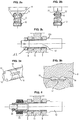
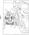
- the test device illustrated on the Figures 5 to 7 comprises a lever arm 30 pivotally mounted on a support 31. At its end opposite its gripping portion, the lever arm piece 30 terminates in a stop 32 intended to cooperate with a complementary U-shape 36 belonging to a tool 33, said stop 32 bearing on the inner flanks of the U-shaped in which it is received when the lever arm is tilted in one direction or the other.
- the support 31 may be an attached vice, for example screwed, on a mechanically decoupled structure with respect to the secondary path, in this case on the gimbal system 4 of the primary path.
- Other embodiments would of course be conceivable.
- the support 31 could in particular be based on a part of the primary track or on the structure of the aircraft itself.
- the tool 33 encloses at least one element of the high fastener of the secondary track in a manner that makes it possible to exert on said high fastener, by tilting of the lever arm 30 and transmission of a force by putting in support of the abutment 32 on the inner flanks of the U-shape 36, either a tensile force, a compression force, or even, as in the a case which is here exemplified, a tensile force or a compressive force in the direction of tilting of the lever arm 30.
- This clipping tool 33 is in this case made by assembling two front and rear plates 34, by means of two clasping screws 35a and 35b, which are positioned in a reduced space between a clevis edge of the part 8 and a rim that presents, at the right of this edge, the piece which constitutes the female form 10.
- clamping tool 33 can only bear on the upper part of the part 8 and only allow to exercise a compressive force.
- the tool 33 is able to bear on at least one zone of at least one element of the secondary path.
- the tool 33 comprising in particular the front and rear plates 34 linked by the tightening screws 35a, 35b, is able to clamp around an area of an element of the upper fastener of the secondary track, as illustrated for example in figure 7 .
- the figures 8 and 9 illustrate an effort setting of the secondary path by the test device.
- the figure 9 illustrates an effort in the opposite direction.
- a first possibility is to position an operator in the cockpit of the aircraft, the role of which is to verify that an alarm, which is triggered when the detection means have detected a charging of the secondary channel, has occurred. well triggered.
- Another possibility is to use a detector, which is connected to a computer of the aircraft in communication with the detection means 20.
- test device is dismounted from the aircraft by unscrewing the tightening screws 35a, 35b and dismounting the clamping vice 31.
Description
La présente invention est relative à un dispositif de test de la détection d'effort sur un actionneur de commande de vol. Elle concerne également un procédé de test.The present invention relates to a device for testing the detection of force on a flight control actuator. It also relates to a test method.
Notamment, mais non limitativement, elle concerne le test de la détection de la reprise d'effort par une voie secondaire d'un actionneur de commande de vol d'aéronef et trouve notamment avantageusement application dans le cas d'actionneur de type THSA (Trimmable Horizontal Stabilizer Actuator).In particular, but not exclusively, it relates to the test of the detection of the return of force by a secondary path of an aircraft flight control actuator and finds particularly advantageous application in the case of actuator type THSA (Trimmable Horizontal Stabilizer Actuator).
On sait que classiquement, de tels actionneurs comportent deux voies mécaniques, l'une primaire, l'autre secondaire, cette dernière étant destinée à reprendre l'effort lorsque la voie primaire est défaillante.It is known that, conventionally, such actuators comprise two mechanical ways, one primary, the other secondary, the latter being intended to resume the effort when the primary track is failing.
En fonctionnement sur la voie primaire, les efforts transitent par une vis à billes ou à rouleaux creuse. Cette caractéristique permet d'y loger une tige de sécurité (barre dite « fail safe »), rainurée à ses extrémités et reliée avec jeu à la vis. Cette structure assure la continuité de la transmission des efforts et de la rotation de l'ensemble (en évitant une séparation axiale des éléments de la vis, en cas de rupture de la vis elle-même). La vis se termine à une de ses extrémités par une pièce d'attache par laquelle elle est reliée à l'aéronef (attache haute primaire). En cas de défaillance de celle-ci, les efforts sont repris par la tige de sécurité dont l'extrémité est une forme mâle (par exemple une sphère) disposée dans une forme femelle d'une pièce d'attache de la voie secondaire (attache haute secondaire). Cette attache haute secondaire est elle-même reliée à l'aéronef au moyen d'une pièce d'attache avion différente de celle utilisée pour supporter la voie primaire.In operation on the primary track, the forces pass through a ball screw or hollow roller. This feature allows to house a safety rod (bar called "fail safe"), grooved at its ends and connected with play with the screw. This structure ensures the continuity of the transmission of forces and the rotation of the assembly (avoiding an axial separation of the elements of the screw, in case of rupture of the screw itself). The screw ends at one of its ends by a fastener by which it is connected to the aircraft (primary high fastener). In case of failure thereof, the forces are taken up by the safety rod whose end is a male shape (for example a sphere) arranged in a female form of a fastener part of the secondary track (attachment high school). This secondary high attachment is itself connected to the aircraft by means of an aircraft attachment part different from that used to support the primary route.
En fonctionnement normal, lorsque la voie primaire porte l'effort, il existe un jeu entre la forme mâle qui termine la tige de sécurité et la forme femelle de la pièce d'attache de la voie secondaire, de sorte que la pièce d'attache secondaire avion ne supporte pas d'autre effort que le poids de la pièce d'attache femelle secondaire du THSA.In normal operation, when the primary track carries the force, there is a clearance between the male form which terminates the safety rod and the female form of the fastener part of the secondary track, so that the attachment piece Secondary aircraft does not support any other effort than the weight of the secondary female tether of the THSA.
Lors de la défaillance de la voie primaire, la forme mâle qui termine la vis vient en contact avec la forme femelle de la pièce d'attache de la voie secondaire ce qui entraine la reprise d'effort par la chape de fixation secondaire avion.When the primary track fails, the male form that terminates the screw comes into contact with the female form of the track attachment piece secondary which causes the recovery of effort by the secondary fixing yoke plane.
Il existe divers dispositifs de détection d'effort intégrés à l'actionneur de commande de vol permettant de détecter la reprise d'effort de la voie secondaire. Un exemple de solution en ce sens a par exemple été décrit par la demanderesse dans sa demande
Néanmoins, il n'existe pas à ce jour de solution simple permettant de tester au sol le fonctionnement de tels dispositifs de détection de la reprise d'effort par une voie secondaire d'un actionneur de commande de vol.Nevertheless, there is currently no simple solution for ground testing the operation of such devices for detecting the recovery of force by a secondary path of a flight control actuator.
C'est pourquoi, on souhaite pouvoir proposer des solutions permettant de tester de tels dispositifs, notamment lors de la vérification périodique de l'avion au sol.This is why we want to be able to propose solutions that make it possible to test such devices, in particular during the periodic verification of the aircraft on the ground.
On souhaite également disposer de solutions de test pouvant être aisément mises en place sur un avion au sol.It is also desired to have test solutions that can be easily installed on a ground plane.
L'invention propose un dispositif selon la revendication 1 pour le test de moyens de détection de la mise sous charge de la voie secondaire d'un actionneur de commande de vol du type comportant une voie primaire et une voie secondaire apte à reprendre l'effort de la voie primaire en cas de défaillance de celle-ci, caractérisé en ce qu'il comprend un outil apte à prendre appui sur au moins une zone d'au moins un élément de la voie secondaire, ainsi qu'un bras de levier qui par basculement permet la mise en appui de l'outil sur ladite zone afin qu'il exerce un effort de traction et/ou compression sur la voie secondaire, ledit bras de levier étant monté pivotant sur un support apte à être fixé sur une structure mécaniquement indépendante de la voie secondaire.The invention proposes a device according to
L'invention comprend également un procédé de test selon la revendication 6.The invention also comprises a test method according to claim 6.
Un avantage de l'invention est de proposer une solution simple permettant de tester au sol le fonctionnement d'un dispositif de détection de la reprise d'effort par une voie secondaire d'un actionneur de commande de vol, pour des raisons de maintenance de l'avion notamment.An advantage of the invention is to propose a simple solution for ground testing the operation of a detection device of the recovery of effort by a secondary path of a flight control actuator, for reasons of maintenance of the aircraft in particular.
Un autre avantage de l'invention est de proposer une solution qui s'adapte directement sur l'avion, afin de faciliter les opérations de vérification et de maintenance.Another advantage of the invention is to propose a solution that adapts directly to the aircraft, in order to facilitate the verification and maintenance operations.
Un autre avantage encore de l'invention est de proposer une solution de test qui s'adapte directement sur l'avion de manière simple et peu invasive.Yet another advantage of the invention is to propose a test solution that adapts directly to the aircraft in a simple and minimally invasive manner.
Un autre avantage encore de l'invention est de pouvoir proposer une solution de test qui entraîne le moins de dysfonctionnements possibles dans le cas où la procédure de test est conduite avec des erreurs et/ou des oublis, et ce afin de garantir une sécurité maximale.Another advantage of the invention is to be able to propose a test solution that causes the least possible malfunctions in the case where the test procedure is conducted with errors and / or omissions, and this to ensure maximum security .
D'autres caractéristiques et avantages de l'invention ressortiront encore de la description qui suit, laquelle est purement illustrative et non limitative, et doit être lue en regard des dessins annexés sur lesquels :
- la
figure 1 est une représentation schématique illustrant le principe d'un actionneur de commande de vol; - les
figures 2a à 2c sont des représentations schématiques en vue de côté et en coupe illustrant la fixation de l'attache haute de la voie secondaire; - les
figures 3a et 3b illustrent un exemple de réalisation de moyens de détection ; - la
figure 4 est une représentation en coupe d'une vis permettant la fixation de l'attache haute de la voie secondaire ; - les
figures 5 et6 sont des représentations en perspective du dispositif de test de détection de la reprise d'effort par une voie secondaire d'un actionneur de commande de vol, mis en place sur un aéronef ; - la
figure 7 est une vue latérale du dispositif desfigures 5 et6 ; - les
figures 8 et9 sont des représentations du dispositif desfigures 5 ,6 et7 respectivement lors d'une reprise d'effort en compression et lors d'une reprise d'effort en traction.
- the
figure 1 is a schematic representation illustrating the principle of a flight control actuator; - the
Figures 2a to 2c are diagrammatic representations in side and sectional view illustrating the fixing of the upper fastener of the secondary track; - the
Figures 3a and 3b illustrate an exemplary embodiment of detection means; - the
figure 4 is a sectional representation of a screw for fixing the upper fastener of the secondary track; - the
figures 5 and6 are perspective representations of the test device for detecting the recovery of force by a secondary path of a flight control actuator, installed on an aircraft; - the
figure 7 is a side view of the devicefigures 5 and6 ; - the
figures 8 and9 are representations of the device of thefigures 5 ,6 and7 respectively during a compression force recovery and during a tensile force recovery.
On a représenté schématiquement sur la
Cet actionneur 1 est par exemple un vérin de type THSA, pour la commande d'un plan 2 horizontal variable d'aéronef.Diagrammatically shown on the
This
Il comporte une voie primaire qui comprend une vis creuse 3 reliée à une extrémité, par un système à cardan 4, à la structure S1 de l'avion. La voie primaire comprend également un écrou 5, qui coopère avec la vis 3 en étant monté sur celle-ci et qui est relié au plan 2 à commander, par exemple par un autre système 6 à cardan.It comprises a primary track which comprises a
Une tige 9 de sécurité s'étend à l'intérieur de la vis 3 creuse. Cette tige 9 se termine par une tête 7 sphérique placée avec jeu à l'intérieur d'une forme sphérique femelle 10 d'une pièce 8 d'attache de la voie secondaire, cette pièce 8 d'attache étant elle-même fixée à une structure S2 de l'avion.A safety rod 9 extends inside the
Cet actionneur est par exemple commandé par un moteur hydraulique ou électrique M, qui entraîne la vis 3 en rotation et déplace l'écrou 5 en translation, ce dernier étant à cet effet bloqué en rotation. Le déplacement en translation de l'écrou 5 permet ainsi de commander le basculement que l'on souhaite donner au plan horizontal variable 2.This actuator is for example controlled by a hydraulic or electric motor M, which drives the
On a représenté sur les
Comme one peut le voir sur ces figures, la pièce 8 est un étrier qui comporte deux chapes entre lesquelles est reçue la chape 11. Deux vis 12 de fixation parallèles s'étendent à travers les chapes de la pièce 8 et la pièce 11, l'ensemble étant fixé par serrage entre des têtes 12a qui terminent les vis 12 de fixation à une extrémité et des écrous 13 dont le filetage coopère avec celui des vis 12 de fixation à leurs autres extrémités.
Dans ce mode de réalisation, la forme femelle 10 est réalisée par une pièce distincte de la pièce d'attache 8, cette pièce d'attache 8 étant rapportée sur la pièce qui constitue ladite forme femelle 10.As can be seen in these figures, the
In this embodiment, the
On désigne par attache haute de la voie secondaire l'ensemble constitué par les pièces 8, 10, 11 et 12.The upper part of the secondary channel designates the assembly constituted by the
Des moyens 20 de détection d'effort sont disposés de telle façon à pouvoir détecter la mise sous charge de l'attache haute de la voie secondaire.Force detection means 20 are arranged in such a way as to be able to detect the loading of the high fastener of the secondary channel.
Des moyens de détections aptes à détecter un effort sont disposés sur au moins l'une des vis 12, ou sur au moins l'une des deux chapes de la pièce 8, ou encore sur des bagues interposées entre la vis 12 et les chapes et/ou l'écrou 13. De façon plus générale, ces moyens de détection peuvent être disposés sur toute pièce participant à l'attache haute de la voie secondaire.Detection means capable of detecting a force are arranged on at least one of the
Plusieurs solutions de moyens de détection de ce type ont notamment été proposées par la demanderesse, comme par exemple dans sa demande
Ces solutions sont par exemple à jauge de contrainte et poinçons, ou encore à lames piézoélectriques destinées à exciter la vis 12 autour de sa ou ses fréquence(s) de résonnance, ou encore à bague à capteur de pression, par exemple du type à pont de silicium.These solutions are, for example, strain gages and punches, or else piezoelectric blades intended to excite the
Les
Des poinçons 16 en saillie sur la chape viennent en appui sur les lames à jauge de contrainte et les déforment lorsque les pièces de la voie secondaire sont en charge, soit en traction, soit en compression.
Ces moyens de détection d'effort 20 sont par exemple reliés au calculateur de l'aéronef, qui traite les mesures réalisées par lesdits moyens pour en déduire une mise sous charge de la voie secondaire et déclencher le cas échéant les alarmes correspondantes.These effort detection means 20 are for example connected to the computer of the aircraft, which processes the measurements made by said means to deduce a charging of the secondary path and trigger if necessary the corresponding alarms.
La
Le dispositif de test illustré sur les
Le support 31 peut être un étau rapporté, par exemple vissé, sur une structure découplée mécaniquement par rapport à la voie secondaire, en l'occurrence sur le système à cardan 4 de la voie primaire. D'autres modes de réalisation seraient bien entendu envisageables. Le support 31 pourrait notamment prendre appui sur une pièce de la voie primaire ou sur la structure de l'avion elle-même.The
L'outil 33 enserre au moins un élément de l'attache haute de la voie secondaire d'une façon qui permet d'exercer sur ladite attache haute, par basculement du bras de levier 30 et transmission d'un effort par mise en appui de la butée 32 sur les flancs intérieurs de la forme en U 36, soit un effort de traction, soit un effort de compression, soit même, comme dans le cas qui est ici exemplifié, un effort de traction ou un effort de compression selon le sens de basculement du bras de levier 30.The
Cet outil 33 d'enserrement est en l'occurrence réalisé par assemblage de deux plaques avant et arrière 34, au moyen de deux vis d'enserrement 35a et 35b, qui se positionnent dans un espace réduit entre une arête de chape de la pièce 8 et un rebord que présente, au droit de cette arête, la pièce qui constitue la forme femelle 10.This
De cette façon, on dispose d'un outil 33 qui enserre la pièce 8 et est apte à venir en appui soit sur l'arête de la pièce 8 soit sur le rebord de la pièce 10, de sorte qu'un mouvement de basculement du bras de levier 30 génère, selon le sens de ce mouvement de basculement, une traction ou une compression sur la voie secondaire.In this way, there is a
D'autres configurations pourraient être envisagées. Par exemple, l'outil 33 d'enserrement peut ne prendre appui que sur la partie haute de la pièce 8 et ne permettre que d'exercer un effort en compression.Other configurations could be considered. For example, the
L'outil 33 est apte à prendre appui sur au moins une zone d'au moins un élément de la voie secondaire.The
Avantageusement, l'outil 33, comprenant notamment les plaques avant et arrière 34 liées par les vis d'enserrement 35a,35b, est apte à faire pince autour d'une zone d'un élément de l'attache haute de la voie secondaire, comme illustré par exemple en
Les
Le cas échéant, dans les structures utilisant un boitier 23 ressort, on dessert préalablement celui-ci pour éviter des frictions mécaniques et permettre la remise à zéro des moyens de détection de la mise sous charge de la voie secondaire.If necessary, in the structures using a
Dans le cas de la
Le pivotement vers le bas du bras de levier 30 autour de son axe de pivotement, bascule la butée 32 en appui contre le flanc intérieur haut de la forme en U 36. L'effort d'appui est transmis à la pièce 8 d'attache, appartenant à l'attache haute de la voie secondaire, par l'intermédiaire de l'outil 33 d'enserrement.The downward pivoting of the
La
Lors d'une mise en charge au moyen du dispositif de test qui vient d'être décrit, on vérifie que les moyens 20 de détection de la mise sous charge de la voie secondaire ont bien détecté l'effort appliqué. Cette vérification peut être faite de plusieurs manières, en utilisant ou non des moyens électroniques spécifiquement dédiés.During loading by means of the test device which has just been described, it is verified that the means 20 for detecting the loading of the secondary channel have detected the applied force. This verification can be done in several ways, using or not dedicated electronic means.
Une première possibilité est de positionner un opérateur dans le cockpit de l'aéronef, dont le rôle est de vérifier qu'une alarme, qui se déclenche lorsque les moyens 20 de détection ont détecté une mise sous charge de la voie secondaire, s'est bien déclenchée.A first possibility is to position an operator in the cockpit of the aircraft, the role of which is to verify that an alarm, which is triggered when the detection means have detected a charging of the secondary channel, has occurred. well triggered.
Une autre possibilité encore est d'utiliser un détecteur, que l'on vient connecter à un calculateur de l'avion en communication avec les moyens 20 de détection.Another possibility is to use a detector, which is connected to a computer of the aircraft in communication with the detection means 20.
Une fois les tests en traction et/ou compression terminés, le dispositif de test est démonté de l'aéronef en dévissant les vis d'enserrement 35a, 35b et en démontant l'étau de serrage 31.Once the tensile and / or compression tests have been completed, the test device is dismounted from the aircraft by unscrewing the tightening
A l'issue du test, les boitiers ressort 23 et les écrous 13 sont remis en place.At the end of the test, the
Claims (8)
- Device for testing of means for detection of the loading of the secondary channel of a flight control actuator of the type comprising a primary channel and a secondary channel capable of bearing the load of the primary channel in case of a failure thereof, characterized in that it includes a tool (33) capable of being supported on at least one area of at least one element of the secondary channel, as well as a lever arm (30) which, by tilting, is capable of enabling the tool to be supported on said area, so that it exerts a tensile and/or compressive force on the secondary channel, said lever arm (30) being mounted so that it pivots on a support (31) capable of being attached to a structure that is mechanically independent of the secondary channel.
- Device according to Claim 1, characterized in that the tool (33) is capable of enclosing at least one area of at least one element of the upper attachment of the secondary channel.
- Device according to Claim 2, in which the tool (33) includes an assembly including two plates (34) connected by two clamping screws (35a, 35b), capable of forming a clamp around an area of an upper attachment of the secondary channel.
- Device according to any one of Claims 1 to 3, characterized in that the tool (33) has a U shape (36) in which an abutment (32) is received, which terminates the arm forming the lever (30) at its end opposite its gripping end, said abutment (32) resting against one and/or the other of the two internal flanks of the U shape (36) during the tilting of the lever arm (30) in one direction or another, and thus enabling the application of a force in one direction or the other on the secondary channel.
- Device according to any one of the preceding claims, in which the support (31) includes a vise capable of being connected to a part of the primary channel or of the structure of an aircraft.
- Method for testing of means for detection of the loading of the secondary channel of a flight control actuator of the type comprising a primary channel and a secondary channel capable of bearing the load of the primary channel in case of failure thereof, characterized in that a tensile and/or compressive force is exerted on the secondary channel by means of a tool (33) capable of being supported on at least one area of at least one element of the secondary channel, as well as by means of a lever arm (30) which, by tilting, enables the tool (33) to be supported, so that it exerts said tensile and/or compressive force on the secondary channel, said lever arm (30) being mounted so that it pivots on a support (31) capable of being attached to a structure that is mechanically independent of the secondary channel.
- Method according to Claim 6, in which, said tool (33) being capable of enclosing at least one area of at least one element of the upper attachment of the secondary channel, the support (31) of the lever arm (30) is attached to a structure that is mechanically independent of the secondary channel, and the enclosing tool (33) is attached around an area of an element of the upper attachment of the secondary channel, so as to form a clamp around said area.
- Method according to either Claim 6 or Claim 7, including a preliminary step of loosening a spring casing (23) and a nut (13), so as to avoid mechanical friction in order to enable the resetting to zero of the means (20) for detection of the loading of the secondary channel, and a step of retightening the spring casing (23) and the nut (13) at the end of the test.
Applications Claiming Priority (1)
| Application Number | Priority Date | Filing Date | Title |
|---|---|---|---|
| FR0958738A FR2953494B1 (en) | 2009-12-08 | 2009-12-08 | DEVICE FOR TESTING THE DETECTION OF THE EFFORT RESUME BY A SECONDARY PATH OF A FLIGHT CONTROL ACTUATOR, AND ASSOCIATED TEST METHOD |
Publications (2)
| Publication Number | Publication Date |
|---|---|
| EP2332838A1 EP2332838A1 (en) | 2011-06-15 |
| EP2332838B1 true EP2332838B1 (en) | 2016-07-13 |
Family
ID=42308330
Family Applications (1)
| Application Number | Title | Priority Date | Filing Date |
|---|---|---|---|
| EP10194205.0A Active EP2332838B1 (en) | 2009-12-08 | 2010-12-08 | Device for testing load bearing detection of a secondary channel of a flight control actuator, and associated testing method |
Country Status (4)
| Country | Link |
|---|---|
| US (1) | US8702034B2 (en) |
| EP (1) | EP2332838B1 (en) |
| CA (1) | CA2724857C (en) |
| FR (1) | FR2953494B1 (en) |
Families Citing this family (13)
| Publication number | Priority date | Publication date | Assignee | Title |
|---|---|---|---|---|
| FR2953494B1 (en) * | 2009-12-08 | 2012-02-17 | Goodrich Actuation Systems Sas | DEVICE FOR TESTING THE DETECTION OF THE EFFORT RESUME BY A SECONDARY PATH OF A FLIGHT CONTROL ACTUATOR, AND ASSOCIATED TEST METHOD |
| FR2959837B1 (en) * | 2010-05-07 | 2012-05-04 | Eurocopter France | SIMPLIFIED FLIGHT CONTROL SYSTEM HAVING A DEBRASABLE FRICTION DEVICE |
| FR3016607B1 (en) * | 2014-01-20 | 2016-01-22 | Sagem Defense Securite | ACTUATOR FOR CONTROLLING A HORIZONTAL STABILIZATION PLAN OF AN AIRCRAFT |
| CA2960572C (en) * | 2014-12-01 | 2021-05-04 | Goodrich Actuation Systems Sas | Horizontal stabiliser actuator with freeplay detecting features and method thereof |
| EP3072808B1 (en) | 2015-03-26 | 2017-10-25 | Goodrich Actuation Systems SAS | Upper attachment for trimmable horizontal stabiliser actuator |
| EP3072809B1 (en) | 2015-03-27 | 2020-07-15 | Goodrich Actuation Systems SAS | Lower attachment for trimmable horizontal stabiliser actuator |
| EP3081481B1 (en) | 2015-04-15 | 2021-09-22 | Goodrich Actuation Systems SAS | Check device for a flight actuator primary load path failure detection device |
| CA2919342C (en) | 2015-04-15 | 2023-08-15 | Goodrich Actuation Systems Sas | Check device for flight actuator primary load path failure detection device |
| US10444128B2 (en) * | 2016-10-10 | 2019-10-15 | The Boeing Company | Load path status detection system |
| US10974846B2 (en) * | 2016-12-09 | 2021-04-13 | Parker-Hannifin Corporation | Fixed end electronic detection of secondary load path engagement of aircraft flight control actuator |
| EP3404395B1 (en) | 2017-05-19 | 2020-01-29 | Goodrich Actuation Systems SAS | Test method and apparatus for flight actuator check device |
| EP3403925B1 (en) * | 2017-05-19 | 2021-03-31 | Goodrich Actuation Systems SAS | Lower attachment system for a trimmable horizontal stabiliser actuator |
| CN108170152B (en) * | 2017-12-04 | 2020-12-29 | 中国飞机强度研究所 | Active control method for aircraft course restraining point error |
Family Cites Families (17)
| Publication number | Priority date | Publication date | Assignee | Title |
|---|---|---|---|---|
| GB749253A (en) * | 1953-01-30 | 1956-05-23 | Northrop Aircraft Inc | Improvements in or relating to control system for an airplane |
| US5628477A (en) * | 1995-02-13 | 1997-05-13 | The Boeing Company | Auxiliary airfoil lost motion detector and actuator |
| US6389915B1 (en) * | 1999-05-17 | 2002-05-21 | Alliedsignal, Inc. | Dual load path ball screw with rod end swivel |
| FR2811780B1 (en) * | 2000-07-13 | 2002-08-30 | Aerospatiale Matra Airbus | METHOD AND DEVICE FOR CONTROLLING MANEUVERING DEVICES OF AN AIRCRAFT WITH ELECTRIC BACKUP MODULES |
| US6578425B2 (en) * | 2001-05-29 | 2003-06-17 | Honeywell Inc. | Apparatus and method for verifying the dynamic stiffness capability of hydraulic servo actuators |
| US6659399B1 (en) * | 2002-11-25 | 2003-12-09 | The Boeing Company | Compact linear split sleeves for accurate rigging in confined space |
| US6672540B1 (en) * | 2002-12-03 | 2004-01-06 | Rockwell Collins, Inc. | Actuator for aircraft stabilizers with a failure responsive lock control mechanism |
| ITRM20030169A1 (en) * | 2003-04-11 | 2004-10-12 | Umbra Cuscinetti Spa | BALL RECIRCULATION ACTUATOR FOR AIRCRAFT GOVERNMENT SURFACES. |
| US7607611B2 (en) * | 2005-05-11 | 2009-10-27 | Honeywell International Inc. | Flight control surface actuation system with redundantly configured and lockable actuator assemblies |
| FR2891051B1 (en) * | 2005-09-22 | 2007-10-19 | Airbus France Sas | METHOD AND DEVICE FOR REALIZING AT LEAST ONE FLIGHT TEST ON AN AIRCRAFT AND APPLICATIONS |
| US7690597B2 (en) * | 2006-07-17 | 2010-04-06 | Eaton Corporation | Flap actuator |
| US7641145B2 (en) * | 2006-11-21 | 2010-01-05 | Eaton Corporation | Apparatus for moving a control surface |
| FR2912374B1 (en) * | 2007-02-08 | 2009-05-08 | Goodrich Actuation Systems Sas | DETECTION OF THE RETURN OF EFFORT BY A SECONDARY CHANNEL OF A FLIGHT CONTROL ACTUATOR |
| FR2913949B1 (en) * | 2007-03-23 | 2009-10-02 | Goodrich Actuation Systems Sas | IMPROVEMENTS IN THE DETECTION OF THE RETRIEVAL OF EFFORT OF THE SECONDARY PATH OF A FLIGHT CONTROL ACTUATOR. |
| FR2916023B1 (en) * | 2007-05-11 | 2009-08-21 | Goodrich Actuation Systems Sas | FUSIBLE MECHANICAL CONNECTION BETWEEN TWO NUTS ON A FAILURE SAFETY SCREW ASSEMBLY. |
| US7686680B2 (en) * | 2007-06-26 | 2010-03-30 | Honeywell International Inc. | Closed-loop cabin pressure control system test method with actual pressure feedback |
| FR2953494B1 (en) * | 2009-12-08 | 2012-02-17 | Goodrich Actuation Systems Sas | DEVICE FOR TESTING THE DETECTION OF THE EFFORT RESUME BY A SECONDARY PATH OF A FLIGHT CONTROL ACTUATOR, AND ASSOCIATED TEST METHOD |
-
2009
- 2009-12-08 FR FR0958738A patent/FR2953494B1/en active Active
-
2010
- 2010-12-08 EP EP10194205.0A patent/EP2332838B1/en active Active
- 2010-12-08 US US12/962,883 patent/US8702034B2/en active Active
- 2010-12-08 CA CA2724857A patent/CA2724857C/en active Active
Also Published As
| Publication number | Publication date |
|---|---|
| CA2724857A1 (en) | 2011-06-08 |
| CA2724857C (en) | 2018-03-06 |
| FR2953494B1 (en) | 2012-02-17 |
| FR2953494A1 (en) | 2011-06-10 |
| EP2332838A1 (en) | 2011-06-15 |
| US8702034B2 (en) | 2014-04-22 |
| US20110132106A1 (en) | 2011-06-09 |
Similar Documents
| Publication | Publication Date | Title |
|---|---|---|
| EP2332838B1 (en) | Device for testing load bearing detection of a secondary channel of a flight control actuator, and associated testing method | |
| EP2000405B1 (en) | Improved load detection on a flight control actuator | |
| EP2563655B1 (en) | Device for detecting breakage of a primary path in a flight control actuator | |
| EP2164685B1 (en) | Clamp for manipulating robot with enhanced gripping accuracy and manipulating robot comprising at least one such clamp | |
| WO2015107208A2 (en) | Actuator for controlling a horizontal stabiliser of an aircraft | |
| CA2753950C (en) | Skid-type landing gear and aircraft equipped with such a landing gear | |
| FR3093704A1 (en) | Rear engine attachment of an aircraft propulsion unit | |
| FR3058986A1 (en) | REAR ATTACHMENT OF AN AIRCRAFT ENGINE COMPRISING BREAKWATER LIGHTS | |
| EP3398819A1 (en) | Device for attaching a security module to a vehicle steering wheel | |
| EP2439140B1 (en) | Spigot fastener comprising means for measuring the loads generated by an aircraft engine. | |
| WO2020136356A1 (en) | Force application device for a control stick of an aircraft | |
| EP2753543A1 (en) | Device for coupling an actuator for controlling the landing gear of an aircraft | |
| EP2384970B1 (en) | Flight control system, flight control device comprising said system, and use of said system | |
| FR3036375A1 (en) | LANDING TRAIN FOR AN AIRCRAFT AND HAVING A LATCHING SYSTEM IN STORAGE POSITION | |
| FR2950429A1 (en) | DEVICE FOR MEASURING A TORSOR OF THE EFFORTS AND MOMENTS GENERATED BY A PROPELLANT AIRCRAFT ASSEMBLY | |
| EP3636474A1 (en) | Locking device, in particular device for storing a breathing mask intended for supplying oxygen in an aircraft and oxygen supply system | |
| FR3082826A1 (en) | FIXING INTERFACE, FLOAT SYSTEM AND VEHICLE | |
| FR2893910A1 (en) | Aircraft structure`s flight control surface defect detecting device, has safety bar whose rounded end is moved in rotation towards secondary attachment to contact coupling bar head with secondary attachment | |
| FR3127480A1 (en) | Obstruction to secure an aircraft on a landing grid and aircraft | |
| FR3066561A1 (en) | FUSE-FORMING FERRULE FOR A TRAINING SYSTEM IN TRANSLATION OF A VERIN | |
| FR3074204A1 (en) | DETECTION DEVICE AND METHOD FOR DEPLOYING AND RETRACTING SAID DEVICE | |
| EP3019430A1 (en) | Lifting bolt | |
| FR3029162A1 (en) | ARRANGEMENT FOR A MOTOR VEHICLE WITH AN ADJUSTABLE SPACER ARRANGED BETWEEN TWO STRUCTURAL ELEMENTS | |
| FR3095480A3 (en) | Connection between two assembled elements articulated to each other. | |
| EP2192373B1 (en) | Device allowing automatic uncoupling of the two parts of a connector |
Legal Events
| Date | Code | Title | Description |
|---|---|---|---|
| PUAI | Public reference made under article 153(3) epc to a published international application that has entered the european phase |
Free format text: ORIGINAL CODE: 0009012 |
|
| 17P | Request for examination filed |
Effective date: 20101208 |
|
| AK | Designated contracting states |
Kind code of ref document: A1 Designated state(s): AL AT BE BG CH CY CZ DE DK EE ES FI FR GB GR HR HU IE IS IT LI LT LU LV MC MK MT NL NO PL PT RO RS SE SI SK SM TR |
|
| AX | Request for extension of the european patent |
Extension state: BA ME |
|
| RIC1 | Information provided on ipc code assigned before grant |
Ipc: F16H 25/20 20060101ALN20151120BHEP Ipc: B64C 13/36 20060101ALI20151120BHEP Ipc: B64C 13/28 20060101ALI20151120BHEP Ipc: B64C 13/42 20060101ALI20151120BHEP Ipc: B64F 5/00 20060101AFI20151120BHEP |
|
| GRAP | Despatch of communication of intention to grant a patent |
Free format text: ORIGINAL CODE: EPIDOSNIGR1 |
|
| INTG | Intention to grant announced |
Effective date: 20160118 |
|
| RIC1 | Information provided on ipc code assigned before grant |
Ipc: B64C 13/28 20060101ALI20160108BHEP Ipc: B64C 13/36 20060101ALI20160108BHEP Ipc: B64F 5/00 20060101AFI20160108BHEP Ipc: F16H 25/20 20060101ALN20160108BHEP Ipc: B64C 13/42 20060101ALI20160108BHEP |
|
| GRAS | Grant fee paid |
Free format text: ORIGINAL CODE: EPIDOSNIGR3 |
|
| GRAA | (expected) grant |
Free format text: ORIGINAL CODE: 0009210 |
|
| AK | Designated contracting states |
Kind code of ref document: B1 Designated state(s): AL AT BE BG CH CY CZ DE DK EE ES FI GB GR HR HU IE IS IT LI LT LU LV MC MK MT NL NO PL PT RO RS SE SI SK SM TR |
|
| RBV | Designated contracting states (corrected) |
Designated state(s): AL AT BE BG CH CY CZ DE DK EE ES FI GB GR HR HU IE IS IT LI LT LU LV MC MK MT NL NO PL PT RO RS SE SI SK SM TR |
|
| REG | Reference to a national code |
Ref country code: GB Ref legal event code: FG4D Free format text: NOT ENGLISH |
|
| REG | Reference to a national code |
Ref country code: AT Ref legal event code: REF Ref document number: 812063 Country of ref document: AT Kind code of ref document: T Effective date: 20160715 Ref country code: CH Ref legal event code: EP |
|
| REG | Reference to a national code |
Ref country code: IE Ref legal event code: FG4D Free format text: LANGUAGE OF EP DOCUMENT: FRENCH |
|
| REG | Reference to a national code |
Ref country code: DE Ref legal event code: R096 Ref document number: 602010034621 Country of ref document: DE |
|
| REG | Reference to a national code |
Ref country code: LT Ref legal event code: MG4D |
|
| REG | Reference to a national code |
Ref country code: NL Ref legal event code: MP Effective date: 20160713 |
|
| REG | Reference to a national code |
Ref country code: AT Ref legal event code: MK05 Ref document number: 812063 Country of ref document: AT Kind code of ref document: T Effective date: 20160713 |
|
| PG25 | Lapsed in a contracting state [announced via postgrant information from national office to epo] |
Ref country code: RS Free format text: LAPSE BECAUSE OF FAILURE TO SUBMIT A TRANSLATION OF THE DESCRIPTION OR TO PAY THE FEE WITHIN THE PRESCRIBED TIME-LIMIT Effective date: 20160713 Ref country code: LT Free format text: LAPSE BECAUSE OF FAILURE TO SUBMIT A TRANSLATION OF THE DESCRIPTION OR TO PAY THE FEE WITHIN THE PRESCRIBED TIME-LIMIT Effective date: 20160713 Ref country code: HR Free format text: LAPSE BECAUSE OF FAILURE TO SUBMIT A TRANSLATION OF THE DESCRIPTION OR TO PAY THE FEE WITHIN THE PRESCRIBED TIME-LIMIT Effective date: 20160713 Ref country code: IS Free format text: LAPSE BECAUSE OF FAILURE TO SUBMIT A TRANSLATION OF THE DESCRIPTION OR TO PAY THE FEE WITHIN THE PRESCRIBED TIME-LIMIT Effective date: 20161113 Ref country code: FI Free format text: LAPSE BECAUSE OF FAILURE TO SUBMIT A TRANSLATION OF THE DESCRIPTION OR TO PAY THE FEE WITHIN THE PRESCRIBED TIME-LIMIT Effective date: 20160713 Ref country code: NL Free format text: LAPSE BECAUSE OF FAILURE TO SUBMIT A TRANSLATION OF THE DESCRIPTION OR TO PAY THE FEE WITHIN THE PRESCRIBED TIME-LIMIT Effective date: 20160713 Ref country code: NO Free format text: LAPSE BECAUSE OF FAILURE TO SUBMIT A TRANSLATION OF THE DESCRIPTION OR TO PAY THE FEE WITHIN THE PRESCRIBED TIME-LIMIT Effective date: 20161013 |
|
| PG25 | Lapsed in a contracting state [announced via postgrant information from national office to epo] |
Ref country code: PT Free format text: LAPSE BECAUSE OF FAILURE TO SUBMIT A TRANSLATION OF THE DESCRIPTION OR TO PAY THE FEE WITHIN THE PRESCRIBED TIME-LIMIT Effective date: 20161114 Ref country code: LV Free format text: LAPSE BECAUSE OF FAILURE TO SUBMIT A TRANSLATION OF THE DESCRIPTION OR TO PAY THE FEE WITHIN THE PRESCRIBED TIME-LIMIT Effective date: 20160713 Ref country code: GR Free format text: LAPSE BECAUSE OF FAILURE TO SUBMIT A TRANSLATION OF THE DESCRIPTION OR TO PAY THE FEE WITHIN THE PRESCRIBED TIME-LIMIT Effective date: 20161014 Ref country code: ES Free format text: LAPSE BECAUSE OF FAILURE TO SUBMIT A TRANSLATION OF THE DESCRIPTION OR TO PAY THE FEE WITHIN THE PRESCRIBED TIME-LIMIT Effective date: 20160713 Ref country code: AT Free format text: LAPSE BECAUSE OF FAILURE TO SUBMIT A TRANSLATION OF THE DESCRIPTION OR TO PAY THE FEE WITHIN THE PRESCRIBED TIME-LIMIT Effective date: 20160713 Ref country code: SE Free format text: LAPSE BECAUSE OF FAILURE TO SUBMIT A TRANSLATION OF THE DESCRIPTION OR TO PAY THE FEE WITHIN THE PRESCRIBED TIME-LIMIT Effective date: 20160713 Ref country code: PL Free format text: LAPSE BECAUSE OF FAILURE TO SUBMIT A TRANSLATION OF THE DESCRIPTION OR TO PAY THE FEE WITHIN THE PRESCRIBED TIME-LIMIT Effective date: 20160713 |
|
| REG | Reference to a national code |
Ref country code: DE Ref legal event code: R097 Ref document number: 602010034621 Country of ref document: DE |
|
| PG25 | Lapsed in a contracting state [announced via postgrant information from national office to epo] |
Ref country code: EE Free format text: LAPSE BECAUSE OF FAILURE TO SUBMIT A TRANSLATION OF THE DESCRIPTION OR TO PAY THE FEE WITHIN THE PRESCRIBED TIME-LIMIT Effective date: 20160713 Ref country code: RO Free format text: LAPSE BECAUSE OF FAILURE TO SUBMIT A TRANSLATION OF THE DESCRIPTION OR TO PAY THE FEE WITHIN THE PRESCRIBED TIME-LIMIT Effective date: 20160713 |
|
| PLBE | No opposition filed within time limit |
Free format text: ORIGINAL CODE: 0009261 |
|
| STAA | Information on the status of an ep patent application or granted ep patent |
Free format text: STATUS: NO OPPOSITION FILED WITHIN TIME LIMIT |
|
| PG25 | Lapsed in a contracting state [announced via postgrant information from national office to epo] |
Ref country code: SM Free format text: LAPSE BECAUSE OF FAILURE TO SUBMIT A TRANSLATION OF THE DESCRIPTION OR TO PAY THE FEE WITHIN THE PRESCRIBED TIME-LIMIT Effective date: 20160713 Ref country code: BE Free format text: LAPSE BECAUSE OF NON-PAYMENT OF DUE FEES Effective date: 20161231 Ref country code: DK Free format text: LAPSE BECAUSE OF FAILURE TO SUBMIT A TRANSLATION OF THE DESCRIPTION OR TO PAY THE FEE WITHIN THE PRESCRIBED TIME-LIMIT Effective date: 20160713 Ref country code: BG Free format text: LAPSE BECAUSE OF FAILURE TO SUBMIT A TRANSLATION OF THE DESCRIPTION OR TO PAY THE FEE WITHIN THE PRESCRIBED TIME-LIMIT Effective date: 20161013 Ref country code: CZ Free format text: LAPSE BECAUSE OF FAILURE TO SUBMIT A TRANSLATION OF THE DESCRIPTION OR TO PAY THE FEE WITHIN THE PRESCRIBED TIME-LIMIT Effective date: 20160713 Ref country code: SK Free format text: LAPSE BECAUSE OF FAILURE TO SUBMIT A TRANSLATION OF THE DESCRIPTION OR TO PAY THE FEE WITHIN THE PRESCRIBED TIME-LIMIT Effective date: 20160713 |
|
| 26N | No opposition filed |
Effective date: 20170418 |
|
| REG | Reference to a national code |
Ref country code: CH Ref legal event code: PL |
|
| PG25 | Lapsed in a contracting state [announced via postgrant information from national office to epo] |
Ref country code: SI Free format text: LAPSE BECAUSE OF FAILURE TO SUBMIT A TRANSLATION OF THE DESCRIPTION OR TO PAY THE FEE WITHIN THE PRESCRIBED TIME-LIMIT Effective date: 20160713 |
|
| PG25 | Lapsed in a contracting state [announced via postgrant information from national office to epo] |
Ref country code: MC Free format text: LAPSE BECAUSE OF FAILURE TO SUBMIT A TRANSLATION OF THE DESCRIPTION OR TO PAY THE FEE WITHIN THE PRESCRIBED TIME-LIMIT Effective date: 20160713 |
|
| REG | Reference to a national code |
Ref country code: IE Ref legal event code: MM4A |
|
| PG25 | Lapsed in a contracting state [announced via postgrant information from national office to epo] |
Ref country code: CH Free format text: LAPSE BECAUSE OF NON-PAYMENT OF DUE FEES Effective date: 20161231 Ref country code: LU Free format text: LAPSE BECAUSE OF NON-PAYMENT OF DUE FEES Effective date: 20161208 Ref country code: LI Free format text: LAPSE BECAUSE OF NON-PAYMENT OF DUE FEES Effective date: 20161231 |
|
| PG25 | Lapsed in a contracting state [announced via postgrant information from national office to epo] |
Ref country code: IE Free format text: LAPSE BECAUSE OF NON-PAYMENT OF DUE FEES Effective date: 20161208 |
|
| REG | Reference to a national code |
Ref country code: BE Ref legal event code: MM Effective date: 20161231 |
|
| PG25 | Lapsed in a contracting state [announced via postgrant information from national office to epo] |
Ref country code: CY Free format text: LAPSE BECAUSE OF FAILURE TO SUBMIT A TRANSLATION OF THE DESCRIPTION OR TO PAY THE FEE WITHIN THE PRESCRIBED TIME-LIMIT Effective date: 20160713 Ref country code: HU Free format text: LAPSE BECAUSE OF FAILURE TO SUBMIT A TRANSLATION OF THE DESCRIPTION OR TO PAY THE FEE WITHIN THE PRESCRIBED TIME-LIMIT; INVALID AB INITIO Effective date: 20101208 |
|
| PG25 | Lapsed in a contracting state [announced via postgrant information from national office to epo] |
Ref country code: TR Free format text: LAPSE BECAUSE OF FAILURE TO SUBMIT A TRANSLATION OF THE DESCRIPTION OR TO PAY THE FEE WITHIN THE PRESCRIBED TIME-LIMIT Effective date: 20160713 Ref country code: MK Free format text: LAPSE BECAUSE OF FAILURE TO SUBMIT A TRANSLATION OF THE DESCRIPTION OR TO PAY THE FEE WITHIN THE PRESCRIBED TIME-LIMIT Effective date: 20160713 |
|
| PG25 | Lapsed in a contracting state [announced via postgrant information from national office to epo] |
Ref country code: MT Free format text: LAPSE BECAUSE OF FAILURE TO SUBMIT A TRANSLATION OF THE DESCRIPTION OR TO PAY THE FEE WITHIN THE PRESCRIBED TIME-LIMIT Effective date: 20160713 |
|
| PG25 | Lapsed in a contracting state [announced via postgrant information from national office to epo] |
Ref country code: AL Free format text: LAPSE BECAUSE OF FAILURE TO SUBMIT A TRANSLATION OF THE DESCRIPTION OR TO PAY THE FEE WITHIN THE PRESCRIBED TIME-LIMIT Effective date: 20160713 |
|
| REG | Reference to a national code |
Ref country code: DE Ref legal event code: R082 Ref document number: 602010034621 Country of ref document: DE |
|
| PGFP | Annual fee paid to national office [announced via postgrant information from national office to epo] |
Ref country code: IT Payment date: 20221122 Year of fee payment: 13 |
|
| PGFP | Annual fee paid to national office [announced via postgrant information from national office to epo] |
Ref country code: GB Payment date: 20231121 Year of fee payment: 14 |
|
| PGFP | Annual fee paid to national office [announced via postgrant information from national office to epo] |
Ref country code: DE Payment date: 20231121 Year of fee payment: 14 |