EP2332762A1 - Servo motor layout structure of saddle-ride type vehicle - Google Patents
Servo motor layout structure of saddle-ride type vehicle Download PDFInfo
- Publication number
- EP2332762A1 EP2332762A1 EP10177838A EP10177838A EP2332762A1 EP 2332762 A1 EP2332762 A1 EP 2332762A1 EP 10177838 A EP10177838 A EP 10177838A EP 10177838 A EP10177838 A EP 10177838A EP 2332762 A1 EP2332762 A1 EP 2332762A1
- Authority
- EP
- European Patent Office
- Prior art keywords
- servo motor
- saddle
- layout structure
- body frame
- ride type
- Prior art date
- Legal status (The legal status is an assumption and is not a legal conclusion. Google has not performed a legal analysis and makes no representation as to the accuracy of the status listed.)
- Granted
Links
Images




Classifications
-
- B—PERFORMING OPERATIONS; TRANSPORTING
- B62—LAND VEHICLES FOR TRAVELLING OTHERWISE THAN ON RAILS
- B62K—CYCLES; CYCLE FRAMES; CYCLE STEERING DEVICES; RIDER-OPERATED TERMINAL CONTROLS SPECIALLY ADAPTED FOR CYCLES; CYCLE AXLE SUSPENSIONS; CYCLE SIDECARS, FORECARS, OR THE LIKE
- B62K19/00—Cycle frames
- B62K19/30—Frame parts shaped to receive other cycle parts or accessories
-
- B—PERFORMING OPERATIONS; TRANSPORTING
- B62—LAND VEHICLES FOR TRAVELLING OTHERWISE THAN ON RAILS
- B62K—CYCLES; CYCLE FRAMES; CYCLE STEERING DEVICES; RIDER-OPERATED TERMINAL CONTROLS SPECIALLY ADAPTED FOR CYCLES; CYCLE AXLE SUSPENSIONS; CYCLE SIDECARS, FORECARS, OR THE LIKE
- B62K11/00—Motorcycles, engine-assisted cycles or motor scooters with one or two wheels
- B62K11/02—Frames
- B62K11/04—Frames characterised by the engine being between front and rear wheels
-
- B—PERFORMING OPERATIONS; TRANSPORTING
- B62—LAND VEHICLES FOR TRAVELLING OTHERWISE THAN ON RAILS
- B62K—CYCLES; CYCLE FRAMES; CYCLE STEERING DEVICES; RIDER-OPERATED TERMINAL CONTROLS SPECIALLY ADAPTED FOR CYCLES; CYCLE AXLE SUSPENSIONS; CYCLE SIDECARS, FORECARS, OR THE LIKE
- B62K25/00—Axle suspensions
- B62K25/04—Axle suspensions for mounting axles resiliently on cycle frame or fork
- B62K25/28—Axle suspensions for mounting axles resiliently on cycle frame or fork with pivoted chain-stay
- B62K25/283—Axle suspensions for mounting axles resiliently on cycle frame or fork with pivoted chain-stay for cycles without a pedal crank, e.g. motorcycles
Definitions
- This invention relates to the servo motor layout structure of a saddle-ride type vehicle.
- the servo motor is required to be arranged in another place, however, when the servo motor is arranged apart from the exhaust valve, a cable is often curved in laying out the cable depending upon the arrangement of a peripheral part and as it is thought that the torque of the servo motor is not enough, the layout requires a device.
- this invention is based upon the servo motor layout structure of a saddle-ride type vehicle provided with a servo motor for driving an exhaust valve and its object is to enable the servo motor to be efficiently arranged in a place except the downside of a seat, inhibiting the length and the curvature of a cable.
- the invention according to Claim 1 is based upon the servo motor layout structure of a saddle-ride type vehicle (for example, a motorcycle 1 in an embodiment) provided with an engine (for example, an engine 17 in the embodiment) supported by a body frame (for example, a body frame 5 in the embodiment), a swing arm (for example, a swing arm 14 in the embodiment) a front end of which is swingably supported by at least either of the body frame or the engine and a rear end of which journals a rear wheel (for example, a rear wheel 15 in the embodiment), an exhaust pipe (for example, an exhaust pipe 22 in the embodiment) connected to the engine, an exhaust valve (for example, an exhaust valve 51 in the embodiment) provided in the exhaust pipe, a servo motor (for example, a servo motor 56 in the embodiment) that drives the exhaust valve and a cable (for example, a cable 59 in the embodiment) that couples the exhaust valve and the servo motor, and has a characteristic that the exhaust valve and the servo motor
- the above-mentioned saddle-ride type vehicle includes the whole vehicles on each of which a rider rides with the rider straddling each vehicle body and also includes not only a motorcycle (including a motorbike and a scooter-type vehicle) but a three-wheeled vehicle (also including a vehicle provided with one wheel in the front and two wheels in the rear and a vehicle provided with two wheels in the front and one wheel in the rear) and a four-wheel vehicle.
- the invention according to Claim 2 has a characteristic that a servo motor stay (for example, a servo motor stay 60 in the embodiment) that assists the servo motor to be supported by the body frame is provided and the servo motor stay is provided with a beam part (for example, a beam part 62 in the embodiment) the front of which is fastened to a lower part of the body frame, a servo motor attachment (for example, a servo motor attachment 63 in the embodiment) provided to the rear of the beam part and a detent (for example, a detent 64 in the embodiment) extended forward from the servo motor attachment and coupled to the lower part of the body frame at the back of a part fastened to a vehicle body (for example, a part 61 fastened to a vehicle body in the embodiment) of the beam part.
- a servo motor stay for example, a servo motor stay 60 in the embodiment
- the servo motor stay is provided with a beam part (for example, a beam part 62 in the
- the invention according to Claim 3 has a characteristic that a main stand support (for example, a main stand support 46 in the embodiment) that journals a main stand (for example, a main stand 45 in the embodiment) is provided to the lower part of the body frame and the detent of the servo motor stay is fastened to a stand swinging shaft (for example, a pivot bolt 47 in the embodiment) in the main stand support via a pipe bush (for example, a pipe bush 67f in the embodiment).
- a main stand support for example, a main stand support 46 in the embodiment
- a main stand support 46 in the embodiment that journals a main stand (for example, a main stand 45 in the embodiment) is provided to the lower part of the body frame and the detent of the servo motor stay is fastened to a stand swinging shaft (for example, a pivot bolt 47 in the embodiment) in the main stand support via a pipe bush (for example, a pipe bush 67f in the embodiment).
- the invention according to Claim 4 has a characteristic that the main stand is provided with a pair of left and right legs (for example, legs 45a, 45b in the embodiment), the beam part of the servo motor stay is longitudinally extended passing between the left and right legs, its front is curved on one side in a direction of vehicle width in front of the main stand support and is fastened to a bottom of the body frame.
- the beam part of the servo motor stay is longitudinally extended passing between the left and right legs, its front is curved on one side in a direction of vehicle width in front of the main stand support and is fastened to a bottom of the body frame.
- the invention according to Claim 5 has a characteristic that the servo motor stay is provided with a plate member (for example, the servo motor attachment 63 in the embodiment) formed by bending a steel plate, the plate member is provided with a substantially horizontal lower horizontal plate (for example, a lower horizontal plate 65a in the embodiment), a vertical plate (for example, a rear vertical plate 65c, a vertical plate 66c in the embodiment) substantially vertically bent from one side edge of the lower horizontal plate, a pipe bush mounting part (for example, a round pipe joint 67d, a short pipe 67e in the embodiment) provided in front of the vertical plate and an upper horizontal plate (for example, a rear horizontal plate 65d and an upper horizontal plate 66f in the embodiment) substantially horizontally bent from an upper edge of the vertical plate, the vertical plate is extended forward to form the detent and the servo motor is mounted on the upper horizontal plate via rubber.
- a plate member for example, the servo motor attachment 63 in the embodiment formed by bending a steel plate
- the invention according to Claim 6 has a characteristic that a coupler locking hole (for example, a clip hole 56h in the embodiment) for locking a coupler check member (for example, a clip 56g in the embodiment) provided to a coupler (for example, a coupler 56f in the embodiment) of the servo motor is provided to the lower horizontal plate.
- a coupler locking hole for example, a clip hole 56h in the embodiment
- a coupler check member for example, a clip 56g in the embodiment
- a coupler for example, a coupler 56f in the embodiment
- the invention according to Claim 7 has a characteristic that a canister mounting part (for example, a canister supporting plate 68a in the embodiment) is further provided to the servo motor stay.
- a canister mounting part for example, a canister supporting plate 68a in the embodiment
- the invention according to Claim 8 has a characteristic that a rubber servo motor cover (for example, a servo motor cover 69 in the embodiment) is mounted on the servo motor.
- a rubber servo motor cover for example, a servo motor cover 69 in the embodiment
- the invention according to Claim 9 has a characteristic that a weight (for example, a weight 70 in the embodiment) is provided to the body frame with the weight covering a side of the servo motor.
- a weight for example, a weight 70 in the embodiment
- the invention according to Claim 10 has a characteristic that the servo motor is provided with the servo motor biased on one side based upon a center line of the vehicle body (for example, a center line CL of the vehicle body in the embodiment) in a bottom view of the vehicle body and the exhaust valve is provided with the exhaust valve biased on the other side based upon the center line of the vehicle body in the bottom view of the vehicle body.
- a center line of the vehicle body for example, a center line CL of the vehicle body in the embodiment
- the length and the curvature of the cable that couples the exhaust valve and the servo motor can be inhibited, arranging the exhaust valve and the servo motor in dead space under the swing arm.
- the servo motor when the servo motor is arranged under the swing arm, the servo motor is required to be supported by a cantilever if no supporting part is especially provided to the body frame, however, the servo motor can be stably and securely supported by the body frame by using the servo motor stay provided with the beam part and the detent positions attached to the body frame of which are longitudinally different.
- the detent can be coupled to the main stand support. Even if the servo motor stay is vertically vibrated due to irregularities of a road surface and others, vibration transmitted to the main stand support can be reduced because the detent is elastically supported via the pipe bush and a state in which the detent is supported can be more securely maintained.
- the servo motor stay can be attached to the body frame with the beam part avoiding the right and left legs.
- the servo motor stay can be provided at a low cost with simple configuration by bending the plate member and forming the detent and the part for mounting the servo motor via rubber.
- the detent is made of a plate, it is not bulky and the servo motor stay can be compacted.
- the coupler locking hole can be easily provided.
- the canister can be also supported by the servo motor stay in the dead space under the swing arm.
- an effect of disturbance such as a splash from a road surface on the servo motor arranged under the swing arm can be inhibited.
- the weight excellent in strength and rigidity can also function as a cover that covers the side of the servo motor.
- the servo motor is separated from the exhaust pipe and the heat of the exhaust pipe can be prevented from having an effect on the servo motor.
- a direction such as a longitudinal direction and a lateral direction in the following description shall be the same as a vehicular direction unless special description is made.
- an arrow FR in the drawing points to the front side of a vehicle
- LH points to the left of the vehicle
- UP points to the upside of the vehicle.
- a front wheel 2 of a motorcycle (a saddle-ride type vehicle) 1 is journaled to each lower end of a pair of right and left front forks 3 and an upper part of each front fork 3 is steerably journaled to a head pipe 6 at a front end of a body frame 5 via a steering stem 4.
- a handlebar 7 is attached onto a top bridge 4a of the steering stem 4.
- a rear wheel 15 of the motorcycle 1 is journaled to a rear end of a swing arm 14 and a front end of the swing arm 14 is vertically swingably journaled to a pivot frame 9 in a rear part of the body frame 5 and others.
- a rear cushion 16 is arranged between a front part of the swing arm 14 and the rear part of the body frame 5.
- the body frame 5 is formed by integrally bonding plural types of steel products (or castings) by welding and others and is a so-called monobackbone type acquired by extending one main frame 8 backward from the head pipe 6 to the pivot frame 9.
- the main frame 8 is extended backward, passing the upside of an engine (an internal combustion engine) 17 mounted inside the body frame 5, is curved downward, and is led and connected to an upper end of the vertically extended pivot frame 9 in an intermediate part in a longitudinal direction of a vehicle body.
- the main frame 8 and the pivot frame 9 are arranged in the center in a direction of vehicle width (a lateral direction) like the head pipe 6.
- a line CL in the drawing shows a lateral center line of the vehicle body.
- a pair of right and left pivot brackets 12 is attached on both right and left sides of the pivot frame 9 with the pivot frame laterally held between the pivot brackets.
- Each front end of a seat rail 13 and a support pipe 13a for the seat rail is attached on the rear upside of the main frame 8.
- the body frame 5 is acquired by separately configuring a front piece forming the circumference of the head pipe 6, a center piece forming the main frame 8 and a rear piece forming the circumference of the pivot frame 9 by aluminum casting for example and integrally welding the pieces.
- the right and left pivot brackets 12 configuring a part of the body frame 5 are also formed by aluminum casting like each piece and are integrally fastened and fixed to the pivot frame 9 by a bolt and others.
- a pivot part (not shown) which a pivot 12d of the swing arm 14 pierces is provided on the front side of a vertically intermediate part of the pivot frame 9, and left and right arm pivot parts 14d separately provided to each front end of left and right arms 14a, 14b of the swing arm 14 are respectively adjacently arranged outside the pivot part in the direction of vehicle width.
- Outer pivot parts 12c provided to the right and left pivot brackets 12 are respectively adjacently arranged outside the right and left arm pivot parts 14d in the direction of vehicle width.
- the front end of the swing arm 14 is vertically swingably journaled to the body frame 5 by piercing each pivot part with the pivot 12d laterally directed and coupling each pivot part.
- a reference sign 14c denotes a cross member that couples the fronts of the left and right arms 14a, 14b of the swing arm 14.
- the engine 17 is a parallel 4-cylinder engine having a rotational axis of a crank in the direction of vehicle width and has basic configuration in which a cylinder 19 is planted on a crankcase 18 diagonally forward and upward.
- Each of four throttle bodies 21 is connected to the rear of each cylinder 19 and each of four exhaust pipes 22 is similarly connected to the front of each cylinder 19.
- Each throttle body 21 is connected to an air cleaner case 25 arranged at the back of each throttle body.
- a reference sign 26 denotes an intake duct arranged along the left side of the air cleaner case 25 and open to the rear of the vehicle.
- each exhaust pipe 22 is suitably curved in front of the engine 17, reaches the downside of the crankcase 18, after the right and left two pipes are integrated on both sides of the downside of the crankcase 18 to be a preparatory collecting pipe 22a, the preparatory collecting pipes are integrated to be one pipe at the back of the right side of the downside of the crankcase 18 to be a collecting pipe 22b.
- the collecting pipe 22b is connected to a connecting pipe 23a at a front end of a silencer 23 arranged on the right side of the rear wheel 15.
- the connecting pipe 23a at the front end forms a part of the exhaust pipe 22.
- the front of the collecting pipe 22b passes the downside of the right pivot bracket 12 and an exhaust catalyst 22c is built in the front of the collecting pipe 22b.
- a pair of right and left engine hangers 11 is tilted just from the back of the head pipe 6 mutually separately and are extended downward.
- a radiator 24 tilted forward along the engine hangers is arranged just in front of the right and left engine hangers 11.
- a reserve tank 24a of the radiator 24 is arranged at the back of the pivot frame 9 (see Figs. 3 and 4 ).
- the engine 17 is supported by a supporting plate 11 a via which the front of the cylinder 19 is fixed to a lower part of the engine hanger 11 and an upper part and a lower part of the rear of the crankcase 18 are supported by an upper part supporting bracket 12a and a lower part supporting bracket 12b respectively fixed to an upper part and a lower part of the pivot frame 9, the engine 17 is supported by the body frame 5.
- the rotational driving force of the engine 17 is output to a drive sprocket 29a on the left side of the rear of the crankcase 18 via a clutch mechanism and a transmission respectively not shown and is transmitted to the rear wheel 15 via a drive chain 29b and a driven sprocket 29c.
- a fuel tank 31 is arranged over the engine 17 across the main frame 8.
- a seat 32a for a rider and a tandem seat 32b for a rear pillion passenger are arranged longitudinally at the back of the fuel tank 31.
- a step 32c for the rider is arranged below the seat 32a and a tandem step 32d for the rear pillion passenger is arranged below the tandem seat 32b.
- a front end of a step bracket 33 that longitudinally supports each step 32c, 32d is attached to the rear of the pivot bracket 12.
- the step bracket 33 is integrated by casting using aluminum alloy materials for example and is provided at the back of the pivot bracket 12 in a state in which the step bracket is tilted backward and upward.
- the front 33a of the step bracket 33 is in a substantial V shape open forward in a side view, and upper and lower front ends of the front are fastened and fixed to upper and lower parts of a rear edge of the pivot bracket 12 by a bolt inserted from the outside in the direction of vehicle width.
- a front step supporting part 33b that tiltably supports the step 32c for the rider is integrated with the downside of the front 33a of the step bracket 33 and a front heel plate 33c for touching to the circumference of the heel of a foot put on the step 32c from the inside in the direction of vehicle width is integrated with the upside of the front 33a of the step bracket 33.
- the rear 33d of the step bracket 33 is extended backward and upward from a rear end of the front 33a with the rear tilted, a rear step supporting part 33e that tiltably supports the tandem step 32d for the rear pillion passenger is integrated with a rear end of the rear, and a rear heel plate 33f for touching to the circumference of the heel of a foot put on the tandem step 32d from the inside in the direction of vehicle width is integrated with the rear end.
- a shift pedal 27 for shifting the transmission in the rear of the crankcase 18 is arranged in front of the left step 32c.
- the shift pedal 27 is provided with a body 27a of the pedal which can be operated by a rider's left foot put on the left step 32c outside its rear end (its end) and is turnably supported by a pedal supporting part 27b a front end (a base) of which is extended on the front side of a lower part 12b of the pivot bracket 12.
- a shift spindle 27c is protruded from the left side of the rear of the crankcase 18 and a front end (a base) of a shift lever 27d is fitted and fixed to the shift spindle 27c.
- An upper end of a shift rod 27e is turnably coupled to a rear end (an end) of the shift lever 27d and a lower end of the shift rod 27e is turnably coupled to an intermediate part in the longitudinal direction of the shift pedal 27.
- the shift pedal 27 and the shift spindle 27c are linked and the shift is enabled.
- a side stand 41 that supports the vehicle body which stands with the vehicle body tilted on the left side is provided on the left side of a lower part of the vehicle body.
- the side stand 41 is turnably (storably) supported by a lower part 42b of a flat side stand bracket 42 fastened and fixed to a lower end of the left pivot bracket 12 by a longitudinal pair of bolts 43 via a pivot bolt 44 tilted so that the outside in the direction of vehicle width of it is located uppermost.
- Fig. 2 shows a stored state in which the side of an end of the side stand 41 is sprung up backward.
- a rotary switch 41 a that detects the side stand is stored or stands is provided coaxially with the pivot bolt 44.
- An operating rod 41 b is extended from the outside of the end of the side stand 41 and a return spring 41 c is arranged outside the base of the side stand 41.
- the side stand bracket 42 is made of a thick steel plate, its upper part 42a functions as a part fixed to the vehicle body which is formed into a plate shape perpendicular to the lateral direction and is fastened to the lower end of the left pivot bracket 12 from the outside in the direction of vehicle width, and the lower part 42b diagonally extended from a lower part of the part fixed to the vehicle body downward and outside in the direction of vehicle width functions as a stand supporting part.
- the lower part 42b of the side stand bracket 42 is held in the forked base of the side stand 41 in a direction of its thickness, in this state, the pivot bolt 44 pieces the lower part and the base, and the pivot bolt turnably couples them.
- a main stand (a center stand) 45 that supports the vehicle body in an upright state is provided in the lower part of the vehicle body.
- the main stand 45 is mainly configured by a pair of left and right legs 45a, 45b and a cross member 45c that couples respective intermediate parts of the left and right legs 45a, 45b.
- Bases of the left and right legs 45a, 45b are turnably coupled to both ends of a main stand support 46 formed at a lower end of the pivot frame 9 by a lateral pivot bolt 47 and accordingly, the main stand 45 is turnably (storably) supported by the main stand support 46.
- Fig. 2 shows a stored state in which the side of an end of the main stand 45 is sprung up backward.
- Reference signs 45a', 45b' shown in Fig. 4 denote left and right legs in a state in which the main stand 45 is upright (a vehicle body supporting state).
- the left and right legs 45a, 45b are provided with an interval between the sides of the respective ends wider.
- a stand operating arm 45d is extended from the outside of the end of the left leg 45a and a stand return spring 45e is arranged outside the base of the left leg 45a.
- a front cowl 34 that covers the circumference of the head pipe 6 from the front side across both sides is provided to the front of the vehicle body.
- a headlight 35 is arranged at a front end of the front cowl 34
- each front winker 36 is arranged on both sides of a lower part of the front cowl 34
- a meter unit 37 is arranged inside an upper part of the front cowl 34
- each rear view mirror 38 is arranged on both sides of the upper part of the front cowl 34.
- a reference sign 34a denotes a windscreen and 85 denotes a front fender that covers an upper part of the front wheel 2.
- the motorcycle 1 is provided with an exhaust device 50 that varies the area of a flow path in the exhaust pipe 22 (the collecting pipe 22b, the connecting pipe 23a at the front end in this embodiment).
- the exhaust device 50 is mainly configured by an exhaust valve 51 built in the exhaust pipe 22 (in the connecting pipe 23a at the front end) and an actuator 55 for driving the exhaust valve 51.
- the exhaust valve 51 is a butterfly valve provided with a turning shaft 52 which radially pierces the connecting pipe at the front end 23a.
- the turning shaft 52 is tilted so that the inside in the direction of vehicle width is located up and a driven pulley 53 adjacently arranged inside the connecting pipe 23a at the front end in the direction of vehicle width is fixed to an inner end in the direction of vehicle width of the turning shaft 52.
- the driven pulley 53 is covered with a housing 54 integrated with the inside in the direction of vehicle width of the connecting pipe 23a at the front end.
- One ends of two driving cables (hereinafter merely called cables) 59 extended from the actuator 55 are connected to the driven pulley 53.
- the actuator 55 is located on the downside of the front of the swing arm 14 in a side view of the vehicle body and is provided with the actuator biased on the left side based upon the center line CL of the vehicle body in a bottom view of the vehicle body. More detailedly, the actuator 55 is located between the center line CL of the vehicle body and the left arm 14a of the swing arm 14 in the lateral direction in the bottom view of the vehicle body and is located between the cross member 14c of the swing arm 14 and the pivot frame 9 in the longitudinal direction.
- the exhaust valve 51 (the connecting pipe 23a at the front end, the collecting pipe 22b) is provided with the exhaust valve biased on the right side based upon the center line CL of the vehicle body in the bottom view of the vehicle body.
- the actuator 55 is mainly configured by a servo motor 56 provided with a driving shaft 57 arranged substantially vertically and a driving pulley 58 fixed to an upper end of the driving shaft 57.
- the other end of each cable 59 is connected to the driving pulley 58, the driving force of the servo motor 56 is transmitted to the exhaust valve 51 via each cable 59, and the driving force normally and reversely rotates the exhaust valve.
- each cable 59 is extended backward from the driving pulley 58 at an upper end of the actuator 55 biased on the left side of the vehicle body, it is extended rightward, being suitably curved on the downside of the cross member 14c of the swing arm 14 and is coupled to the driven pulley 53 arranged inside the exhaust pipe 22 on the right side of the vehicle body in the direction of vehicle width from the front side and from the inside in the direction of vehicle width.
- the actuator 55 (the servo motor 56) is supported by the left side of a lower part of the body frame 5 via a servo motor stay 60.
- the servo motor stay 60 is formed by integrating plural steel plates by welding and others.
- the servo motor stay is mainly configured by a beam part 62 extended forward from a part 61 fastened to the vehicle body (hereinafter merely called a fastened part) fastened to a bottom of the left pivot bracket 12 and extended backward, detouring inside in the direction of vehicle width, a servo motor attachment (hereinafter merely called a motor attachment) 63 provided to the rear of the beam part 62 and a detent 64 extended forward from the motor attachment 63 and coupled to a left end of the main stand support 46 at the lower end of the pivot frame 9.
- a beam part 62 extended forward from a part 61 fastened to the vehicle body (hereinafter merely called a fastened part) fastened to a bottom of the left pivot bracket 12 and extended backward, detouring inside in the direction of vehicle width
- a servo motor attachment hereinafter merely called a motor attachment
- a detent 64 extended forward from the motor
- the beam part 62 is formed by bending a round steel pipe.
- the outside in the direction of vehicle width of the front of the beam part 62 has double pipe structure in which an inner pipe is built and the flat and substantially horizontal fastened part 61 is formed by vertically pressing and squashing the part.
- the beam part 62 is provided with a front outside-extended part 62a diagonally extended forward from the fastened part 61 and inside in the direction of vehicle width, a front inside-extended part 62b diagonally extended backward from an inner end in the direction of vehicle width of the front outside-extended part 62a and inside in the direction of vehicle width, an intermediate extended part 62c extended backward from an inner end in the direction of vehicle width of the front inside-extended part 62b along the center line CL of the vehicle body and a rear extended part 62d diagonally extended backward from a rear end of the intermediate extended part 62c and outside in the direction of vehicle width.
- the front outside-extended part 62a is provided in a tilted state in which the outside in the direction of vehicle width is located up so that the fastened part 61 is displaced on the respective upsides of the substantially horizontal front inside-extended part 62b and the substantially horizontal front of the intermediate extended part 62c.
- the rear of the intermediate extended part 62c is provided in a state in which the rear is gently cranked in a side view so that the rear extended part 62d is displaced on the upside of the substantially horizontal front.
- the rear extended part 62d is substantially horizontally provided.
- the motor attachment 63 is formed by bending a steel plate.
- the motor attachment 63 is provided with a flat lower horizontal plate 65a substantially horizontally extended outside in the direction of vehicle width from a lower edge of the beam part 62 across the rear of the intermediate extended part 62c and the rear extended part 62d, a rear extended part 65b extended outside in the direction of vehicle width from an outer end in the direction of vehicle width of the rear of the lower horizontal plate 65a, a rear vertical plate 65c substantially vertically extended upward from an outer end in the direction of vehicle width of the rear extended part 65b and a rear horizontal plate 65d substantially horizontally extended inside in the direction of vehicle width from an upper end of the rear vertical plate 65c.
- the motor attachment 63 is provided with an intermediate extended part 66b extended outside in the direction of vehicle width from an outer end in the direction of vehicle width of a longitudinal intermediate part of the lower horizontal plate 65a, a vertical plate 66c substantially vertically extended upward from an outer end in the direction of vehicle width of the intermediate extended part 66b, a middle horizontal plate 66d substantially horizontally extended outside in the direction of vehicle width from an upper end of the vertical plate 66c, an upper vertical plate 66e substantially vertically extended upward from an outer end in the direction of vehicle width of the middle horizontal plate 66d and an upper horizontal plate 66f substantially horizontally extended inside in the direction of vehicle width from an upper end of the upper vertical plate 66e.
- the intermediate extended part 66b is tilted so that the outside in the direction of vehicle width is located up.
- the longitudinal width of the vertical plate 66c is increased forward, compared with that of the intermediate extended part 66b.
- the upper vertical plate 66e is extended with the upper vertical plate tilted so that the upside is located in the rear in a side view.
- a weld nut 66g is joined to a top face of the upper horizontal plate 66f and a lower end of a locking pin 65e protruded upward is joined to the rear horizontal plate 65d.
- each longitudinal width of the upper horizontal plate 66f and the rear horizontal plate 65d is substantially equal, each central position of the weld nut 66g and the locking pin 65e is substantially equal in the longitudinal direction, and further, the locking pin 65e is provided with the locking pin displaced inside in the direction of vehicle width for the weld nut 66g.
- a front extended part 67b is provided in front of the vertical plate 66c and an upper extended part 67c is provided in front of the middle horizontal plate 66d.
- a round pipe joint 67d in the shape of a semicircle in a side view is provided to a front end of the front extended part 67b and the periphery of a cylindrical short pipe 67e extended in the direction of vehicle width is joined to an inner face of the round pipe joint 67d.
- a cylindrical pipe bush (rubber bush) 67f similarly extended in the direction of vehicle width is fitted and held into the short pipe 67e.
- the detent 64 is configured by the front extended part 67b, the upper extended part 67c, the round pipe joint 67d, the short pipe 67e and the pipe bush 67f.
- a central position of the pipe bush 67f is located up in a side view, compared with the fastened part 61 and is located at the back of the fastened part 61 and inside the fastened part in the direction of vehicle width in a bottom
- a substantially horizontal thick lower supported part 56a and an intermediate supported part 56c respectively protruded backward are provided to a lower end and to a vertically intermediate part respectively on the rear side of the actuator 55 (the servo motor 56).
- the locking pin 65e of the rear horizontal part 65d pierces the lower supported part 56a via a rubber bush 56b from the downside and thereby, the lower supported part 56a is elastically supported on the rear horizontal plate 65d.
- a bolt screwed to the weld nut 66g of the upper horizontal plate 66f pierces the intermediate supported part 56c via a rubber bush 56d from the downside and thereby, the intermediate supported part 56c is elastically supported under the upper horizontal plate 66f.
- the actuator 55 is mounted on the motor attachment 63 via rubber.
- a front end (the pipe bush 67f) of the detent 64 is adjacent to the left end of the main stand support 46 at the lower end of the pivot frame 9 and the front end of the detent 64 is elastically supported by the lower end of the pivot frame 9 by making the pivot bolt 47 of the main stand 45 pierce and support the pipe bush 67f.
- the servo motor 56 is arranged so that the servo motor is overlapped with the left side of the lower part of the pivot frame 9 in a rear view and is arranged between the exhaust pipe 22 and the swing arm 14 in a side view.
- the servo motor 56 is supported by the body frame 5 mainly via the cantilever-type beam part 62 a front end of which is fastened and fixed to the body frame 5, however, as the rear of the beam part 62 is elastically supported by the body frame 5 via the motor attachment 63 formed by bending a plate member and the detent 64, the whirl of the servo motor stay 60 is stopped and the vibration of the rear (a circumference of the servo motor 56) of the servo motor stay 60 is inhibited. As the servo motor 56 is mounted on the servo motor stay 60 via rubber, the transmission to the servo motor stay 60 of the vibration of the servo motor 56 is also inhibited.
- the beam part 62 of the servo motor stay 60 is arranged between the left and right legs 45a, 45b of the main stand 45.
- the turning of the main stand 45 is prevented from being obstructed by the servo motor 56 and the servo motor stay 60 and the servo motor 56 is arranged in dead space on the upside of the main stand 45 and between the left and right legs 45a, 45b.
- the motor cover 69 covers the outside faces of most except the supported parts 56a, 56c and others of the servo motor 56 via predetermined interference and turnably covers the driving pulley 58 via predetermined clearance.
- An effect of disturbance on the actuator 55 arranged in the lower part of the vehicle body is reduced owing to the motor cover 69.
- a weight 70 supported by a circumference of a lower end of a left pivot plate is arranged outside the actuator 55 in the direction of vehicle width and as the actuator is covered with the weight 70 from the outside in the direction of vehicle width, the effect of disturbance on the actuator 55 is also reduced.
- a front end of a cable holder 67g formed by bending a wire-like steel product so as to hold each cable 59 extended from the servo motor 56 is joined to a rear end of the beam part 62.
- a clip 56g is provided to a bottom of a coupler 56f at an end of a power supply harness 56e extended from the servo motor 56, and a clip hole 56h for engaging the clip 56g is formed in the front of the lower horizontal plate 65a of the motor attachment 63.
- Fig. 8 shows an example that a canister 68 is supported by the rear of the servo motor stay 60 together with the servo motor 56 as a transformed example of this embodiment.
- the canister 68 is evaporated fuel treating equipment that scavenges fuel gas evaporated in the fuel tank 31, absorbs fuel evaporated in the fuel tank 31, while the canister supplies the absorbed fuel to an intake path when the engine 17 is operated so as to combust the fuel in the cylinder 19.
- the canister 68 has substantially cylindrical appearance and is adjacently arranged along the rear extended part 62d of the beam part 62.
- a canister supporting plate 68a is joined to the right side of the rear extended part 62d across the center line CL of the vehicle body and the canister 68 is supported on the canister supporting plate 68a.
- a reference sign 68b in the drawing denotes a fuel supply hose (a purge hose) to the intake path
- 68c denotes an open hose that makes a fuel absorbing part in the canister 68 and the air communicate
- 68d denotes a drain hose
- 68e denotes a hose for taking in evaporated fuel from the fuel tank 31 (a charge hose).
- the flat weight 70 substantially perpendicular to the lateral direction is arranged outside the servo motor 56 in the direction of vehicle width.
- the weight 70 is fastened and fixed to the lower end of the left pivot bracket 12 together with the side stand bracket 42 and is provided with a part attached to the vehicle body 71 having a hole 71 b for inserting the bolt 43, a front overhang 72 extended in front of the part attached to the vehicle body and a rear overhang 73 extended at the back of the part attached to the vehicle body.
- the weight 70 is mainly configured by a main plate member 74 from a front end of the weight to a rear end and a subplate member 75 integrated with the outside in the direction of vehicle width of the rear (the rear overhang 73) of the main plate member 74.
- the main plate member 74 is formed by bending a thick steel plate and is provided with a vertical wall 74a substantially perpendicular to the lateral direction and a lateral wall 74b substantially horizontally extended inside in the direction of vehicle width from a lower edge of the front of the vertical wall 74a.
- the part attached to the vehicle body 71 is equivalent to a longitudinal intermediate part (a longitudinal intermediate part of the weight 70) of the vertical wall 74a.
- a downward recessed portion 71 a for avoiding a spring locking pin 42c of the side stand bracket 42 is formed at a lower edge of the part attached to the vehicle body 71.
- An upper edge of the part attached to the vehicle body 71 is formed into a recessed shape along a contour of the lower end of the left pivot bracket 12.
- a front extended part 76 is connected in front of a lower part of the part attached to the vehicle body 71 and the substantially trapezoidal lateral wall 74b in a top view is substantially horizontally extended inside in the direction of vehicle width from a lower edge of the front extended part 76.
- a rear extended part 77 is connected at the back of the part attached to the vehicle body 71 and a substantially square upper extended part 78 in a side view is connected on the upside of the rear extended part 77.
- the subplate member 75 is joined across the upper extended part and the rear extended part outside the upper extended part 78 and the rear extended part 77 in the direction of vehicle width.
- the upper extended part 78, the rear extended part 77 and the subplate member 75 are gently cranked so that each upper part is displaced outside in the direction of vehicle width so as to form upper and lower bent lines 79 the rears of which are located up.
- the front overhang 72 is elastically supported by the left pivot bracket 12 by touching the front overhang to the lower end of the left pivot bracket 12 via a front rubber member 81 from the inside in the direction of vehicle width.
- the rear overhang 73 is elastically supported by the left step bracket 33 by touching the rear overhang to the left step bracket 33 via a rear rubber member 82 from the inside in the direction of vehicle width.
- a slightly projecting and V-type front supporting bracket 74c is joined to a top face of the lateral wall 74b in the front and outside in the direction of vehicle width in a top view and a front mounting hole 81 a for mounting the front rubber member 81 is formed on the sidewall substantially perpendicular to the direction of vehicle width of the front supporting bracket 74c.
- a rear mounting hole 82a for mounting the rear rubber member 82 is formed on the rear side of an upper part of the upper extended part 78.
- the weight 70 is supported by the left side of the lower part of the vehicle body by jointly fastening the part attached to the vehicle body 71 to the lower end of the left pivot bracket 12 together with the side stand bracket 42 in a state in which the part attached to the vehicle body is held between the lower end of the left pivot bracket 12 and the upper part 42a of the side stand bracket 42, by pressure-welding the front rubber member 81 to a front cushion pressing part 81 b formed on the front side of the lower end of the left pivot bracket 12 from the inside in the direction of vehicle width and by pressure-welding the rear rubber member 82 to a rear cushion pressing part 82b on the downside of the front 33a of the left step bracket 33 from the inside in the direction of vehicle width.
- the vibration of the front and rear overhangs 72, 73 can be effectively inhibited when its weight is secured without increasing the number of parts fixed to the vehicle body.
- An upper edge of the subplate is formed into a recessed shape along a lower edge of the front 33a located just up of the left step bracket 33 and contributes to the formation of the integral appearance in a side view of a circumference of the weight 70 and securing the weight.
- the front fender 85 is fastened and fixed to the front and the rear of an upper end of each bottom case (each outer tube) of the right and left front forks 3 by front and rear bolts B.
- a reinforcing stay 87 that couples the rears of the right and left front forks 3 is provided inside the front fender 85.
- the reinforcing stay 87 is made of iron and steel differently from the synthetic resin front fender 8, is a band laid between the right and left front forks 3, and is curved along the tread of the front wheel 2 (an inner face of the front fender 85).
- Right and left ends of the reinforcing stay 87 are in the shape of a plate substantially perpendicular to the lateral direction and each collar 88a of right and left nuts 88 pierces each right and left end.
- the reinforcing stay 87 is fixed together with the front fender 85 in a state in which the reinforcing stay couples the right and left front forks 3 by screwing the rear bolt into the collar 88a from the outside in the direction of vehicle width and tightening it.
- the servo motor layout structure of the saddle-ride type vehicle in this embodiment is applied to the motorcycle 1 provided with the engine 17 supported by the body frame 5, the swing arm 14 the front end of which is swingably supported by at least either of the body frame 5 or the engine 17 and the rear end of which journals the rear wheel 15, the exhaust pipe 22 connected to the engine 17, the exhaust valve 51 provided in the exhaust pipe 22, the servo motor 56 that drives the exhaust valve 51 and the cable 59 that couples the exhaust valve 51 and the servo motor 56, and the exhaust valve 51 and the servo motor 56 are arranged on the downside of the swing arm 14 in the side view.
- the length and the curvature of the cable 59 that couples the exhaust valve 51 and the servo motor 56 can be inhibited, arranging the exhaust valve 51 and the servo motor 56 in the dead space on the downside of the swing arm 14.
- the servo motor layout structure is provided with the servo motor stay 60 that supports the servo motor 56 by the body frame 5, and the servo motor stay 60 is provided with the beam part 62 the front of which is fastened to the lower part of the body frame 5, the servo motor attachment 63 provided to the rear of the beam part 62 and the detent 64 extended forward from the servo motor attachment 63 and coupled to the lower part of the body frame 5 at the back of the part 61 fastened to the vehicle body of the beam part 62.
- the servo motor 56 is required to be supported by a cantilever if no supporting part is especially formed on the body frame 5 when the servo motor 56 is arranged on the downside of the swing arm 14, the servo motor 56 can be stably and securely supported by the body frame 5 by using the servo motor stay 60 provided with the beam part 62 and the detent 64 positions for mounting them on the body frame 5 of which are different in the longitudinal direction.
- the main stand support 46 that journals the main stand 45 is provided to the lower part of the body frame 5 and the detent 64 of the servo motor stay 60 is fastened to the stand swinging shaft (the pivot bolt 47) in the main stand support 46 via the pipe bush 67f.
- the detent 64 can be coupled to the main stand support 46.
- the detent 64 is elastically supported via the pipe bush 67f even if the servo motor stay 60 is vertically vibrated due to irregularities of a road surface and others, vibration transmitted to the main stand support 46 can be reduced and a state in which the detent 64 is supported can be more securely maintained.
- the main stand 45 is provided with the pair of left and right legs 45a, 45b, the beam part 62 of the servo motor stay 60 is longitudinally extended passing between the left and right legs 45a, 45b, the front is curved on one side in the direction of vehicle width in front of the main stand support 46, and the front is fastened to the bottom of the body frame 5.
- the servo motor stay 60 can be attached to the body frame 5 with the beam part 62 avoiding the left and right legs 45a, 45b.
- the servo motor stay 60 is provided with the plate member (the servo motor attachment 63) made by bending a steel plate, the plate member is provided with the substantially horizontal lower horizontal plate 65a, the vertical plates 65c, 66c substantially vertically bent from one side edge of the lower horizontal plate 65a, the pipe bush mounting part (the round pipe joint 67d, the short pipe 67e) provided in front of the vertical plates 65c, 66c and the horizontal plates 65d, 66f substantially horizontally bent from each upper edge of the vertical plates 65c, 66c, a part (66c) of the vertical plates 65c, 66c is extended forward to form the detent 64, and the servo motor 56 is mounted on the horizontal plates 65d, 66f via rubber.
- the plate member the servo motor attachment 63
- the servo motor stay 60 can be provided at a low cost with simple configuration by bending the plate member and forming the detent 64 and the rubber mounting part (the horizontal plates 65d, 66f) for the servo motor 56.
- the detent 64 is made of the plate, it is not bulky and the servo motor stay 60 can be compacted.
- the coupler locking hole (the clip hole 56h) for locking the coupler check member (the clip 56g) provided to the coupler 56f of the servo motor 56 is provided to the lower horizontal plate 65a.
- the coupler locking hole can be easily provided.
- the canister supporting plate 68a is further provided to the servo motor stay 60.
- the canister 68 can be also supported by the servo motor stay 60 in the dead space under the swing arm 14.
- the rubber servo motor cover 69 is mounted on the servo motor 56.
- the weight 70 is provided to the body frame 5 with the weight covering the side of the servo motor 56.
- the weight 70 excellent in strength and rigidity can also function as a cover that covers the side of the servo motor 56.
- the servo motor 56 is provided with the servo motor biased on one side based upon the center line CL of the vehicle body in the bottom view of the vehicle body and the exhaust valve 51 is provided with the exhaust valve biased on the other side based upon the center line CL of the vehicle body in the bottom view of the vehicle body.
- the servo motor 56 is separated from the exhaust pipe 22 (the collecting pipe 22b) and the heat of the exhaust pipe 22 can be prevented from having an effect on the servo motor 56.
- This invention is not limited to the above-mentioned embodiment, for example, this invention can be also applied to a three-wheeled or four-wheel saddle-ride type vehicle in addition to a motorcycle, and it need scarcely be said that various changes are allowed in a range in which they do not deviate from the substance of this invention.
- the present invention is directed to efficiently arrange a servo motor in a place except the downside of a seat, inhibiting the length and the curvature of a cable in servo motor layout structure of a saddle-ride type vehicle provided with the servo motor for driving an exhaust valve.
- a swing arm 14 a front end of which is swingably supported by at least either a body frame or an engine and a rear end of which journals a rear wheel is provided and an exhaust valve 51 and a servo motor 56 are arranged on the downside of the swing arm 14 in a side view.
Landscapes
- Engineering & Computer Science (AREA)
- Mechanical Engineering (AREA)
- Automatic Cycles, And Cycles In General (AREA)
- Exhaust Silencers (AREA)
- Control Of Throttle Valves Provided In The Intake System Or In The Exhaust System (AREA)
Abstract
Description
- This invention relates to the servo motor layout structure of a saddle-ride type vehicle.
- In the following Japanese patent document No.
JP-A-2005-067552 JP-A-2009-012645 - However, when another part such as a seat adjustment mechanism and an ABS modulator is arranged under the seat, space for arranging the servo motor cannot be sometimes secured. In this case, the servo motor is required to be arranged in another place, however, when the servo motor is arranged apart from the exhaust valve, a cable is often curved in laying out the cable depending upon the arrangement of a peripheral part and as it is thought that the torque of the servo motor is not enough, the layout requires a device.
- Then, this invention is based upon the servo motor layout structure of a saddle-ride type vehicle provided with a servo motor for driving an exhaust valve and its object is to enable the servo motor to be efficiently arranged in a place except the downside of a seat, inhibiting the length and the curvature of a cable.
- For a settlement of the problem, the invention according to Claim 1 is based upon the servo motor layout structure of a saddle-ride type vehicle (for example, a motorcycle 1 in an embodiment) provided with an engine (for example, an
engine 17 in the embodiment) supported by a body frame (for example, abody frame 5 in the embodiment), a swing arm (for example, aswing arm 14 in the embodiment) a front end of which is swingably supported by at least either of the body frame or the engine and a rear end of which journals a rear wheel (for example, arear wheel 15 in the embodiment), an exhaust pipe (for example, anexhaust pipe 22 in the embodiment) connected to the engine, an exhaust valve (for example, anexhaust valve 51 in the embodiment) provided in the exhaust pipe, a servo motor (for example, aservo motor 56 in the embodiment) that drives the exhaust valve and a cable (for example, acable 59 in the embodiment) that couples the exhaust valve and the servo motor, and has a characteristic that the exhaust valve and the servo motor are arranged on the downside of the swing arm in a side view. - The above-mentioned saddle-ride type vehicle includes the whole vehicles on each of which a rider rides with the rider straddling each vehicle body and also includes not only a motorcycle (including a motorbike and a scooter-type vehicle) but a three-wheeled vehicle (also including a vehicle provided with one wheel in the front and two wheels in the rear and a vehicle provided with two wheels in the front and one wheel in the rear) and a four-wheel vehicle.
- The invention according to
Claim 2 has a characteristic that a servo motor stay (for example, a servo motor stay 60 in the embodiment) that assists the servo motor to be supported by the body frame is provided and the servo motor stay is provided with a beam part (for example, abeam part 62 in the embodiment) the front of which is fastened to a lower part of the body frame, a servo motor attachment (for example, aservo motor attachment 63 in the embodiment) provided to the rear of the beam part and a detent (for example, a detent 64 in the embodiment) extended forward from the servo motor attachment and coupled to the lower part of the body frame at the back of a part fastened to a vehicle body (for example, apart 61 fastened to a vehicle body in the embodiment) of the beam part. - The invention according to
Claim 3 has a characteristic that a main stand support (for example, amain stand support 46 in the embodiment) that journals a main stand (for example, amain stand 45 in the embodiment) is provided to the lower part of the body frame and the detent of the servo motor stay is fastened to a stand swinging shaft (for example, apivot bolt 47 in the embodiment) in the main stand support via a pipe bush (for example, apipe bush 67f in the embodiment). - The invention according to
Claim 4 has a characteristic that the main stand is provided with a pair of left and right legs (for example,legs - The invention according to
Claim 5 has a characteristic that the servo motor stay is provided with a plate member (for example, theservo motor attachment 63 in the embodiment) formed by bending a steel plate, the plate member is provided with a substantially horizontal lower horizontal plate (for example, a lowerhorizontal plate 65a in the embodiment), a vertical plate (for example, a rearvertical plate 65c, avertical plate 66c in the embodiment) substantially vertically bent from one side edge of the lower horizontal plate, a pipe bush mounting part (for example, around pipe joint 67d, ashort pipe 67e in the embodiment) provided in front of the vertical plate and an upper horizontal plate (for example, a rearhorizontal plate 65d and an upperhorizontal plate 66f in the embodiment) substantially horizontally bent from an upper edge of the vertical plate, the vertical plate is extended forward to form the detent and the servo motor is mounted on the upper horizontal plate via rubber. - The invention according to Claim 6 has a characteristic that a coupler locking hole (for example, a
clip hole 56h in the embodiment) for locking a coupler check member (for example, aclip 56g in the embodiment) provided to a coupler (for example, acoupler 56f in the embodiment) of the servo motor is provided to the lower horizontal plate. - The invention according to
Claim 7 has a characteristic that a canister mounting part (for example, acanister supporting plate 68a in the embodiment) is further provided to the servo motor stay. - The invention according to Claim 8 has a characteristic that a rubber servo motor cover (for example, a
servo motor cover 69 in the embodiment) is mounted on the servo motor. - The invention according to
Claim 9 has a characteristic that a weight (for example, aweight 70 in the embodiment) is provided to the body frame with the weight covering a side of the servo motor. - The invention according to Claim 10 has a characteristic that the servo motor is provided with the servo motor biased on one side based upon a center line of the vehicle body (for example, a center line CL of the vehicle body in the embodiment) in a bottom view of the vehicle body and the exhaust valve is provided with the exhaust valve biased on the other side based upon the center line of the vehicle body in the bottom view of the vehicle body.
- According to the invention disclosed in Claim 1, the length and the curvature of the cable that couples the exhaust valve and the servo motor can be inhibited, arranging the exhaust valve and the servo motor in dead space under the swing arm.
- According to the invention disclosed in
Claim 2, when the servo motor is arranged under the swing arm, the servo motor is required to be supported by a cantilever if no supporting part is especially provided to the body frame, however, the servo motor can be stably and securely supported by the body frame by using the servo motor stay provided with the beam part and the detent positions attached to the body frame of which are longitudinally different. - According to the invention disclosed in
Claim 3, even if no mounting part is separately provided to the body frame, the detent can be coupled to the main stand support. Even if the servo motor stay is vertically vibrated due to irregularities of a road surface and others, vibration transmitted to the main stand support can be reduced because the detent is elastically supported via the pipe bush and a state in which the detent is supported can be more securely maintained. - According to the invention disclosed in
Claim 4, even if the main stand is stood or is stored, the servo motor stay can be attached to the body frame with the beam part avoiding the right and left legs. - According to the invention disclosed in
Claim 5, the servo motor stay can be provided at a low cost with simple configuration by bending the plate member and forming the detent and the part for mounting the servo motor via rubber. As the detent is made of a plate, it is not bulky and the servo motor stay can be compacted. - According to the invention disclosed in Claim 6, as the lower horizontal plate is made of a plate, the coupler locking hole can be easily provided.
- According to the invention disclosed in
Claim 7, the canister can be also supported by the servo motor stay in the dead space under the swing arm. - According to the invention disclosed in
Claim 8, an effect of disturbance such as a splash from a road surface on the servo motor arranged under the swing arm can be inhibited. - According to the invention disclosed in
Claim 9, the weight excellent in strength and rigidity can also function as a cover that covers the side of the servo motor. - According to this invention disclosed in Claim 10, the servo motor is separated from the exhaust pipe and the heat of the exhaust pipe can be prevented from having an effect on the servo motor.
-
-
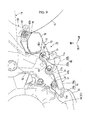
Fig. 1 is a left side view showing a motorcycle in an embodiment of the present invention. -
Fig. 2 is a left side view showing a circumference of a pivot bracket of the motorcycle. -
Fig. 3 is a left side view showing a circumference of an exhaust device in the vicinity of the pivot bracket. -
Fig. 4 is a bottom view showing the circumference of the exhaust device. -
Fig. 5 is a rear view showing the circumference of the exhaust device. -
Fig. 6 is a top view showing a servo motor stay of the exhaust device. -
Fig. 7 is a left side view showing the servo motor stay. -
Fig. 8 is a bottom view equivalent toFig. 4 showing an example that a canister is supported by the servo motor stay. -
Fig. 9 is a perspective view showing a circumference of a weight on the left side of a lower part of a vehicle body of the motorcycle. -
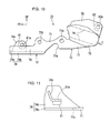
Fig. 10 is a left side view showing the weight. -
Fig. 11 is a top view showing a main part of the weight. -
Fig. 12 is a front view showing the main part of the weight. -
Fig. 13 is a view viewed from a direction shown by an arrow Z inFig. 10 . -
Fig. 14 is a left side view showing the circumference of the weight. -
Fig. 15 is a sectional view viewed along a line A-A inFig. 14 . -
Fig. 16 is a bottom view showing a front fender of the motorcycle. -
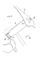
Fig. 17 is a perspective view showing the inside of the front fender. - Referring to the drawings, an embodiment of the invention will be described below. A direction such as a longitudinal direction and a lateral direction in the following description shall be the same as a vehicular direction unless special description is made. Besides, an arrow FR in the drawing points to the front side of a vehicle, LH points to the left of the vehicle, and UP points to the upside of the vehicle.
- As shown in
Fig. 1 , afront wheel 2 of a motorcycle (a saddle-ride type vehicle) 1 is journaled to each lower end of a pair of right andleft front forks 3 and an upper part of eachfront fork 3 is steerably journaled to a head pipe 6 at a front end of abody frame 5 via asteering stem 4. Ahandlebar 7 is attached onto atop bridge 4a of thesteering stem 4. - As also shown in
Fig. 4 , arear wheel 15 of the motorcycle 1 is journaled to a rear end of aswing arm 14 and a front end of theswing arm 14 is vertically swingably journaled to apivot frame 9 in a rear part of thebody frame 5 and others. Arear cushion 16 is arranged between a front part of theswing arm 14 and the rear part of thebody frame 5. - The
body frame 5 is formed by integrally bonding plural types of steel products (or castings) by welding and others and is a so-called monobackbone type acquired by extending onemain frame 8 backward from the head pipe 6 to thepivot frame 9. - The
main frame 8 is extended backward, passing the upside of an engine (an internal combustion engine) 17 mounted inside thebody frame 5, is curved downward, and is led and connected to an upper end of the vertically extendedpivot frame 9 in an intermediate part in a longitudinal direction of a vehicle body. Themain frame 8 and thepivot frame 9 are arranged in the center in a direction of vehicle width (a lateral direction) like the head pipe 6. A line CL in the drawing shows a lateral center line of the vehicle body. - A pair of right and left
pivot brackets 12 is attached on both right and left sides of thepivot frame 9 with the pivot frame laterally held between the pivot brackets. Each front end of aseat rail 13 and asupport pipe 13a for the seat rail is attached on the rear upside of themain frame 8. - The
body frame 5 is acquired by separately configuring a front piece forming the circumference of the head pipe 6, a center piece forming themain frame 8 and a rear piece forming the circumference of thepivot frame 9 by aluminum casting for example and integrally welding the pieces. The right and leftpivot brackets 12 configuring a part of thebody frame 5 are also formed by aluminum casting like each piece and are integrally fastened and fixed to thepivot frame 9 by a bolt and others. - As shown in
Figs. 2 to 4 , a pivot part (not shown) which apivot 12d of theswing arm 14 pierces is provided on the front side of a vertically intermediate part of thepivot frame 9, and left and rightarm pivot parts 14d separately provided to each front end of left andright arms swing arm 14 are respectively adjacently arranged outside the pivot part in the direction of vehicle width. -
Outer pivot parts 12c provided to the right and leftpivot brackets 12 are respectively adjacently arranged outside the right and leftarm pivot parts 14d in the direction of vehicle width. The front end of theswing arm 14 is vertically swingably journaled to thebody frame 5 by piercing each pivot part with thepivot 12d laterally directed and coupling each pivot part. Areference sign 14c denotes a cross member that couples the fronts of the left andright arms swing arm 14. - As shown in
Fig. 1 , theengine 17 is a parallel 4-cylinder engine having a rotational axis of a crank in the direction of vehicle width and has basic configuration in which acylinder 19 is planted on acrankcase 18 diagonally forward and upward. Each of fourthrottle bodies 21 is connected to the rear of eachcylinder 19 and each of fourexhaust pipes 22 is similarly connected to the front of eachcylinder 19. - Each
throttle body 21 is connected to an aircleaner case 25 arranged at the back of each throttle body. Areference sign 26 denotes an intake duct arranged along the left side of theair cleaner case 25 and open to the rear of the vehicle. - As also shown in
Fig. 4 , eachexhaust pipe 22 is suitably curved in front of theengine 17, reaches the downside of thecrankcase 18, after the right and left two pipes are integrated on both sides of the downside of thecrankcase 18 to be apreparatory collecting pipe 22a, the preparatory collecting pipes are integrated to be one pipe at the back of the right side of the downside of thecrankcase 18 to be a collectingpipe 22b. The collectingpipe 22b is connected to a connectingpipe 23a at a front end of asilencer 23 arranged on the right side of therear wheel 15. The connectingpipe 23a at the front end forms a part of theexhaust pipe 22. - The front of the collecting
pipe 22b passes the downside of theright pivot bracket 12 and anexhaust catalyst 22c is built in the front of the collectingpipe 22b. - As shown in
Fig. 1 , a pair of right and leftengine hangers 11 is tilted just from the back of the head pipe 6 mutually separately and are extended downward. Aradiator 24 tilted forward along the engine hangers is arranged just in front of the right and leftengine hangers 11. Areserve tank 24a of theradiator 24 is arranged at the back of the pivot frame 9 (seeFigs. 3 and4 ). - As the
engine 17 is supported by a supportingplate 11 a via which the front of thecylinder 19 is fixed to a lower part of theengine hanger 11 and an upper part and a lower part of the rear of thecrankcase 18 are supported by an upperpart supporting bracket 12a and a lowerpart supporting bracket 12b respectively fixed to an upper part and a lower part of thepivot frame 9, theengine 17 is supported by thebody frame 5. - The rotational driving force of the
engine 17 is output to adrive sprocket 29a on the left side of the rear of thecrankcase 18 via a clutch mechanism and a transmission respectively not shown and is transmitted to therear wheel 15 via adrive chain 29b and a drivensprocket 29c. - A
fuel tank 31 is arranged over theengine 17 across themain frame 8. Aseat 32a for a rider and atandem seat 32b for a rear pillion passenger are arranged longitudinally at the back of thefuel tank 31. Astep 32c for the rider is arranged below theseat 32a and a tandem step 32d for the rear pillion passenger is arranged below thetandem seat 32b. - As also shown in
Fig. 2 , a front end of astep bracket 33 that longitudinally supports eachstep 32c, 32d is attached to the rear of thepivot bracket 12. Thestep bracket 33 is integrated by casting using aluminum alloy materials for example and is provided at the back of thepivot bracket 12 in a state in which the step bracket is tilted backward and upward. - The front 33a of the
step bracket 33 is in a substantial V shape open forward in a side view, and upper and lower front ends of the front are fastened and fixed to upper and lower parts of a rear edge of thepivot bracket 12 by a bolt inserted from the outside in the direction of vehicle width. A frontstep supporting part 33b that tiltably supports thestep 32c for the rider is integrated with the downside of the front 33a of thestep bracket 33 and afront heel plate 33c for touching to the circumference of the heel of a foot put on thestep 32c from the inside in the direction of vehicle width is integrated with the upside of the front 33a of thestep bracket 33. - The rear 33d of the
step bracket 33 is extended backward and upward from a rear end of the front 33a with the rear tilted, a rearstep supporting part 33e that tiltably supports the tandem step 32d for the rear pillion passenger is integrated with a rear end of the rear, and arear heel plate 33f for touching to the circumference of the heel of a foot put on the tandem step 32d from the inside in the direction of vehicle width is integrated with the rear end. - A
shift pedal 27 for shifting the transmission in the rear of thecrankcase 18 is arranged in front of theleft step 32c. Theshift pedal 27 is provided with abody 27a of the pedal which can be operated by a rider's left foot put on theleft step 32c outside its rear end (its end) and is turnably supported by apedal supporting part 27b a front end (a base) of which is extended on the front side of alower part 12b of thepivot bracket 12. - A
shift spindle 27c is protruded from the left side of the rear of thecrankcase 18 and a front end (a base) of ashift lever 27d is fitted and fixed to theshift spindle 27c. An upper end of ashift rod 27e is turnably coupled to a rear end (an end) of theshift lever 27d and a lower end of theshift rod 27e is turnably coupled to an intermediate part in the longitudinal direction of theshift pedal 27. Hereby, theshift pedal 27 and theshift spindle 27c are linked and the shift is enabled. - As shown in
Figs. 2 and5 , aside stand 41 that supports the vehicle body which stands with the vehicle body tilted on the left side is provided on the left side of a lower part of the vehicle body. - The side stand 41 is turnably (storably) supported by a
lower part 42b of a flatside stand bracket 42 fastened and fixed to a lower end of theleft pivot bracket 12 by a longitudinal pair ofbolts 43 via apivot bolt 44 tilted so that the outside in the direction of vehicle width of it is located uppermost.Fig. 2 shows a stored state in which the side of an end of the side stand 41 is sprung up backward. - Outside a base of the
side stand 41, arotary switch 41 a that detects the side stand is stored or stands is provided coaxially with thepivot bolt 44. An operatingrod 41 b is extended from the outside of the end of the side stand 41 and areturn spring 41 c is arranged outside the base of theside stand 41. - The side stand
bracket 42 is made of a thick steel plate, itsupper part 42a functions as a part fixed to the vehicle body which is formed into a plate shape perpendicular to the lateral direction and is fastened to the lower end of theleft pivot bracket 12 from the outside in the direction of vehicle width, and thelower part 42b diagonally extended from a lower part of the part fixed to the vehicle body downward and outside in the direction of vehicle width functions as a stand supporting part. Thelower part 42b of the side standbracket 42 is held in the forked base of the side stand 41 in a direction of its thickness, in this state, thepivot bolt 44 pieces the lower part and the base, and the pivot bolt turnably couples them. - As shown in
Figs. 2 and4 , a main stand (a center stand) 45 that supports the vehicle body in an upright state is provided in the lower part of the vehicle body. - The
main stand 45 is mainly configured by a pair of left andright legs cross member 45c that couples respective intermediate parts of the left andright legs right legs main stand support 46 formed at a lower end of thepivot frame 9 by alateral pivot bolt 47 and accordingly, themain stand 45 is turnably (storably) supported by themain stand support 46.Fig. 2 shows a stored state in which the side of an end of themain stand 45 is sprung up backward.Reference signs 45a', 45b' shown inFig. 4 denote left and right legs in a state in which themain stand 45 is upright (a vehicle body supporting state). - The left and
right legs stand operating arm 45d is extended from the outside of the end of theleft leg 45a and astand return spring 45e is arranged outside the base of theleft leg 45a. - As shown in
Fig. 1 , afront cowl 34 that covers the circumference of the head pipe 6 from the front side across both sides is provided to the front of the vehicle body. Aheadlight 35 is arranged at a front end of thefront cowl 34, eachfront winker 36 is arranged on both sides of a lower part of thefront cowl 34, ameter unit 37 is arranged inside an upper part of thefront cowl 34, and eachrear view mirror 38 is arranged on both sides of the upper part of thefront cowl 34. Areference sign 34a denotes a windscreen and 85 denotes a front fender that covers an upper part of thefront wheel 2. - As shown in
Figs. 3 to 5 , the motorcycle 1 is provided with anexhaust device 50 that varies the area of a flow path in the exhaust pipe 22 (the collectingpipe 22b, the connectingpipe 23a at the front end in this embodiment). - The
exhaust device 50 is mainly configured by anexhaust valve 51 built in the exhaust pipe 22 (in the connectingpipe 23a at the front end) and anactuator 55 for driving theexhaust valve 51. - The
exhaust valve 51 is a butterfly valve provided with a turningshaft 52 which radially pierces the connecting pipe at thefront end 23a. The turningshaft 52 is tilted so that the inside in the direction of vehicle width is located up and a drivenpulley 53 adjacently arranged inside the connectingpipe 23a at the front end in the direction of vehicle width is fixed to an inner end in the direction of vehicle width of the turningshaft 52. The drivenpulley 53 is covered with ahousing 54 integrated with the inside in the direction of vehicle width of the connectingpipe 23a at the front end. One ends of two driving cables (hereinafter merely called cables) 59 extended from theactuator 55 are connected to the drivenpulley 53. - The
actuator 55 is located on the downside of the front of theswing arm 14 in a side view of the vehicle body and is provided with the actuator biased on the left side based upon the center line CL of the vehicle body in a bottom view of the vehicle body. More detailedly, theactuator 55 is located between the center line CL of the vehicle body and theleft arm 14a of theswing arm 14 in the lateral direction in the bottom view of the vehicle body and is located between thecross member 14c of theswing arm 14 and thepivot frame 9 in the longitudinal direction. In the meantime, the exhaust valve 51 (the connectingpipe 23a at the front end, the collectingpipe 22b) is provided with the exhaust valve biased on the right side based upon the center line CL of the vehicle body in the bottom view of the vehicle body. - The
actuator 55 is mainly configured by aservo motor 56 provided with a drivingshaft 57 arranged substantially vertically and a drivingpulley 58 fixed to an upper end of the drivingshaft 57. The other end of eachcable 59 is connected to the drivingpulley 58, the driving force of theservo motor 56 is transmitted to theexhaust valve 51 via eachcable 59, and the driving force normally and reversely rotates the exhaust valve. - After each
cable 59 is extended backward from the drivingpulley 58 at an upper end of theactuator 55 biased on the left side of the vehicle body, it is extended rightward, being suitably curved on the downside of thecross member 14c of theswing arm 14 and is coupled to the drivenpulley 53 arranged inside theexhaust pipe 22 on the right side of the vehicle body in the direction of vehicle width from the front side and from the inside in the direction of vehicle width. - The actuator 55 (the servo motor 56) is supported by the left side of a lower part of the
body frame 5 via aservo motor stay 60. - As also shown in
Figs. 6 and7 , the servo motor stay 60 is formed by integrating plural steel plates by welding and others. The servo motor stay is mainly configured by abeam part 62 extended forward from apart 61 fastened to the vehicle body (hereinafter merely called a fastened part) fastened to a bottom of theleft pivot bracket 12 and extended backward, detouring inside in the direction of vehicle width, a servo motor attachment (hereinafter merely called a motor attachment) 63 provided to the rear of thebeam part 62 and adetent 64 extended forward from themotor attachment 63 and coupled to a left end of themain stand support 46 at the lower end of thepivot frame 9. - The
beam part 62 is formed by bending a round steel pipe. The outside in the direction of vehicle width of the front of thebeam part 62 has double pipe structure in which an inner pipe is built and the flat and substantially horizontal fastenedpart 61 is formed by vertically pressing and squashing the part. - The
beam part 62 is provided with a front outside-extended part 62a diagonally extended forward from the fastenedpart 61 and inside in the direction of vehicle width, a front inside-extended part 62b diagonally extended backward from an inner end in the direction of vehicle width of the front outside-extended part 62a and inside in the direction of vehicle width, an intermediateextended part 62c extended backward from an inner end in the direction of vehicle width of the front inside-extended part 62b along the center line CL of the vehicle body and a rearextended part 62d diagonally extended backward from a rear end of the intermediateextended part 62c and outside in the direction of vehicle width. - The front outside-
extended part 62a is provided in a tilted state in which the outside in the direction of vehicle width is located up so that the fastenedpart 61 is displaced on the respective upsides of the substantially horizontal front inside-extended part 62b and the substantially horizontal front of the intermediateextended part 62c. The rear of the intermediateextended part 62c is provided in a state in which the rear is gently cranked in a side view so that the rearextended part 62d is displaced on the upside of the substantially horizontal front. The rearextended part 62d is substantially horizontally provided. - The
motor attachment 63 is formed by bending a steel plate. Themotor attachment 63 is provided with a flat lowerhorizontal plate 65a substantially horizontally extended outside in the direction of vehicle width from a lower edge of thebeam part 62 across the rear of the intermediateextended part 62c and the rearextended part 62d, a rearextended part 65b extended outside in the direction of vehicle width from an outer end in the direction of vehicle width of the rear of the lowerhorizontal plate 65a, a rearvertical plate 65c substantially vertically extended upward from an outer end in the direction of vehicle width of the rearextended part 65b and a rearhorizontal plate 65d substantially horizontally extended inside in the direction of vehicle width from an upper end of the rearvertical plate 65c. - In addition, the
motor attachment 63 is provided with an intermediateextended part 66b extended outside in the direction of vehicle width from an outer end in the direction of vehicle width of a longitudinal intermediate part of the lowerhorizontal plate 65a, avertical plate 66c substantially vertically extended upward from an outer end in the direction of vehicle width of the intermediateextended part 66b, a middlehorizontal plate 66d substantially horizontally extended outside in the direction of vehicle width from an upper end of thevertical plate 66c, an uppervertical plate 66e substantially vertically extended upward from an outer end in the direction of vehicle width of the middlehorizontal plate 66d and an upperhorizontal plate 66f substantially horizontally extended inside in the direction of vehicle width from an upper end of the uppervertical plate 66e. - The intermediate
extended part 66b is tilted so that the outside in the direction of vehicle width is located up. The longitudinal width of thevertical plate 66c is increased forward, compared with that of the intermediateextended part 66b. The uppervertical plate 66e is extended with the upper vertical plate tilted so that the upside is located in the rear in a side view. Aweld nut 66g is joined to a top face of the upperhorizontal plate 66f and a lower end of alocking pin 65e protruded upward is joined to the rearhorizontal plate 65d. Each longitudinal width of the upperhorizontal plate 66f and the rearhorizontal plate 65d is substantially equal, each central position of theweld nut 66g and thelocking pin 65e is substantially equal in the longitudinal direction, and further, the lockingpin 65e is provided with the locking pin displaced inside in the direction of vehicle width for theweld nut 66g. - A front
extended part 67b is provided in front of thevertical plate 66c and an upperextended part 67c is provided in front of the middlehorizontal plate 66d. A round pipe joint 67d in the shape of a semicircle in a side view is provided to a front end of the frontextended part 67b and the periphery of a cylindricalshort pipe 67e extended in the direction of vehicle width is joined to an inner face of the round pipe joint 67d. A cylindrical pipe bush (rubber bush) 67f similarly extended in the direction of vehicle width is fitted and held into theshort pipe 67e. Thedetent 64 is configured by the frontextended part 67b, the upperextended part 67c, the round pipe joint 67d, theshort pipe 67e and thepipe bush 67f. A central position of thepipe bush 67f is located up in a side view, compared with the fastenedpart 61 and is located at the back of the fastenedpart 61 and inside the fastened part in the direction of vehicle width in a bottom view. - As shown in
Figs. 3 to 5 , a substantially horizontal thick lower supportedpart 56a and an intermediate supportedpart 56c respectively protruded backward are provided to a lower end and to a vertically intermediate part respectively on the rear side of the actuator 55 (the servo motor 56). Thelocking pin 65e of the rearhorizontal part 65d pierces the lower supportedpart 56a via arubber bush 56b from the downside and thereby, the lower supportedpart 56a is elastically supported on the rearhorizontal plate 65d. In the meantime, a bolt screwed to theweld nut 66g of the upperhorizontal plate 66f pierces the intermediate supportedpart 56c via arubber bush 56d from the downside and thereby, the intermediate supportedpart 56c is elastically supported under the upperhorizontal plate 66f. Hereby, theactuator 55 is mounted on themotor attachment 63 via rubber. - A front end (the
pipe bush 67f) of thedetent 64 is adjacent to the left end of themain stand support 46 at the lower end of thepivot frame 9 and the front end of thedetent 64 is elastically supported by the lower end of thepivot frame 9 by making thepivot bolt 47 of themain stand 45 pierce and support thepipe bush 67f. - In such attachment, the
servo motor 56 is arranged so that the servo motor is overlapped with the left side of the lower part of thepivot frame 9 in a rear view and is arranged between theexhaust pipe 22 and theswing arm 14 in a side view. - The
servo motor 56 is supported by thebody frame 5 mainly via the cantilever-type beam part 62 a front end of which is fastened and fixed to thebody frame 5, however, as the rear of thebeam part 62 is elastically supported by thebody frame 5 via themotor attachment 63 formed by bending a plate member and thedetent 64, the whirl of the servo motor stay 60 is stopped and the vibration of the rear (a circumference of the servo motor 56) of the servo motor stay 60 is inhibited. As theservo motor 56 is mounted on the servo motor stay 60 via rubber, the transmission to the servo motor stay 60 of the vibration of theservo motor 56 is also inhibited. - The
beam part 62 of the servo motor stay 60 is arranged between the left andright legs main stand 45. Hereby, the turning of themain stand 45 is prevented from being obstructed by theservo motor 56 and theservo motor stay 60 and theservo motor 56 is arranged in dead space on the upside of themain stand 45 and between the left andright legs - A servo motor cover (hereinafter merely called a motor cover) 69 made of an elastic member such as rubber is detachably mounted on the
actuator 55. Themotor cover 69 covers the outside faces of most except the supportedparts servo motor 56 via predetermined interference and turnably covers the drivingpulley 58 via predetermined clearance. An effect of disturbance on theactuator 55 arranged in the lower part of the vehicle body is reduced owing to themotor cover 69. Aweight 70 supported by a circumference of a lower end of a left pivot plate is arranged outside theactuator 55 in the direction of vehicle width and as the actuator is covered with theweight 70 from the outside in the direction of vehicle width, the effect of disturbance on theactuator 55 is also reduced. - A front end of a
cable holder 67g formed by bending a wire-like steel product so as to hold eachcable 59 extended from theservo motor 56 is joined to a rear end of thebeam part 62. Aclip 56g is provided to a bottom of acoupler 56f at an end of apower supply harness 56e extended from theservo motor 56, and aclip hole 56h for engaging theclip 56g is formed in the front of the lowerhorizontal plate 65a of themotor attachment 63. -
Fig. 8 shows an example that acanister 68 is supported by the rear of the servo motor stay 60 together with theservo motor 56 as a transformed example of this embodiment. - The
canister 68 is evaporated fuel treating equipment that scavenges fuel gas evaporated in thefuel tank 31, absorbs fuel evaporated in thefuel tank 31, while the canister supplies the absorbed fuel to an intake path when theengine 17 is operated so as to combust the fuel in thecylinder 19. Thecanister 68 has substantially cylindrical appearance and is adjacently arranged along the rearextended part 62d of thebeam part 62. - A
canister supporting plate 68a is joined to the right side of the rearextended part 62d across the center line CL of the vehicle body and thecanister 68 is supported on thecanister supporting plate 68a. Areference sign 68b in the drawing denotes a fuel supply hose (a purge hose) to the intake path, 68c denotes an open hose that makes a fuel absorbing part in thecanister 68 and the air communicate, 68d denotes a drain hose, and 68e denotes a hose for taking in evaporated fuel from the fuel tank 31 (a charge hose). - As shown in
Figs. 2 and9 , theflat weight 70 substantially perpendicular to the lateral direction is arranged outside theservo motor 56 in the direction of vehicle width. - The
weight 70 is fastened and fixed to the lower end of theleft pivot bracket 12 together with the side standbracket 42 and is provided with a part attached to thevehicle body 71 having ahole 71 b for inserting thebolt 43, afront overhang 72 extended in front of the part attached to the vehicle body and arear overhang 73 extended at the back of the part attached to the vehicle body. - As also shown in
Figs. 10 to 13 , theweight 70 is mainly configured by amain plate member 74 from a front end of the weight to a rear end and asubplate member 75 integrated with the outside in the direction of vehicle width of the rear (the rear overhang 73) of themain plate member 74. - The
main plate member 74 is formed by bending a thick steel plate and is provided with avertical wall 74a substantially perpendicular to the lateral direction and alateral wall 74b substantially horizontally extended inside in the direction of vehicle width from a lower edge of the front of thevertical wall 74a. The part attached to thevehicle body 71 is equivalent to a longitudinal intermediate part (a longitudinal intermediate part of the weight 70) of thevertical wall 74a. A downward recessedportion 71 a for avoiding aspring locking pin 42c of the side standbracket 42 is formed at a lower edge of the part attached to thevehicle body 71. An upper edge of the part attached to thevehicle body 71 is formed into a recessed shape along a contour of the lower end of theleft pivot bracket 12. - A front
extended part 76 is connected in front of a lower part of the part attached to thevehicle body 71 and the substantially trapezoidallateral wall 74b in a top view is substantially horizontally extended inside in the direction of vehicle width from a lower edge of the frontextended part 76. In the meantime, a rearextended part 77 is connected at the back of the part attached to thevehicle body 71 and a substantially square upperextended part 78 in a side view is connected on the upside of the rearextended part 77. Thesubplate member 75 is joined across the upper extended part and the rear extended part outside the upperextended part 78 and the rearextended part 77 in the direction of vehicle width. The upperextended part 78, the rearextended part 77 and thesubplate member 75 are gently cranked so that each upper part is displaced outside in the direction of vehicle width so as to form upper and lowerbent lines 79 the rears of which are located up. - The
front overhang 72 is elastically supported by theleft pivot bracket 12 by touching the front overhang to the lower end of theleft pivot bracket 12 via afront rubber member 81 from the inside in the direction of vehicle width. In the meantime, therear overhang 73 is elastically supported by theleft step bracket 33 by touching the rear overhang to theleft step bracket 33 via arear rubber member 82 from the inside in the direction of vehicle width. - A slightly projecting and V-type
front supporting bracket 74c is joined to a top face of thelateral wall 74b in the front and outside in the direction of vehicle width in a top view and a front mountinghole 81 a for mounting thefront rubber member 81 is formed on the sidewall substantially perpendicular to the direction of vehicle width of the front supportingbracket 74c. In the meantime, arear mounting hole 82a for mounting therear rubber member 82 is formed on the rear side of an upper part of the upperextended part 78. - As shown in
Figs. 14 and15 , theweight 70 is supported by the left side of the lower part of the vehicle body by jointly fastening the part attached to thevehicle body 71 to the lower end of theleft pivot bracket 12 together with the side standbracket 42 in a state in which the part attached to the vehicle body is held between the lower end of theleft pivot bracket 12 and theupper part 42a of the side standbracket 42, by pressure-welding thefront rubber member 81 to a frontcushion pressing part 81 b formed on the front side of the lower end of theleft pivot bracket 12 from the inside in the direction of vehicle width and by pressure-welding therear rubber member 82 to a rearcushion pressing part 82b on the downside of the front 33a of theleft step bracket 33 from the inside in the direction of vehicle width. - Hereby, in the
weight 70 provided with the front andrear overhangs vehicle body 71, the vibration of the front andrear overhangs - An upper edge of the subplate is formed into a recessed shape along a lower edge of the front 33a located just up of the
left step bracket 33 and contributes to the formation of the integral appearance in a side view of a circumference of theweight 70 and securing the weight. - As shown in
Figs. 16 and17 , thefront fender 85 is fastened and fixed to the front and the rear of an upper end of each bottom case (each outer tube) of the right and leftfront forks 3 by front and rear bolts B. Inside thefront fender 85, a reinforcingstay 87 that couples the rears of the right and leftfront forks 3 is provided. The reinforcingstay 87 is made of iron and steel differently from the syntheticresin front fender 8, is a band laid between the right and leftfront forks 3, and is curved along the tread of the front wheel 2 (an inner face of the front fender 85). Right and left ends of the reinforcingstay 87 are in the shape of a plate substantially perpendicular to the lateral direction and eachcollar 88a of right and leftnuts 88 pierces each right and left end. The reinforcingstay 87 is fixed together with thefront fender 85 in a state in which the reinforcing stay couples the right and leftfront forks 3 by screwing the rear bolt into thecollar 88a from the outside in the direction of vehicle width and tightening it. - As described above, the servo motor layout structure of the saddle-ride type vehicle in this embodiment is applied to the motorcycle 1 provided with the
engine 17 supported by thebody frame 5, theswing arm 14 the front end of which is swingably supported by at least either of thebody frame 5 or theengine 17 and the rear end of which journals therear wheel 15, theexhaust pipe 22 connected to theengine 17, theexhaust valve 51 provided in theexhaust pipe 22, theservo motor 56 that drives theexhaust valve 51 and thecable 59 that couples theexhaust valve 51 and theservo motor 56, and theexhaust valve 51 and theservo motor 56 are arranged on the downside of theswing arm 14 in the side view. - According to this configuration, the length and the curvature of the
cable 59 that couples theexhaust valve 51 and theservo motor 56 can be inhibited, arranging theexhaust valve 51 and theservo motor 56 in the dead space on the downside of theswing arm 14. - Besides, the servo motor layout structure is provided with the servo motor stay 60 that supports the
servo motor 56 by thebody frame 5, and the servo motor stay 60 is provided with thebeam part 62 the front of which is fastened to the lower part of thebody frame 5, theservo motor attachment 63 provided to the rear of thebeam part 62 and thedetent 64 extended forward from theservo motor attachment 63 and coupled to the lower part of thebody frame 5 at the back of thepart 61 fastened to the vehicle body of thebeam part 62. - According to this configuration, though the
servo motor 56 is required to be supported by a cantilever if no supporting part is especially formed on thebody frame 5 when theservo motor 56 is arranged on the downside of theswing arm 14, theservo motor 56 can be stably and securely supported by thebody frame 5 by using the servo motor stay 60 provided with thebeam part 62 and thedetent 64 positions for mounting them on thebody frame 5 of which are different in the longitudinal direction. - In addition, in the servo motor layout structure, the
main stand support 46 that journals themain stand 45 is provided to the lower part of thebody frame 5 and thedetent 64 of the servo motor stay 60 is fastened to the stand swinging shaft (the pivot bolt 47) in themain stand support 46 via thepipe bush 67f. - According to this configuration, even if no mounting part is separately provided to the
body frame 5, thedetent 64 can be coupled to themain stand support 46. As thedetent 64 is elastically supported via thepipe bush 67f even if the servo motor stay 60 is vertically vibrated due to irregularities of a road surface and others, vibration transmitted to themain stand support 46 can be reduced and a state in which thedetent 64 is supported can be more securely maintained. - Besides, in the servo motor layout structure, the
main stand 45 is provided with the pair of left andright legs beam part 62 of the servo motor stay 60 is longitudinally extended passing between the left andright legs main stand support 46, and the front is fastened to the bottom of thebody frame 5. - According to this configuration, even if the
main stand 45 is stood or is stored, the servo motor stay 60 can be attached to thebody frame 5 with thebeam part 62 avoiding the left andright legs - In addition, in the servo motor layout structure, the servo motor stay 60 is provided with the plate member (the servo motor attachment 63) made by bending a steel plate, the plate member is provided with the substantially horizontal lower
horizontal plate 65a, thevertical plates horizontal plate 65a, the pipe bush mounting part (the round pipe joint 67d, theshort pipe 67e) provided in front of thevertical plates horizontal plates vertical plates vertical plates detent 64, and theservo motor 56 is mounted on thehorizontal plates - According to this configuration, the servo motor stay 60 can be provided at a low cost with simple configuration by bending the plate member and forming the
detent 64 and the rubber mounting part (thehorizontal plates servo motor 56. As thedetent 64 is made of the plate, it is not bulky and the servo motor stay 60 can be compacted. - Besides, in the servo motor layout structure, the coupler locking hole (the
clip hole 56h) for locking the coupler check member (theclip 56g) provided to thecoupler 56f of theservo motor 56 is provided to the lowerhorizontal plate 65a. - According to this configuration, as the lower
horizontal plate 65a is made of a plate, the coupler locking hole can be easily provided. - In addition, in the servo motor layout structure, the
canister supporting plate 68a is further provided to theservo motor stay 60. - According to this configuration, the
canister 68 can be also supported by the servo motor stay 60 in the dead space under theswing arm 14. - Besides, in the servo motor layout structure, the rubber
servo motor cover 69 is mounted on theservo motor 56. - According to this configuration, an effect of disturbance such as a splash from a road surface on the
servo motor 56 arranged under theswing arm 14 can be inhibited. - Further, in the servo motor layout structure, the
weight 70 is provided to thebody frame 5 with the weight covering the side of theservo motor 56. - According to this configuration, the
weight 70 excellent in strength and rigidity can also function as a cover that covers the side of theservo motor 56. - Furthermore, in the servo motor layout structure, the
servo motor 56 is provided with the servo motor biased on one side based upon the center line CL of the vehicle body in the bottom view of the vehicle body and theexhaust valve 51 is provided with the exhaust valve biased on the other side based upon the center line CL of the vehicle body in the bottom view of the vehicle body. - According to this configuration, the
servo motor 56 is separated from the exhaust pipe 22 (the collectingpipe 22b) and the heat of theexhaust pipe 22 can be prevented from having an effect on theservo motor 56. - This invention is not limited to the above-mentioned embodiment, for example, this invention can be also applied to a three-wheeled or four-wheel saddle-ride type vehicle in addition to a motorcycle, and it need scarcely be said that various changes are allowed in a range in which they do not deviate from the substance of this invention.
- The present invention is directed to efficiently arrange a servo motor in a place except the downside of a seat, inhibiting the length and the curvature of a cable in servo motor layout structure of a saddle-ride type vehicle provided with the servo motor for driving an exhaust valve.
- A
swing arm 14 a front end of which is swingably supported by at least either a body frame or an engine and a rear end of which journals a rear wheel is provided and anexhaust valve 51 and aservo motor 56 are arranged on the downside of theswing arm 14 in a side view.
Claims (10)
- Servo motor layout structure of a saddle-ride type vehicle (1) comprising:an engine (17) supported by a body frame (5);a swing arm (14) a front end of which is swingably supported by at least either of the body frame (5) or the engine (17) and a rear end of which journals a rear wheel (15);an exhaust pipe (22) connected to the engine (17);an exhaust valve (51) provided in the exhaust pipe (22);a servo motor (56) that drives the exhaust valve (51); anda cable (59) that couples the exhaust valve (51) and the servo motor (56),wherein the exhaust valve (51) and the servo motor (56) are arranged on the downside of the swing arm (14) in a side view.
- The servo motor layout structure of the saddle-ride type vehicle (1) according to Claim 1, comprising a servo motor stay (60 that assists the servo motor (56) to be supported by the body frame (5),
wherein the servo motor stay (60) has:a beam part (62) the front of which is fastened to a lower part of the body frame (5);a servo motor attachment (63) provided to the rear of the beam part (62); anda detent (64) extended forward from the servo motor attachment (63) and coupled to the lower part of the body frame (5) at the back of a part fastened to a vehicle body of the beam part (63). - The servo motor layout structure of the saddle-ride type vehicle (1) according to Claim 2,
wherein: a main stand support (46) that journals a main stand (45) is provided to the lower part of the body frame (5); and
the detent (64) of the servo motor stay (60) is fastened to a stand swinging shaft (47) in the main stand support (46) via a pipe bush (67f). - The servo motor layout structure of the saddle-ride type vehicle (1) according to Claim 3,
wherein: the main stand (45) is provided with a pair of right and left legs (45a, 45b);
the beam part (62) of the servo motor stay (60) is longitudinally extended passing between the right and left legs (45a, 45b); and
the front of the beam part (62) is curved on one side in a direction of vehicle width in front of the main stand support (46) and is fastened to a bottom of the body frame (5). - The servo motor layout structure of the saddle-ride type vehicle (1) according to any of Claims 2 to 4,
wherein: the servo motor stay (60) is provided with a plate member (63) formed by bending a steel plate;
the plate member (63) is provided with a substantially horizontal lower horizontal plate (65a), a vertical plate (65c) substantially vertically bent from one side edge of the lower horizontal part (65a), a pipe bush (67f) mounting part provided in front of the vertical plate (65c) and an upper horizontal plate (65d) substantially horizontally bent from an upper edge of the vertical plate (65c);
the vertical plate (65c) is extended forward to form the detent (64); and
the servo motor (56) is mounted on the upper horizontal plate (65d) via rubber. - The servo motor layout structure of the saddle-ride type vehicle (1) according to Claim 5, wherein a coupler locking hole (56h) for locking a coupler check member (56g) provided to a coupler of the servo motor (56) is provided to the lower horizontal plate (65a).
- The servo motor layout structure of the saddle-ride type vehicle (1) according to any of Claims 2 to 6, wherein a canister mounting part (68a) is further provided to the servo motor stay (60).
- The servo motor layout structure of the saddle-ride type vehicle (1) according to any of Claims 1 to 7, wherein a rubber servo motor cover (69) is mounted on the servo motor (56).
- The servo motor layout structure of the saddle-ride type vehicle (1) according to any of Claims 1 to 8, wherein a weight (70) is provided to the body frame (5) with the weight (70) covering a side of the servo motor (56).
- The servo motor layout structure of the saddle-ride type vehicle (1) according to any of Claims 1 to 9,
wherein: the servo motor (56) is provided with the servo motor (56) biased on one side based upon a center line (CL) of the vehicle body in a bottom view of the vehicle body; and
the exhaust valve (51) is provided with the exhaust valve (51) biased on the other side based upon the center line (CL) of the vehicle body in the bottom view of the vehicle body.
Applications Claiming Priority (1)
| Application Number | Priority Date | Filing Date | Title |
|---|---|---|---|
| JP2009269943A JP5256178B2 (en) | 2009-11-27 | 2009-11-27 | Servo motor arrangement structure for saddle riding type vehicles |
Publications (2)
| Publication Number | Publication Date |
|---|---|
| EP2332762A1 true EP2332762A1 (en) | 2011-06-15 |
| EP2332762B1 EP2332762B1 (en) | 2012-03-14 |
Family
ID=43302943
Family Applications (1)
| Application Number | Title | Priority Date | Filing Date |
|---|---|---|---|
| EP10177838A Not-in-force EP2332762B1 (en) | 2009-11-27 | 2010-09-21 | Servo motor layout structure of saddle-ride type vehicle |
Country Status (4)
| Country | Link |
|---|---|
| US (1) | US8297397B2 (en) |
| EP (1) | EP2332762B1 (en) |
| JP (1) | JP5256178B2 (en) |
| AT (1) | ATE549192T1 (en) |
Families Citing this family (6)
| Publication number | Priority date | Publication date | Assignee | Title |
|---|---|---|---|---|
| JP5150415B2 (en) * | 2008-08-29 | 2013-02-20 | 本田技研工業株式会社 | Motorcycle canister arrangement structure |
| JP2012001119A (en) * | 2010-06-17 | 2012-01-05 | Suzuki Motor Corp | Canister arrangement structure of motorcycle |
| JP2012136161A (en) * | 2010-12-27 | 2012-07-19 | Honda Motor Co Ltd | Saddle riding vehicle |
| JP5990206B2 (en) * | 2014-02-25 | 2016-09-07 | 本田技研工業株式会社 | Canister layout structure for saddle-ride type vehicles |
| JP2017105286A (en) * | 2015-12-08 | 2017-06-15 | スズキ株式会社 | Saddle riding vehicle |
| US10041387B2 (en) * | 2015-12-25 | 2018-08-07 | Honda Motor Co., Ltd. | Exhaust device structure for rocking vehicle |
Citations (3)
| Publication number | Priority date | Publication date | Assignee | Title |
|---|---|---|---|---|
| EP0265889A2 (en) * | 1986-10-27 | 1988-05-04 | Yamaha Motor Co., Ltd. | Exhaust gas control means for motorcycle and the like |
| EP1510673A2 (en) * | 2003-08-27 | 2005-03-02 | HONDA MOTOR CO., Ltd. | Exhaust control system for motorcycle |
| US20090008900A1 (en) * | 2007-07-05 | 2009-01-08 | Honda Motor Co., Ltd. | Step holder mounting structure of motorcycle |
Family Cites Families (5)
| Publication number | Priority date | Publication date | Assignee | Title |
|---|---|---|---|---|
| JPS63141892A (en) * | 1986-12-03 | 1988-06-14 | ヤマハ発動機株式会社 | Exhaust controller for scooter type car |
| JP2003239766A (en) * | 2002-02-15 | 2003-08-27 | Yamaha Motor Co Ltd | Exhaust device |
| JP4272029B2 (en) * | 2003-09-30 | 2009-06-03 | 本田技研工業株式会社 | Motorcycle exhaust control system |
| EP1767446B1 (en) * | 2005-09-21 | 2015-07-15 | Honda Motor Co., Ltd. | Low floor type motorcycle |
| JP4850044B2 (en) * | 2006-08-28 | 2012-01-11 | ヤマハ発動機株式会社 | Motorcycle |
-
2009
- 2009-11-27 JP JP2009269943A patent/JP5256178B2/en not_active Expired - Fee Related
-
2010
- 2010-09-21 AT AT10177838T patent/ATE549192T1/en active
- 2010-09-21 EP EP10177838A patent/EP2332762B1/en not_active Not-in-force
- 2010-11-24 US US12/954,083 patent/US8297397B2/en not_active Expired - Fee Related
Patent Citations (3)
| Publication number | Priority date | Publication date | Assignee | Title |
|---|---|---|---|---|
| EP0265889A2 (en) * | 1986-10-27 | 1988-05-04 | Yamaha Motor Co., Ltd. | Exhaust gas control means for motorcycle and the like |
| EP1510673A2 (en) * | 2003-08-27 | 2005-03-02 | HONDA MOTOR CO., Ltd. | Exhaust control system for motorcycle |
| US20090008900A1 (en) * | 2007-07-05 | 2009-01-08 | Honda Motor Co., Ltd. | Step holder mounting structure of motorcycle |
Also Published As
| Publication number | Publication date |
|---|---|
| US8297397B2 (en) | 2012-10-30 |
| US20110127098A1 (en) | 2011-06-02 |
| JP2011111065A (en) | 2011-06-09 |
| ATE549192T1 (en) | 2012-03-15 |
| EP2332762B1 (en) | 2012-03-14 |
| JP5256178B2 (en) | 2013-08-07 |
Similar Documents
| Publication | Publication Date | Title |
|---|---|---|
| JP5905091B2 (en) | Saddle riding | |
| CN102770332B (en) | Evaporated fuel control device for saddle-type vehicles | |
| JP2019119292A (en) | Abs arrangement structure for saddle-riding type vehicle | |
| US9156513B2 (en) | Front cowl stay attachment structure for saddle-ride type vehicle | |
| EP2332762B1 (en) | Servo motor layout structure of saddle-ride type vehicle | |
| JP6288524B2 (en) | Saddle riding | |
| JP5816715B2 (en) | Saddle riding | |
| US7637342B2 (en) | Straddle type vehicle | |
| JP2013071589A (en) | Saddle-type vehicle | |
| JPWO2015068187A1 (en) | Body frame structure of saddle riding type vehicle | |
| JP5667542B2 (en) | Saddle riding | |
| JP5764025B2 (en) | Saddle riding | |
| US9555850B2 (en) | Saddle-type vehicle | |
| JP5631279B2 (en) | Rear structure of saddle-ride type vehicle | |
| JP2013071598A (en) | Saddle ridding type vehicle | |
| JP4577806B2 (en) | Body structure of motorcycle | |
| US8051739B2 (en) | Vehicle-use transmission manipulating device | |
| JP5460885B2 (en) | Front structure of motorcycle | |
| JP6077827B2 (en) | Manufacturing method of resin tank for vehicle | |
| JP5139404B2 (en) | Saddle riding | |
| JP3157691U (en) | Saddle riding vehicle | |
| JP2009090891A (en) | Saddle riding vehicle | |
| JP3748470B2 (en) | Rear fender mounting structure for motorcycles | |
| JP5307497B2 (en) | Low floor saddle riding type vehicle | |
| JP2022153076A (en) | Saddle-riding type vehicle |
Legal Events
| Date | Code | Title | Description |
|---|---|---|---|
| PUAI | Public reference made under article 153(3) epc to a published international application that has entered the european phase |
Free format text: ORIGINAL CODE: 0009012 |
|
| 17P | Request for examination filed |
Effective date: 20100921 |
|
| AK | Designated contracting states |
Kind code of ref document: A1 Designated state(s): AL AT BE BG CH CY CZ DE DK EE ES FI FR GB GR HR HU IE IS IT LI LT LU LV MC MK MT NL NO PL PT RO SE SI SK SM TR |
|
| AX | Request for extension of the european patent |
Extension state: BA ME RS |
|
| GRAP | Despatch of communication of intention to grant a patent |
Free format text: ORIGINAL CODE: EPIDOSNIGR1 |
|
| RIC1 | Information provided on ipc code assigned before grant |
Ipc: B62K 11/04 20060101ALI20110901BHEP Ipc: F02D 11/10 20060101ALI20110901BHEP Ipc: B62K 19/30 20060101ALI20110901BHEP Ipc: F02D 9/04 20060101ALI20110901BHEP Ipc: B60K 5/00 20060101AFI20110901BHEP Ipc: B62M 7/02 20060101ALI20110901BHEP Ipc: B62K 25/28 20060101ALI20110901BHEP |
|
| GRAS | Grant fee paid |
Free format text: ORIGINAL CODE: EPIDOSNIGR3 |
|
| GRAA | (expected) grant |
Free format text: ORIGINAL CODE: 0009210 |
|
| AK | Designated contracting states |
Kind code of ref document: B1 Designated state(s): AL AT BE BG CH CY CZ DE DK EE ES FI FR GB GR HR HU IE IS IT LI LT LU LV MC MK MT NL NO PL PT RO SE SI SK SM TR |
|
| REG | Reference to a national code |
Ref country code: GB Ref legal event code: FG4D |
|
| REG | Reference to a national code |
Ref country code: AT Ref legal event code: REF Ref document number: 549192 Country of ref document: AT Kind code of ref document: T Effective date: 20120315 Ref country code: CH Ref legal event code: EP |
|
| REG | Reference to a national code |
Ref country code: IE Ref legal event code: FG4D |
|
| REG | Reference to a national code |
Ref country code: DE Ref legal event code: R096 Ref document number: 602010001053 Country of ref document: DE Effective date: 20120510 |
|
| REG | Reference to a national code |
Ref country code: NL Ref legal event code: VDEP Effective date: 20120314 |
|
| PG25 | Lapsed in a contracting state [announced via postgrant information from national office to epo] |
Ref country code: HR Free format text: LAPSE BECAUSE OF FAILURE TO SUBMIT A TRANSLATION OF THE DESCRIPTION OR TO PAY THE FEE WITHIN THE PRESCRIBED TIME-LIMIT Effective date: 20120314 Ref country code: NO Free format text: LAPSE BECAUSE OF FAILURE TO SUBMIT A TRANSLATION OF THE DESCRIPTION OR TO PAY THE FEE WITHIN THE PRESCRIBED TIME-LIMIT Effective date: 20120614 Ref country code: LT Free format text: LAPSE BECAUSE OF FAILURE TO SUBMIT A TRANSLATION OF THE DESCRIPTION OR TO PAY THE FEE WITHIN THE PRESCRIBED TIME-LIMIT Effective date: 20120314 |
|
| LTIE | Lt: invalidation of european patent or patent extension |
Effective date: 20120314 |
|
| PG25 | Lapsed in a contracting state [announced via postgrant information from national office to epo] |
Ref country code: FI Free format text: LAPSE BECAUSE OF FAILURE TO SUBMIT A TRANSLATION OF THE DESCRIPTION OR TO PAY THE FEE WITHIN THE PRESCRIBED TIME-LIMIT Effective date: 20120314 Ref country code: LV Free format text: LAPSE BECAUSE OF FAILURE TO SUBMIT A TRANSLATION OF THE DESCRIPTION OR TO PAY THE FEE WITHIN THE PRESCRIBED TIME-LIMIT Effective date: 20120314 Ref country code: GR Free format text: LAPSE BECAUSE OF FAILURE TO SUBMIT A TRANSLATION OF THE DESCRIPTION OR TO PAY THE FEE WITHIN THE PRESCRIBED TIME-LIMIT Effective date: 20120615 |
|
| REG | Reference to a national code |
Ref country code: AT Ref legal event code: MK05 Ref document number: 549192 Country of ref document: AT Kind code of ref document: T Effective date: 20120314 |
|
| PG25 | Lapsed in a contracting state [announced via postgrant information from national office to epo] |
Ref country code: CY Free format text: LAPSE BECAUSE OF FAILURE TO SUBMIT A TRANSLATION OF THE DESCRIPTION OR TO PAY THE FEE WITHIN THE PRESCRIBED TIME-LIMIT Effective date: 20120314 |
|
| PG25 | Lapsed in a contracting state [announced via postgrant information from national office to epo] |
Ref country code: RO Free format text: LAPSE BECAUSE OF FAILURE TO SUBMIT A TRANSLATION OF THE DESCRIPTION OR TO PAY THE FEE WITHIN THE PRESCRIBED TIME-LIMIT Effective date: 20120314 Ref country code: EE Free format text: LAPSE BECAUSE OF FAILURE TO SUBMIT A TRANSLATION OF THE DESCRIPTION OR TO PAY THE FEE WITHIN THE PRESCRIBED TIME-LIMIT Effective date: 20120314 Ref country code: PL Free format text: LAPSE BECAUSE OF FAILURE TO SUBMIT A TRANSLATION OF THE DESCRIPTION OR TO PAY THE FEE WITHIN THE PRESCRIBED TIME-LIMIT Effective date: 20120314 Ref country code: SE Free format text: LAPSE BECAUSE OF FAILURE TO SUBMIT A TRANSLATION OF THE DESCRIPTION OR TO PAY THE FEE WITHIN THE PRESCRIBED TIME-LIMIT Effective date: 20120314 Ref country code: CZ Free format text: LAPSE BECAUSE OF FAILURE TO SUBMIT A TRANSLATION OF THE DESCRIPTION OR TO PAY THE FEE WITHIN THE PRESCRIBED TIME-LIMIT Effective date: 20120314 Ref country code: SI Free format text: LAPSE BECAUSE OF FAILURE TO SUBMIT A TRANSLATION OF THE DESCRIPTION OR TO PAY THE FEE WITHIN THE PRESCRIBED TIME-LIMIT Effective date: 20120314 Ref country code: IS Free format text: LAPSE BECAUSE OF FAILURE TO SUBMIT A TRANSLATION OF THE DESCRIPTION OR TO PAY THE FEE WITHIN THE PRESCRIBED TIME-LIMIT Effective date: 20120714 Ref country code: BE Free format text: LAPSE BECAUSE OF FAILURE TO SUBMIT A TRANSLATION OF THE DESCRIPTION OR TO PAY THE FEE WITHIN THE PRESCRIBED TIME-LIMIT Effective date: 20120314 |
|
| PG25 | Lapsed in a contracting state [announced via postgrant information from national office to epo] |
Ref country code: PT Free format text: LAPSE BECAUSE OF FAILURE TO SUBMIT A TRANSLATION OF THE DESCRIPTION OR TO PAY THE FEE WITHIN THE PRESCRIBED TIME-LIMIT Effective date: 20120716 Ref country code: SK Free format text: LAPSE BECAUSE OF FAILURE TO SUBMIT A TRANSLATION OF THE DESCRIPTION OR TO PAY THE FEE WITHIN THE PRESCRIBED TIME-LIMIT Effective date: 20120314 |
|
| PLBE | No opposition filed within time limit |
Free format text: ORIGINAL CODE: 0009261 |
|
| STAA | Information on the status of an ep patent application or granted ep patent |
Free format text: STATUS: NO OPPOSITION FILED WITHIN TIME LIMIT |
|
| PG25 | Lapsed in a contracting state [announced via postgrant information from national office to epo] |
Ref country code: NL Free format text: LAPSE BECAUSE OF FAILURE TO SUBMIT A TRANSLATION OF THE DESCRIPTION OR TO PAY THE FEE WITHIN THE PRESCRIBED TIME-LIMIT Effective date: 20120314 Ref country code: DK Free format text: LAPSE BECAUSE OF FAILURE TO SUBMIT A TRANSLATION OF THE DESCRIPTION OR TO PAY THE FEE WITHIN THE PRESCRIBED TIME-LIMIT Effective date: 20120314 Ref country code: AT Free format text: LAPSE BECAUSE OF FAILURE TO SUBMIT A TRANSLATION OF THE DESCRIPTION OR TO PAY THE FEE WITHIN THE PRESCRIBED TIME-LIMIT Effective date: 20120314 |
|
| 26N | No opposition filed |
Effective date: 20121217 |
|
| REG | Reference to a national code |
Ref country code: DE Ref legal event code: R097 Ref document number: 602010001053 Country of ref document: DE Effective date: 20121217 |
|
| PG25 | Lapsed in a contracting state [announced via postgrant information from national office to epo] |
Ref country code: MC Free format text: LAPSE BECAUSE OF NON-PAYMENT OF DUE FEES Effective date: 20120930 Ref country code: ES Free format text: LAPSE BECAUSE OF FAILURE TO SUBMIT A TRANSLATION OF THE DESCRIPTION OR TO PAY THE FEE WITHIN THE PRESCRIBED TIME-LIMIT Effective date: 20120625 |
|
| REG | Reference to a national code |
Ref country code: IE Ref legal event code: MM4A |
|
| PG25 | Lapsed in a contracting state [announced via postgrant information from national office to epo] |
Ref country code: BG Free format text: LAPSE BECAUSE OF FAILURE TO SUBMIT A TRANSLATION OF THE DESCRIPTION OR TO PAY THE FEE WITHIN THE PRESCRIBED TIME-LIMIT Effective date: 20120614 Ref country code: IE Free format text: LAPSE BECAUSE OF NON-PAYMENT OF DUE FEES Effective date: 20120921 |
|
| PG25 | Lapsed in a contracting state [announced via postgrant information from national office to epo] |
Ref country code: MT Free format text: LAPSE BECAUSE OF FAILURE TO SUBMIT A TRANSLATION OF THE DESCRIPTION OR TO PAY THE FEE WITHIN THE PRESCRIBED TIME-LIMIT Effective date: 20120314 Ref country code: AL Free format text: LAPSE BECAUSE OF FAILURE TO SUBMIT A TRANSLATION OF THE DESCRIPTION OR TO PAY THE FEE WITHIN THE PRESCRIBED TIME-LIMIT Effective date: 20120314 |
|
| PG25 | Lapsed in a contracting state [announced via postgrant information from national office to epo] |
Ref country code: TR Free format text: LAPSE BECAUSE OF FAILURE TO SUBMIT A TRANSLATION OF THE DESCRIPTION OR TO PAY THE FEE WITHIN THE PRESCRIBED TIME-LIMIT Effective date: 20120314 |
|
| PG25 | Lapsed in a contracting state [announced via postgrant information from national office to epo] |
Ref country code: LU Free format text: LAPSE BECAUSE OF NON-PAYMENT OF DUE FEES Effective date: 20120921 Ref country code: SM Free format text: LAPSE BECAUSE OF FAILURE TO SUBMIT A TRANSLATION OF THE DESCRIPTION OR TO PAY THE FEE WITHIN THE PRESCRIBED TIME-LIMIT Effective date: 20120314 |
|
| PG25 | Lapsed in a contracting state [announced via postgrant information from national office to epo] |
Ref country code: HU Free format text: LAPSE BECAUSE OF FAILURE TO SUBMIT A TRANSLATION OF THE DESCRIPTION OR TO PAY THE FEE WITHIN THE PRESCRIBED TIME-LIMIT Effective date: 20100921 |
|
| REG | Reference to a national code |
Ref country code: CH Ref legal event code: PL |
|
| REG | Reference to a national code |
Ref country code: DE Ref legal event code: R084 Ref document number: 602010001053 Country of ref document: DE |
|
| GBPC | Gb: european patent ceased through non-payment of renewal fee |
Effective date: 20140921 |
|
| PG25 | Lapsed in a contracting state [announced via postgrant information from national office to epo] |
Ref country code: LI Free format text: LAPSE BECAUSE OF NON-PAYMENT OF DUE FEES Effective date: 20140930 Ref country code: CH Free format text: LAPSE BECAUSE OF NON-PAYMENT OF DUE FEES Effective date: 20140930 Ref country code: GB Free format text: LAPSE BECAUSE OF NON-PAYMENT OF DUE FEES Effective date: 20140921 Ref country code: MK Free format text: LAPSE BECAUSE OF FAILURE TO SUBMIT A TRANSLATION OF THE DESCRIPTION OR TO PAY THE FEE WITHIN THE PRESCRIBED TIME-LIMIT Effective date: 20120314 |
|
| REG | Reference to a national code |
Ref country code: FR Ref legal event code: PLFP Year of fee payment: 7 |
|
| REG | Reference to a national code |
Ref country code: FR Ref legal event code: PLFP Year of fee payment: 8 |
|
| REG | Reference to a national code |
Ref country code: FR Ref legal event code: PLFP Year of fee payment: 9 |
|
| PGFP | Annual fee paid to national office [announced via postgrant information from national office to epo] |
Ref country code: IT Payment date: 20190917 Year of fee payment: 10 Ref country code: FR Payment date: 20190815 Year of fee payment: 10 |
|
| PG25 | Lapsed in a contracting state [announced via postgrant information from national office to epo] |
Ref country code: FR Free format text: LAPSE BECAUSE OF NON-PAYMENT OF DUE FEES Effective date: 20200930 |
|
| PG25 | Lapsed in a contracting state [announced via postgrant information from national office to epo] |
Ref country code: IT Free format text: LAPSE BECAUSE OF NON-PAYMENT OF DUE FEES Effective date: 20200921 |
|
| PGFP | Annual fee paid to national office [announced via postgrant information from national office to epo] |
Ref country code: DE Payment date: 20210810 Year of fee payment: 12 |
|
| REG | Reference to a national code |
Ref country code: DE Ref legal event code: R119 Ref document number: 602010001053 Country of ref document: DE |
|
| PG25 | Lapsed in a contracting state [announced via postgrant information from national office to epo] |
Ref country code: DE Free format text: LAPSE BECAUSE OF NON-PAYMENT OF DUE FEES Effective date: 20230401 |