EP2332015B1 - Druckervorrichtung mit einer entwicklungswalze - Google Patents
Druckervorrichtung mit einer entwicklungswalze Download PDFInfo
- Publication number
- EP2332015B1 EP2332015B1 EP08877201.7A EP08877201A EP2332015B1 EP 2332015 B1 EP2332015 B1 EP 2332015B1 EP 08877201 A EP08877201 A EP 08877201A EP 2332015 B1 EP2332015 B1 EP 2332015B1
- Authority
- EP
- European Patent Office
- Prior art keywords
- layer
- roller
- molecular weight
- imaging
- oil
- Prior art date
- Legal status (The legal status is an assumption and is not a legal conclusion. Google has not performed a legal analysis and makes no representation as to the accuracy of the status listed.)
- Not-in-force
Links
Images
Classifications
-
- G—PHYSICS
- G03—PHOTOGRAPHY; CINEMATOGRAPHY; ANALOGOUS TECHNIQUES USING WAVES OTHER THAN OPTICAL WAVES; ELECTROGRAPHY; HOLOGRAPHY
- G03G—ELECTROGRAPHY; ELECTROPHOTOGRAPHY; MAGNETOGRAPHY
- G03G15/00—Apparatus for electrographic processes using a charge pattern
- G03G15/06—Apparatus for electrographic processes using a charge pattern for developing
- G03G15/10—Apparatus for electrographic processes using a charge pattern for developing using a liquid developer
-
- G—PHYSICS
- G03—PHOTOGRAPHY; CINEMATOGRAPHY; ANALOGOUS TECHNIQUES USING WAVES OTHER THAN OPTICAL WAVES; ELECTROGRAPHY; HOLOGRAPHY
- G03G—ELECTROGRAPHY; ELECTROPHOTOGRAPHY; MAGNETOGRAPHY
- G03G15/00—Apparatus for electrographic processes using a charge pattern
- G03G15/06—Apparatus for electrographic processes using a charge pattern for developing
- G03G15/08—Apparatus for electrographic processes using a charge pattern for developing using a solid developer, e.g. powder developer
- G03G15/0806—Apparatus for electrographic processes using a charge pattern for developing using a solid developer, e.g. powder developer on a donor element, e.g. belt, roller
- G03G15/0818—Apparatus for electrographic processes using a charge pattern for developing using a solid developer, e.g. powder developer on a donor element, e.g. belt, roller characterised by the structure of the donor member, e.g. surface properties
Definitions
- Printing systems sometimes employ rollers to transfer electrostatically charged imaging material to an imaging surface such as a photoconductor drum.
- Existing rollers may not provide a desired level at resistance or may harm the imaging surface or its performance over time.
- EP0684613 discloses a semiconductive polymer member comprising a layer containing a polymer to which a conductivity-imparting agent is added.
- the present invention relates to a printer apparatus comprising a developer roller as claimed in claim 1 and to a method as claimed in claim 10.
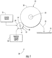
- FIG. 1 schematically illustrates imaging system or printer 20 according to an example embodiment.
- Printer 20 forms images upon a print medium 21 using an electrostatically charged imaging material, such as an imaging liquid or ink.
- printer 20 includes a developer roller 33 that transfers the electrostatically charged imaging liquid to an electrostatically charged imaging surface 24.
- the developer roller 33 has an outer layer having a composition that provides a desired level of electrical conductivity and reduces long-term damage to the imaging surface 24 or its performance over time.
- Printer 20 includes imaging member 22 having imaging surface 24, charge source 25, imaging liquid supply 30 and developer roller 33.
- Imaging member 22 comprises a member supporting imaging surface 24.
- Imaging surface 24 (sometimes referred to as an imaging plate) comprises a surface configured to have one or more electrostatic patterns or images formed thereon and to have electrostatically charged imaging material, such as imaging liquid, applied thereto.
- the imaging material adheres to selective portions of imaging surface 24 based upon the electrostatic images on surface 24 to form imaging material images on surface 24.
- the imaging material images are then subsequently transferred to a print medium 21 as indicated by arrow 35. Such transfer may be achieved using one of more belts, drums and the like.
- imaging member 22 comprises a drum configured be rotated about axis 23.
- imaging member 22 may comprise a belt or other supporting structures.
- surface 24 comprises a photoconductor or photoreceptor configured to be charged and have portions selectively discharged in response to optical radiation such that the charged and discharged areas form the electrostatic images.
- surface 24 may be either selectively charged or selectively discharged in other manners. For example, ionic beams or activation of individual pixels along surface 24 using transistors may be used to form electrostatic images on surface 24.
- imaging surface 24 comprises a photoconductive polymer.
- imaging surface 24 has an outermost layer with a composition of a polymer matrix including charge transfer molecules (also known as a photoacid).
- the matrix may comprise a polycarbonate matrix including a charge transfer molecule that in response to impingement by light, generates an electrostatic charge that is transferred to the surface.
- imaging surface 24 may comprise other photoconductive polymer compositions.
- Charge source 25 comprises a device configured to electrostatically charge developer roller 33 so as to electrostatically charge the imaging liquid applied to surface 24 by developer roller 33.
- Imaging liquid supply 30 comprises a device configured to supply imaging liquid to developer roller 33.
- imaging liquid supply 30 supplies a liquid toner.
- imaging liquid supply 30 supplies a liquid carrier and colorant particles (also known as toner particles).
- the liquid carrier comprises an ink carrier oil, such as Isopar, a low molecular weight hydrocarbon oil.
- the liquid carrier may include other additional components such as a high molecular weight oil, such as mineral oil, a lubricating oil and a defoamer.
- the liquid carrier and colorant particles comprises HEWLETT-PACKARD ELECTRO INK commercially available from Hewlett-Packard.
- the imaging liquid may comprise other imaging liquids.
- Developer roller 33 transfers and applies electrostatically charged imaging liquid to imaging surface 24.
- Developer roller 33 includes a shaft 37 and an exterior layer 39.
- Shaft 37 supports layer 39 for rotation about an axis 31.
- Exterior layer 39 extends about shaft 37 and formed an exterior of roller 33.
- Layer 39 has an exterior surface 42 upon which the electrostatically charged imaging liquid is carried as it is being transferred to imaging surface 24. Surface 42 is rotated into contact or at lease close proximity to imaging surface 24. During such transfer, any gap between surfaces 42 and 24 is filled with the electrostatically charged imaging liquid being transferred.
- layer 39 is illustrated as being in direct contact with shaft 37, in other embodiments, additional intermediate layers may be provided between shaft 37 and layer 39.
- Layer 39 is formed from materials or has a composition such that layer 39 has a desired level or range of electric conductivity so as to carry and transport like a statically charged imaging liquid to imaging surface 24.
- the composition of layer reduces long-term damage to the imaging surface 24 or its performance over time.
- imaging surface 24 comprises a photoconductive polymer, such as the example formulation provided above
- certain materials, such as certain salts, contained in existing developer rollers leech out from the developer roller over time and coat upon imaging surface 24, degrading its performance. It is further believed that such materials may further deteriorate a life of imaging surface 24.
- such salts that have been plated upon surface 24 are believed to diffuse the generated electrostatic charge on surface 24. This charge diffusion reduces the sharpness and resolution of the electrostatic image and the subsequently printed image.
- Layer 39 has a composition that avoids or reduces this issue.
- layer 39 is formed from one or more polymers, one or more electrical conductivity enhancers and one or more ionic salts that are soluble in a low molecular weight hydrocarbon oil.
- a "low molecular weight hydrocarbon oil” or a “low molecular weight oil” comprises an oil having a carbon count ranging from C 7 (90 grams/mole molar mass) to C 25 (326 grams/mole molar mass).
- layer 39 is formed from one or more polymers, one or more electrical conductivity enhancers and one or more ionic salts that are soluble in a low molecular weight hydrocarbon oil having a carbon count ranging from C 7 (90 grams/mole molar mass) to C 14 (198 grams/mole molar mass).
- the one or more electrical conductivity enhancers such as carbon black, provide the polymer composition with electrical conductivity.
- the one of more ionic salts also assist in providing the polymer composition of layer 39 with ionic electrical conductivity.
- the composition includes a mixture of carbon black and one or more ionic salts, a desired level of electrical conductivity (and a desired corresponding level of electrical bulk resistivity) is achieved with a reduced likelihood of "hot spots" which may otherwise be associated with compositions that solely rely upon carbon black for providing the desired level of electric conductivity.
- the carbon black allows the use of ionic salts which are less damaging to imaging surface 24 but which have a lower electrical conductivity as compared to other high electrical conductivity salts that are used in compositions that rely completely upon ionic salts for providing the electrical conductivity of layer 39.
- any of the ionic salts that leeches from layer 39 over time is largely dissolved in the liquid carrier or imaging oil of the imaging liquid being transferred to imaging surface 24.
- This liquid carrier largely comprised of low molecular weight imaging oil, simply carries the colorant particles and transfers the colorant particles to imaging surface 24.
- the imaging oil itself does not substantially accumulate on imaging service 24.
- the ionic salts dissolved in the liquid carrier flow through printer 20 with the liquid carrier.
- any contact between the leached ionic salts and imaging service 24 is largely temporary such that the ionic salts are not permitted to substantially coat imaging surface 24 and are not in contact with imaging surface 24 a sufficient period of time so as to substantially damage imaging surface 24.
- the composition of layer 39 provides a desired level of electrical conductivity and reduces long-term damage to the imaging surface 24 or its performance over time
- layer 39 is provided with an electrical bulk resistivity of between 1x10 5 and 1x10 7 ohm.cm
- the composition of layer 39 comprises a polyurethane mixed with a highly structured carbon-14 and a quarternary ammonium sulfate with an aliphatic hydrocarbon chain.
- layer 39 has the following composition:
- the composition of layer 39 is formed by reacting and isocyanate and an ester based polyol to form a polyurethane, a low hardness elastomer.
- the polyol Prior to this reaction, the polyol is high shear mixed with an ammonium sulfate alkyl chain salt (such as commercially available LAROSTAT 264A by BASF) and a highly structured carbon black (such as Ketjen Black EC600JD by AkzoNobel or Vulcan X72R by Cabot Corp.).
- an ammonium sulfate alkyl chain salt such as commercially available LAROSTAT 264A by BASF
- a highly structured carbon black such as Ketjen Black EC600JD by AkzoNobel or Vulcan X72R by Cabot Corp.
- the ratio of the polyol to isocyanate mixture results in a rubber material with a durometer of between 30 and 38 Shore A.
- ammonium sulfate alkyl chain salt (LAROSTAT 264A) is added between 1-3 parts per hundred parts (pphp) polyol and mixed with a carbon black of 0.1 to 0.8 pphp polyol.
- the particular salts and relative percentages of salts and carbon black may be adjusted so as to tune a bulk resistivity of layer 39 and of developer roller 33.
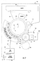
- FIG. 2 schematically illustrates printer 120, another embodiment of printer 20 shown in Figure 1 .
- printer 120 utilizes developer rollers 33.
- Printer 120 comprises a liquid electrophotographic (LEP) printer.
- Printer 120 (sometimes embodied as part of an offset color press) includes drum 122, photoconductor 124, charger 126, imager 128, ink carrier oil reservoir 130, ink supply 131, developer 132, internally and/or externally heated intermediate transfer member 134, heating system 136, impression member 138 and cleaning station 140.
- LEP liquid electrophotographic
- Drum 122 comprises a movable support structure supporting photoconductor 124.
- Drum 122 is configured to be rotationally driven about axis 123 in a direction indicated by arrow 125 by a motor and transmission (not shown).
- a motor and transmission not shown.
- distinct surface portions of photoconductor 124 are transported between stations of printer 120 including charger 126, imager 128, ink developers 132, transfer member 134 and charger 134.
- photoconductor 124 may be driven between substations in other manners.
- photoconductor 124 may be provided as part of an endless belt supported by a plurality of rollers.
- Photoconductor 124 also sometimes referred to as a photoreceptor, comprises a multi-layered structure configured to be charged and to have portions selectively discharged in response to optical radiation such that charged and discharged areas form a discharged image to which charged printing material is adhered.
- Charger 126 comprises a device configured to electrostatically charge surface 147 of photoconductor 124.
- charger 126 comprises a charge roller which is rotationally driven while in sufficient proximity to photoconductor 124 so as to transfer a negative static charge to surface 147 of photoconductor 124.
- charger 126 may alternatively comprise one or more corotrons or scorotrons.
- other devices for electrostatically charging surface 147 of photoconductor 124 may be employed.
- Imager 128 comprises a device configured to selectively electrostatically discharge surface 147 so as to form an image.
- imager 128 comprises a scanning laser which is moved across surface 147 as drum 122 and photoconductor 124 are rotated about axis 123. Those portions of surface 147 which are impinged by light or laser 150 are electrostatically discharged to form an image (or latent image) upon surface 147.
- imager 128 may alternatively comprise other devices configured to selectively emit or selectively allow light to impinge upon surface 147.
- imager 128 may alternatively include one or more shutter devices which employ liquid crystal materials to selectively block light and to selectively allow light to pass to surface 147.
- imager 128 may alternatively include shutters which include micro or nano light-blocking shutters which pivot, slide or otherwise physically move between a light blocking and light transmitting states.
- Ink carrier reservoir 130 comprises a container or chamber configured to hold ink carrier oil for use by one or more components of printer 120.
- ink carrier reservoir 130 is configured to hold ink carrier oil for use by cleaning station 140 and ink supply 131.
- ink carrier reservoir 130 serves as a cleaning station reservoir by supplying ink carrier oil to cleaning station 140 which applies the ink carrier oil against photoconductor 124 to clean the photoconductor 124.
- cleaning station 140 further cools the ink carrier oil and applies ink carrier oil to photoconductor 124 to cool surface 147 of photoconductor 124.
- cleaning station 140 may include a heat exchanger or cooling coils in ink care reservoir 130 to cool the ink carrier oil.
- the ink carrier oil supply to cleaning station 140 further assists in diluting concentrations of other materials such as particles recovered from photoconductor 124 during cleaning.
- ink carrier oil After ink carrier oil has been applied to surface 147 to clean and/or cool surface 147, the surface 147 is wiped with an absorbent roller and/or scraper.
- the removed carrier oil is returned to ink carrier reservoir 130 as indicated by arrow 153.
- the ink carrier oil returning to ink carrier reservoir 130 may pass through one or more filters 157 (schematically illustrated).
- filters 157 Schematically illustrated
- ink carrier oil in reservoir 130 is further supplied to ink supply 131.
- ink carrier reservoir 130 may alternatively operate independently of cleaning station 140, wherein ink carrier reservoir 130 just supplies ink carrier oil to ink supply 131.
- Ink supply 131 comprises a source of printing material for ink developers 132.
- Ink supply 131 receives ink carrier oil from carrier reservoir 130.
- the ink carrier oil supplied by ink carrier reservoir 130 may comprise new ink carrier oil supplied by a user, recycled ink carrier oil or a mixture of new and recycling carrier oil.
- Ink supply 131 mixes being carrier oil received from ink carrier reservoir 130 with pigments or other colorant particles. The mixture is applied to ink developers 132 as needed by ink developers 132 using one or more sensors and solenoid actuated valves (not shown).
- the raw, virgin or unused printing material may comprise a liquid or fluid ink comprising a liquid carrier and colorant particles.
- the colorant particles have a size of less than 2 ⁇ m. In different embodiments, the particle sizes may be different.
- the printing material generally includes approximately 3% by weight, colorant particles or solids part to being applied to surface 147.
- the colorant particles include a toner binder resin comprising hot melt adhesive.
- the liquid carrier comprises an ink carrier oil, such as Isopar, and one or more additional components such as a high molecular weight oil, such as mineral oil, a lubricating oil and a defoamer.
- the printing material including the liquid carrier and the colorant particles, comprises HEWLETT-PACKARD ELECTRO INK commercially available from Hewlett-Packard.
- Ink developers 132 comprises devices configured to apply printing material to surface 147 based upon the electrostatic charge upon surface 147 and to develop the image upon surface 147.
- ink developers 132 comprise binary ink developers (BIDs) circumferentially located about drum 122 and photoconductor 124. Such ink developers are configured to form a substantially uniform 6 ⁇ thick electrostatically charged film composed of approximately 20% solids which is transferred to surface 147.
- ink developers 132 may comprise other devices configured to transfer electrostatically charged liquid printing material or toner to surface 147.
- developers 132 may be configured to apply a dry electrostatically charged printing material, such as dry toner, to surface 147.
- each of ink developers 132 includes a developer roller 33.
- developer rollers 33 have an outer layer 39 (shown in Figure 1 ) that provides a desired level or range of electric conductivity/resistance so as to carry and transport electrostatically charged imaging liquid to imaging surface 24.
- the composition of layer 39 reduces long-term damage to the imaging surface provided by photoconductor 124 or its performance over time.
- Intermediate transfer member 134 comprises a member configured to transfer the printing material upon surface 147 to a print medium 152 (schematically shown).
- Intermediate transfer member 134 includes an exterior surface 154 which is resiliently compressible and which is also configured to be electrostatically charged. Because surface 154 is resiliently compressible, surface 154 conforms and adapts to irregularities in print medium 152. Because surface 154 is configured to be electrostatically charged, surface 154 may be charged so as to facilitate transfer of printing material from surface 147 to surface 154.
- intermediate transfer member 134 may include a drum 156 and an external blanket 158. Drum 156 supports blanket 158 which provides intermediate transfer member 134 with surface 154.
- intermediate transfer member 134 may have other configurations.
- intermediate transfer member 134 may alternatively comprise an endless belt supported by a plurality of rollers in contact with or in close proximity to surface 147.
- Heating system 136 comprises one or more devices configured to apply heat to printing material being carried by surface 154 from photoconductor 124 to medium 152.
- heating system 136 includes internal heater 160, external heater 162 and vapor collection plenum 163.
- Internal heater 160 comprises a heating device located within drum 156 that is configured to emit heat or inductively generate heat which is transmitted to surface 154 to heat and dry the printing material carried at surface 154.
- External heater 162 comprises one or more heating units located about transfer member 134. According to one embodiment, heaters 160 and 162 may comprise infrared heaters.
- Heaters 160 and 162 are configured to heat printing material to a temperature of at least 85°C and less than or equal to about 110°C. In still other embodiments, heaters 160 and 162 may have other configurations and may heat printing material upon transfer member 134 to other temperatures. In particular embodiments, heating system 136 may alternatively include one of either internal heater 160 or external heater 162.
- Vapor collection plenum 163 comprises a housing, chamber, duct, vent, plenum or other structure at least partially circumscribing intermediate transfer member 134 so as to collect or direct ink or printing material vapors resulting from the heating of the printing material on transfer member 134 to a condenser (not shown).
- Impression member 138 comprises a cylinder adjacent to intermediate transfer member 134 so as to form a nip 164 between member 134 and member 138.
- Medium 152 is generally fed between transfer member 134 and impression member 138, wherein the printing material is transferred from transfer member 134 to medium 152 at nip 164.
- impression member 138 is illustrated as a cylinder or roller, impression member 138 and alternatively comprise an endless belt or a stationary surface against which intermediate transfer member 134 moves.
- Cleaning station 140 comprises one or more devices configured to remove any residual printing material from photoconductor 124 prior to surface areas of photoconductor 124 being once again charged at charger 126.
- cleaning station 140 may comprise one or more devices configured to apply a cleaning fluid to surface 147, wherein residual toner particles are removed by one or more is absorbent rollers.
- cleaning station 140 may additionally include one or more scraper blades.
- other devices may be utilized to remove residual toner and electrostatic charge from surface 147.
- ink developers 132 develop an image upon surface 147 by applying electrostatically charged ink having a negative charge.
- charge eraser 135, comprising one or more light emitting diodes, discharges any remaining electrical charge upon such portions of surface 147 and ink image is transferred to surface 154 of intermediate transfer member 34.
- the printing material formed comprises and approximately 1.0 ⁇ thick layer of approximately 90% solids color or particles upon intermediate transfer member 134.
- Heating system 136 applies heat to such printing material upon surface 154 so as to evaporate the carrier liquid of the printing material and to melt toner binder resin of the color and particles or solids of the printing material to form a hot melt adhesive. Thereafter, the layer of hot colorant particles forming an image upon surface 154 is transferred to medium 152 passing between transfer member 134 and impression member 138. In the embodiment shown, the hot colorant particles are transferred to print medium 152 at approximately 90°C. The layer of hot colorant particles cool upon contacting medium 152 on contact in nip 164.
- multi--shot in lieu of creating one color separation at a time on a surface 154, sometimes referred to as "multi--shot" process, the above process may be modified to employ a one-shot color process in which all color separations are layered upon surface 154 of intermediate transfer member 134 prior to being transferred to and deposited upon medium 152.
- FIG 3 illustrates an example ink developer unit 220 of ink developers 132 of printer 120 shown in Figure 2 .
- unit 220 includes developer roller 33.
- Unit 220 additionally includes reservoir 253, toner chamber 255, main electrodes 256, back electrode 257, squeegee roller 260, developer cleaner 262, developer cleaner wiper 264, sponge roller 266 and squeezer roller 268.
- Reservoir 253 receives excess imaging liquid or ink returning from developer roller 42 as removed by squeegee roller 260.
- Reservoir 253 may have a variety of different sizes, shapes and configurations.
- Toner chamber turned 55 comprises a cavity having an inlet (not shown) through which imaging liquid is supplied from reservoir to learn 53 to chamber turned 55 and two between the electrode 256 and developer roller 33.
- Main electrodes 256 and back electrode 257 comprise members situated opposite to developer roller 33 and configured to be electrically charged.
- back electrode 257 has a dielectric tip opposite roller 33 and cooperates with electrode 256 to form toner chamber 255.
- Squeegee roller 260 removes excess imaging liquid from the surface of roller 33.
- squeegee roller 260 may be selectively charged to control the thickness or concentration of imaging liquid upon the surface 42 of roller 33.
- electrode 256 and squeegee roller 260 are appropriately charged so as to form a substantially uniform 6 ⁇ thick film composed of approximately 20% solids on the surface 42 of roller 33 which is especially transferred to the imaging service provided by photoconductor 124 (shown in Figure 2 ).
- Developer cleaner 262 developer cleaner wiper 264, sponge roller 266 and squeezer roller 268 form a developer roller cleaning system for removing imaging liquid from roller 33 which has not been transferred to the imaging surface.
- Developer cleaner 262 comprises a roller having a surface charged so as to attract and remove imaging liquid from the surface 42 of roller 33. In one particular embodiment which roller 33 has a charge of approximately -450 volts, cleaner 262 has a charge of approximately -250 volts. Developer cleaner 262 is located in close proximity to developer roller 33 near an upper portion of chamber 255. As a result, imaging liquid removed by cleaner 262 may flow towards outlet port 270 with assistance of gravity.
- cleaner 262 is configured to be rotatably driven about axis 274 while in engagement with wiper 264.
- cleaner 262 is illustrated as a roller, cleaner 262 may alternatively comprise a belt.
- Wiper 264 comprises a scraper blade supported in close proximity or in contact with a surface of cleaner 262.
- cleaner 262 rotates in a direction indicated by arrow 276 against wiper 264 such that printing material or imaging liquid is removed from the surface of cleaner 262.
- Sponge roller 266 cleans cleaner 262 and wiper 264.
- Sponge roller 266 comprises a rotationally driven roller having an absorbent outer sponge surface in contact with or in close proximity to one or both of cleaner 262 and wiper 264.
- Squeezer roller 268 comprises a rotationally driven roller having a relatively incompressible rigid outer surface in contact with sponge roller 266. Squeeze a roller 268 squeezes imaging liquid from sponge roller 266.
- each developer unit 220 may have different configurations. For example, in other embodiments, each developer unit 220 may have different systems or mechanisms for cleaning developer roller 33.
Landscapes
- Physics & Mathematics (AREA)
- General Physics & Mathematics (AREA)
- Wet Developing In Electrophotography (AREA)
- Electrostatic Charge, Transfer And Separation In Electrography (AREA)
- Ink Jet (AREA)
Claims (15)
- Druckervorrichtung (20), die folgende Merkmale umfasst:
eine Entwicklerwalze (33), die Folgendes umfasst:eine Welle (37);eine Schicht (39) um die Welle (37) herum, wobei die Schicht (39) eine Außenseite der Walze (33) bildet und Folgendes umfasst:ein oder mehrere Polymere;Kohleschwarz; undein ionisches Salz, das in einem Kohlenwasserstofföl mit niedrigem Molekulargewicht löslich ist, wobei ein Kohlenwasserstofföl mit niedrigem Molekulargewicht ein Öl mit einer Kohlenstoffzahl im Bereich von C7 (Molmasse von 90 g/mol) bis C25 (Molmasse von 326 g/mol) umfasst. - Vorrichtung nach Anspruch 1, wobei das eine oder die mehreren Polymere Polyurethan enthalten.
- Vorrichtung nach Anspruch 1, wobei das ionische Salz ein quartäres Ammoniumsulfat mit einer aliphatischen Kohlenwasserstoffkette umfasst.
- Vorrichtung nach Anspruch 1, wobei das ionische Salz eine aliphatische Kohlenwasserstoffkette enthält.
- Vorrichtung nach Anspruch 1, wobei die Schicht (39) einen spezifischen Volumenwiderstand zwischen 1 x 10⁵ Ohm·cm und 1 x 10⁷ Ohm·cm aufweist.
- Vorrichtung nach Anspruch 1, die ferner eine Trommel (22, 122) mit einer äußeren fotoleitfähigen Polymerschicht (24, 124) gegenüber der Walze (33) umfasst.
- Vorrichtung nach Anspruch 6, die ferner eine Quelle von Kohlenwasserstofföl mit niedrigem Molekulargewicht mit darin suspendierten Tonerpartikel umfasst, wobei die Quelle derart konfiguriert ist, dass das Kohlenwasserstofföl mit niedrigem Molekulargewicht auf der Schicht (39) der Walze (33) aufgetragen wird, und wobei die Walze (33) das Kohlenwasserstofföl mit niedrigem Molekulargewicht auf die photoleitfähige Polymerschicht (24, 124) der Trommel (22, 122) überträgt.
- Vorrichtung nach Anspruch 7, die ferner eine zweite Walze (33) gegenüber der äußeren photoleitfähigen Polymerschicht der Trommel (22, 122) umfasst, wobei die zweite Walze (33) Folgendes umfasst:eine zweite Welle (37);eine zweite Schicht (39) um die Welle (37) herum, wobei die zweite Schicht (39) eine Außenseite der zweiten Walze (33) bildet und Folgendes umfasst:ein oder mehrere Polymere;Kohleschwarz; undein ionisches Salz, das in einem Kohlenwasserstofföl mit niedrigem Molekulargewicht löslich ist.
- Vorrichtung nach Anspruch 1, wobei das eine oder die mehreren Polymere Polyurethan enthalten, wobei das ionische Salz eine aliphatische Kohlenwasserstoffkette enthält und wobei die Schicht (39) einen spezifischen Volumenwiderstand zwischen 1 x 10⁵ Ohm·cm und 1 x 10⁷ Ohm·cm aufweist.
- Verfahren, umfassend:
Übertragen eines Kohlenwasserstoff-Bilderzeugungsöls mit niedrigem Molekulargewicht auf eine photoleitfähige Polymerschicht auf einer Photoleitertrommel (22, 122) mit einem Entwickler (33) mit einer äußeren Schicht (39), umfassend:eines oder mehrere Polymere;Kohleschwarz; undein ionisches Salz, das in einem Kohlenwasserstofföl mit niedrigem Molekulargewicht löslich ist, wobei ein Kohlenwasserstofföl mit niedrigem Molekulargewicht ein Öl mit einer Kohlenstoffzahl im Bereich von C7 (Molmasse von 90 g/mol) bis C25 (Molmasse von 326 g/mol) umfasst. - Verfahren nach Anspruch 10, wobei das eine oder die mehreren Polymere Polyurethan enthalten.
- Verfahren nach Anspruch 10, wobei das ionische Salz ein quartäres Ammoniumsulfat mit einer aliphatischen Kohlenwasserstoffkette umfasst.
- Verfahren nach Anspruch 10, wobei das ionische Salz eine aliphatische Kohlenwasserstoffkette enthält.
- Verfahren nach Anspruch 10, bei der die Schicht (39) einen spezifischen Volumenwiderstand zwischen 1 x 10⁵ Ohm·cm und 1 x 10⁷ Ohm·cm aufweist.
- Verfahren nach Anspruch 10, wobei das eine oder die mehreren Polymere Polyurethan enthalten, wobei das ionische Salz eine aliphatische Kohlenwasserstoffkette enthält und wobei die Schicht (39) einen spezifischen Volumenwiderstand zwischen 1 x 10⁵ Ohm·cm und 1 x 10⁷ Ohm·cm aufweist.
Applications Claiming Priority (1)
| Application Number | Priority Date | Filing Date | Title |
|---|---|---|---|
| PCT/US2008/078512 WO2010039134A1 (en) | 2008-10-01 | 2008-10-01 | Roller |
Publications (3)
| Publication Number | Publication Date |
|---|---|
| EP2332015A1 EP2332015A1 (de) | 2011-06-15 |
| EP2332015A4 EP2332015A4 (de) | 2015-06-24 |
| EP2332015B1 true EP2332015B1 (de) | 2019-05-22 |
Family
ID=42073744
Family Applications (1)
| Application Number | Title | Priority Date | Filing Date |
|---|---|---|---|
| EP08877201.7A Not-in-force EP2332015B1 (de) | 2008-10-01 | 2008-10-01 | Druckervorrichtung mit einer entwicklungswalze |
Country Status (3)
| Country | Link |
|---|---|
| US (1) | US8594535B2 (de) |
| EP (1) | EP2332015B1 (de) |
| WO (1) | WO2010039134A1 (de) |
Families Citing this family (11)
| Publication number | Priority date | Publication date | Assignee | Title |
|---|---|---|---|---|
| WO2011096929A1 (en) * | 2010-02-05 | 2011-08-11 | Hewlett-Packard Development Company, L.P. | Imaging system and method |
| US9639627B2 (en) | 2010-07-26 | 2017-05-02 | Hewlett-Packard Development Company, L.P. | Method to search a task-based web interaction |
| WO2012148428A1 (en) | 2011-04-29 | 2012-11-01 | Hewlett-Packard Development Company, L.P. | Apparatus, printers, and methods to remove material from a printer surface |
| US9539822B2 (en) * | 2012-01-13 | 2017-01-10 | Hewlett-Packard Development Company, L.P. | Digital printers |
| EP2820485B1 (de) | 2012-03-01 | 2016-05-11 | Hewlett-Packard Development Company, L.P. | Aufladerolle |
| WO2013130084A1 (en) * | 2012-03-01 | 2013-09-06 | Hewlett-Packard Development Company, L.P. | Charge roller |
| JP6614807B2 (ja) * | 2015-05-28 | 2019-12-04 | キヤノン株式会社 | 画像形成装置 |
| EP3341798B1 (de) | 2016-01-27 | 2019-08-21 | Hewlett-Packard Development Company, L.P. | Elektrofotografische flüssigtintenentwicklereinheit |
| CN108604076B (zh) | 2016-01-27 | 2021-02-12 | 惠普发展公司,有限责任合伙企业 | 液体电子照相墨水显影单元 |
| EP3341797A4 (de) * | 2016-01-27 | 2018-07-04 | Hewlett-Packard Development Company, L.P. | Elektrisch leitende walze |
| WO2018133946A1 (en) | 2017-01-20 | 2018-07-26 | Hp Indigo B.V. | Developer roller for liquid electrophotographic printing |
Family Cites Families (15)
| Publication number | Priority date | Publication date | Assignee | Title |
|---|---|---|---|---|
| GB2041790B (en) * | 1979-02-23 | 1983-07-27 | Savin Corp | Liquid development of electrostatic images |
| US5481341A (en) * | 1993-08-18 | 1996-01-02 | Xerox Corporation | Roller for controlling application of carrier liquid |
| EP0684613A3 (de) * | 1994-05-27 | 1996-06-26 | Bridgestone Corp | Halbleitfähiges Polymerelement, Verfahren zur Herstelllung desselben und Vorrichtung damit. |
| US6117557A (en) * | 1995-04-19 | 2000-09-12 | Lexmark International, Inc. | Caprolactone ester polyurethane developer roller |
| EP0869404B1 (de) * | 1997-03-31 | 2000-07-12 | Canon Kabushiki Kaisha | Mit einer Harzschicht überzogenes Entwicklerträgerelement, dessen Bindemittelharz von Molekulargewicht 3000 bis 50000 ein Copolymer enthält mit einem Methyl Methacrylat Monomer und einem Stickstoff enthaltenden Vinylmonomer |
| US6067434A (en) * | 1997-06-27 | 2000-05-23 | Bridgestone Corporation | Developing roller and developing apparatus |
| US6397032B1 (en) * | 1999-09-10 | 2002-05-28 | Canon Kabushiki Kaisha | Image forming apparatus including a developer bearing member having multiple layers |
| US6673499B2 (en) * | 2000-10-26 | 2004-01-06 | Samsung Electronics Co., Ltd. | Organophotoreceptor having an improved ground stripe |
| JP2004287085A (ja) * | 2003-03-20 | 2004-10-14 | Fuji Xerox Co Ltd | 画像形成装置 |
| CN100437374C (zh) * | 2003-10-09 | 2008-11-26 | 富士电机电子技术株式会社 | 电子照相显影滚筒及使用该滚筒的成像设备 |
| US6970672B2 (en) * | 2004-03-25 | 2005-11-29 | Lexmark International, Inc. | Electrophotographic toner regulating member with polymer coating having surface roughness modified by fine particles |
| US20060020100A1 (en) * | 2004-07-20 | 2006-01-26 | Shirley Lee | Conductive agents for polyurethane |
| US7406277B2 (en) * | 2005-05-31 | 2008-07-29 | Sumitomo Rubber Industries, Ltd. | Semiconductive rubber member |
| KR100648930B1 (ko) * | 2005-09-16 | 2006-11-27 | 삼성전자주식회사 | 화상형성장치용 도전성 전사롤러 |
| US7981586B2 (en) * | 2006-09-19 | 2011-07-19 | Konica Minolta Business Technologies, Inc. | Image forming method using the same |
-
2008
- 2008-10-01 US US13/119,959 patent/US8594535B2/en active Active
- 2008-10-01 EP EP08877201.7A patent/EP2332015B1/de not_active Not-in-force
- 2008-10-01 WO PCT/US2008/078512 patent/WO2010039134A1/en not_active Ceased
Non-Patent Citations (1)
| Title |
|---|
| None * |
Also Published As
| Publication number | Publication date |
|---|---|
| EP2332015A1 (de) | 2011-06-15 |
| WO2010039134A1 (en) | 2010-04-08 |
| EP2332015A4 (de) | 2015-06-24 |
| US8594535B2 (en) | 2013-11-26 |
| US20110170909A1 (en) | 2011-07-14 |
Similar Documents
| Publication | Publication Date | Title |
|---|---|---|
| EP2332015B1 (de) | Druckervorrichtung mit einer entwicklungswalze | |
| US8041275B2 (en) | Release layer | |
| CN100559299C (zh) | 图像形成装置 | |
| EP1574915B1 (de) | Gerät zur Reinigung einer Bildübertragungsvorrichtung | |
| CN102692844A (zh) | 显影辊 | |
| US9176432B2 (en) | Imaging system and method | |
| EP2467757B1 (de) | Zwischentransferelementstuch, vorrichtung und transferverfahren | |
| EP2670597B1 (de) | Drucker sowie verfahren und vorrichtung zur erzeugung eines bildes auf einem druckträger | |
| WO2005094470A2 (en) | Electrophotographic toner regulating member with polymer coating having surface roughness modified by fine particles | |
| JP5054136B2 (ja) | 中間転写ブランケット及び電子写真印刷用中間転写体 | |
| EP2510403B1 (de) | Abbildungssystem und -verfahren | |
| US20190377275A1 (en) | Method and apparatus for reducing contamination in liquid electrophotographic printing | |
| EP3769158B1 (de) | Reinigungsflächen für druckvorrichtung | |
| WO2017178043A1 (en) | Cleaning unit | |
| US20240419104A1 (en) | Servicing print blankets | |
| US11906925B2 (en) | Cleaner rollers and cleaning electrophotographic photoconductors | |
| JP5203527B2 (ja) | 印刷部及び電子写真印刷装置 |
Legal Events
| Date | Code | Title | Description |
|---|---|---|---|
| PUAI | Public reference made under article 153(3) epc to a published international application that has entered the european phase |
Free format text: ORIGINAL CODE: 0009012 |
|
| 17P | Request for examination filed |
Effective date: 20110331 |
|
| AK | Designated contracting states |
Kind code of ref document: A1 Designated state(s): AT BE BG CH CY CZ DE DK EE ES FI FR GB GR HR HU IE IS IT LI LT LU LV MC MT NL NO PL PT RO SE SI SK TR |
|
| AX | Request for extension of the european patent |
Extension state: AL BA MK RS |
|
| DAX | Request for extension of the european patent (deleted) | ||
| RA4 | Supplementary search report drawn up and despatched (corrected) |
Effective date: 20150526 |
|
| RIC1 | Information provided on ipc code assigned before grant |
Ipc: G03G 15/08 20060101ALI20150519BHEP Ipc: B41J 17/02 20060101ALI20150519BHEP Ipc: G03G 15/10 20060101AFI20150519BHEP |
|
| GRAP | Despatch of communication of intention to grant a patent |
Free format text: ORIGINAL CODE: EPIDOSNIGR1 |
|
| STAA | Information on the status of an ep patent application or granted ep patent |
Free format text: STATUS: GRANT OF PATENT IS INTENDED |
|
| INTG | Intention to grant announced |
Effective date: 20190301 |
|
| INTG | Intention to grant announced |
Effective date: 20190301 |
|
| GRAS | Grant fee paid |
Free format text: ORIGINAL CODE: EPIDOSNIGR3 |
|
| GRAA | (expected) grant |
Free format text: ORIGINAL CODE: 0009210 |
|
| STAA | Information on the status of an ep patent application or granted ep patent |
Free format text: STATUS: THE PATENT HAS BEEN GRANTED |
|
| RAP1 | Party data changed (applicant data changed or rights of an application transferred) |
Owner name: HEWLETT-PACKARD DEVELOPMENT COMPANY, L.P. |
|
| AK | Designated contracting states |
Kind code of ref document: B1 Designated state(s): AT BE BG CH CY CZ DE DK EE ES FI FR GB GR HR HU IE IS IT LI LT LU LV MC MT NL NO PL PT RO SE SI SK TR |
|
| REG | Reference to a national code |
Ref country code: GB Ref legal event code: FG4D |
|
| REG | Reference to a national code |
Ref country code: CH Ref legal event code: EP |
|
| REG | Reference to a national code |
Ref country code: IE Ref legal event code: FG4D |
|
| REG | Reference to a national code |
Ref country code: DE Ref legal event code: R096 Ref document number: 602008060209 Country of ref document: DE |
|
| REG | Reference to a national code |
Ref country code: AT Ref legal event code: REF Ref document number: 1136847 Country of ref document: AT Kind code of ref document: T Effective date: 20190615 |
|
| REG | Reference to a national code |
Ref country code: NL Ref legal event code: MP Effective date: 20190522 |
|
| REG | Reference to a national code |
Ref country code: LT Ref legal event code: MG4D |
|
| PG25 | Lapsed in a contracting state [announced via postgrant information from national office to epo] |
Ref country code: PT Free format text: LAPSE BECAUSE OF FAILURE TO SUBMIT A TRANSLATION OF THE DESCRIPTION OR TO PAY THE FEE WITHIN THE PRESCRIBED TIME-LIMIT Effective date: 20190922 Ref country code: ES Free format text: LAPSE BECAUSE OF FAILURE TO SUBMIT A TRANSLATION OF THE DESCRIPTION OR TO PAY THE FEE WITHIN THE PRESCRIBED TIME-LIMIT Effective date: 20190522 Ref country code: HR Free format text: LAPSE BECAUSE OF FAILURE TO SUBMIT A TRANSLATION OF THE DESCRIPTION OR TO PAY THE FEE WITHIN THE PRESCRIBED TIME-LIMIT Effective date: 20190522 Ref country code: SE Free format text: LAPSE BECAUSE OF FAILURE TO SUBMIT A TRANSLATION OF THE DESCRIPTION OR TO PAY THE FEE WITHIN THE PRESCRIBED TIME-LIMIT Effective date: 20190522 Ref country code: NO Free format text: LAPSE BECAUSE OF FAILURE TO SUBMIT A TRANSLATION OF THE DESCRIPTION OR TO PAY THE FEE WITHIN THE PRESCRIBED TIME-LIMIT Effective date: 20190822 Ref country code: FI Free format text: LAPSE BECAUSE OF FAILURE TO SUBMIT A TRANSLATION OF THE DESCRIPTION OR TO PAY THE FEE WITHIN THE PRESCRIBED TIME-LIMIT Effective date: 20190522 Ref country code: NL Free format text: LAPSE BECAUSE OF FAILURE TO SUBMIT A TRANSLATION OF THE DESCRIPTION OR TO PAY THE FEE WITHIN THE PRESCRIBED TIME-LIMIT Effective date: 20190522 Ref country code: LT Free format text: LAPSE BECAUSE OF FAILURE TO SUBMIT A TRANSLATION OF THE DESCRIPTION OR TO PAY THE FEE WITHIN THE PRESCRIBED TIME-LIMIT Effective date: 20190522 |
|
| PG25 | Lapsed in a contracting state [announced via postgrant information from national office to epo] |
Ref country code: LV Free format text: LAPSE BECAUSE OF FAILURE TO SUBMIT A TRANSLATION OF THE DESCRIPTION OR TO PAY THE FEE WITHIN THE PRESCRIBED TIME-LIMIT Effective date: 20190522 Ref country code: BG Free format text: LAPSE BECAUSE OF FAILURE TO SUBMIT A TRANSLATION OF THE DESCRIPTION OR TO PAY THE FEE WITHIN THE PRESCRIBED TIME-LIMIT Effective date: 20190822 Ref country code: GR Free format text: LAPSE BECAUSE OF FAILURE TO SUBMIT A TRANSLATION OF THE DESCRIPTION OR TO PAY THE FEE WITHIN THE PRESCRIBED TIME-LIMIT Effective date: 20190823 |
|
| REG | Reference to a national code |
Ref country code: AT Ref legal event code: MK05 Ref document number: 1136847 Country of ref document: AT Kind code of ref document: T Effective date: 20190522 |
|
| PG25 | Lapsed in a contracting state [announced via postgrant information from national office to epo] |
Ref country code: AT Free format text: LAPSE BECAUSE OF FAILURE TO SUBMIT A TRANSLATION OF THE DESCRIPTION OR TO PAY THE FEE WITHIN THE PRESCRIBED TIME-LIMIT Effective date: 20190522 Ref country code: EE Free format text: LAPSE BECAUSE OF FAILURE TO SUBMIT A TRANSLATION OF THE DESCRIPTION OR TO PAY THE FEE WITHIN THE PRESCRIBED TIME-LIMIT Effective date: 20190522 Ref country code: DK Free format text: LAPSE BECAUSE OF FAILURE TO SUBMIT A TRANSLATION OF THE DESCRIPTION OR TO PAY THE FEE WITHIN THE PRESCRIBED TIME-LIMIT Effective date: 20190522 Ref country code: RO Free format text: LAPSE BECAUSE OF FAILURE TO SUBMIT A TRANSLATION OF THE DESCRIPTION OR TO PAY THE FEE WITHIN THE PRESCRIBED TIME-LIMIT Effective date: 20190522 Ref country code: SK Free format text: LAPSE BECAUSE OF FAILURE TO SUBMIT A TRANSLATION OF THE DESCRIPTION OR TO PAY THE FEE WITHIN THE PRESCRIBED TIME-LIMIT Effective date: 20190522 Ref country code: CZ Free format text: LAPSE BECAUSE OF FAILURE TO SUBMIT A TRANSLATION OF THE DESCRIPTION OR TO PAY THE FEE WITHIN THE PRESCRIBED TIME-LIMIT Effective date: 20190522 |
|
| REG | Reference to a national code |
Ref country code: DE Ref legal event code: R097 Ref document number: 602008060209 Country of ref document: DE |
|
| PG25 | Lapsed in a contracting state [announced via postgrant information from national office to epo] |
Ref country code: IT Free format text: LAPSE BECAUSE OF FAILURE TO SUBMIT A TRANSLATION OF THE DESCRIPTION OR TO PAY THE FEE WITHIN THE PRESCRIBED TIME-LIMIT Effective date: 20190522 |
|
| PLBE | No opposition filed within time limit |
Free format text: ORIGINAL CODE: 0009261 |
|
| STAA | Information on the status of an ep patent application or granted ep patent |
Free format text: STATUS: NO OPPOSITION FILED WITHIN TIME LIMIT |
|
| PG25 | Lapsed in a contracting state [announced via postgrant information from national office to epo] |
Ref country code: TR Free format text: LAPSE BECAUSE OF FAILURE TO SUBMIT A TRANSLATION OF THE DESCRIPTION OR TO PAY THE FEE WITHIN THE PRESCRIBED TIME-LIMIT Effective date: 20190522 |
|
| 26N | No opposition filed |
Effective date: 20200225 |
|
| PG25 | Lapsed in a contracting state [announced via postgrant information from national office to epo] |
Ref country code: PL Free format text: LAPSE BECAUSE OF FAILURE TO SUBMIT A TRANSLATION OF THE DESCRIPTION OR TO PAY THE FEE WITHIN THE PRESCRIBED TIME-LIMIT Effective date: 20190522 |
|
| PG25 | Lapsed in a contracting state [announced via postgrant information from national office to epo] |
Ref country code: MC Free format text: LAPSE BECAUSE OF FAILURE TO SUBMIT A TRANSLATION OF THE DESCRIPTION OR TO PAY THE FEE WITHIN THE PRESCRIBED TIME-LIMIT Effective date: 20190522 Ref country code: SI Free format text: LAPSE BECAUSE OF FAILURE TO SUBMIT A TRANSLATION OF THE DESCRIPTION OR TO PAY THE FEE WITHIN THE PRESCRIBED TIME-LIMIT Effective date: 20190522 |
|
| REG | Reference to a national code |
Ref country code: CH Ref legal event code: PL |
|
| PG25 | Lapsed in a contracting state [announced via postgrant information from national office to epo] |
Ref country code: CH Free format text: LAPSE BECAUSE OF NON-PAYMENT OF DUE FEES Effective date: 20191031 Ref country code: LI Free format text: LAPSE BECAUSE OF NON-PAYMENT OF DUE FEES Effective date: 20191031 Ref country code: LU Free format text: LAPSE BECAUSE OF NON-PAYMENT OF DUE FEES Effective date: 20191001 |
|
| REG | Reference to a national code |
Ref country code: BE Ref legal event code: MM Effective date: 20191031 |
|
| PG25 | Lapsed in a contracting state [announced via postgrant information from national office to epo] |
Ref country code: BE Free format text: LAPSE BECAUSE OF NON-PAYMENT OF DUE FEES Effective date: 20191031 |
|
| PG25 | Lapsed in a contracting state [announced via postgrant information from national office to epo] |
Ref country code: IE Free format text: LAPSE BECAUSE OF NON-PAYMENT OF DUE FEES Effective date: 20191001 |
|
| PGFP | Annual fee paid to national office [announced via postgrant information from national office to epo] |
Ref country code: FR Payment date: 20200917 Year of fee payment: 13 Ref country code: GB Payment date: 20200921 Year of fee payment: 13 |
|
| PG25 | Lapsed in a contracting state [announced via postgrant information from national office to epo] |
Ref country code: CY Free format text: LAPSE BECAUSE OF FAILURE TO SUBMIT A TRANSLATION OF THE DESCRIPTION OR TO PAY THE FEE WITHIN THE PRESCRIBED TIME-LIMIT Effective date: 20190522 |
|
| PG25 | Lapsed in a contracting state [announced via postgrant information from national office to epo] |
Ref country code: IS Free format text: LAPSE BECAUSE OF FAILURE TO SUBMIT A TRANSLATION OF THE DESCRIPTION OR TO PAY THE FEE WITHIN THE PRESCRIBED TIME-LIMIT Effective date: 20190922 |
|
| PG25 | Lapsed in a contracting state [announced via postgrant information from national office to epo] |
Ref country code: MT Free format text: LAPSE BECAUSE OF FAILURE TO SUBMIT A TRANSLATION OF THE DESCRIPTION OR TO PAY THE FEE WITHIN THE PRESCRIBED TIME-LIMIT Effective date: 20190522 Ref country code: HU Free format text: LAPSE BECAUSE OF FAILURE TO SUBMIT A TRANSLATION OF THE DESCRIPTION OR TO PAY THE FEE WITHIN THE PRESCRIBED TIME-LIMIT; INVALID AB INITIO Effective date: 20081001 |
|
| PGFP | Annual fee paid to national office [announced via postgrant information from national office to epo] |
Ref country code: DE Payment date: 20210921 Year of fee payment: 14 |
|
| GBPC | Gb: european patent ceased through non-payment of renewal fee |
Effective date: 20211001 |
|
| PG25 | Lapsed in a contracting state [announced via postgrant information from national office to epo] |
Ref country code: GB Free format text: LAPSE BECAUSE OF NON-PAYMENT OF DUE FEES Effective date: 20211001 |
|
| PG25 | Lapsed in a contracting state [announced via postgrant information from national office to epo] |
Ref country code: FR Free format text: LAPSE BECAUSE OF NON-PAYMENT OF DUE FEES Effective date: 20211031 |
|
| REG | Reference to a national code |
Ref country code: DE Ref legal event code: R119 Ref document number: 602008060209 Country of ref document: DE |
|
| PG25 | Lapsed in a contracting state [announced via postgrant information from national office to epo] |
Ref country code: DE Free format text: LAPSE BECAUSE OF NON-PAYMENT OF DUE FEES Effective date: 20230503 |