EP2330673A2 - Struktur zum Bilden eines Festoxidbrennstoffzellenstapels - Google Patents
Struktur zum Bilden eines Festoxidbrennstoffzellenstapels Download PDFInfo
- Publication number
- EP2330673A2 EP2330673A2 EP10191727A EP10191727A EP2330673A2 EP 2330673 A2 EP2330673 A2 EP 2330673A2 EP 10191727 A EP10191727 A EP 10191727A EP 10191727 A EP10191727 A EP 10191727A EP 2330673 A2 EP2330673 A2 EP 2330673A2
- Authority
- EP
- European Patent Office
- Prior art keywords
- fuel cell
- stack
- solid oxide
- oxide fuel
- accordance
- Prior art date
- Legal status (The legal status is an assumption and is not a legal conclusion. Google has not performed a legal analysis and makes no representation as to the accuracy of the status listed.)
- Withdrawn
Links
- 239000000446 fuel Substances 0.000 title claims abstract description 81
- 239000007787 solid Substances 0.000 title claims abstract description 32
- 238000009826 distribution Methods 0.000 claims abstract description 20
- 239000011521 glass Substances 0.000 claims abstract description 15
- 238000012360 testing method Methods 0.000 claims abstract description 7
- 238000004891 communication Methods 0.000 claims description 3
- 238000012544 monitoring process Methods 0.000 claims description 3
- 238000005245 sintering Methods 0.000 abstract description 11
- 239000007789 gas Substances 0.000 description 9
- 238000000034 method Methods 0.000 description 6
- 229910052751 metal Inorganic materials 0.000 description 4
- 239000002184 metal Substances 0.000 description 4
- 239000002737 fuel gas Substances 0.000 description 3
- 238000004519 manufacturing process Methods 0.000 description 3
- 238000005259 measurement Methods 0.000 description 3
- 229910001092 metal group alloy Inorganic materials 0.000 description 3
- 239000004215 Carbon black (E152) Substances 0.000 description 2
- CURLTUGMZLYLDI-UHFFFAOYSA-N Carbon dioxide Chemical compound O=C=O CURLTUGMZLYLDI-UHFFFAOYSA-N 0.000 description 2
- UGFAIRIUMAVXCW-UHFFFAOYSA-N Carbon monoxide Chemical compound [O+]#[C-] UGFAIRIUMAVXCW-UHFFFAOYSA-N 0.000 description 2
- UFHFLCQGNIYNRP-UHFFFAOYSA-N Hydrogen Chemical compound [H][H] UFHFLCQGNIYNRP-UHFFFAOYSA-N 0.000 description 2
- 238000005452 bending Methods 0.000 description 2
- 229910002091 carbon monoxide Inorganic materials 0.000 description 2
- 239000000919 ceramic Substances 0.000 description 2
- 230000005611 electricity Effects 0.000 description 2
- 239000003792 electrolyte Substances 0.000 description 2
- 229930195733 hydrocarbon Natural products 0.000 description 2
- 150000002430 hydrocarbons Chemical class 0.000 description 2
- 230000007774 longterm Effects 0.000 description 2
- 230000013011 mating Effects 0.000 description 2
- 230000001590 oxidative effect Effects 0.000 description 2
- 239000001301 oxygen Substances 0.000 description 2
- 229910052760 oxygen Inorganic materials 0.000 description 2
- 238000007789 sealing Methods 0.000 description 2
- 125000006850 spacer group Chemical group 0.000 description 2
- XLYOFNOQVPJJNP-UHFFFAOYSA-N water Substances O XLYOFNOQVPJJNP-UHFFFAOYSA-N 0.000 description 2
- 238000012935 Averaging Methods 0.000 description 1
- 239000000853 adhesive Substances 0.000 description 1
- 230000001070 adhesive effect Effects 0.000 description 1
- PNEYBMLMFCGWSK-UHFFFAOYSA-N aluminium oxide Inorganic materials [O-2].[O-2].[O-2].[Al+3].[Al+3] PNEYBMLMFCGWSK-UHFFFAOYSA-N 0.000 description 1
- QVGXLLKOCUKJST-UHFFFAOYSA-N atomic oxygen Chemical compound [O] QVGXLLKOCUKJST-UHFFFAOYSA-N 0.000 description 1
- 239000011230 binding agent Substances 0.000 description 1
- 229910002092 carbon dioxide Inorganic materials 0.000 description 1
- 239000001569 carbon dioxide Substances 0.000 description 1
- 239000012876 carrier material Substances 0.000 description 1
- 238000005266 casting Methods 0.000 description 1
- 230000003197 catalytic effect Effects 0.000 description 1
- 238000006243 chemical reaction Methods 0.000 description 1
- 238000002485 combustion reaction Methods 0.000 description 1
- 230000006835 compression Effects 0.000 description 1
- 238000007906 compression Methods 0.000 description 1
- 230000002950 deficient Effects 0.000 description 1
- 238000013461 design Methods 0.000 description 1
- 238000011161 development Methods 0.000 description 1
- 238000007667 floating Methods 0.000 description 1
- 239000001257 hydrogen Substances 0.000 description 1
- 229910052739 hydrogen Inorganic materials 0.000 description 1
- 125000004435 hydrogen atom Chemical group [H]* 0.000 description 1
- 239000007788 liquid Substances 0.000 description 1
- -1 oxygen anions Chemical class 0.000 description 1
- 239000002245 particle Substances 0.000 description 1
- 238000009428 plumbing Methods 0.000 description 1
- 238000002407 reforming Methods 0.000 description 1
- 239000010935 stainless steel Substances 0.000 description 1
- 229910001220 stainless steel Inorganic materials 0.000 description 1
- 239000003351 stiffener Substances 0.000 description 1
- 230000003319 supportive effect Effects 0.000 description 1
- 239000002470 thermal conductor Substances 0.000 description 1
Images


Classifications
-
- H—ELECTRICITY
- H01—ELECTRIC ELEMENTS
- H01M—PROCESSES OR MEANS, e.g. BATTERIES, FOR THE DIRECT CONVERSION OF CHEMICAL ENERGY INTO ELECTRICAL ENERGY
- H01M8/00—Fuel cells; Manufacture thereof
- H01M8/02—Details
- H01M8/0271—Sealing or supporting means around electrodes, matrices or membranes
- H01M8/028—Sealing means characterised by their material
- H01M8/0282—Inorganic material
-
- H—ELECTRICITY
- H01—ELECTRIC ELEMENTS
- H01M—PROCESSES OR MEANS, e.g. BATTERIES, FOR THE DIRECT CONVERSION OF CHEMICAL ENERGY INTO ELECTRICAL ENERGY
- H01M8/00—Fuel cells; Manufacture thereof
- H01M8/04—Auxiliary arrangements, e.g. for control of pressure or for circulation of fluids
- H01M8/04298—Processes for controlling fuel cells or fuel cell systems
- H01M8/04313—Processes for controlling fuel cells or fuel cell systems characterised by the detection or assessment of variables; characterised by the detection or assessment of failure or abnormal function
- H01M8/0432—Temperature; Ambient temperature
- H01M8/04365—Temperature; Ambient temperature of other components of a fuel cell or fuel cell stacks
-
- H—ELECTRICITY
- H01—ELECTRIC ELEMENTS
- H01M—PROCESSES OR MEANS, e.g. BATTERIES, FOR THE DIRECT CONVERSION OF CHEMICAL ENERGY INTO ELECTRICAL ENERGY
- H01M8/00—Fuel cells; Manufacture thereof
- H01M8/24—Grouping of fuel cells, e.g. stacking of fuel cells
- H01M8/241—Grouping of fuel cells, e.g. stacking of fuel cells with solid or matrix-supported electrolytes
- H01M8/2425—High-temperature cells with solid electrolytes
- H01M8/2432—Grouping of unit cells of planar configuration
-
- H—ELECTRICITY
- H01—ELECTRIC ELEMENTS
- H01M—PROCESSES OR MEANS, e.g. BATTERIES, FOR THE DIRECT CONVERSION OF CHEMICAL ENERGY INTO ELECTRICAL ENERGY
- H01M8/00—Fuel cells; Manufacture thereof
- H01M8/24—Grouping of fuel cells, e.g. stacking of fuel cells
- H01M8/2465—Details of groupings of fuel cells
- H01M8/247—Arrangements for tightening a stack, for accommodation of a stack in a tank or for assembling different tanks
-
- H—ELECTRICITY
- H01—ELECTRIC ELEMENTS
- H01M—PROCESSES OR MEANS, e.g. BATTERIES, FOR THE DIRECT CONVERSION OF CHEMICAL ENERGY INTO ELECTRICAL ENERGY
- H01M8/00—Fuel cells; Manufacture thereof
- H01M8/24—Grouping of fuel cells, e.g. stacking of fuel cells
- H01M8/2465—Details of groupings of fuel cells
- H01M8/2484—Details of groupings of fuel cells characterised by external manifolds
- H01M8/2485—Arrangements for sealing external manifolds; Arrangements for mounting external manifolds around a stack
-
- Y—GENERAL TAGGING OF NEW TECHNOLOGICAL DEVELOPMENTS; GENERAL TAGGING OF CROSS-SECTIONAL TECHNOLOGIES SPANNING OVER SEVERAL SECTIONS OF THE IPC; TECHNICAL SUBJECTS COVERED BY FORMER USPC CROSS-REFERENCE ART COLLECTIONS [XRACs] AND DIGESTS
- Y02—TECHNOLOGIES OR APPLICATIONS FOR MITIGATION OR ADAPTATION AGAINST CLIMATE CHANGE
- Y02E—REDUCTION OF GREENHOUSE GAS [GHG] EMISSIONS, RELATED TO ENERGY GENERATION, TRANSMISSION OR DISTRIBUTION
- Y02E60/00—Enabling technologies; Technologies with a potential or indirect contribution to GHG emissions mitigation
- Y02E60/30—Hydrogen technology
- Y02E60/50—Fuel cells
Definitions
- the present invention relates to solid oxide fuel cells; more particularly, to solid oxide fuel cell stacks having features for improving assembly, electrical certification of individual fuel cells, and long-term mechanical integrity; and most particularly, to an improved method and structure for forming a solid oxide fuel cell stack assembly having features for maintaining alignment of cassettes during sintering, for measuring temperatures at various locations within the stack, for measuring voltage performance of each cassette, and for maintaining compressive load on the stack after sintering and subsequent use of the fuel cell stack assembly.
- Fuel cells for combining hydrogen and oxygen to produce electricity are well known.
- a known class of fuel cells includes a solid oxide electrolyte layer through which oxygen anions migrate to combine with hydrogen atoms to produce electricity and water; such fuel cells are referred to in the art as "solid oxide” fuel cells (SOFCs).
- SOFCs solid oxide fuel cells
- an SOFC is preferably fueled by "reformate" gas, which is the effluent from a catalytic hydrocarbon oxidizing reformer.
- Reformate typically includes amounts of carbon monoxide (CO) as fuel in addition to molecular hydrogen.
- CO carbon monoxide
- the reforming operation and the fuel cell operation may be considered as first and second oxidative steps, respectively, of the liquid hydrocarbon, resulting ultimately in water and carbon dioxide. Both reactions are exothermic, and both are preferably carried out at relatively high temperatures, for example, in the range of 700°C to 1000°C.
- a prior art fuel cell stack assembly includes a plurality of individual fuel cell units known in the art as cassettes or repeating units.
- each cassette includes an interconnect which electrically connects the individual fuel cell to the next cassette in the stack to form one half of the fuel cell electric circuit.
- a typical prior art SOFC stack may be based upon a manifold that provides gas-tight attachment to the SOFC stack and distributes the fuel gas and combustion air streams to and from the stack's internal manifolds.
- a fuel cell stack is formed as a standalone unit in a load frame having self-contained spring means for maintaining a compressive load on the stack at all times as required by the sintered glass gas seals between the cassettes.
- the load frame subassembly is then mounted onto a manifold.
- a shortcoming of this system is that a bottom plate is required for the load frame, adding to the complexity and cost.
- the finished height of the stack, and hence the compressive load within is governed by spacer supports of fixed length within which a leaf spring arrangement is operative. Such supports also add to complexity and cost, and the compressive load will vary by thermal expansion according to the temperature of the stack.
- the stack average voltage is well above the desirable average of 0.7 volts. No more current load may be imposed on the stack, which would be desirable to bring the stack average voltage to 0.7, without causing the top and bottom cassettes to operate at less than 0.5 volts. Failure of the top or bottom cassette due to its operating voltage being less than .5 volts can lead to overall stack failure.
- the dummy cassette is simply an inert spacer, and no broader use is contemplated in the cited reference.
- the present invention is related to a solid oxide fuel cell system, comprising a plurality of electrochemically active fuel cell cassettes bonded together by a plurality of seals to form a fuel cell stack ; and at least one dummy cassette containing at least one sensor, said dummy cassette being disposed within said fuel cell stack adjacent at least one of said plurality of said electrochemically active fuel cell cassettes.
- the seals include a glass.
- the dummy cassette includes at least one channel for receiving said sensor. The channel is configured so that said sensor can be inserted into said channel through said side of said stack after assembly of said stack.
- the at least one sensor senses temperature. More precisely it may be a thermocouple and the dummy cassette includes a plurality of thermocouples.
- the at least one channel for receiving said sensor is disposed in a plane generally transverse of a longitudinal axis of said fuel cell stack .
- the solid oxide fuel cell system i further comprises an electrical terminal in electrical communication with at least one of said plurality of electrochemically active fuel cell cassettes, said electrical terminal extending from a side of said fuel cell stack.
- An electrical testing and monitoring circuit may be connected to said electrical terminal.
- One of said plurality of electrochemically active fuel cell cassettes includes an assembly alignment tab and the at least one dummy cassette includes an assembly alignment tab.
- the solid oxide fuel cell assembly may further comprise a distribution manifold attached to a first end of said fuel cell stack and a spring subassembly disposed at a second end of said fuel cell stack, said second end being opposite said first end of said fuel cell stack, and said spring subassembly being attached to said distribution manifold by at least one tie rod.
- the solid oxide fuel cell system may also comprise a load distribution plate disposed between said spring subassembly and said fuel cell stack.
- the spring subassembly may include a first and a second leaf springs disposed between said first leaf spring and said load distribution plate and said at least one tie rod attaches said first leaf spring to said distribution manifold.
- the invention is also related to a dummy cassette for use in a solid oxide fuel cell stack formed of a plurality of electrochemically active fuel cell cassettes, said dummy cassette comprising a metal plate extending transversely of a longitudinal axis of said stack and having at least one channel formed therein in communication with an edge of said plate for receiving a sensor.
- the sensor senses temperature and may be a thermocouple.
- the plate is provided with a plurality of channels and a plurality of said thermocouples disposed in said channels, each thermocouple having an electrical lead extending beyond an edge of said plate.
- the at least one of said leads extend through a common edge of said plate and said metal plate is a first plate, and further comprises a second plate disposed adjacent a first side of said first plate.
- the dummy cassette may further comprise a third plate disposed adjacent a second side of said first plate.
- the dummy cassette is configured in electrical series with said plurality of electrochemically active fuel cell cassettes in said stack.
- the invention is also related to an auxiliary power unit comprising a solid oxide fuel cell system made as described in the preceding paragraphs.
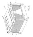
- a solid oxide fuel cell system 10 in accordance with the present invention comprises a stack 12 of fuel cell cassettes 14, each having electrodes and an electrolyte layer as know in the art (also referred to herein as “electrochemically active cell repeating units”), and including at least one electrochemically inactive unit (hereinafter referred to as a "dummy cassette") 26 positioned as described below, stack 12 having a longitudinal axis 13; a distributor manifold 16 supportive of stack 12; and a spring subassembly 18 including tie rods 20 for attaching spring subassembly 18 to distribution manifold 16, thereby binding system 10 together.
- Assembly alignment tabs 22 and cassette electrical terminals 24 are also present as described below but are not visible in FIG. 1 .
- thermocouple In an operating SOFC stack, measuring the gas stream temperatures can be inaccurate and misleading, since there is averaging of gas stream temperature and heat loss from a cell to an adjacent thermocouple. Inserting a thermocouple into an electrochemically active cell unit may affect stack performance, may electrically short adjacent cell repeating units, and may lead to gas leaks. However, knowing the actual cell temperature and temperature distribution at one or more levels of a stack improves understanding of stack operation and can improve stack control.
- Stack 12 incorporates one or more dummy cassettes 26 (combination of 26a, FIG. 4 , and 26b, FIG. 5 ) that contains one or more sensors 28 ( FIG. 3 ), preferably thermocouples, in a plane transverse of longitudinal axis 13 that is hermetically isolated from the stack gas streams.
- Dummy cassette 26 passes electrical current from one adjacent electrochemically active cell repeating unit 14 to the other electrochemically active cell repeating unit 14 with minimal voltage loss.
- the thermocoupled dummy cassette 26 is mostly solid, thin, and metallic so that it has minimal influence on the temperature distribution of adjacent cell repeating units.
- thermocouples Since the electrically and thermally conductive faces of the thermocoupled dummy cassette are in very close proximity to the operating cells, the temperatures and temperature distribution across the plane of the thermocoupled dummy cassette are almost exactly the same as in the adjacent active cells. Thus, providing a plurality of sensors 28, such as thermocouples, with their measuring tips at different locations in the plane of dummy cassette 26 affords insight into temperature distributions within the stack during stack design development; and ultimately, one or more thermocouples can be used in a production stack for stack operation feedback for system control purposes.
- thermocoupled dummy cassette 26 (TDC) consists of two or three principal components.
- a first or carrier plate 30 is thicker than the sheathed thermocouple 28 and has channels 32 formed into it that locate the thermocouples. One end of each channel is located at the desired measurement point, the other end opens to an edge 34 of plate 30. The channels follow a smooth path from the edge to the measuring point so that the thermocouples can be easily inserted after the TDC plates are joined into an assembly, or replaced if necessary. Sensor leads 29 extend from the ends of channels 32.
- First plate 30 is substantially solid sheet metal, with the exception of the narrow thermocouple channels, for good electrical and thermal conductivity.
- a second or upper plate 36 provides an electrical contacting surface and sealing surface to one adjacent active repeating unit above the TDC.
- a third or lower plate 38 may be used to provide an electrical contacting surface and sealing surface to the other adjacent active repeating unit below the TDC.
- All three plates 30,36,38 have through-holes 40 that correspond to the gas supply and return chimneys in the active repeating units of stack 12.
- the two or three plates are metallurgically bonded together (brazed or welded) so that the holes for the gas supply and return chimneys are hermetically sealed; therefore, the gas streams pass through the TDC without leaking into or out of the TDC.
- the plates are also joined in such a way as to provide a highly electrically conductive path through the TDC.
- the TDC is relatively thin in the vertical or axial (Z) direction, it is a very good thermal conductor in the Z direction, but relatively poor in the X-Y plane; this enables the TDC to accurately reflect the temperature and temperature distribution in the X-Y plane of the adjacent active repeating units.
- Stack 12 is assembled on a distribution manifold 16 preferably fabricated by casting from stainless steel (to match the CTE of the stack components) and finish-machined to final dimensions.
- a dummy cassette 26, is assembled adjacent an electrochemically active cell repeating unit 14 with a glass seal interposed therebetween.
- the glass seal is the same type as is used between functional electrochemically active cell repeating units 14 in the SOFC stack; the seal contains the fuel gas and air streams between repeating units and provides an adhesive, electrically insulating, mechanical bond between repeating units.
- the glass seal provides the same gas- tight bond joint between manifold 16 and the first component of the stack which effectively bonds the completed stack to the manifold.
- Manifold 16 then serves as the build platform for stack 12, a supporting carrier for stack 12 after assembly, and as a mounting interface between stack 12 and the SOFC system hardware. Manifold 16 also provides for a simple gas-tight attachment to the SOFC system plumbing and distributes the fuel gas and air streams to the stack internal manifolds.
- the glass seals are added in a green state: unsintered glass particles in an organic binder carrier material.
- the glass seals, along with the stack assembly, are then subjected to a high temperature sintering process to achieve their final dimension and gas-tight bonding properties.
- the seals shrink substantially in thickness and become somewhat liquidous as the organic carrier is destroyed. Therefore the stack assembly shrinks substantially in height, and all the repeating units must be restrained to prevent them from "floating" laterally out of their intended positions.
- At least one, and preferably two, assembly alignment tab 22 is added to the exterior perimeter of the components; for example, a first tab with a hole and a second tab with a slot at opposite locations to assure correct orientation of each cassette.
- Ceramic rods (not shown) are inserted through these features and into a locating hole in a reference element such as the base manifold to provide guiding and locating during the sintering process. The rods may be removed after sintering if desired.
- each repeating unit 14 is provided with at least one, and preferably two, voltage terminal 24 formed from the metal structure of that unit.
- a mating terminal (not shown) is preassembled with a mechanical joint or metallurgical bond to the voltage sensing test equipment, preferably computerized, using high volume wiring harness assembly techniques. The mating terminal is also mechanically joined or metallurgically bonded to voltage terminal 24.
- a low resistance (particularly at the high operating temperature of the stack) joint between the sensing wire and repeating unit is required for accurate voltage measurement (to 0.01 volt).
- the glass seals After sintering, the glass seals provide sturdy bonded joints between the components of the completed stack assembly. However, when stack 12 is cooled to room temperature from its operating temperature of 700°C to 800°C, residual temperature gradient-induced stresses within the components may cause tensile stresses within the glass joints that exceed the tensile strength of the joint. Since the glass seal joints are much stronger in compression than in tension, it is desirable to maintain a compressive load on the SOFC stack (and thus on the seal joints) at all times through the remainder of its life. In the prior art, this was accomplished with an end plate held in place with bolts and torqued to provide a clamping load.
- the present stack assembly is provided with a low profile spring subassembly 18 that provides a continuous compressive load even at SOFC operating temperatures.
- the present arrangement is simplified considerably over a prior art arrangement disclosed in US Patent No. 7,001,685 and described above.
- the present arrangement is bolted directly to the distribution manifold rather than to a base plate and comprises first and second leaf springs 42,44 fabricated from metal alloys with high temperature creep resistance that are assembled one on top of the other.
- Two springs are used to achieve the desired spring rate while keeping the spring stresses below the creep limit. Depending on load and spring rate requirements, one spring may be sufficient or more than two may be required.
- the uppermost spring 44 is larger than the footprint of stack 12, and the end is formed, or a stiffener added, to prevent bending perpendicular to the desired bending direction.
- Tie rods 20 which pass through upper spring 44 and are anchored to distribution manifold 16 and are tensioned to pull the ends of spring 44 to a desired deflection to thereby load the spring assembly.
- Tie rods 20 may be screws, threaded rod, or headed fixed length rods fabricated from a high temperature metal alloy.
- Lower spring 42 applies load to a stiff load plate 46 fabricated from a high temperature metal alloy or low cost ceramic (such as alumina or ZTA) to distribute the spring load uniformly over the stack footprint area.
Landscapes
- Chemical & Material Sciences (AREA)
- Life Sciences & Earth Sciences (AREA)
- Engineering & Computer Science (AREA)
- Manufacturing & Machinery (AREA)
- Sustainable Development (AREA)
- Sustainable Energy (AREA)
- Chemical Kinetics & Catalysis (AREA)
- Electrochemistry (AREA)
- General Chemical & Material Sciences (AREA)
- Inorganic Chemistry (AREA)
- Fuel Cell (AREA)
Applications Claiming Priority (1)
| Application Number | Priority Date | Filing Date | Title |
|---|---|---|---|
| US12/629,118 US20110129754A1 (en) | 2009-12-02 | 2009-12-02 | Structure for Forming a Solid Oxide Fuel Cell Stack |
Publications (2)
| Publication Number | Publication Date |
|---|---|
| EP2330673A2 true EP2330673A2 (de) | 2011-06-08 |
| EP2330673A3 EP2330673A3 (de) | 2013-04-03 |
Family
ID=43799544
Family Applications (1)
| Application Number | Title | Priority Date | Filing Date |
|---|---|---|---|
| EP10191727A Withdrawn EP2330673A3 (de) | 2009-12-02 | 2010-11-18 | Struktur zum Bilden eines Festoxidbrennstoffzellenstapels |
Country Status (2)
| Country | Link |
|---|---|
| US (1) | US20110129754A1 (de) |
| EP (1) | EP2330673A3 (de) |
Cited By (3)
| Publication number | Priority date | Publication date | Assignee | Title |
|---|---|---|---|---|
| FR3050875A1 (fr) * | 2016-04-27 | 2017-11-03 | Snecma | Pile a combustible et ensemble de generation de courant |
| CN110809832A (zh) * | 2017-07-26 | 2020-02-18 | 宝马股份公司 | 用于燃料电池堆的检测设备 |
| EP3686978A4 (de) * | 2017-09-22 | 2020-11-18 | Nissan Motor Co., Ltd. | Federelement, brennstoffzelleneinheit, brennstoffzellenstapel und verfahren zur herstellung eines brennstoffzellenstapels |
Families Citing this family (4)
| Publication number | Priority date | Publication date | Assignee | Title |
|---|---|---|---|---|
| US8232017B2 (en) * | 2007-06-28 | 2012-07-31 | Delphi Technologies, Inc. | Fuel cell stack including non-fuel cell cassette |
| DE102014208948B4 (de) | 2014-05-12 | 2024-02-08 | Audi Ag | Bipolarplatte, Brennstoffzelle, Stapel aus Brennstoffzellen und Vorrichtung zur Ausrichtung von Bipolarplatten |
| JP6359366B2 (ja) * | 2014-07-11 | 2018-07-18 | 日本特殊陶業株式会社 | 燃料電池スタック、燃料電池モジュール及び燃料電池 |
| WO2022101662A1 (en) * | 2020-11-12 | 2022-05-19 | Ceres Intellectual Property Company Limited | Analog stack for debugging sofc system |
Citations (2)
| Publication number | Priority date | Publication date | Assignee | Title |
|---|---|---|---|---|
| US453209A (en) | 1891-06-02 | Advertising-vehicle | ||
| US7001685B2 (en) | 2002-06-24 | 2006-02-21 | Delphi Technologies, Inc. | Fuel cell stack assembly load frame with compression spring |
Family Cites Families (5)
| Publication number | Priority date | Publication date | Assignee | Title |
|---|---|---|---|---|
| US7125540B1 (en) * | 2000-06-06 | 2006-10-24 | Battelle Memorial Institute | Microsystem process networks |
| US7270906B2 (en) * | 2002-06-24 | 2007-09-18 | Delphi Technologies, Inc. | Solid-oxide fuel cell module for a fuel cell stack |
| KR20050111625A (ko) * | 2003-03-31 | 2005-11-25 | 가부시키가이샤 지에스 유아사 코포레이션 | 직접 메탄올형 연료전지 및 그 연료극의 용출방지방법,품질관리방법, 운전방법 |
| US20090004532A1 (en) * | 2007-06-28 | 2009-01-01 | Haltiner Jr Karl J | Dummy cassettes for a solid oxide fuel cell stack |
| DE102007061061A1 (de) * | 2007-12-14 | 2009-06-18 | Volkswagen Ag | Brennstoffzellenstapel |
-
2009
- 2009-12-02 US US12/629,118 patent/US20110129754A1/en not_active Abandoned
-
2010
- 2010-11-18 EP EP10191727A patent/EP2330673A3/de not_active Withdrawn
Patent Citations (2)
| Publication number | Priority date | Publication date | Assignee | Title |
|---|---|---|---|---|
| US453209A (en) | 1891-06-02 | Advertising-vehicle | ||
| US7001685B2 (en) | 2002-06-24 | 2006-02-21 | Delphi Technologies, Inc. | Fuel cell stack assembly load frame with compression spring |
Cited By (6)
| Publication number | Priority date | Publication date | Assignee | Title |
|---|---|---|---|---|
| FR3050875A1 (fr) * | 2016-04-27 | 2017-11-03 | Snecma | Pile a combustible et ensemble de generation de courant |
| CN110809832A (zh) * | 2017-07-26 | 2020-02-18 | 宝马股份公司 | 用于燃料电池堆的检测设备 |
| US11424472B2 (en) | 2017-07-26 | 2022-08-23 | Bayerische Motoren Werke Aktiengesellschaft | Testing device for a fuel cell stack |
| CN110809832B (zh) * | 2017-07-26 | 2022-11-29 | 宝马股份公司 | 用于燃料电池堆的检测设备和方法 |
| EP3686978A4 (de) * | 2017-09-22 | 2020-11-18 | Nissan Motor Co., Ltd. | Federelement, brennstoffzelleneinheit, brennstoffzellenstapel und verfahren zur herstellung eines brennstoffzellenstapels |
| US11411275B2 (en) | 2017-09-22 | 2022-08-09 | Nissan Motor Co., Ltd. | Spring member, fuel cell unit, fuel cell stack, and method for manufacturing fuel cell stack |
Also Published As
| Publication number | Publication date |
|---|---|
| US20110129754A1 (en) | 2011-06-02 |
| EP2330673A3 (de) | 2013-04-03 |
Similar Documents
| Publication | Publication Date | Title |
|---|---|---|
| EP2330673A2 (de) | Struktur zum Bilden eines Festoxidbrennstoffzellenstapels | |
| US7913572B2 (en) | Integrated multi-measurement system for measuring physical properties of gas diffusion layer for polymer electrolyte fuel cell with respect to compression | |
| EP1710857A2 (de) | Herstellungsvervahren für Brennstoffzellenstapel | |
| CN112068019B (zh) | 一种平板型sofc电流密度分布式端板测试结构及测试方法 | |
| US8720252B2 (en) | Quality control apparatus for gas diffusion layer for fuel cells | |
| EP1851817B1 (de) | Brennstoffzellenstapel mit integriertem stromkollektor und elektrischer komponentenplatte | |
| US10497949B2 (en) | Electro-chemical reaction unit and fuel cell stack | |
| CN101223664A (zh) | 固体氧化物燃料电池堆 | |
| US20050215124A1 (en) | Fuel cell voltage monitoring system and associated electrical connectors | |
| JP2014522557A (ja) | 燃料電池バイパスダイオード構造及び取付け方法 | |
| Mench et al. | In situ temperature distribution measurement in an operating polymer electrolyte fuel cell | |
| Wuillemin et al. | Investigation of local electrochemical performance and local degradation in an operating solid oxide fuel cell | |
| KR20020020890A (ko) | 고분자전해질형 연료전지와 그 사용방법 | |
| JP2019169240A (ja) | 電気化学反応セルスタックの運転方法および電気化学反応システム | |
| EP3787083A1 (de) | Verbundstoff mit zellstapel mit elektrochemischer reaktion | |
| US20240085365A1 (en) | Sensors | |
| EP3070461B1 (de) | Impedanz-verfahren zur berechnung der protonenleitfähigkeit einer protonleitenden membran und protonenleitfähigkeitsmessvorrichtung | |
| JP7530626B2 (ja) | 電気化学単セル | |
| JP2006140166A (ja) | 燃料電池セルモニタ装置 | |
| JP2006140166A5 (de) | ||
| Tanaka et al. | In situ monitoring of cell deformation during operation in solid oxide fuel cells | |
| JP2021039825A (ja) | Sofcスタック評価用ホルダ | |
| KR20100138424A (ko) | 연료전지용 전극막 어셈블리 사전 검수 장치 및 방법 | |
| JP5829580B2 (ja) | 燃料電池用電位測定装置 | |
| JP2010271291A (ja) | イオン伝導度の測定装置、およびイオン伝導度の測定方法 |
Legal Events
| Date | Code | Title | Description |
|---|---|---|---|
| PUAI | Public reference made under article 153(3) epc to a published international application that has entered the european phase |
Free format text: ORIGINAL CODE: 0009012 |
|
| AK | Designated contracting states |
Kind code of ref document: A2 Designated state(s): AL AT BE BG CH CY CZ DE DK EE ES FI FR GB GR HR HU IE IS IT LI LT LU LV MC MK MT NL NO PL PT RO RS SE SI SK SM TR |
|
| AX | Request for extension of the european patent |
Extension state: BA ME |
|
| PUAL | Search report despatched |
Free format text: ORIGINAL CODE: 0009013 |
|
| AK | Designated contracting states |
Kind code of ref document: A3 Designated state(s): AL AT BE BG CH CY CZ DE DK EE ES FI FR GB GR HR HU IE IS IT LI LT LU LV MC MK MT NL NO PL PT RO RS SE SI SK SM TR |
|
| AX | Request for extension of the european patent |
Extension state: BA ME |
|
| RIC1 | Information provided on ipc code assigned before grant |
Ipc: H01M 8/24 20060101AFI20130226BHEP Ipc: H01M 8/04 20060101ALI20130226BHEP Ipc: H01M 8/02 20060101ALI20130226BHEP |
|
| STAA | Information on the status of an ep patent application or granted ep patent |
Free format text: STATUS: THE APPLICATION IS DEEMED TO BE WITHDRAWN |
|
| 18D | Application deemed to be withdrawn |
Effective date: 20131005 |