EP2330352A1 - Kamin - Google Patents
Kamin Download PDFInfo
- Publication number
- EP2330352A1 EP2330352A1 EP10193261A EP10193261A EP2330352A1 EP 2330352 A1 EP2330352 A1 EP 2330352A1 EP 10193261 A EP10193261 A EP 10193261A EP 10193261 A EP10193261 A EP 10193261A EP 2330352 A1 EP2330352 A1 EP 2330352A1
- Authority
- EP
- European Patent Office
- Prior art keywords
- heat
- jacket
- fireplace
- storing
- metal jacket
- Prior art date
- Legal status (The legal status is an assumption and is not a legal conclusion. Google has not performed a legal analysis and makes no representation as to the accuracy of the status listed.)
- Granted
Links
- 229910052751 metal Inorganic materials 0.000 claims abstract description 65
- 239000002184 metal Substances 0.000 claims abstract description 65
- 239000003546 flue gas Substances 0.000 claims abstract description 53
- UGFAIRIUMAVXCW-UHFFFAOYSA-N Carbon monoxide Chemical compound [O+]#[C-] UGFAIRIUMAVXCW-UHFFFAOYSA-N 0.000 claims abstract description 25
- 238000002485 combustion reaction Methods 0.000 claims abstract description 14
- 239000000463 material Substances 0.000 claims abstract description 7
- 239000004575 stone Substances 0.000 claims description 49
- 238000002347 injection Methods 0.000 claims description 19
- 239000007924 injection Substances 0.000 claims description 19
- 230000000630 rising effect Effects 0.000 claims description 13
- 238000005338 heat storage Methods 0.000 claims description 8
- 230000001788 irregular Effects 0.000 claims description 4
- 238000004140 cleaning Methods 0.000 claims description 2
- 238000012423 maintenance Methods 0.000 claims 1
- 238000010438 heat treatment Methods 0.000 description 23
- 239000007789 gas Substances 0.000 description 9
- 239000007787 solid Substances 0.000 description 6
- 239000002023 wood Substances 0.000 description 6
- 239000000779 smoke Substances 0.000 description 4
- 230000033228 biological regulation Effects 0.000 description 2
- 229910002091 carbon monoxide Inorganic materials 0.000 description 2
- 238000005266 casting Methods 0.000 description 2
- 230000002035 prolonged effect Effects 0.000 description 2
- 239000000243 solution Substances 0.000 description 2
- 230000001668 ameliorated effect Effects 0.000 description 1
- 230000015572 biosynthetic process Effects 0.000 description 1
- 239000011449 brick Substances 0.000 description 1
- 238000003776 cleavage reaction Methods 0.000 description 1
- 230000000295 complement effect Effects 0.000 description 1
- 150000001875 compounds Chemical class 0.000 description 1
- 238000010276 construction Methods 0.000 description 1
- 238000009826 distribution Methods 0.000 description 1
- 230000000694 effects Effects 0.000 description 1
- 238000005516 engineering process Methods 0.000 description 1
- 230000002708 enhancing effect Effects 0.000 description 1
- 230000036541 health Effects 0.000 description 1
- 230000006872 improvement Effects 0.000 description 1
- 230000006698 induction Effects 0.000 description 1
- 238000009434 installation Methods 0.000 description 1
- 238000004519 manufacturing process Methods 0.000 description 1
- 238000000034 method Methods 0.000 description 1
- 230000007017 scission Effects 0.000 description 1
- 239000000344 soap Substances 0.000 description 1
- 230000008646 thermal stress Effects 0.000 description 1
- 230000007704 transition Effects 0.000 description 1
Images

Classifications
-
- F—MECHANICAL ENGINEERING; LIGHTING; HEATING; WEAPONS; BLASTING
- F24—HEATING; RANGES; VENTILATING
- F24B—DOMESTIC STOVES OR RANGES FOR SOLID FUELS; IMPLEMENTS FOR USE IN CONNECTION WITH STOVES OR RANGES
- F24B1/00—Stoves or ranges
- F24B1/20—Ranges
- F24B1/24—Ranges with built-in masses for heat storage or heat insulation
Definitions
- the invention relates to the fireplace defined in the preamble of claim 1.
- the fireplaces designated for heating are either heat-storing fireplaces that radiate heat slowly and for a long time, or stoves that radiate heat quickly at over-power.
- This invention relates predominantly to the stove-type fireplaces and to the improvement of their combustion properties and heating properties.
- the conventional stove is a metal jacket with wood being burnt inside that transfers the heat to the surrounding space.
- the heating is quick, but there is heat only as long as the fire is burning.
- the heat of only one metal jacket and the consequent safety risk also constitute a problem.
- These properties have been tried to be ameliorated by adding around and above the fire box of the stove a heat-storing mass, in general fireproof casting mass, but also suitable natural stone. With these, the heat-storing capacity and heat-release time of the stove have been enhanced, while the temperature of the exterior jacket has been lowered to a safer level.
- the fact that it has not been possible to transfer the heat energy quickly enough from the flue gases of the stove to the heat-storing masses has still remained as a problem.
- the size and weight of the fireplace easily become obstacles to a productive solution.
- the corresponding problems relating to the heat-storage and heat-release are also present in sauna stoves.
- An objective of the invention is to eliminate the drawbacks referred to above.
- an objective of the invention is to disclose a new fireplace structure which encompasses the good properties of a conventional stove that radiates heat quickly, added with pure and complete combustion, durability and good heat-storing and heat-release properties. Furthermore, an objective of the invention is to disclose a sauna stove with the corresponding good properties.
- the fireplace according to the invention is characterized by what has been presented in claim 1.
- the invention relates to a fireplace including a fire box provided with a grate and a door, surrounded by a fire box jacket and having combustion air supply and a throat to remove the flue gases.
- a vertical metal jacket is disposed after the throat and above the fire box, leading the flue gases upwards.
- Inside the metal jacket there is a substantially continuous heat-storing mass of a well heat-storing material so as to provide for the formation of flue gas ducts between the metal jacket and the heat-storing mass, the flue gas ducts extending substantially for the entire width and entire height of the mass and the jacket, so that the hot gases rise along the ducts and release the heat partially to the metal jacket and partially to the heat-storing mass.
- the metal jacket and the fire box jacket are both surrounded by the exterior jacket of the fireplace.
- the shape of the metal jacket may be a circular cylinder, other round cylinder, it may have a square or a rectangular cross section or it may even be a square with rounded angles.
- An essential feature is the vertical straight space so that the heavy well heat-storing pieces of mass can be installed and, if necessary, removed from the top.
- the heat-storing mass may even be formed from one solid piece of mass of soapstone or suitable casting mass.
- the heat-storing mass is nonetheless formed by superpositioned slabs, such as suitably soapstone slabs of a uniform thickness, extending for almost the entire horizontal cross section of the inside of the metal jacket.
- the individual slabs weigh suitably between 5 and 20 kg, depending on the area and thickness of the slabs.
- the cleavage of the stone in the slabs may be suitably so chosen that the heat is stored in the slabs efficiently, quickly and simultaneously from all edges toward the center of the slabs.
- the thicknesses of the soapstone slabs to be stacked one on the other may vary freely according to the available slabs. Similarly, as the individual slabs of a uniform thickenss are disposed closely against each other, the structure stores the heat well even if some of the slabs therebetween would crack.
- the important feature in the invention is that the flue gases around the heat-storing mass are equally hot and that the flue gas flows around the heat-storing mass have an equal volume. This way, the heat-storing mass heats up evenly and its heat-storing capacity is the most efficient.
- suitable flow guides such as flaps, a ribbing, channels or an equivalent structure.
- thermoelectric cooler In a similar manner, provided above the heat-storing mass are preferably suitable top guides guiding the rising gas flows so that the draft caused by the discharge flue can be distributed evenly around the heat-storing mass.
- the cross-sectional shape of the metal jacket and the shape of the heat-storing mass or the separate slabs of the heat-storing mass are not necessarily strictly bound to each other.
- the individual soapstone slabs of a uniform thickness may be shaped as squares, rounded squares, circles, regular or irregular polygons or they may be irregular at the edges. It is only essential that they fill the interior delimited by the metal jacket to the extent that flue gas ducts are formed between the heat-storing mass and the metal jacket with flow resistances of the same order, disposed relatively evenly for the entire perimeter and height of the interior space. This way, the heat-storing mass heats up evenly everywhere from its edges toward the center throughout the entire heating process.
- the surrounding metal jacket heats up evenly over its entire area and releases heat efficiently and quickly to the outside air.
- the soapstone slabs suitably one on the other and rotating them to different positions in the plane, a network of smoke ducts with flow resistances of about the same level over the entire circumference can be made to circulate the entire inner surface of the metal jacket. This way, the hot flue gases are distributed evenly over the entire area between the metal jacket and the soapstone slabs to realize as efficient heat transfer as possible.
- the metal jacket is provided on the top with an opening and tightly closing cover.
- This provides for easy installation of the heat-storing mass, such as soapstone slabs, and easy and simple cleaning at regular intervals.
- the stone slabs may be taken out and cleaned and, at the same time, the possibly broken ones may be changed for new. This way, the heat-storing capacity of the fireplace may be easily maintained at the maximum year after year.
- the airspace between the metal jacket and the exterior jacket of the fireplace includes a non-continuous stone jacket having a large heat-storing surface.
- a non-continuous stone jacket is meant in this context that the stone jacket is not a compact and continuous stone slab, but is formed from stone mass, i.e. a large set of separate stone pieces which mainly have only a spot contact to each other.
- a stone mass like this has a large heat transfer surface with air surrounding the stones, notably larger than that of a compact and continuous stone mass.
- the stone jacket extends above the grate to both sides of the metal jacket, to the back wall, over the door to the front wall and to the cover.
- the exterior jacket may be a gridded structure or suitable perforated plate, so that the heat stored in the stone mass is able to freely flow with air flows to the surrounding airspace.
- the exterior jacket is a continuous metal sheet. In this case, more heat can be stored in the stone jacket, and by opening and closing the air flow ports on the exterior jacket the surrounding airspace may be heated at different outputs.
- an air gap arranged to keep the stones of the stone jacket off from the hot metal jacket. This may be realized for only part of the area of the metal jacket, for example for an area where the temperature of the metal jacket is above 500°C. This way, strong point-type thermal stresses on stones are prevented, so that no minerological changes are formed therein and the stones can be made to last unbroken.
- the stone jacket is preferably located in the fireplace about from the level of the grate upwards, substantially over the entire area of the metal jacket of the fireplace. Its thickness may vary according to the desired heat-storage properties of the fireplace, for example so that the thickness on the vertical walls of the fireplace may be several decameters. On the top the layer thickness of the stone jacket may instead be preferably at least half a meter and even more than one meter.
- the stone pieces used in the stone jacket may have a round shape and be of the same or variable sizes. Similarly, they may be irregular sawn or split crushed stone. In any case, they do not have uniform and matching complementary surfaces, so that they mainly have only a spot contact to each other. This way, large numbers of air cavities of different shapes and different sizes are formed between the stone pieces.
- the external surfaces of the stone pieces form a large heat-receiving heat delivery surface, compared with a surface formed by a solid stone wall built in the same volume.
- the heat-storage capacity and the heat-release capacity of the stone jacket are notably quicker than those of a solid jacket.
- the fireplace When the exterior jacket of the fireplace in the area of the stone jacket is a gridded structure, or the stone jacket is open and visible at least on the top of the fireplace, the fireplace may be used as a sauna stove.
- the fireplace may have a solid exterior jacket provided only with air flow ports and made of a metal sheet, soapstone slabs, tile or equivalent.
- the fireplace is a stove, i.e. it may be used to quickly heat the surrounding room area, but, thanks to the inventive structure, it also stores heat efficiently during heating, which provides for long and steady heat release also after the fire has gone out in the fire box.
- the heat-storing mass such as the soapstone slabs
- a suitable insulating sheet preventing direct contact of the hottest gases and the combustion process with the lowest soapstone slab.
- the soapstone used does not necessarily have to be the most resistant and valuable soapstone grade. This way, different kinds of slabs of various thicknesses left over from another manufacturing process may well be used in the fireplace according to the invention.
- the quickly and efficiently heat-storing structure according to the invention may be used as a fixed and essential part in different kinds of stoves and sauna stoves. Similarly, it may be used as a retrofitted accessory in various existing stoves.
- an opening and closing damper is provided above the heat-storing mass in the discharge flue for closing the discharge flue and so preventing the hot gas flows to the flue via heat-storing mass after heating. Because the flow path leading from fire box to the flue may nevertheless not be closed completely according to the safety regulations, due to the carbon monoxide hazard, a by-pass duct is provided from the fire box to the discharge flue. It is also preferably linked to the above-mentioned damper in such a manner that as the damper is open the by-pass duct is closed, and as the damper is closed the by-pass duct is open.
- suction guides below the heat-storing mass and, respectively, injection guides above the heat-storing mass for distributing the hot chimney gases evenly on the heat-storing surfaces of the heat-storing mass.
- the negative pressure caused by the draft of the flue sucks the flue gases in the guidance and direction of the suction guides from the fire box via the throat in a controlled way and evenly, distributing heat on all heat-storing surfaces of the heat-storing mass.
- the injection guides above the heat-storing mass combine the flue gas flows rising from around the heat-storing mass and align them evenly as parallel flows into the discharge flue.
- the parallel and converging flue gas flows meet and intensify each other according to the injection principle, this way enhancing the equivalence of the speeds of the flue gas flows from different sides of the heat-storing mass.
- the suction guide includes horizontal ribs or equivalent blades or planar guides in the horizontal direction for guiding the flue gases under the heat-storing mass in the horizontal direction.
- the number of the ribs may vary, preferably being 4 to 10.
- the suction guide includes, in addition to the horizontal ribs, vertical ribs in the area of the throat for guiding the flue gases and limiting their swirling already in the area of the throat, i.e. in the area of the rising motion of the flue gases, so that as they turn to the area of the horizontal ribs they have already been divided into even flows.
- the injection guide disposed above the heat-storing mass includes horizontal ribs or equivalent blades or guides in the horizontal direction.
- the flue gases rising from the heat-storage channels onto the heat-storing mass may be collected and directed evenly toward the discharge channel.
- the injection guide also includes parallel vertical ribs suitably in the area of the discharge channel, parallel injection flows can be formed to the discharge channel and therefrom to the flue, intensifying and balancing the flue gas flows of different parts of the heat-storage channel.
- the heat-storage channel includes dividing walls extending from the suction guide to the injection guide to divide the rising heat-storage channel into several separate subchannels. This way, the corresponding horizontal ribs of the suction guide and the induction guide are connected by the dividing walls, so that separate flue gas flow channels extend from the throat to the discharge channel.
- a steady and continuous flue gas flow can be provided on all heat-storing surfaces of the heat-storing mass.
- the fireplace according to the invention has considerable advantages as compared to the prior art.
- the same fireplace may be used in a versatile manner in both quick as well as slow and prolonged heating.
- wood may be burnt in the stove at a high combustion temperature with a high combustion utility function, in which case the stove also produces heat at a high output.
- the heat can be stored partially in the inventive interior masses and also in the optionally used surrounding stone mass from which it is released steadily or in another desired manner into the room space. Thanks to the construction, the heat-storing masses and the other structures of the stove are not overheated and thus are not subject to a transition temperature where their thermal properties would be weakened, so the stove will keep its quick heat-storing capacity for decades.
- the same inventive structure in sauna stoves provides for quick and efficient burning of wood as well as prolonged and steady heat.
- the invention provides for even distribution of the hot flue gas flows on all heat-storing surfaces of the heat-storing mass. This way, the entire heat-storing capacity of the fireplace can be efficiently utilized in the invention. Furthermore, the invention provides for as good an overall efficiency as possible in connection with pure and complete combustion.
- the invention has successfully combined the conventional fireplace applicable for quick heating and the massive fireplace having good and quick heat-storing properties with a quick, efficient combustion process according to the modern technology that produces pure flue gases.
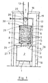
- Fig. 1 presents one fireplace according to the invention as a sectional illustration, having a grate 1 and a fire box 2 thereon.
- the fire box is delimited from each side by a close-fitting metal jacket 3 and, naturally, from the front side by the door which is not shown in the sectional illustration.
- the combustion air supply is provided from below via the grate, and the removal of the flue gases is provided from above in the throat 4, in the top of the fire box.
- the metal jacket 3 of the fire box 2 extends upwards after the throat 4, in this embodiment as a metal jacket 5 with a round horizontal cross section, forming a cylindrical space.
- planar suction guides 6 Disposed in the area of the throat 4, as the space opens into the cylindrical space, are planar suction guides 6 for guiding the hot gas flow rising from the throat and for distributing it evenly over the entire area of the mounting jacket of the cylindrical space.
- the suction guide 6 includes horizontal ribs 26 and, in the area of the throat 27, vertical ribs 28, which together form dividing walls that guide, delimit and distribute the flue gases to distribute the equally strong and hot flue gases from the steady vertical rising flow of the area of the throat to different sides of the heat-storing mass.
- the horizontal ribs 26 of the suction guide 6 may form a lattice over the throat 27, extending between the opposed walls or from corner to corner and forming, at the same time, a supporting structure for the stone slabs 7 to be disposed thereon. It is also shown in Fig. 3 and 4 that there may be heat-storing material, such as soapstone slabs, around the metal jacket 5 to increase the heat-storing capacity of the fireplace.
- the suction guides and the insulating sheet together, or one or the other separately, form a supporting structure or include a separate supporting structure. Disposed on this supporting structure is a set of soapstone slabs 7 of a uniform thickness. Thicknesses between one slab 7 and the other may be different. The slabs extend almost over the entire area delimited by the metal jacket 5, so that relatively narrow flue gas ducts 8 are formed between them and the metal jacket 5, leading upwards from the fire box.
- the soapstone slabs 7 may vary in shape, or they may all be similar, for example substantially squares. However, they are preferably disposed, i.e.
- the flue gas ducts 8 are formed in a deviously, windingly or for example spirally rising manner between the soapstone slabs and the metal jacket. Furthermore, the flue gas ducts 8 are formed in such a manner that they have substantially equally high flow resistance throughout the entire circumference so as to distribute the flue gases substantially evenly over the entire circumference of the metal jacket 5.
- the insulating sheet 15 disposed below the soap stone slabs 7 covers the lower surface of the lowest soapstone slab 7 so that the hot and combustible gases circulate to the edges of the soapstone slab. This way, too intensive heating of the lowest soapstone slab is prevented.
- injection guides 10 Disposed on top of the soapstone slabs 7 are injection guides 10, substantially corresponding to the suction guides 6 at the bottom, for guiding the draft, i.e. the negative pressure, caused by the flue 13 evenly to each side of the heat-storing mass 7.
- the injection guides 10 include horizontal ribs 29 on top of the heat-storing mass for collecting the flue gases rising around the heat-storing mass to the discharge flue 13.
- the horizontal ribs 29 extend to the area of the discharge flue 13 as vertical ribs 30 which direct the parallel injection flows of flue gases into the flue.
- the exterior jacket 9 of the stove is a solid soapstone slab structure enclosed at the top by the cover 16 of the exterior jacket of the same material.
- An airspace 17 is formed between the exterior jacket 9 and the fire box jacket 3 and metal jacket 5.
- the airspace 17 is substantially closed and provided with an inflow valve 18 on the exterior jacket 9 at the bottom of the fireplace and with an outflow valve 19 at the top of the exterior jacket 9.
- Fig. 1 the structure of Fig. 1 includes a damper 20 installed in the discharge flue 13 for closing and opening it.
- a by-pass duct 21 is provided in connection with the operation of the damper.
- the by-pass duct 21 is a pipe of a relatively small flow cross section that separates from the top of the fire box 2 and runs upwards in the airspace 17 past the metal jacket 5 and the heat-storing mass 7 therein. It is arranged to end above the pivoting axle of the round damper 20 that rotates and hinges on its axle in the discharge flue 13. However, it is so close to the above-said pivoting axle that, when turned vertically, i.e. opened in the flow direction, the damper turns to the front of the by-pass duct 21, closing it.
- the surface of the damper 20 is provided with a small baffle or a flange 22 which primarily falls to the front of the mouth of the by-pass duct.
- the by-pass duct 21 opens, letting the possible carbon monoxide gases flow to the discharge flue 13 without the heat of the heat-storing mass 7 getting into the flue.
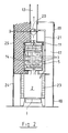
- Fig. 2 presents a second embodiment of the invention, comprising on top of the grate 1 and the fire box 2, in the manner equivalent to the embodiment of Fig. 1 , a metal jacket 5, a closing cover 11 and, inside the metal jacket, a set of soapstone slabs 7 of a uniform thickness, the thickness of the individual slabs yet being freely variable.
- the area of the fire box 2 in the fireplace is made of a heat-storing and fireproof material, such as soapstone or fire bricks 23.
- Fig. 2 is divided in the middle in two different embodiments.
- the exterior jacket is a solid metal sheet 24 at the height of the fire box 2 and, upwards therefrom, i.e. in the area of the metal jacket 5, the exterior jacket is a metallic meshwork 25 which extends as far as the top of the fireplace.
- the gap between the exterior jacket, i.e. the metallic meshwork, and the metal jacket 5 is filled with stone pieces, preferably of soapstone (dicing in the figure), so arranged in shape and positioning that they mainly have only a spot contact to each other and to the metallic meshwork. This way, air-spaces are formed between the stone pieces, and the external surfaces of the stone pieces form a large heat-storing area.
- an air gap 14 is formed in the area of the metal jacket 5 with a suitable mesh structure. This prevents direct contact of the stone pieces with the hotmost metallic surfaces of the structure. This way, durability and lifetime of the stones to be used are increased.
- a cover is not needed at all in this embodiment, but the stone pieces may be visible and bare on the top.
- the fireplace acts as a sauna stove, the visible stone pieces on the outside storing the heat conducted and transferred through the metal jacket 5, while part of it flows to the sauna space with air flows.
- part of the heat developed in the fire box 2 is stored in the heat-storing mass 7 inside the metal jacket 5, from which it is conducted slowly through the metal jacket 5 after the heating has been finished, keeping the sauna in the heated state for a long time.
- the exterior jacket 9 is a continuous metal jacket only comprising the inflow valve 18 and the outflow valve 19 according to the embodiment of Fig. 1 to realize even quicker heating of the surrounding airspace.
- This embodiment corresponds in many respects to a conventional stove provided with a metallic exterior jacket 9, having only an airspace 17 between the interior jacket and the exterior jacket.
- the stove acts as a quick heating device as the metal jacket partially radiates and partially conducts heat to the exterior jacket through air.
- it nevertheless also acts, according to the invention, as a heat-release-adjusting and heat-storing structure, realizing a long heating period, storing part of the heat in the heat-storing mass 7 in the middle of the stove.
- the heat which the conventional stove releases in efficient burning out to the smoke flue is stored by this inventive structure in the middle of the stove, releasing it slowly and steadily after heating to the room space. Therefore, the essential feature in the described stove structure is that it may burn wood efficiently and quickly with the best utility function and the modern burning technique that enables pure flue gases.
- the stove does not heat up too much during heating, but stores and distributes the heat steadily with a long heating time.
- the inventive storing of heat is therefore based on the idea that the heat-storing mass may be relatively continuous and the heat is stored therein through the external surface.
- this external surface is further arranged to vary using slabs of different sizes, the heat-exchange surface of the heat-storing mass is made very large.
- the heat transfer may be intensified according to the embodiment of Fig. 2 by a channel provided through the heat-storing mass, i.e. the soapstone slabs 7 (broken line in the figure).
- a gate valve is further disposed in the channel, the channel may be used efficiently for example at the end of heating when the edges of the stone slabs are already very hot. In this manner, the terminal heat may be directly stored in the middle of the stones by opening the gate valve.
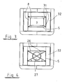
- Fig. 3 presents one embodiment of the invention that illustrates as a cross-section how the flue gas ducts 8 throughout the entire height of the heat-storing mass 7 comprise dividing walls 31, i.e. metal flanges. They start from the vertical ribs 28 of the suction guide 6 and end at the vertical ribs 30 of the injection guide 10. This way, separate flue gas flow channels are provided around the heat-storing mass 7, starting separately already from the area of the throat 27 and not ending and meeting until at the discharge flue 13.
- Fig. 5 presents in more detail one injection guide 10, or respectively, when turned around, one suction guide 6, according to the invention.
- the injection guide 10 includes a planar horizontal rib 29 or a horizontal blade, the height a of which corresponds substantially to the height of the space on top of the heat-storing mass 7 in which it is accommodated.
- the injection guide includes a planar vertical rib 30 or a vertical blade, the width b of which is equal to the radius of the discharge channel 13.
- the height c of the vertical rib is adapted so as to extend from the top of the mass 7 to a sufficient and considerable distance in the discharge channel, but not necessarily to the exterior of the fireplace structure.
- the lengths d of their horizontal ribs 2912 may be equal.
- Various combinations may nevertheless be built from the ribs according to need and welded together in the middle, the number of the ribs and the angles between them varying according to the shapes of the smoke ducts and the necessary flue gas flows.
- the lengths of the horizontal ribs 29 vary while the vertical ribs 13 are of the same size in all ribs.
- the suction guide according to Fig. 5 extends over the entire horizontal area between the heat-storing mass and the throat and at least over part of the height of the throat, possibly over the entire height of the throat.
Landscapes
- Engineering & Computer Science (AREA)
- Chemical & Material Sciences (AREA)
- Combustion & Propulsion (AREA)
- Mechanical Engineering (AREA)
- General Engineering & Computer Science (AREA)
- Solid-Fuel Combustion (AREA)
- Baking, Grill, Roasting (AREA)
Applications Claiming Priority (2)
| Application Number | Priority Date | Filing Date | Title |
|---|---|---|---|
| FI20096279A FI122079B (fi) | 2009-12-02 | 2009-12-02 | Tulisija |
| FI20105392A FI20105392A0 (fi) | 2010-04-15 | 2010-04-15 | Tulisija |
Publications (2)
| Publication Number | Publication Date |
|---|---|
| EP2330352A1 true EP2330352A1 (de) | 2011-06-08 |
| EP2330352B1 EP2330352B1 (de) | 2016-07-27 |
Family
ID=43827122
Family Applications (1)
| Application Number | Title | Priority Date | Filing Date |
|---|---|---|---|
| EP10193261.4A Active EP2330352B1 (de) | 2009-12-02 | 2010-12-01 | Kamin |
Country Status (2)
| Country | Link |
|---|---|
| EP (1) | EP2330352B1 (de) |
| RU (1) | RU2547853C2 (de) |
Families Citing this family (2)
| Publication number | Priority date | Publication date | Assignee | Title |
|---|---|---|---|---|
| RU170181U1 (ru) * | 2016-11-28 | 2017-04-18 | Владимир Викторович Шевяков | Каркасная кирпичная отопительная печь с улучшенными тепловыми характеристиками |
| RU170180U1 (ru) * | 2016-11-28 | 2017-04-18 | Владимир Викторович Шевяков | Отопительная печь с защитой от перегрева стенок топки |
Citations (3)
| Publication number | Priority date | Publication date | Assignee | Title |
|---|---|---|---|---|
| EP1150073A2 (de) * | 2000-04-28 | 2001-10-31 | Nunnanlahden Uuni Oy | Wärmespeicherkamin |
| EP1376014A2 (de) * | 2002-06-20 | 2004-01-02 | Nunnanlahden Uuni Oy | Ofen nach Art eines Kamins |
| EP2136144A2 (de) * | 2008-06-17 | 2009-12-23 | NunnaUuni Oy | Baustein eines Wärmespeichers und zugehöriger Wärmespeicher |
Family Cites Families (3)
| Publication number | Priority date | Publication date | Assignee | Title |
|---|---|---|---|---|
| US1771668A (en) * | 1928-05-21 | 1930-07-29 | Chemical Toilet Corp | Sheet-metal fireplace |
| RU2261400C1 (ru) * | 2004-02-25 | 2005-09-27 | Эмдин Дмитрий Михайлович | Отопительный камин экономичный деликатный многофункциональный (ок-эдм) |
| DE202008004705U1 (de) * | 2008-04-05 | 2008-07-17 | Martens, Jakob | Kombi-Kamin |
-
2010
- 2010-12-01 EP EP10193261.4A patent/EP2330352B1/de active Active
- 2010-12-01 RU RU2010148906/03A patent/RU2547853C2/ru active
Patent Citations (3)
| Publication number | Priority date | Publication date | Assignee | Title |
|---|---|---|---|---|
| EP1150073A2 (de) * | 2000-04-28 | 2001-10-31 | Nunnanlahden Uuni Oy | Wärmespeicherkamin |
| EP1376014A2 (de) * | 2002-06-20 | 2004-01-02 | Nunnanlahden Uuni Oy | Ofen nach Art eines Kamins |
| EP2136144A2 (de) * | 2008-06-17 | 2009-12-23 | NunnaUuni Oy | Baustein eines Wärmespeichers und zugehöriger Wärmespeicher |
Also Published As
| Publication number | Publication date |
|---|---|
| RU2547853C2 (ru) | 2015-04-10 |
| EP2330352B1 (de) | 2016-07-27 |
| RU2010148906A (ru) | 2012-06-10 |
Similar Documents
| Publication | Publication Date | Title |
|---|---|---|
| RU2347980C1 (ru) | Печь для бани | |
| EP2107315A2 (de) | Kamin | |
| RU2352865C1 (ru) | Печь для бани (варианты) | |
| CA2625536A1 (en) | Wood fired boiler | |
| EP2213945B1 (de) | Verbrennungsvorrichtung und verfahren zur erhöhung der wärmeabfuhr aus einer verbrennungsvorrichtung | |
| US8646441B2 (en) | Fume box for a domestic heating appliance using solid fuel | |
| US9683745B2 (en) | Small, high efficient wood stove | |
| EP2330352B1 (de) | Kamin | |
| RU2363888C1 (ru) | Водогрейный твердотопливный котел | |
| RU142739U1 (ru) | Отопительный котел | |
| KR101148696B1 (ko) | 펠렛 보일러 | |
| RU2546370C1 (ru) | Отопительный котел | |
| KR101448100B1 (ko) | 하이브리드 보일러 | |
| US4597376A (en) | Heat recovery hood | |
| KR101312963B1 (ko) | 화목연소장치 | |
| RU2661516C2 (ru) | Твердотопливный газогенераторный котёл | |
| RU2350845C1 (ru) | Печь | |
| RU2418243C1 (ru) | Печь для бани | |
| RU2702069C1 (ru) | Вертикальная колосниковая решетка топки котла | |
| EP1387984A1 (de) | Verfahren zum verbrennen von festbrennstoffen in einem brenner und vorrichtung zur durchführung des verfahrens | |
| RU66012U1 (ru) | Печь теплоаккумулирующая | |
| CN103528096B (zh) | 焚烧炉 | |
| RU2485414C2 (ru) | Котел отопления, работающий на дровах | |
| RU2079062C1 (ru) | Печь | |
| FI122176B (fi) | Tulisija |
Legal Events
| Date | Code | Title | Description |
|---|---|---|---|
| PUAI | Public reference made under article 153(3) epc to a published international application that has entered the european phase |
Free format text: ORIGINAL CODE: 0009012 |
|
| AK | Designated contracting states |
Kind code of ref document: A1 Designated state(s): AL AT BE BG CH CY CZ DE DK EE ES FI FR GB GR HR HU IE IS IT LI LT LU LV MC MK MT NL NO PL PT RO RS SE SI SK SM TR |
|
| AX | Request for extension of the european patent |
Extension state: BA ME |
|
| 17P | Request for examination filed |
Effective date: 20111208 |
|
| 17Q | First examination report despatched |
Effective date: 20150212 |
|
| GRAP | Despatch of communication of intention to grant a patent |
Free format text: ORIGINAL CODE: EPIDOSNIGR1 |
|
| INTG | Intention to grant announced |
Effective date: 20160126 |
|
| GRAS | Grant fee paid |
Free format text: ORIGINAL CODE: EPIDOSNIGR3 |
|
| GRAA | (expected) grant |
Free format text: ORIGINAL CODE: 0009210 |
|
| AK | Designated contracting states |
Kind code of ref document: B1 Designated state(s): AL AT BE BG CH CY CZ DE DK EE ES FI FR GB GR HR HU IE IS IT LI LT LU LV MC MK MT NL NO PL PT RO RS SE SI SK SM TR |
|
| REG | Reference to a national code |
Ref country code: GB Ref legal event code: FG4D |
|
| REG | Reference to a national code |
Ref country code: CH Ref legal event code: EP |
|
| REG | Reference to a national code |
Ref country code: AT Ref legal event code: REF Ref document number: 816120 Country of ref document: AT Kind code of ref document: T Effective date: 20160815 |
|
| REG | Reference to a national code |
Ref country code: IE Ref legal event code: FG4D |
|
| REG | Reference to a national code |
Ref country code: DE Ref legal event code: R096 Ref document number: 602010035002 Country of ref document: DE |
|
| REG | Reference to a national code |
Ref country code: SE Ref legal event code: TRGR |
|
| REG | Reference to a national code |
Ref country code: LT Ref legal event code: MG4D |
|
| REG | Reference to a national code |
Ref country code: NL Ref legal event code: MP Effective date: 20160727 |
|
| REG | Reference to a national code |
Ref country code: AT Ref legal event code: MK05 Ref document number: 816120 Country of ref document: AT Kind code of ref document: T Effective date: 20160727 |
|
| REG | Reference to a national code |
Ref country code: FR Ref legal event code: PLFP Year of fee payment: 7 |
|
| REG | Reference to a national code |
Ref country code: NO Ref legal event code: T2 Effective date: 20160727 |
|
| PG25 | Lapsed in a contracting state [announced via postgrant information from national office to epo] |
Ref country code: IT Free format text: LAPSE BECAUSE OF FAILURE TO SUBMIT A TRANSLATION OF THE DESCRIPTION OR TO PAY THE FEE WITHIN THE PRESCRIBED TIME-LIMIT Effective date: 20160727 Ref country code: IS Free format text: LAPSE BECAUSE OF FAILURE TO SUBMIT A TRANSLATION OF THE DESCRIPTION OR TO PAY THE FEE WITHIN THE PRESCRIBED TIME-LIMIT Effective date: 20161127 Ref country code: LT Free format text: LAPSE BECAUSE OF FAILURE TO SUBMIT A TRANSLATION OF THE DESCRIPTION OR TO PAY THE FEE WITHIN THE PRESCRIBED TIME-LIMIT Effective date: 20160727 Ref country code: FI Free format text: LAPSE BECAUSE OF FAILURE TO SUBMIT A TRANSLATION OF THE DESCRIPTION OR TO PAY THE FEE WITHIN THE PRESCRIBED TIME-LIMIT Effective date: 20160727 Ref country code: NL Free format text: LAPSE BECAUSE OF FAILURE TO SUBMIT A TRANSLATION OF THE DESCRIPTION OR TO PAY THE FEE WITHIN THE PRESCRIBED TIME-LIMIT Effective date: 20160727 Ref country code: RS Free format text: LAPSE BECAUSE OF FAILURE TO SUBMIT A TRANSLATION OF THE DESCRIPTION OR TO PAY THE FEE WITHIN THE PRESCRIBED TIME-LIMIT Effective date: 20160727 Ref country code: HR Free format text: LAPSE BECAUSE OF FAILURE TO SUBMIT A TRANSLATION OF THE DESCRIPTION OR TO PAY THE FEE WITHIN THE PRESCRIBED TIME-LIMIT Effective date: 20160727 |
|
| PG25 | Lapsed in a contracting state [announced via postgrant information from national office to epo] |
Ref country code: ES Free format text: LAPSE BECAUSE OF FAILURE TO SUBMIT A TRANSLATION OF THE DESCRIPTION OR TO PAY THE FEE WITHIN THE PRESCRIBED TIME-LIMIT Effective date: 20160727 Ref country code: PL Free format text: LAPSE BECAUSE OF FAILURE TO SUBMIT A TRANSLATION OF THE DESCRIPTION OR TO PAY THE FEE WITHIN THE PRESCRIBED TIME-LIMIT Effective date: 20160727 Ref country code: BE Free format text: LAPSE BECAUSE OF FAILURE TO SUBMIT A TRANSLATION OF THE DESCRIPTION OR TO PAY THE FEE WITHIN THE PRESCRIBED TIME-LIMIT Effective date: 20160727 Ref country code: GR Free format text: LAPSE BECAUSE OF FAILURE TO SUBMIT A TRANSLATION OF THE DESCRIPTION OR TO PAY THE FEE WITHIN THE PRESCRIBED TIME-LIMIT Effective date: 20161028 Ref country code: LV Free format text: LAPSE BECAUSE OF FAILURE TO SUBMIT A TRANSLATION OF THE DESCRIPTION OR TO PAY THE FEE WITHIN THE PRESCRIBED TIME-LIMIT Effective date: 20160727 Ref country code: PT Free format text: LAPSE BECAUSE OF FAILURE TO SUBMIT A TRANSLATION OF THE DESCRIPTION OR TO PAY THE FEE WITHIN THE PRESCRIBED TIME-LIMIT Effective date: 20161128 Ref country code: AT Free format text: LAPSE BECAUSE OF FAILURE TO SUBMIT A TRANSLATION OF THE DESCRIPTION OR TO PAY THE FEE WITHIN THE PRESCRIBED TIME-LIMIT Effective date: 20160727 |
|
| PG25 | Lapsed in a contracting state [announced via postgrant information from national office to epo] |
Ref country code: EE Free format text: LAPSE BECAUSE OF FAILURE TO SUBMIT A TRANSLATION OF THE DESCRIPTION OR TO PAY THE FEE WITHIN THE PRESCRIBED TIME-LIMIT Effective date: 20160727 Ref country code: RO Free format text: LAPSE BECAUSE OF FAILURE TO SUBMIT A TRANSLATION OF THE DESCRIPTION OR TO PAY THE FEE WITHIN THE PRESCRIBED TIME-LIMIT Effective date: 20160727 |
|
| REG | Reference to a national code |
Ref country code: DE Ref legal event code: R097 Ref document number: 602010035002 Country of ref document: DE |
|
| PG25 | Lapsed in a contracting state [announced via postgrant information from national office to epo] |
Ref country code: SM Free format text: LAPSE BECAUSE OF FAILURE TO SUBMIT A TRANSLATION OF THE DESCRIPTION OR TO PAY THE FEE WITHIN THE PRESCRIBED TIME-LIMIT Effective date: 20160727 Ref country code: DK Free format text: LAPSE BECAUSE OF FAILURE TO SUBMIT A TRANSLATION OF THE DESCRIPTION OR TO PAY THE FEE WITHIN THE PRESCRIBED TIME-LIMIT Effective date: 20160727 Ref country code: SK Free format text: LAPSE BECAUSE OF FAILURE TO SUBMIT A TRANSLATION OF THE DESCRIPTION OR TO PAY THE FEE WITHIN THE PRESCRIBED TIME-LIMIT Effective date: 20160727 Ref country code: CZ Free format text: LAPSE BECAUSE OF FAILURE TO SUBMIT A TRANSLATION OF THE DESCRIPTION OR TO PAY THE FEE WITHIN THE PRESCRIBED TIME-LIMIT Effective date: 20160727 Ref country code: BG Free format text: LAPSE BECAUSE OF FAILURE TO SUBMIT A TRANSLATION OF THE DESCRIPTION OR TO PAY THE FEE WITHIN THE PRESCRIBED TIME-LIMIT Effective date: 20161027 |
|
| PLBE | No opposition filed within time limit |
Free format text: ORIGINAL CODE: 0009261 |
|
| STAA | Information on the status of an ep patent application or granted ep patent |
Free format text: STATUS: NO OPPOSITION FILED WITHIN TIME LIMIT |
|
| 26N | No opposition filed |
Effective date: 20170502 |
|
| REG | Reference to a national code |
Ref country code: CH Ref legal event code: PL |
|
| GBPC | Gb: european patent ceased through non-payment of renewal fee |
Effective date: 20161201 |
|
| PG25 | Lapsed in a contracting state [announced via postgrant information from national office to epo] |
Ref country code: SI Free format text: LAPSE BECAUSE OF FAILURE TO SUBMIT A TRANSLATION OF THE DESCRIPTION OR TO PAY THE FEE WITHIN THE PRESCRIBED TIME-LIMIT Effective date: 20160727 |
|
| PG25 | Lapsed in a contracting state [announced via postgrant information from national office to epo] |
Ref country code: MC Free format text: LAPSE BECAUSE OF FAILURE TO SUBMIT A TRANSLATION OF THE DESCRIPTION OR TO PAY THE FEE WITHIN THE PRESCRIBED TIME-LIMIT Effective date: 20160727 |
|
| REG | Reference to a national code |
Ref country code: IE Ref legal event code: MM4A |
|
| PG25 | Lapsed in a contracting state [announced via postgrant information from national office to epo] |
Ref country code: CH Free format text: LAPSE BECAUSE OF NON-PAYMENT OF DUE FEES Effective date: 20161231 Ref country code: LI Free format text: LAPSE BECAUSE OF NON-PAYMENT OF DUE FEES Effective date: 20161231 Ref country code: LU Free format text: LAPSE BECAUSE OF NON-PAYMENT OF DUE FEES Effective date: 20161201 |
|
| PG25 | Lapsed in a contracting state [announced via postgrant information from national office to epo] |
Ref country code: IE Free format text: LAPSE BECAUSE OF NON-PAYMENT OF DUE FEES Effective date: 20161201 Ref country code: GB Free format text: LAPSE BECAUSE OF NON-PAYMENT OF DUE FEES Effective date: 20161201 |
|
| REG | Reference to a national code |
Ref country code: FR Ref legal event code: PLFP Year of fee payment: 8 |
|
| PG25 | Lapsed in a contracting state [announced via postgrant information from national office to epo] |
Ref country code: HU Free format text: LAPSE BECAUSE OF FAILURE TO SUBMIT A TRANSLATION OF THE DESCRIPTION OR TO PAY THE FEE WITHIN THE PRESCRIBED TIME-LIMIT; INVALID AB INITIO Effective date: 20101201 Ref country code: CY Free format text: LAPSE BECAUSE OF FAILURE TO SUBMIT A TRANSLATION OF THE DESCRIPTION OR TO PAY THE FEE WITHIN THE PRESCRIBED TIME-LIMIT Effective date: 20160727 |
|
| PG25 | Lapsed in a contracting state [announced via postgrant information from national office to epo] |
Ref country code: MK Free format text: LAPSE BECAUSE OF FAILURE TO SUBMIT A TRANSLATION OF THE DESCRIPTION OR TO PAY THE FEE WITHIN THE PRESCRIBED TIME-LIMIT Effective date: 20160727 Ref country code: TR Free format text: LAPSE BECAUSE OF FAILURE TO SUBMIT A TRANSLATION OF THE DESCRIPTION OR TO PAY THE FEE WITHIN THE PRESCRIBED TIME-LIMIT Effective date: 20160727 |
|
| PG25 | Lapsed in a contracting state [announced via postgrant information from national office to epo] |
Ref country code: MT Free format text: LAPSE BECAUSE OF NON-PAYMENT OF DUE FEES Effective date: 20161201 |
|
| PG25 | Lapsed in a contracting state [announced via postgrant information from national office to epo] |
Ref country code: AL Free format text: LAPSE BECAUSE OF FAILURE TO SUBMIT A TRANSLATION OF THE DESCRIPTION OR TO PAY THE FEE WITHIN THE PRESCRIBED TIME-LIMIT Effective date: 20160727 |
|
| PGFP | Annual fee paid to national office [announced via postgrant information from national office to epo] |
Ref country code: FR Payment date: 20181214 Year of fee payment: 9 |
|
| REG | Reference to a national code |
Ref country code: NO Ref legal event code: MMEP |
|
| PG25 | Lapsed in a contracting state [announced via postgrant information from national office to epo] |
Ref country code: FR Free format text: LAPSE BECAUSE OF NON-PAYMENT OF DUE FEES Effective date: 20191231 Ref country code: NO Free format text: LAPSE BECAUSE OF NON-PAYMENT OF DUE FEES Effective date: 20191231 |
|
| PGFP | Annual fee paid to national office [announced via postgrant information from national office to epo] |
Ref country code: DE Payment date: 20241218 Year of fee payment: 15 |
|
| PGFP | Annual fee paid to national office [announced via postgrant information from national office to epo] |
Ref country code: SE Payment date: 20241218 Year of fee payment: 15 |