EP2107315A2 - Kamin - Google Patents
Kamin Download PDFInfo
- Publication number
- EP2107315A2 EP2107315A2 EP09155998A EP09155998A EP2107315A2 EP 2107315 A2 EP2107315 A2 EP 2107315A2 EP 09155998 A EP09155998 A EP 09155998A EP 09155998 A EP09155998 A EP 09155998A EP 2107315 A2 EP2107315 A2 EP 2107315A2
- Authority
- EP
- European Patent Office
- Prior art keywords
- fireplace
- heat
- heat store
- firebox
- stove
- Prior art date
- Legal status (The legal status is an assumption and is not a legal conclusion. Google has not performed a legal analysis and makes no representation as to the accuracy of the status listed.)
- Withdrawn
Links
- 239000000567 combustion gas Substances 0.000 claims abstract description 37
- CURLTUGMZLYLDI-UHFFFAOYSA-N Carbon dioxide Chemical compound O=C=O CURLTUGMZLYLDI-UHFFFAOYSA-N 0.000 claims abstract description 10
- 239000000446 fuel Substances 0.000 claims abstract description 10
- 229910052751 metal Inorganic materials 0.000 claims abstract description 9
- 239000002184 metal Substances 0.000 claims abstract description 9
- 239000004449 solid propellant Substances 0.000 claims abstract description 6
- 229910002092 carbon dioxide Inorganic materials 0.000 claims abstract description 5
- 239000001569 carbon dioxide Substances 0.000 claims abstract description 5
- 239000004575 stone Substances 0.000 claims description 31
- 238000002485 combustion reaction Methods 0.000 claims description 28
- 241000264877 Hippospongia communis Species 0.000 description 13
- 238000003287 bathing Methods 0.000 description 12
- 238000010438 heat treatment Methods 0.000 description 11
- 238000010304 firing Methods 0.000 description 9
- 239000002023 wood Substances 0.000 description 9
- XLYOFNOQVPJJNP-UHFFFAOYSA-N water Substances O XLYOFNOQVPJJNP-UHFFFAOYSA-N 0.000 description 7
- UGFAIRIUMAVXCW-UHFFFAOYSA-N Carbon monoxide Chemical compound [O+]#[C-] UGFAIRIUMAVXCW-UHFFFAOYSA-N 0.000 description 6
- 229910002091 carbon monoxide Inorganic materials 0.000 description 6
- 229930195733 hydrocarbon Natural products 0.000 description 6
- 150000002430 hydrocarbons Chemical class 0.000 description 6
- 229910001018 Cast iron Inorganic materials 0.000 description 5
- 238000001704 evaporation Methods 0.000 description 5
- 230000008020 evaporation Effects 0.000 description 4
- 238000009413 insulation Methods 0.000 description 4
- 239000004215 Carbon black (E152) Substances 0.000 description 3
- MWUXSHHQAYIFBG-UHFFFAOYSA-N Nitric oxide Chemical compound O=[N] MWUXSHHQAYIFBG-UHFFFAOYSA-N 0.000 description 3
- 229910000831 Steel Inorganic materials 0.000 description 3
- QVGXLLKOCUKJST-UHFFFAOYSA-N atomic oxygen Chemical compound [O] QVGXLLKOCUKJST-UHFFFAOYSA-N 0.000 description 3
- 239000007789 gas Substances 0.000 description 3
- 238000005338 heat storage Methods 0.000 description 3
- 239000001301 oxygen Substances 0.000 description 3
- 229910052760 oxygen Inorganic materials 0.000 description 3
- 239000010959 steel Substances 0.000 description 3
- XEEYBQQBJWHFJM-UHFFFAOYSA-N Iron Chemical compound [Fe] XEEYBQQBJWHFJM-UHFFFAOYSA-N 0.000 description 2
- 239000000919 ceramic Substances 0.000 description 2
- 238000001816 cooling Methods 0.000 description 2
- 238000009826 distribution Methods 0.000 description 2
- 230000005855 radiation Effects 0.000 description 2
- 239000004071 soot Substances 0.000 description 2
- 239000011449 brick Substances 0.000 description 1
- 239000003054 catalyst Substances 0.000 description 1
- 238000010276 construction Methods 0.000 description 1
- 230000000694 effects Effects 0.000 description 1
- 229910052742 iron Inorganic materials 0.000 description 1
- 230000001535 kindling effect Effects 0.000 description 1
- 239000000463 material Substances 0.000 description 1
- 239000011490 mineral wool Substances 0.000 description 1
- 230000001590 oxidative effect Effects 0.000 description 1
- 239000011232 storage material Substances 0.000 description 1
- 238000001089 thermophoresis Methods 0.000 description 1
- 231100000331 toxic Toxicity 0.000 description 1
- 230000002588 toxic effect Effects 0.000 description 1
Images

Classifications
-
- F—MECHANICAL ENGINEERING; LIGHTING; HEATING; WEAPONS; BLASTING
- F24—HEATING; RANGES; VENTILATING
- F24B—DOMESTIC STOVES OR RANGES FOR SOLID FUELS; IMPLEMENTS FOR USE IN CONNECTION WITH STOVES OR RANGES
- F24B1/00—Stoves or ranges
- F24B1/02—Closed stoves
-
- A—HUMAN NECESSITIES
- A61—MEDICAL OR VETERINARY SCIENCE; HYGIENE
- A61H—PHYSICAL THERAPY APPARATUS, e.g. DEVICES FOR LOCATING OR STIMULATING REFLEX POINTS IN THE BODY; ARTIFICIAL RESPIRATION; MASSAGE; BATHING DEVICES FOR SPECIAL THERAPEUTIC OR HYGIENIC PURPOSES OR SPECIFIC PARTS OF THE BODY
- A61H33/00—Bathing devices for special therapeutic or hygienic purposes
- A61H33/06—Artificial hot-air or cold-air baths; Steam or gas baths or douches, e.g. sauna or Finnish baths
- A61H33/063—Heaters specifically designed therefor
Definitions
- the present invention relates to a fireplace, which includes
- thermal efficiency is a general problem.
- the thermal energy released from the combustion of wood is transferred primarily by radiation from the walls of the firebox of the stove to the stove stones.
- the combustion gases first heat the walls of the firebox and are not in direct contact with the stones.
- the share of convection in the transfer of thermal energy is small, especially as the contact surface of the stove stones with the walls of the firebox are small and the thermal conductivity of the stove stones is low.
- the thermal efficiency of a continuously-heated is very low. The estimated efficiency is less than 20%.
- single-firing stoves in which the efficiency of the thermal transfer is substantially better than in continuously-heated stoves.
- the combustion gases travel among the stove stones, so that the gases are in direct contact with the stones. Thermal energy is then transferred to the stove stones with the aid of both convection and radiation.
- the thermal efficiency remains low for several different reasons, at an estimate of less than 40%. Firstly, the flow of combustion gases is distributed unevenly among the stove stones. Further, the surface area which will be in contact with the combustion gases is relatively small. The thermal conductivity of the stones is also poor. The thermal efficiency is further reduced by the manner of operation of a single-firing stove.
- the embers must be burned completely before beginning to use the sauna, to avoid carbon monoxide forming and spreading into the sauna room. As the embers die, the temperature of the combustion gases passing through the single-firing stove drops and at the same time the stove begins to cool. Corresponding problems also appear in other wood-fired fireplaces. In addition, the low thermal efficiency makes it necessary to use a great deal of excess fuel to heat the fireplace. Unnecessarily large amounts of carbon dioxide, carbon monoxide, and hydrocarbon emissions, as well as nitrogen oxide and particulate emissions are then passed into the air. In one known single-firing sauna stove, the manufacturer recommends using 10 - 20 kg of dry firewood for each firing.
- the invention is intended to create a new type of fireplace.
- the characteristic features of the present invention are stated in the accompanying Claims.
- a new type of heat storing structure is used, by means of which heat is made available more efficiently than previous.
- the fireplace can be made hot more rapidly than previously by using less fuel. At the same time, emissions are substantially reduced.
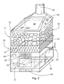
- Figures 1 and 2 show the fireplace according to the invention, using a single-firing sauna stove as an example.
- the fireplace includes a firebox 10, for burning a solid fuel and creating combustion gases. Firewood is usually used as the fuel.
- the fireplace includes a heat store 11 for storing the heat of the combustion gases in the fireplace.
- the heat store 11 is formed of stove stones 12.
- the fireplace further includes a pre-heat store 13, which is fitted between the firebox 10 and the heat store 11 in the direction of flow of the combustion gases.
- the pre-heat store is formed of a metal honeycomb 14, the heat-storage capacity of which is greater than that of the heat store 11.
- the thermal energy of the hot combustion gases is bound to the pre-heat store as efficiently as possible, from where the heat is then released to the heat store.
- the thermal efficiency improves substantially, thus reducing carbon-dioxide emissions, as the amount of fuel required is reduced.
- the energy contained in the fuel is exploited more efficiently than previously.
- more heat is obtained from the same amount of fuel.
- the same heat is obtained using a small amount of fuel than previously.
- the example sauna stove is square and has dimensions of 450 mm x 450 mm.
- the height of the stove to the upper surface of the stove stones is 800 mm.
- Beneath the firebox 10 is a grate 15, which is wide enough and long enough to provide a sufficient amount of oxygen for combustion.
- Beneath the grate 15 is an ash box 16.
- the volume of the firebox is essentially as large or larger than the volume of the solid fuel required to charge the fireplace.
- the amount of firewood required to heat the fireplace will easily fit at one time into the firebox.
- the firebox is 300-mm wide and high, and 450-mm deep.
- at the edges of the firebox there are side plates 17 restricting the width of the combustion chamber, which prevent the firewood from spreading.
- Air can flow from outside the side plates and beneath the grate to under and to the side of the firewood. Air can also flow to above the firewood, to ensure the availability of the oxygen required for the combustion of the hydrocarbons vaporized from the firewood.
- the spacious firebox permits efficient combustion of the fuel.
- the bottom surface area of the firebox 10 is preferably larger than the surface area of the heat store 11 and the pre-heat store 13.
- the combustion gases spread evenly while at the same time the pre-heat store heats throughout.
- the wall 18 guides the combustion gases into the combustion chamber 19, into which additional air can be led if necessary, guided by a slotted plate 20, in order to regulate the stove's internal air circulation.
- the damper (not shown) is closed during sauna bathing.
- the stove includes shut-off means 21 for closing the flow connection from the firebox 10 to the combustion chamber 19.
- the fireplace includes a bypass duct 22, starting from the firebox 10 and arranged to bypass the heat store 11 and the pre-heat store 13.
- the bypass duct 22 is open, the shut-off means 21 being closed.
- the shut-off means 21 close the flow of combustion gases to the bypass duct 22 and allow the combustion gases to enter the pre-heat store 13 through the combustion chamber 19 and from there to the heat store 11 and through the upper flap 26 to the flue 23.
- the steam hatch 24 of the sauna stove is closed during the heating stage. Once there are only embers left in the firebox, the duct running through the stove is closed and at the same time the bypass duct from the firebox to the flue is opened. The embers can then burn completely with practically no cooling effect on heat store. At the same time, bathing can be started immediately, without the danger of carbon monoxide spreading into the sauna rooms.
- the shut-off means 21 are turned to the position, in which they close the flow of combustion gases to the combustion chamber 19 and at the same time open the flow to the bypass duct 22.
- the stove is now ready for bathing. Initially during bathing, the steam hatch 24 is opened and at the same time the upper flap 26 is closed, which prevents the flow of combustion gases to the flue 23. It takes about half an hour to heating the sauna stove to be ready for bathing.
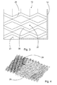
- the structure of the honeycomb can vary in different embodiments.
- the honeycomb 14 is formed of several flow channels 27, thus clearly increasing the heat-transfer surface area.
- the flow channels preferably cross over each other, which makes the mixing of the combustion gases more efficient and helps to improve the thermal efficiency.
- the fireplace according to the invention includes an efficient pre-heat store of small size.
- the pre-heat store is, for example, a honeycomb of corrugated steel or cast-iron sheets stacked on top of each other, or intertwined with each other, which is located immediately after the firebox.
- the honeycomb can be made of a heat-resistant steel sheet web, which is corrugated, for example, at an angle of 70 degrees relates to the longitudinal direction of the web.
- each flow channel 27 is delimited by one or more sheet-like profile pieces 28, to create a good ratio between the flow cross-sectional area and the heat-storing mass.
- Figure 3 shows part of four cast-iron profile pieces 28, which delimit several flow channels 27.
- the honeycomb can also be made from web-shaped cast profile pieces.
- the profile pieces are set opposite each other, in such a way that the ridge corners of the corrugations run in opposite directions. This creates a structure, in which there is a set of channels that cross over each other.
- Figure 4 shows two profile pieces 28 on top of each other, the ridge corners of which run in different directions.
- the profile pieces can be surfaced with, for example, an oxidizing catalyst.
- the honeycomb will then act as a catalyser, which will further significantly reduce the amount of toxic emissions, such as carbon monoxide and hydrocarbons.
- the firebox should be large enough for the amount of wood needed for heating to fit into it at one time. It is also essential to ensure that a sufficient amount of oxygen for combustion is available in the combustion chamber, so that the hydrocarbons vaporized from the firewood can burn properly. This further raises the temperature of the combustion gases, which is essential in order to minimize the hydrocarbon and carbon-monoxide emissions. Due to the space restrictions imposed on sauna stoves, the delay time in the combustion chamber of the combustion gases is short, being in the order of 0,2 seconds. In this case, complete combustion requires a temperature of more than 800°C. To achieve a sufficient temperature, the combustion chamber can, if necessary, be insulated on the inside with heat-resistant insulation, for example, a rock-wool insulation. The insulation also reduces the temperature of the outer surface of the fireplace.
- Efficient combustion reduces hydrocarbon, carbon-monoxide, and particulate emissions.
- the fireplace according to the invention also reduces carbon-dioxide emissions by improving the thermal efficiency of the fireplace by means of a pre-heat store and bypass flow.
- substantially less firewood is needed to heat the fireplace.
- clearly more rapid heating than previously is achieved as an additional advantage.
- the fireplace according to the invention there is a pre-heat store of corrugated steel plates stacked on top of each other, or intertwined with each other, immediately after the firebox.
- a sufficient combustion chamber is arranged before the pre-heat store.
- the flow, and at the same time also the temperature distribution, in the pre-heat store will then equalize. This will improve the efficiency of the pre-heat store and reduce the pressure loss caused by the honeycomb.
- the flow velocity will be greatest in the centre of the flow channel and will diminish rapidly down to zero at the surface of the wall.
- a so-called stationary boundary layer which forms an insulation reducing heat transfer, is also known.
- the flow channels cross over each other and, due to this, each flow channel continually narrows and widens. This prevents a stationary boundary layer from forming and substantially improves the transfer of heat from the combustion gases to the pre-heat store.
- the relative differences of different shapes of flow channel are depicted by the so-called Nusselt number (Nu).
- Nusselt number can be used to depict the heat transfer of a surface relative to a situation, in which only thermal conduction occurs.
- the Nusselt number for a square-shaped flow channel is about 3,0, when the flow velocity is 2 m/s.
- the Nusselt number for a mixing flow channel according to the invention is about 12. In other words, heat is transferred to the heat store four times more efficiently, compared to a square-shaped flow channel.
- the above example compares precisely structured structures, in which the flow distributions are relatively even.
- the size of the flow channels between the stove stones varies very greatly.
- the combustion gases then flow through the path of least resistance.
- the flow resistance is proportional to the square of the hydraulic diameter of the opening, i.e. to the cross-sectional area of the opening.
- the stove stones heat unevenly.
- the heat-transfer surface area is also an important factor.
- the transfer of heat is directly proportional to the heat-transfer surface area.
- this surface area is large, compared, for example, to heat-storing stoves. It can be typically 0,05 - 1,5 m 2 for each storage cubic decimetre. This is much more than in stove stones and the walls of heat-storing stoves, which are typically 0,005 - 0,05 m 2 /dm 3 .
- the thermal conductivity of the stones used in stoves is about 6,0 - 6,5 W/mK.
- the thermal conductivity of cast iron is about 40 - 45 W/mK. In other words, the thermal conductivity of cast iron is 6 - 7 times that of stone.
- the transfer of heat is proportional to the temperature difference of the gas and the heat-transfer surface. As heat transfers efficiently from the surface to the interior of the store material, the temperature difference remains as great as possible.
- the heat can be utilized for the continuous heating during bathing of the stove stones above the pre-heat store in the stove. In open fireplaces, the heat is used to heat circulating air or the storage stones.
- One advantage of using a metal honeycomb pre-heat store is its ability to collect on its surface the soot arising during combustion, due to the mixing flow and thermophoresis. The soot adhering to the flow channels burns off, once the temperature of the surface reaches 600°C.
- the advantages of stones, bricks, or other ceramic heat-storage materials are a cheap price, a good heat-storage capacity (about 1 kJ/khK), and, on the other hand, a relatively poor thermal conductivity and transfer ability compared to a metal construction.
- two different types of heat store are surprisingly combined, thus combining the advantages of both - the efficient heat-transfer ability of a metal pre-heat store and the large storage capacity and slow heat release of a ceramic heat store.
- the sauna stove according to the invention is also advantageously low, so that it also heats the lower parts of the sauna room.
- the amount of wood required to heat a sauna stove is, according to the accompanying calculation, as follows:
- a firebox-full (3,7 kg) of dry wood can heat the stove to bathing condition.
- 11,5 litres of water can be used to make steam.
- the sauna room will be ready for bathing in about half an hour, whereas in known single-firing sauna stoves the heating will take from one to two hours.
- only one-fifth of the firewood required for known stoves will be used. Rapid combustion can be ensured by using pieces of firewood that are smaller and drier than usual.
- the size of the firewood can be, for example, 4 x 4 x 35 cm 3 , in which case the combustion surface area of the firewood will be large.
- the temperature of the flame will then be high, which will further promote the complete combustion of the combustion gases.
- a new type of moveable combustion box which is formed of a grate equipped with sides, can be used as an alternative to a traditional firebox.
- the combustion box is pulled out of the stove's firebox along slider rails and the firewood and kindling are loaded into the combustion box. After this, the firewood is lit and the combustion box is pushed back into place. Ignition can be performed simultaneously from the side and the top.
- the lower part of the combustion box acts as a grate, in which there are transverse fins next to vertical supports, thanks to which a sufficient gap remains between the surface of the grate and the wood to ensure good air circulation.
- the stove stones forming the heat store are laid on top of the pre-heat store.
- the lower metal pre-heat store will be considerably hotter than the upper heat store. When bathing, this will mean a soft discharge of steam, because the stove stones forming the heat store will not be too hot. On the other hand, the stove stones will remain suitably warm for a long time, because the stove stones cooled by the water will receive additional energy from the hot metal pre-heat store.
Landscapes
- Health & Medical Sciences (AREA)
- Public Health (AREA)
- Engineering & Computer Science (AREA)
- Animal Behavior & Ethology (AREA)
- Combustion & Propulsion (AREA)
- Epidemiology (AREA)
- Pain & Pain Management (AREA)
- Physical Education & Sports Medicine (AREA)
- Rehabilitation Therapy (AREA)
- Life Sciences & Earth Sciences (AREA)
- Chemical & Material Sciences (AREA)
- General Health & Medical Sciences (AREA)
- Veterinary Medicine (AREA)
- General Engineering & Computer Science (AREA)
- Mechanical Engineering (AREA)
- Solid-Fuel Combustion (AREA)
Applications Claiming Priority (1)
| Application Number | Priority Date | Filing Date | Title |
|---|---|---|---|
| FI20085260A FI119891B (fi) | 2008-03-31 | 2008-03-31 | Tulisija |
Publications (1)
| Publication Number | Publication Date |
|---|---|
| EP2107315A2 true EP2107315A2 (de) | 2009-10-07 |
Family
ID=39269552
Family Applications (1)
| Application Number | Title | Priority Date | Filing Date |
|---|---|---|---|
| EP09155998A Withdrawn EP2107315A2 (de) | 2008-03-31 | 2009-03-24 | Kamin |
Country Status (2)
| Country | Link |
|---|---|
| EP (1) | EP2107315A2 (de) |
| FI (1) | FI119891B (de) |
Cited By (21)
| Publication number | Priority date | Publication date | Assignee | Title |
|---|---|---|---|---|
| RU2470230C1 (ru) * | 2011-07-13 | 2012-12-20 | Общество с ограниченной ответственностью Завод "Ферингер и К" | Способ получения пара и устройство для его реализации |
| RU2472071C1 (ru) * | 2011-07-13 | 2013-01-10 | Общество с ограниченной ответственностью Завод "Ферингер и К" | Печь |
| RU2490551C2 (ru) * | 2011-03-15 | 2013-08-20 | Общество с ограниченной ответственностью Завод "Ферингер и К" | Печь |
| RU2490548C2 (ru) * | 2011-03-15 | 2013-08-20 | Общество с ограниченной ответственностью Завод "Ферингер и К" | Дымовая труба |
| RU2490550C2 (ru) * | 2011-03-15 | 2013-08-20 | Общество с ограниченной ответственностью Завод "Ферингер и К" | Способ подачи и нагрева пара |
| RU2520206C2 (ru) * | 2012-07-20 | 2014-06-20 | Общество с ограниченной ответственностью Завод "Ферингер и К" | Способ получения пара и устройство для его реализации |
| JP2015096097A (ja) * | 2013-11-15 | 2015-05-21 | 日精オーバル株式会社 | サウナ室用蒸気発生装置 |
| RU2562647C1 (ru) * | 2014-11-13 | 2015-09-10 | Общество с ограниченной ответственностью Завод "Ферингер и К" | Способ получения пара |
| RU2603447C2 (ru) * | 2014-12-30 | 2016-11-27 | Общество с ограниченной ответственностью Завод "Ферингер и К" | Парогенератор ферингера для банных печей |
| RU2603448C2 (ru) * | 2014-12-30 | 2016-11-27 | Общество с ограниченной ответственностью Завод "Ферингер и К" | Парогенератор ферингера для банных печей |
| RU190614U1 (ru) * | 2019-03-25 | 2019-07-04 | Денис Эдуардович Хисамов | Паровая пушка |
| RU2718846C1 (ru) * | 2019-08-05 | 2020-04-14 | Общество с ограниченной ответственностью "Техно Лит" | Банная печь и способ нагрева банной печи |
| RU2718845C1 (ru) * | 2019-08-05 | 2020-04-14 | Общество с ограниченной ответственностью "Техно Лит" | Банная печь и способ нагрева банной печи |
| RU2719686C1 (ru) * | 2019-08-05 | 2020-04-21 | Общество с ограниченной ответственностью "Техно Лит" | Банная печь и способ нагрева банной печи |
| RU201371U1 (ru) * | 2020-08-19 | 2020-12-11 | Рафис Канафейевич Билалов | Печь банная |
| RU202564U1 (ru) * | 2020-11-10 | 2021-02-25 | Максим Дмитриевич Правда | Банная печь |
| RU209278U1 (ru) * | 2021-10-27 | 2022-03-11 | Общество с ограниченной ответственностью "ФОБАЗ" | Парогенератор встраиваемый для банной печи |
| RU209373U1 (ru) * | 2021-11-17 | 2022-03-15 | Сергей Александрович Орлов | Банная печь |
| RU210741U1 (ru) * | 2021-12-23 | 2022-04-29 | Общество с ограниченной ответственностью "ФОБАЗ" | Печь банная с закрытой каменкой |
| RU212345U1 (ru) * | 2021-12-21 | 2022-07-18 | Общество с ограниченной ответственностью "ФОБАЗ" | Парогенератор для банной печи |
| EE01632U1 (et) * | 2023-06-16 | 2024-05-15 | S-Trading OÜ | Süsteem suitsu juhtimiseks sauna leiliruumi |
Families Citing this family (2)
| Publication number | Priority date | Publication date | Assignee | Title |
|---|---|---|---|---|
| RU2544926C1 (ru) * | 2014-01-21 | 2015-03-20 | Индивидуальный Предприниматель Бессонов Константин Евгеньевич | Парообразователь для бани |
| CN120917274A (zh) * | 2023-05-24 | 2025-11-07 | 米卡·塔皮奥·雷约宁 | 壁炉 |
-
2008
- 2008-03-31 FI FI20085260A patent/FI119891B/fi not_active IP Right Cessation
-
2009
- 2009-03-24 EP EP09155998A patent/EP2107315A2/de not_active Withdrawn
Cited By (26)
| Publication number | Priority date | Publication date | Assignee | Title |
|---|---|---|---|---|
| RU2490551C2 (ru) * | 2011-03-15 | 2013-08-20 | Общество с ограниченной ответственностью Завод "Ферингер и К" | Печь |
| RU2490548C2 (ru) * | 2011-03-15 | 2013-08-20 | Общество с ограниченной ответственностью Завод "Ферингер и К" | Дымовая труба |
| RU2490550C2 (ru) * | 2011-03-15 | 2013-08-20 | Общество с ограниченной ответственностью Завод "Ферингер и К" | Способ подачи и нагрева пара |
| RU2470230C1 (ru) * | 2011-07-13 | 2012-12-20 | Общество с ограниченной ответственностью Завод "Ферингер и К" | Способ получения пара и устройство для его реализации |
| RU2472071C1 (ru) * | 2011-07-13 | 2013-01-10 | Общество с ограниченной ответственностью Завод "Ферингер и К" | Печь |
| RU2520206C2 (ru) * | 2012-07-20 | 2014-06-20 | Общество с ограниченной ответственностью Завод "Ферингер и К" | Способ получения пара и устройство для его реализации |
| JP2015096097A (ja) * | 2013-11-15 | 2015-05-21 | 日精オーバル株式会社 | サウナ室用蒸気発生装置 |
| RU2562647C1 (ru) * | 2014-11-13 | 2015-09-10 | Общество с ограниченной ответственностью Завод "Ферингер и К" | Способ получения пара |
| RU2603447C2 (ru) * | 2014-12-30 | 2016-11-27 | Общество с ограниченной ответственностью Завод "Ферингер и К" | Парогенератор ферингера для банных печей |
| RU2603448C2 (ru) * | 2014-12-30 | 2016-11-27 | Общество с ограниченной ответственностью Завод "Ферингер и К" | Парогенератор ферингера для банных печей |
| RU190614U1 (ru) * | 2019-03-25 | 2019-07-04 | Денис Эдуардович Хисамов | Паровая пушка |
| RU2718845C1 (ru) * | 2019-08-05 | 2020-04-14 | Общество с ограниченной ответственностью "Техно Лит" | Банная печь и способ нагрева банной печи |
| RU2718846C1 (ru) * | 2019-08-05 | 2020-04-14 | Общество с ограниченной ответственностью "Техно Лит" | Банная печь и способ нагрева банной печи |
| RU2719686C1 (ru) * | 2019-08-05 | 2020-04-21 | Общество с ограниченной ответственностью "Техно Лит" | Банная печь и способ нагрева банной печи |
| RU201371U1 (ru) * | 2020-08-19 | 2020-12-11 | Рафис Канафейевич Билалов | Печь банная |
| RU202564U1 (ru) * | 2020-11-10 | 2021-02-25 | Максим Дмитриевич Правда | Банная печь |
| RU2780431C1 (ru) * | 2021-10-25 | 2022-09-23 | Дмитрий Николаевич Зайцев | Банная печь |
| RU209278U1 (ru) * | 2021-10-27 | 2022-03-11 | Общество с ограниченной ответственностью "ФОБАЗ" | Парогенератор встраиваемый для банной печи |
| RU209373U1 (ru) * | 2021-11-17 | 2022-03-15 | Сергей Александрович Орлов | Банная печь |
| RU212345U1 (ru) * | 2021-12-21 | 2022-07-18 | Общество с ограниченной ответственностью "ФОБАЗ" | Парогенератор для банной печи |
| RU210741U1 (ru) * | 2021-12-23 | 2022-04-29 | Общество с ограниченной ответственностью "ФОБАЗ" | Печь банная с закрытой каменкой |
| RU213031U1 (ru) * | 2022-05-05 | 2022-08-22 | Общество с ограниченной ответственностью "ФОБАЗ" | Печь банная с закрытой каменкой |
| RU214234U1 (ru) * | 2022-08-23 | 2022-10-17 | Александр Михайлович Анисимов | Банная печь-каменка |
| RU2815215C1 (ru) * | 2023-02-09 | 2024-03-12 | Анатолий Михайлович Денисов | Банная печь с кассетой |
| EE01632U1 (et) * | 2023-06-16 | 2024-05-15 | S-Trading OÜ | Süsteem suitsu juhtimiseks sauna leiliruumi |
| RU2852181C1 (ru) * | 2025-03-31 | 2025-12-04 | Вадим Сергеевич Рыжов | Парогенератор для банной печи |
Also Published As
| Publication number | Publication date |
|---|---|
| FI20085260A0 (fi) | 2008-03-31 |
| FI119891B (fi) | 2009-04-30 |
Similar Documents
| Publication | Publication Date | Title |
|---|---|---|
| EP2107315A2 (de) | Kamin | |
| US4180052A (en) | Furnace fireplace apparatus having separate combustion and heating air systems and settling chambers for particulate matter | |
| RU153204U1 (ru) | Котел отопительный | |
| US10627112B2 (en) | Combustion apparatus | |
| US4292933A (en) | Furnace | |
| RU2660987C1 (ru) | Пиролизный котел-утилизатор | |
| CN201255435Y (zh) | 组合型采暖锅炉 | |
| US4299178A (en) | Furnace and heat storage assembly | |
| RU2551183C2 (ru) | Отопительное устройство | |
| RU2610411C2 (ru) | Отопительное устройство | |
| KR101577813B1 (ko) | 벽난로와 구들난방을 겸하는 난방장치 | |
| RU2743867C1 (ru) | Твёрдотопливный котёл длительного горения | |
| RU2763984C1 (ru) | Отопительная печь длительного горения | |
| US20080035137A1 (en) | Combustion apparatus | |
| RU2445550C1 (ru) | Отопительное устройство | |
| EP1376014B1 (de) | Ofen nach Art eines Kamins | |
| RU121039U1 (ru) | Водогрейный твердотопливный котел-плита | |
| RU2282790C2 (ru) | Печь отопительно-варочная | |
| RU2350845C1 (ru) | Печь | |
| RU2818071C2 (ru) | Твердотопливная печь-плита | |
| RU2803764C1 (ru) | Печь длительного горения | |
| RU2818956C2 (ru) | Отопительное устройство | |
| RU38500U1 (ru) | Камин | |
| RU2780178C1 (ru) | Банная печь | |
| RU224928U1 (ru) | Отопительное устройство |
Legal Events
| Date | Code | Title | Description |
|---|---|---|---|
| PUAI | Public reference made under article 153(3) epc to a published international application that has entered the european phase |
Free format text: ORIGINAL CODE: 0009012 |
|
| AK | Designated contracting states |
Kind code of ref document: A2 Designated state(s): AT BE BG CH CY CZ DE DK EE ES FI FR GB GR HR HU IE IS IT LI LT LU LV MC MK MT NL NO PL PT RO SE SI SK TR |
|
| AX | Request for extension of the european patent |
Extension state: AL BA RS |
|
| STAA | Information on the status of an ep patent application or granted ep patent |
Free format text: STATUS: THE APPLICATION IS DEEMED TO BE WITHDRAWN |
|
| 18D | Application deemed to be withdrawn |
Effective date: 20121002 |