EP2329190B1 - Procédé pour générer une combustion au moyen d'un ensemble brûleur - Google Patents
Procédé pour générer une combustion au moyen d'un ensemble brûleur Download PDFInfo
- Publication number
- EP2329190B1 EP2329190B1 EP09809342.0A EP09809342A EP2329190B1 EP 2329190 B1 EP2329190 B1 EP 2329190B1 EP 09809342 A EP09809342 A EP 09809342A EP 2329190 B1 EP2329190 B1 EP 2329190B1
- Authority
- EP
- European Patent Office
- Prior art keywords
- oxidant
- fuel
- passageway
- supply means
- phase
- Prior art date
- Legal status (The legal status is an assumption and is not a legal conclusion. Google has not performed a legal analysis and makes no representation as to the accuracy of the status listed.)
- Not-in-force
Links
- 238000000034 method Methods 0.000 title claims description 59
- 238000002485 combustion reaction Methods 0.000 title claims description 32
- 239000007800 oxidant agent Substances 0.000 claims description 386
- 230000001590 oxidative effect Effects 0.000 claims description 360
- 239000000446 fuel Substances 0.000 claims description 146
- QVGXLLKOCUKJST-UHFFFAOYSA-N atomic oxygen Chemical compound [O] QVGXLLKOCUKJST-UHFFFAOYSA-N 0.000 claims description 65
- 239000001301 oxygen Substances 0.000 claims description 65
- 229910052760 oxygen Inorganic materials 0.000 claims description 65
- 238000002844 melting Methods 0.000 claims description 29
- 230000008018 melting Effects 0.000 claims description 28
- 230000008569 process Effects 0.000 claims description 20
- 239000004411 aluminium Substances 0.000 claims description 15
- XAGFODPZIPBFFR-UHFFFAOYSA-N aluminium Chemical group [Al] XAGFODPZIPBFFR-UHFFFAOYSA-N 0.000 claims description 15
- 229910052782 aluminium Inorganic materials 0.000 claims description 15
- 230000000712 assembly Effects 0.000 claims description 15
- 238000000429 assembly Methods 0.000 claims description 15
- 239000000203 mixture Substances 0.000 claims description 11
- 238000010309 melting process Methods 0.000 claims description 10
- VNWKTOKETHGBQD-UHFFFAOYSA-N methane Chemical compound C VNWKTOKETHGBQD-UHFFFAOYSA-N 0.000 claims description 8
- 238000003723 Smelting Methods 0.000 claims description 7
- 238000002156 mixing Methods 0.000 claims description 6
- 239000004215 Carbon black (E152) Substances 0.000 claims description 4
- 238000010438 heat treatment Methods 0.000 claims description 4
- 229930195733 hydrocarbon Natural products 0.000 claims description 4
- 150000002430 hydrocarbons Chemical class 0.000 claims description 4
- 239000003345 natural gas Substances 0.000 claims description 3
- 239000007787 solid Substances 0.000 claims description 3
- 239000010763 heavy fuel oil Substances 0.000 claims description 2
- 238000010312 secondary melting process Methods 0.000 claims description 2
- MWUXSHHQAYIFBG-UHFFFAOYSA-N nitrogen oxide Inorganic materials O=[N] MWUXSHHQAYIFBG-UHFFFAOYSA-N 0.000 description 17
- 238000002347 injection Methods 0.000 description 11
- 239000007924 injection Substances 0.000 description 11
- 239000007788 liquid Substances 0.000 description 7
- 239000000463 material Substances 0.000 description 7
- IJGRMHOSHXDMSA-UHFFFAOYSA-N Atomic nitrogen Chemical compound N#N IJGRMHOSHXDMSA-UHFFFAOYSA-N 0.000 description 6
- 239000007789 gas Substances 0.000 description 5
- 239000012768 molten material Substances 0.000 description 5
- 230000003647 oxidation Effects 0.000 description 5
- 238000007254 oxidation reaction Methods 0.000 description 5
- 239000002994 raw material Substances 0.000 description 5
- 230000009467 reduction Effects 0.000 description 5
- 239000012530 fluid Substances 0.000 description 4
- 229910052751 metal Inorganic materials 0.000 description 4
- 239000002184 metal Substances 0.000 description 4
- 239000004449 solid propellant Substances 0.000 description 4
- 238000012546 transfer Methods 0.000 description 4
- MYMOFIZGZYHOMD-UHFFFAOYSA-N Dioxygen Chemical compound O=O MYMOFIZGZYHOMD-UHFFFAOYSA-N 0.000 description 3
- 230000009286 beneficial effect Effects 0.000 description 3
- 230000008901 benefit Effects 0.000 description 3
- 230000015572 biosynthetic process Effects 0.000 description 3
- 238000005265 energy consumption Methods 0.000 description 3
- 229910052757 nitrogen Inorganic materials 0.000 description 3
- ATUOYWHBWRKTHZ-UHFFFAOYSA-N Propane Chemical compound CCC ATUOYWHBWRKTHZ-UHFFFAOYSA-N 0.000 description 2
- PNEYBMLMFCGWSK-UHFFFAOYSA-N aluminium oxide Inorganic materials [O-2].[O-2].[O-2].[Al+3].[Al+3] PNEYBMLMFCGWSK-UHFFFAOYSA-N 0.000 description 2
- 230000008859 change Effects 0.000 description 2
- 238000013461 design Methods 0.000 description 2
- 238000009826 distribution Methods 0.000 description 2
- 239000002737 fuel gas Substances 0.000 description 2
- 230000006872 improvement Effects 0.000 description 2
- 238000012423 maintenance Methods 0.000 description 2
- 238000004519 manufacturing process Methods 0.000 description 2
- 239000003921 oil Substances 0.000 description 2
- 238000004886 process control Methods 0.000 description 2
- 230000000750 progressive effect Effects 0.000 description 2
- 238000007670 refining Methods 0.000 description 2
- 239000011819 refractory material Substances 0.000 description 2
- 238000010079 rubber tapping Methods 0.000 description 2
- 230000006641 stabilisation Effects 0.000 description 2
- 239000003570 air Substances 0.000 description 1
- 238000006375 batch glass melting process Methods 0.000 description 1
- 238000005266 casting Methods 0.000 description 1
- 239000000919 ceramic Substances 0.000 description 1
- 230000003247 decreasing effect Effects 0.000 description 1
- 238000001514 detection method Methods 0.000 description 1
- -1 dirt Chemical class 0.000 description 1
- 239000003344 environmental pollutant Substances 0.000 description 1
- 239000003517 fume Substances 0.000 description 1
- 239000011521 glass Substances 0.000 description 1
- 238000000265 homogenisation Methods 0.000 description 1
- 239000012535 impurity Substances 0.000 description 1
- 238000009434 installation Methods 0.000 description 1
- 239000004922 lacquer Substances 0.000 description 1
- 150000002739 metals Chemical class 0.000 description 1
- 239000003973 paint Substances 0.000 description 1
- 231100000719 pollutant Toxicity 0.000 description 1
- 238000012545 processing Methods 0.000 description 1
- 239000001294 propane Substances 0.000 description 1
- 230000005855 radiation Effects 0.000 description 1
- 238000004064 recycling Methods 0.000 description 1
- 150000003839 salts Chemical class 0.000 description 1
- 239000003923 scrap metal Substances 0.000 description 1
- 230000035939 shock Effects 0.000 description 1
- 230000002269 spontaneous effect Effects 0.000 description 1
- 230000008646 thermal stress Effects 0.000 description 1
Images


Classifications
-
- F—MECHANICAL ENGINEERING; LIGHTING; HEATING; WEAPONS; BLASTING
- F23—COMBUSTION APPARATUS; COMBUSTION PROCESSES
- F23D—BURNERS
- F23D14/00—Burners for combustion of a gas, e.g. of a gas stored under pressure as a liquid
- F23D14/20—Non-premix gas burners, i.e. in which gaseous fuel is mixed with combustion air on arrival at the combustion zone
- F23D14/22—Non-premix gas burners, i.e. in which gaseous fuel is mixed with combustion air on arrival at the combustion zone with separate air and gas feed ducts, e.g. with ducts running parallel or crossing each other
-
- F—MECHANICAL ENGINEERING; LIGHTING; HEATING; WEAPONS; BLASTING
- F23—COMBUSTION APPARATUS; COMBUSTION PROCESSES
- F23D—BURNERS
- F23D14/00—Burners for combustion of a gas, e.g. of a gas stored under pressure as a liquid
- F23D14/32—Burners for combustion of a gas, e.g. of a gas stored under pressure as a liquid using a mixture of gaseous fuel and pure oxygen or oxygen-enriched air
-
- F—MECHANICAL ENGINEERING; LIGHTING; HEATING; WEAPONS; BLASTING
- F23—COMBUSTION APPARATUS; COMBUSTION PROCESSES
- F23D—BURNERS
- F23D2900/00—Special features of, or arrangements for burners using fluid fuels or solid fuels suspended in a carrier gas
- F23D2900/00006—Liquid fuel burners using pure oxygen or O2-enriched air as oxidant
-
- F—MECHANICAL ENGINEERING; LIGHTING; HEATING; WEAPONS; BLASTING
- F23—COMBUSTION APPARATUS; COMBUSTION PROCESSES
- F23D—BURNERS
- F23D2900/00—Special features of, or arrangements for burners using fluid fuels or solid fuels suspended in a carrier gas
- F23D2900/00012—Liquid or gas fuel burners with flames spread over a flat surface, either premix or non-premix type, e.g. "Flächenbrenner"
- F23D2900/00013—Liquid or gas fuel burners with flames spread over a flat surface, either premix or non-premix type, e.g. "Flächenbrenner" with means for spreading the flame in a fan or fishtail shape over a melting bath
-
- F—MECHANICAL ENGINEERING; LIGHTING; HEATING; WEAPONS; BLASTING
- F23—COMBUSTION APPARATUS; COMBUSTION PROCESSES
- F23M—CASINGS, LININGS, WALLS OR DOORS SPECIALLY ADAPTED FOR COMBUSTION CHAMBERS, e.g. FIREBRIDGES; DEVICES FOR DEFLECTING AIR, FLAMES OR COMBUSTION PRODUCTS IN COMBUSTION CHAMBERS; SAFETY ARRANGEMENTS SPECIALLY ADAPTED FOR COMBUSTION APPARATUS; DETAILS OF COMBUSTION CHAMBERS, NOT OTHERWISE PROVIDED FOR
- F23M2900/00—Special features of, or arrangements for combustion chambers
- F23M2900/05021—Wall blocks adapted for burner openings
Definitions
- the present invention relates to methods for generating combustion in furnaces.
- the present invention is particular suited for use in melting processes. It is notably, but not exclusively, suited for use in secondary metal, melting, in particular secondary aluminium melting, and ladle preheating.
- Ladles can be used to carry molten material, in particular molten metal, from the melting furnace to a downstream installation, such as a ladle refining station or a casting station. These ladles are usually preheated to minimize thermal shock and damage to the refractory lining and to reduce temperature drop in the ladle.
- Ladle preheating processes likewise generally comprise several phases or stages:
- the driving forces for cost reductions in melting industries, such as secondary melting industries, are mainly focused along two axes: the reduction of operation costs and the improvement of the process control. Important parameters are:
- a specific parameter for secondary aluminium smelters is the reduction in the formation of dross (the mixture of salt, dirt, aluminium oxides and entrapped metallic aluminium that forms at the surface of the molten aluminium).
- EP-A2-0754912 One family of prior art burner apparatus is disclosed in EP-A2-0754912 , to which the reader is referred for further background information.
- fuel and oxidant are introduced into the furnace through separate cavities in the burner assembly so that the fuel burns with the oxidant in a wide luminous flame, and whereby the combustion of the fuel with the oxidant generates reduced quantities of nitrogen oxides (NOx).
- NOx nitrogen oxides
- Such a prior art burner apparatus provides both good energy efficiency and reduced production of pollutants (NOx).
- One problem with the apparatus described in EP-A2-0754912 is that it is limited to operation with an oxidant in the form of a gas having an oxygen molar concentration of at least 50%. This minimum oxygen requirement limits the flexibility of the apparatus.
- US-A-2001/023053 discloses a burner block assembly which permits oxy-fuel, air-fuel, or an oxygen enriched air-fuel operation without replacing the burner block. However, combustion must be interrupted and the burner inlet arrangement must be modified when switching from oxy-fuel operation to air-fuel operation or to oxygen enriched air-fuel operation.
- US-A-2003/0157450 discloses a specific embodiment of this type of burner block assembly for the combustion of preheated fuel with preheated oxidant.
- the burner block assembly comprises a conduit adapted to convey preheated oxidant and which extends through a plenum adapted to pass ambient temperature fluid into the annular region of the plenum surrounding the preheated oxidant conduit, thereby minimizing thermal stresses on burner parts and net heat loss.
- the ambient temperature fluid passing into the annular region surrounding the preheated oxidant conduit may itself be an oxidant and, in particular, an oxidant of different composition than the preheated oxidant.
- US-A-4547150 discloses a burner assembly with a central fuel injector and a co-axially surrounding oxidant injector, whereby the oxygen content of the oxidant can be varied from no oxygen enrichment (air-fuel combustion) to different levels of oxygen enrichment.
- DE-A-10046569 and US- A-US2002192613 disclose pipe-in-pipe burners for use with two different oxidants with concentric fuel and oxidant injectors and a fuel-oxidant premixing chamber downstream of the fuel injector.
- JP-A-2000146129 discloses a variable rate oxygen enrichment burner with a central fuel gas path and a coaxially surrounding air supply path, and a plurality of tube bodies surrounding the fuel gas path and positioned within the coaxial air supply path.
- a burner assembly also referred to as "burner”
- the present invention provides a method of generating combustion by means of a burner assembly, said burner assembly comprising a refractory block, a fuel supply system and an oxidant supply system.
- the refractory block defines along one plane (hereafter referred to as the 'first plane) at least one fuel passageway extending from a fuel inlet port to a fuel outlet port, and substantially along a separate second plane at least one oxidant passageway extending from an oxidant inlet port to an oxidant outlet port, said first and second planes intersecting along a line that is beyond, i.e. downstream of, said outlet ports.
- the oxidant supply system comprises a pair of separate oxidant supply means: an inner oxidant supply means and an outer oxidant supply means.
- the inner oxidant supply means has an inlet connected in use to a source of a first oxidant.
- the outer oxidant supply means which at least partially surrounds the inner oxidant supply means, has an inlet connected in use to a source of a second oxidant.
- the inner and the outer oxidant supply means extend at least partially into the at least one oxidant passageway, so that the oxidant supply system is configured in use to supply to the outlet port of said at least one oxidant passageway either just one of said first and second oxidants or a combination of both.
- the burner assembly can thus be used to operate with and generate combustion with only the first oxidant, with only the second oxidant or with a combination of the first and the second oxidant.
- the first and second oxidants typically have a different oxygen content (expressed in % vol. oxygen). Consequently, the use of the burner assembly makes it possible to vary the oxygen content of the oxidant supplied by the burner to the combustion process from the oxygen content of the first oxidant to the oxygen content of the second oxidant, and intermediate levels of oxygen content.
- oxidant and “oxidiser” or “oxidizer” are synonymous.
- the term "oxidant” or “oxidiser” refers to the overall “oxidant” as injected by the burner into the combustion zone, whereby said “oxidant” may (a) correspond to the "first oxidant", when only the first oxidant is supplied to the burner, (b) correspond to the “second oxidant", when only the second oxidant is supplied to the burner, or (c) correspond to a combination of the "first” and “second oxidant”, when both first and second oxidant are fed to the burner.
- the second oxidant is an oxidant having an oxygen content below 25% vol., such as air.
- the first oxidant is advantageously an oxygen-rich oxidant having an oxygen content of from 70 to 100% vol., preferably from 90 to 100% vol., and more preferably from 95 to 100% vol.
- the first and/or the second oxidant may be at ambient temperature or preheated. In general, they will either both be at ambient temperature or both preheated.
- the new method offers a possibility of changing over the composition of the oxidant between oxygen and air, or a mix or combination of oxygen and air. It is therefore possible to introduce a portion of air, respectively oxygen into the oxidant in order effectively to change the oxygen content in the oxidant between 21 % vol. (air) and 100 % vol. (pure oxygen) or nearly 100% vol.
- the inner oxidant supply means may stop short of said oxidant outlet port, such that the length of said oxidant passageway that extends between the outlet of said inner oxidant supply means and the orifice of said oxidant outlet port, defines a mixing chamber for pre-mixing said first oxidant with said second oxidant when the oxidant passageway supplies both the first and the second oxidant.
- said inner and outer oxidant supply means are preferably substantially concentric.
- the oxidant supply system of the burner assembly may further comprise means to control the flow rate into said oxidant passageway of at least one, preferably both and most preferably both individually, of said first and second oxidants.
- the burner assembly may comprise a plurality of oxidant passageways and a plurality of fuel passageways, both sets of passageways being spaced apart along their respective planes, said oxidant passageways being positioned above said fuel passageways such that said oxidant meets said fuel along the line of intersection between their respective planes, so as to generate a substantially planar flame front from said line of intersection and directed away from said refractory block.
- the fuel passageway or each said fuel passageway may comprise a fuel injector nozzle having a clearance or passage surrounding it.
- means may be provided to bleed a portion of oxidant from said oxidant supply system into said fuel passageway, and more specifically into said surrounding clearance or passage, so that the bled-off oxidant is injected in the form of a shield surrounding the outside of said fuel injector nozzle, whereby in use said bled-off portion of said bled-off oxidant is injected through the fuel outlet port around the fuel injector nozzle. In this way, flame stability is increased.
- Said oxidant bleed means are typically one or more tubes, pipes or passages fluidly connecting the oxidant supply system with the clearance of the fuel passageway or passageways.
- One or each of said inner and outer oxidant supply means may be configured to supply an oxidant bleed into said fuel supply means, and in particular into a clearance or passage surrounding a fuel injector of said fuel supply means.
- the oxidant bleed means may thus in particular comprise:
- the above-described oxidant bleed means may similarly bleed a combination of the first and second oxidant into the clearance.
- the burner may comprise a plurality of fuel passageways.
- Each of said fuel passageways may be equipped with fuel injectors for the injection of the same fuel or, alternatively two of said fuel passageways may be equipped with fuel injectors configured for the injection of different fuels.
- Said fuel may be a hydrocarbon fuel, such as natural gas or heavy fuel oil.
- the fuel may also be a pulverized solid fuel.
- the method of generating combustion of the present invention generates combustion by means of a burner apparatus according to any one of the embodiments described above, and includes:
- Said method of generating combustion may furthermore include:
- the invention further covers the use of the method of generating combustion in a melting process, and in particular in a secondary melting process such as a secondary aluminium smelting process, and furthermore covers the use of the method of generating combustion in a ladle preheating process.
- line 1 represents the operation of the burner assembly in the method of the invention, using only substantially pure oxygen (first oxidant) as oxidant
- line 2 represents the operation of the burner assembly in the method of the invention using only air (second oxidant) as oxidant
- zone 3 represents the operation of the burner in the method of the invention using a combination of first and second oxidant.
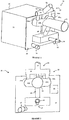
- a burner assembly 10 comprises a refractory block 12 through which are defined a series of passageways.
- the refractory block 12 may be a separate block or assembly of blocks, for example of ceramic. It may be integrated into a wall of a furnace.
- Attached to the back of the refractory block 12 is a mounting bracket 14, a fuel supply system 18 and an oxidant supply system 20.
- the mounting bracket also supports an igniter 16.
- an igniter is optional, and may in particular not be required in furnaces, such as glass-melting furnaces, in which the temperature of the furnace atmosphere is sufficiently high to cause spontaneous ignition of the fuel with the oxidant.
- the igniter 16 is configured to supply a pilot light/ignition flame through an igniter passageway 22 to a pilot jet orifice 24 on a furnace-facing front face 26 of the refractory block 12.
- the mounting bracket further supports a flame detector 50, typically a UV flame detector which is capable of detecting the presence or absence of a flame downstream of the burner through a separate flame detection passageway 52 through the refractory block 12.
- a flame detector 50 typically a UV flame detector which is capable of detecting the presence or absence of a flame downstream of the burner through a separate flame detection passageway 52 through the refractory block 12. The presence of such a flame detector is likewise optional.
- the fuel supply system 18 includes a fuel inlet port 28 for introducing fuel into one or several fuel passageways defined through the refractory block 12.
- Fuel passageway 28B which passes through the refractory block 12 on the plane P1, which lies across the lower half of the refractory block 12 and is represented by A-A in Figure 3 and the associated view of Figure 4 .
- Fuel passageway 28B runs straight through the centre of the refractory block 12 on the plane P1 and has a liquid fuel atomiser 30 positioned along it.
- An inlet for atomising gas for the atomiser 30 is provided in the vicinity of fuel inlet port 28.
- liquid fuel is supplied in atomized form via atomiser 30 centrally aligned along the central passageway 28B and is thus directed into the furnace away from the refractory block 12 along the same plane P1 on which lies the fuel passage 28B.
- FIG. 5 to 8 there are three fuel passageways 28A, 28B, and 28C for gaseous fuel. All three pass through the refractory block 12 on substantially the same horizontal plane P1, which lies across the lower half of the refractory block 12 and is represented by A-A in Figure 5 .
- One of the fuel passageways 28B runs straight through the centre of the refractory block 12 on the plane P1.
- the gaseous fuel is thus directed into the furnace away from the refractory block 12 in such a manner as to form a sheet along the same plane P1 on which lie the fuel passages 28A, 28B, and 28C.
- fuel includes hydrocarbon fuel in liquid or gaseous form. This means, for example, methane, natural gas, propane, atomized oil or the like (either in gaseous or liquid form) at either room temperature (25 DEG C) or in preheated form.
- the "fuel” may also be a pulverized solid fuel.
- Alternative embodiments may comprise several fuel passages with associated atomizers or solid fuel lances, a single fuel passage or a combination of one or more liquid fuel passages with one or more gaseous fuel passages, etc. whereby when several fuel passages are present, these are advantageously situated on the same plane P1.
- an oxidant inlet port 34 is positioned on the mounting bracket 14 above the fuel inlet port 28 and is configured to be connected to an oxidant source (referred to hereafter as “second oxidant source”) for the supply of an oxidant (referred to hereafter as “second oxidant”) for example in the form of air.
- second oxidant source an oxidant source for the supply of an oxidant (referred to hereafter as “second oxidant") for example in the form of air.
- the inlet pipe 34 branches outwards in "Y" form into a pair of reduced diameter branch pipes 40A, 40B that turn back forwards just to the rear side of the mounting bracket 14, through which they pass and lead through a rear face 44 of the refractory block 12 into a pair of oxidant passageways 42A, 42B defined through the refractory block 12 from its rear face 44 to its front face 26.
- the oxidant passageways 42A, 42B pass approximately halfway through the refractory block 12 along respective centrelines co-planar with the centreline of inlet pipe 34 and therefore also on a plane substantially parallel to plane P1 of the fuel passageway 28B, respectively fuel passageways 28A, 28B and 28C.
- the oxidant passageways are angled downwards and exit the front face 26 of the refractory block 12 through respective oxidant outlet ports 46A, 46B.
- the downwards angle of the oxidant outlet port centrelines lies along a plane P2 that intersects the plane P1 of the fuel passageways 28A, 28B, 28C at a point that is spaced apart from the front face 26 of the refractory block 12. This ensures that the oxidant supply will meet the fuel supply at a point that is beyond their respective outlet ports 28A, 28B, 28C, 46A, 46B.
- the plane P2 is represented in the drawings by the drop in the line B-B to the left of the point 60 in Figure 4 . P2 may for example be angled downwards by 5°.
- oxidant bleed pipe 48 which is configured to bleed a portion of oxidant out of oxidant pipe 34 and down to the fuel box 18 (also known as "fuel block” or “fuel supply system”).
- the bled-off oxidant is then used to surround the injection of atomized liquid fuel or gaseous fuel or pulverized solid fuel as it comes out of the fuel passageway 28B, respectively out of the fuel passageways 28A, 28B, 28C, so as to maximise flexibility of operation and flame stability.
- the oxidant supply system further comprises an additional and separate oxidant supply means, configured to supply oxidant from a further oxidant source (referred to hereafter as "first oxidant source”) along the same oxidant supply passageways 42A, 42B as does the second oxidant supply 34, 40A, 40B.
- first oxidant source a further oxidant source
- the apparatus used to deliver the separate first oxidant supply (the oxidant supplied by the first oxidant source being hereafter referred to as "first oxidant" and having a higher oxygen content than the second oxidant) is in the form of an inner oxidant lance 58A, 58B, located one in each oxidant branch pipe 40A, 40B.
- the oxidant lances 58A, 58B are straight and extend further beyond the point 60 in the oxidant passage 42A, 42B at which the oxidant passage 42A, 42B is angled downwards.
- the outlet of each of the oxidant lances 58A, 58B is thus substantially concentric along at least part of the length of their associated oxidant passages 42A, 42B, but, due to the downwards angle, the outlets of the oxidant lances 58A, 58B are higher up in those passageways 42A, 42B. This is best seen with particular reference to Figure 4 .
- Such an embodiment, in which the oxidant lances 58A and 58B are only minimally directed downwards, is particularly useful in furnaces containing a charge, situated below the burner, which is susceptible to unwanted oxidation.
- the burner injects only the second oxidant having a low oxygen content, such as air, into the furnace, said second oxidant is injected downwards towards the charge, thereby increasing convective heat transfer to the charge.
- this second oxidant has only a low oxygen concentration, there is little or no oxidation of the charge.
- both the oxidant passages and the oxidant lances may be directed (downwards) towards the charge in order to increase convective heat transfer.
- the oxidant lances 58A, 58B stop short of their respective outlets of the oxidant passageways 42A, 42B and the region of the oxidant passageways 42A, 42B that lies in between the ends of the oxidant lances 58A, 58B and those outlets defines respective pre-mixing chambers 42C, 42D.
- the pre-mixing chambers 42C, 42D serve to homogenise the mixture between the two separately drawn oxidants prior to discharge, in the event that both oxidant supplies might be in use simultaneously.
- each oxidant lance 58A, 58B is connected to an oxidant supply means 62 that is separated from the oxidant supply that feeds into the large bore oxidant inlet port 34.
- the connection to the separate oxidant supply is in the form of a tubular spigot 64 that joins a log manifold 66 in its centre, the log manifold 66 spanning horizontally over the branch pipes 40A, 40B.
- the oxidant lances 58A, 58B themselves are in the form of L-shaped tubes that drop down from the end regions of the log-manifold 66 and extend into the branch pipes 40A, 40B at the point at which those branch pipes 40A, 40B straighten up and go into the oxidant passageways 42A, 42B. In this manner, the oxidant lances 58A, 58B need only one elbow so as to turn along the oxidant passageways 42A, 42B.
- this narrow bore pipe is configured to bleed a portion of the separate first oxidant supply out of the log manifold down to the fuel box 18.
- the oxidant bled-off by the narrow bore bleed pipe is also used to surround the injection of atomized liquid fuel or of gaseous fuel as it comes out of respectively the fuel passageway 28B or the fuel passageways 28A, 28B, 28C, so as to improve flame stability and operation flexibility.
- the structure of the preferred embodiment ensures that there is always a supply of bled-off oxidant around the gaseous fuel injection for flame stabilisation, regardless of which oxidant supply is being used, either alone or in combination with the other. Flame stabilisation is in this case achieved by injection of some of an oxidant around the fuel injector and the remainder at some distance from the fuel injector.
- the NOx emissions are minimal when the oxidant consists essentially of pure oxygen, but tend to rise as oxygen levels in the oxidant decrease and nitrogen levels correspondingly increase.
- the present invention provides the physical structure for two separate supplies of oxidant into a furnace and enables flexible use of those oxidants, either completely one or the other, or any mixture between the two.
- One oxidant may for example be air and the other oxygen, such that operation can take place from 21% oxygen concentration (air only) through to 100% oxygen or substantially 100% oxygen.
- Aluminium use has increased more than any other metal in recent years and a growth rate greater than that of the other metals is also expected for many years to come.
- a batch aluminium smelting process and in particular a secondary aluminium smelting process may be conducted as follows.
- the smelting process is conducted in a furnace equipped with one or more burner assemblies .
- the first oxidant is an oxygen-rich gas having an oxygen content of at least 70% vol., and preferably at least 90% vol. and more preferably at least 95% vol.
- the second oxidant has an oxygen content of not more than 25% vol. and is preferably air.
- Said process includes the following phases:
- the one or more burner assemblies are operated so that the oxidant consists mainly (i.e. for more than 50% vol. and advantageously for more than 75% by volume) of the first oxidant.
- the main portion (more than 50% vol. and advantageously for more than 75% by volume) of the oxidant is provided by the inner oxidant supply means, the inlet of which is connected to a source of the first oxidant.
- the oxidant consists entirely of the first oxidant.
- the entirety of the oxidant is provided by said inner oxidant supply means supplying the oxygen-rich first oxidant gas.
- the oxygen content of the oxidant is decreased by increasing the portion of the oxidant which consists of the second oxidant (i.e. air). This is achieved by increasing the ratio between (a) the supply (or flow or flow rate) of the second oxidant through the outer oxidant supply means and (b) the supply (or flow or flow rate) of the first oxidant through the inner oxidant supply means.
- This increase can be a stepwise increase or a gradual or progressive increase. Use is made thereto of the means of the burner assembly for controlling the respective flows. A gradual increase is preferable for reasons of flame stability.
- the one or more burner assemblies are operated so that the oxidant consists mainly (i.e. for more than 50% vol. and advantageously for more than 75% by volume) of the second oxidant, i.e. air.
- the main portion (more than 50% vol. and advantageously for more than 75% by volume) of the oxidant is provided by the outer oxidant supply means, the inlet of which is connected to a source of the second oxidant/air.
- the oxidant preferably consists entirely of the second oxidant.
- the entirety of the oxidant is air provided by said outer oxidant supply means supplying the second oxidant which has a relatively low oxygen content, in particular air.
- this combustible matter may act as fuel in the early stages of the melting phase.
- the ratio between, on the one hand, the amount (flow or flow rate) of fuel supplied by the one or more burner assemblies through the one or more fuel outlet ports and, on the other hand, the amount (flow of flow rate) of oxygen supplied as part of the oxidant through the one or more oxidant outlet ports may temporarily be reduced. In this manner the fuel contribution of the raw material is taken into account.
- the temperature rapidly increases at the start of the melting phase and melting occurs more rapidly. Energy efficiency is also increased due to the highly radiative flame and the consequent high radiative energy transfer to the charge.
- the aluminium is in molten form and at high temperature, which results in an increased risk of oxidation and consequent increased risk of loss of material formation of dross.
- the risk of loss of material can be reduced by creating a substantially homogeneous or uniform temperature profile of the atmosphere above the charge along the furnace.
- a reduction in the loss of material during the fining stage is achieved by operating, during the fining stage, the one or more burner assemblies so that the oxidant consists mainly and preferably entirely of air.
- the one or more burner assemblies can advantageously be operated, with air as the oxidant, so as to achieve an essentially homogeneous combustion above the charge and therefore also an essentially homogeneous and uniform temperature profile above the charge along the furnace.
- a ladle preheating process may be conducted as follows: an initial phase with the objective of heating up the ladle vessel to an elevated temperature. During this phase the oxygen content of the oxidiser is chosen to be high in order to increase the energy intensity of the process and consequently reducing the time necessary for the process step.
- a second phase following the initial phase, is the holding phase in which the ladle vessel is maintained at an elevated temperature, allowing an uniform temperature distribution throughout the refractory material. During this second phase, the energy input is reduced in order to only maintain the desired temperature.
- oxygen and air the optimum mixture of oxygen and air can be chosen in order to obtain the lowest possible overall operational costs.
- the one or more burner assemblies are operated so that the oxidant consists mainly (i.e. for more than 50%vol and advantageously for more than 75% by volume) of the first oxidant.
- the main portion (more than 50%vol and advantageously for more than 75% by volume) of the oxidant is provided by the inner oxidant supply means, the inlet of which is connected to a source of the first oxidant.
- the oxidant consists entirely of the first oxidant.
- the entirety of the oxidant is provided by said inner oxidant supply means supplying the oxygen-rich first oxidant gas, thereby accelerating the preheating of the ladle vessel.
- the one or more burner assemblies are operated so that the oxidant consists mainly (i.e. for more than 50% vol. and advantageously for more than 75% by volume) of the second oxidant, i.e. air.
- the main portion (more than 50% vol. and advantageously for more than 75% by volume) of the oxidant is provided by the outer oxidant supply means, the inlet of which is connected to a source of the second oxidant/air.
- the oxidant preferably consists entirely of the second oxidant.
- the entirety of the oxidant is air provided by said outer oxidant supply means supplying the second oxidant which has a relatively low oxygen content, in particular air.
- the present invention therefore allows a user to better adapt the oxidant composition to the cycle requirements, such as for example to furnace load or to the power requirements in the melting cycle.
- the furnace can also be optimized to the instantaneous market price of oxidants and fuel, e.g. 100% oxygen when the fuel is expensive and 100% air when fuel is cheap, or any mixture between the two.
Landscapes
- Engineering & Computer Science (AREA)
- Chemical & Material Sciences (AREA)
- Combustion & Propulsion (AREA)
- Mechanical Engineering (AREA)
- General Engineering & Computer Science (AREA)
Claims (15)
- Procédé de génération de combustion au moyen d'un ensemble de brûleur (10) comprenant un bloc réfractaire (12), un système d'alimentation en combustible (18) et un système d'alimentation en oxydant (20), le bloc réfractaire définissant le long d'un premier plan au moins un passage de combustible (28A, 28B, 28C) s'étendant d'un orifice d'entrée de combustible à un orifice de sortie de combustible et sensiblement le long d'un second plan au moins un passage à oxydant (42A, 42B) s'étendant d'un orifice d'entrée d'oxydant à un orifice de sortie d'oxydant (46A, 46B), lesdits premier et second plans se coupant le long d'une ligne qui se trouve au-delà desdits orifices de sortie, ledit système d'alimentation en oxydant comprenant un moyen intérieur d'alimentation en oxydant ayant une entrée raccordée à une source d'un premier oxydant et un moyen extérieur d'alimentation en oxydant qui entoure au moins en partie le moyen intérieur d'alimentation en oxydant et qui a une entrée raccordée à une source d'un second oxydant, ledit moyen d'alimentation en oxydant intérieur s'étendant au moins en partie dans le au moins un passage à oxydant,
le procédé comprenant :(a) l'alimentation sélective du moyen intérieur d'alimentation en oxydant d'un passage à oxydant (42A, 42B) d'un bloc réfractaire (12) par un premier oxydant, ledit premier oxydant contenant avantageusement au moins 70 % en volume d'oxygène et, de préférence, au moins 90 % en volume et, plus de préférence, au mieux 95 % en volume ;(b) l'alimentation sélective du moyen extérieur concentrique d'alimentation en oxydant du même passage à oxydant par un second oxydant, ledit second oxydant contenant de préférence moins de 25 % d'oxygène, et se présentant avantageusement sous la forme d'air ; et(d) l'acheminement dudit oxydant ou desdits oxydants vers un combustible pour le soumettre à une combustion avec celui-ci en aval de l'ensemble de brûleurs (10) ;le procédé étant caractérisé en ce que :• le moyen extérieur d'alimentation en oxydant s'étend au moins en partie dans le au moins un passage à oxydant ; et• en ce que le système d'alimentation en oxydant est configuré pour alimenter l'orifice de sortie dudit au moins un passage à oxydant, juste l'un desdits premier et second oxydants ou une combinaison des deux ;le procédé comprenant en outre :(c) la variation du rapport entre lesdits premier et second oxydants qui sont fournis auxdits au moins un passage à oxydant entre l'alimentation uniquement du premier oxydant au moyen intérieur d'alimentation en oxydant, l'alimentation uniquement du second oxydant au moyen extérieur concentrique d'alimentation en oxydant et l'alimentation d'une combinaison du premier oxydant au moyen intérieur d'alimentation en oxydant et du second oxydant au moyen extérieur concentrique d'alimentation en oxydant. - Procédé selon la revendication 1, comprenant en outre :(c') l'alimentation d'au moins un passage de combustible (28A, 28B, 28C) par un combustible et l'injection dudit combustible à travers l'orifice de sortie de combustible dudit au moins un passage à combustible (28A, 28B, 28C).
- Procédé selon la revendication 1 ou 2, dans lequel, à l'étape d'acheminement de l'oxydant ou des oxydants, le ou lesdits oxydants est ou sont acheminés vers un combustible pour effectuer une combustion avec celui-ci en aval de l'ensemble de brûleurs, le premier oxydant est acheminé dans une première direction qui forme un premier angle avec le premier plan et le second oxydant est acheminé le long d'une seconde direction formant un second angle avec le premier plan et dans lequel le premier angle est supérieur au second angle.
- Procédé selon l'une quelconque des revendications précédentes, dans lequel ledit moyen intérieur d'alimentation en oxydant (58A, 58B) s'arrête à court dans ledit orifice de sortie d'oxydant (46A, 46B) de sorte que la longueur dudit passage à oxydant (42A, 42B) qui s'étend entre la sortie dudit moyen intérieur d'alimentation en oxydant et l'orifice dudit orifice de sortie d'oxydant, définisse une chambre de mélange (42C, 42D) pour pré-mélanger ledit premier oxydant avec ledit second oxydant.
- Procédé selon l'une quelconque des revendications précédentes, dans lequel le au moins un passage à oxydant (42A, 42B) est positionné au-dessus du au moins un passage de combustible (28A, 28B, 28C) dans le bloc réfractaire (12).
- Procédé selon l'une quelconque des revendications précédentes, dans lequel ledit système d'alimentation en oxydant (20) comprend en outre des moyens commandant le débit dans ledit passage à oxydant d'au moins un, de préférence des deux et, plus de préférence, des deux individuellement parmi ledit premier et ledit second oxydant.
- Procédé selon l'une quelconque des revendications précédentes, comprenant une pluralité de passages à oxydant (42A, 42B) et une pluralité de passages de combustible (28A, 28B, 28C), les deux ensembles de passages étant espacés le long de leurs plans respectifs, lesdits passages à oxydant étant positionnés au-dessus desdits passages de combustible de sorte que ledit oxydant, ou le mélange desdits oxydants le cas échéant rencontre ledit combustible le long de la ligne d'intersection entre leurs plans respectifs de manière à générer une flamme sensiblement plane devant ladite ligne d'intersection et s'écartant dudit bloc réfractaire (12).
- Procédé selon l'une quelconque des revendications précédentes, dans lequel le ou chaque dit passage de combustible (28A, 28B, 28C) comprend une buse d'injecteur de combustible ayant un jeu qui l'entoure et dans lequel des moyens (48, 68) sont prévus qui soufflent une partie d'oxydant dudit système d'alimentation en oxydant (20) dans ledit jeu dudit passage de combustible, ledit moyen de soufflage d'oxydant étant configuré pour souffler son oxydant soufflé sous la forme d'un écran entourant l'extérieur de ladite buse d'injecteur de combustible.
- Procédé selon la revendication 8, dans lequel ledit moyen de soufflage d'oxydant comprend une première liaison (68) entre le moyen intérieur d'alimentation en oxydant et ledit jeu dudit passage de combustible (48A, 48B, 48C) qui souffle une partie du premier oxydant dans ledit passage de combustible lorsque ledit système d'alimentation en oxydant (20) fournit le premier oxydant à l'orifice de sortie (46A, 46B) dudit au moins un passage à oxydant (42A, 42B) et dans lequel ledit moyen de soufflage d'oxydant comprend en outre une seconde liaison (48) entre le moyen extérieur d'alimentation en oxydant et ledit jeu dudit passage de combustible, qui souffle une partie du second oxydant dans ledit jeu dudit passage de combustible lorsque ledit système d'alimentation en oxydant fournit le second oxydant à l'orifice de sortie dudit au moins un passage à oxydant.
- Procédé selon l'une quelconque des revendications précédentes, dans lequel ledit combustible comprend un combustible hydrocarboné, tel que du gaz naturel ou du gaz lourd ou du combustible hydrocarboné solide pulvérisé.
- Utilisation d'un procédé selon l'une quelconque des revendications 1 à 10 dans un procédé de fusion ou un four à fusion.
- Utilisation d'un procédé selon l'une quelconque des revendications 1 à 10 dans un processus de préchauffage de poche de coulée.
- Procédé de fusion d'une charge dans un four en utilisant un procédé selon l'une quelconque des revendications 1 à 10, dans lequel de la chaleur est fournie par les un ou plusieurs ensembles de brûleurs en brûlant du combustible avec un oxydant,
ledit procédé comprenant :• une phase de chargement,• une phase de fusion,• une phase d'affinage et• une phase de décharge,et dans lequel,• au début de la phase de fusion, les un ou plusieurs ensembles de brûleurs (10) sont actionnés de sorte que plus de 50 % en volume, de préférence plus de 75 % en volume et plus de préférence que la totalité de l'oxydant soit le premier oxydant fourni par le moyen intérieur d'alimentation en oxydant, dont l'entrée est raccordée à une source du premier oxydant,• à la fin de la phase de fusion, le rapport entre (a) l'écoulement du second oxydant à travers le moyen extérieur d'alimentation en oxydant et (b) l'écoulement du premier oxydant à travers le moyen intérieur d'alimentation en oxydant est augmenté et,• au cours de la phase d'affinage, les un ou plusieurs ensembles de brûleurs sont actionnés de sorte que plus de 50 % en volume, de préférence plus de 75 % en volume et plus de préférence que la totalité de l'oxydant soit le second oxydant fourni par le moyen extérieur d'alimentation en oxydant, dont l'entrée est raccordée à une source du second oxydant. - Procédé selon la revendication 13, dans lequel ledit procédé est un procédé de fusion secondaire, de préférence un procédé de coulée d'aluminium secondaire.
- Procédé de préchauffage d'une poche de coulée ayant une cuve de poche de coulée utilisant un procédé selon l'une quelconque des revendications 1 à 10, dans lequel de la chaleur est fournie par les un ou plusieurs ensembles de brûleurs en faisant brûler du combustible avec un oxydant, ledit procédé comprenant :• une phase de chauffage initiale,• une phase d'équilibrage de température ultérieure,et dans lequel,• au cours de la phase de chauffage, les un ou plusieurs ensembles de brûleurs (10) sont actionnés de sorte que plus de 50 % en volume, de préférence plus de 75 % en volume et plus de préférence que la totalité de l'oxydant soit le premier oxydant fourni par le moyen intérieur d'alimentation en oxydant, dont l'entrée est raccordée à une source du premier oxydant et• au cours de la phase d'équilibrage de température, les un ou plusieurs ensembles de brûleurs sont actionnés de sorte que plus de 50 % en volume, de préférence plus de 75 % en volume et plus de préférence que la totalité de l'oxydant soit le second oxydant fourni par le moyen extérieur d'alimentation en oxydant, dont l'entrée est raccordée à une source du second oxydant.
Priority Applications (2)
| Application Number | Priority Date | Filing Date | Title |
|---|---|---|---|
| EP09809342.0A EP2329190B1 (fr) | 2008-08-29 | 2009-08-27 | Procédé pour générer une combustion au moyen d'un ensemble brûleur |
| PL09809342T PL2329190T3 (pl) | 2008-08-29 | 2009-08-27 | Sposób generowania spalania z użyciem zespołu palnika |
Applications Claiming Priority (3)
| Application Number | Priority Date | Filing Date | Title |
|---|---|---|---|
| EP08105190 | 2008-08-29 | ||
| PCT/EP2009/061097 WO2010023256A1 (fr) | 2008-08-29 | 2009-08-27 | Procédé pour générer une combustion au moyen d’un ensemble brûleur and ensemble brûleur à cet effet |
| EP09809342.0A EP2329190B1 (fr) | 2008-08-29 | 2009-08-27 | Procédé pour générer une combustion au moyen d'un ensemble brûleur |
Publications (2)
| Publication Number | Publication Date |
|---|---|
| EP2329190A1 EP2329190A1 (fr) | 2011-06-08 |
| EP2329190B1 true EP2329190B1 (fr) | 2018-10-10 |
Family
ID=40456444
Family Applications (1)
| Application Number | Title | Priority Date | Filing Date |
|---|---|---|---|
| EP09809342.0A Not-in-force EP2329190B1 (fr) | 2008-08-29 | 2009-08-27 | Procédé pour générer une combustion au moyen d'un ensemble brûleur |
Country Status (10)
| Country | Link |
|---|---|
| US (1) | US9651248B2 (fr) |
| EP (1) | EP2329190B1 (fr) |
| JP (1) | JP5642679B2 (fr) |
| CN (1) | CN102138040B (fr) |
| BR (1) | BRPI0917907A2 (fr) |
| CA (1) | CA2734955C (fr) |
| ES (1) | ES2698453T3 (fr) |
| PL (1) | PL2329190T3 (fr) |
| RU (1) | RU2474760C2 (fr) |
| WO (1) | WO2010023256A1 (fr) |
Families Citing this family (14)
| Publication number | Priority date | Publication date | Assignee | Title |
|---|---|---|---|---|
| EP2143999A1 (fr) * | 2008-07-08 | 2010-01-13 | L'Air Liquide Société Anonyme pour l'Etude et l'Exploitation des Procédés Georges Claude | Ensemble de brûleur et procédé de combustion |
| US8632621B2 (en) | 2010-07-12 | 2014-01-21 | L'air Liquide, Societe Anonyme Pour L'etude Et L'exploitation Des Procedes Georges Claude | Method for melting a solid charge |
| EP2479492A1 (fr) | 2011-01-21 | 2012-07-25 | Technip France | Brûleur, four |
| WO2013063316A1 (fr) | 2011-10-25 | 2013-05-02 | Daylight Solutions, Inc. | Microscope d'imagerie infrarouge |
| WO2013097165A1 (fr) * | 2011-12-30 | 2013-07-04 | American Air Liquide, Inc. | Procédé de production d'une flamme plate par un brûleur à oxy-combustible solide |
| JP6070323B2 (ja) * | 2013-03-21 | 2017-02-01 | 大陽日酸株式会社 | 燃焼バーナ、バーナ装置、及び原料粉体加熱方法 |
| JP6277261B2 (ja) * | 2014-02-26 | 2018-02-07 | 東芝燃料電池システム株式会社 | バーナー |
| US10520221B2 (en) | 2015-04-06 | 2019-12-31 | Carrier Corporation | Refractory for heating system |
| EP3339730B1 (fr) * | 2016-12-22 | 2021-08-18 | L'air Liquide, Societe Anonyme Pour L'etude Et L'exploitation Des Procedes Georges Claude | Installation et procédé de combustion étagée |
| EP3441670A1 (fr) * | 2017-08-09 | 2019-02-13 | Linde Aktiengesellschaft | Procédé et ensemble brûleur servant à brûler un gaz combustible au moyen d'un oxydant |
| EP3715717B9 (fr) * | 2019-03-26 | 2021-11-24 | L'air Liquide, Societe Anonyme Pour L'etude Et L'exploitation Des Procedes Georges Claude | Procédé de combustion et brûleur pour sa mise en oeuvre |
| JP7525622B2 (ja) | 2020-02-12 | 2024-07-30 | シーラス ヒート テクノロジー カンパニー エルエルシー | 酸素フラットフレームバーナ及びブロックのアセンブリ |
| US11639792B2 (en) * | 2020-06-24 | 2023-05-02 | Rheem Manufacturing Company | Single-piece refractory for a water heating assembly |
| CN112815308B (zh) * | 2020-12-31 | 2021-12-17 | 长沙广钢气体有限公司 | 一种熔炼反射炉用纯氧燃烧装置及燃烧方法 |
Citations (1)
| Publication number | Priority date | Publication date | Assignee | Title |
|---|---|---|---|---|
| DE102004037620A1 (de) * | 2004-08-02 | 2006-02-23 | Air Liquide Deutschland Gmbh | Brennstoff-Sauerstoff-Brenner mit variabler Flammenlänge |
Family Cites Families (12)
| Publication number | Priority date | Publication date | Assignee | Title |
|---|---|---|---|---|
| US4547150A (en) | 1984-05-10 | 1985-10-15 | Midland-Ross Corporation | Control system for oxygen enriched air burner |
| US5302112A (en) | 1993-04-09 | 1994-04-12 | Xothermic, Inc. | Burner apparatus and method of operation thereof |
| US5554022A (en) * | 1994-10-14 | 1996-09-10 | Xothermic, Inc. | Burner apparatus and method |
| DE69632666T2 (de) | 1995-07-17 | 2005-06-09 | L'Air Liquide, S.A. a Directoire et Conseil de Surveillance pour l'Etude et l'Exploitation des Procédés Georges Claude | Verbrennungsverfahren und Vorrichtung dafür mit getrennter Einspritzung von Brennstoff und Oxydationsmittel |
| FR2783595B1 (fr) * | 1998-09-22 | 2000-10-20 | Air Liquide | Procede de chauffage d'un four |
| JP3738141B2 (ja) | 1998-11-10 | 2006-01-25 | 岩谷産業株式会社 | 酸素富化率可変バーナ |
| US6126438A (en) * | 1999-06-23 | 2000-10-03 | American Air Liquide | Preheated fuel and oxidant combustion burner |
| CA2323032A1 (fr) | 1999-10-18 | 2001-04-18 | Air Products And Chemicals, Inc. | Methode et appareil de securite pour la combustion a l'oxygaz a l'aide de la combustion d'un melange air-combustible |
| FR2804497B1 (fr) | 2000-02-01 | 2002-03-29 | Air Liquide | Bruleur aero-oxy-gaz a flamme stabilisee, et bloc-ouvreau equipe d'un tel bruleur |
| DE10046569A1 (de) | 2000-09-19 | 2002-03-28 | Linde Ag | Verfahren und Brenner zum Aluminiumschmelzen |
| FR2823290B1 (fr) * | 2001-04-06 | 2006-08-18 | Air Liquide | Procede de combustion comportant des injections separees de combustible et d oxydant et ensemble bruleur pour la mise en oeuvre de ce procede |
| JP2004115823A (ja) * | 2002-09-24 | 2004-04-15 | Katsuhiko Yamada | 溶鋼の精錬方法 |
-
2009
- 2009-08-27 ES ES09809342T patent/ES2698453T3/es active Active
- 2009-08-27 WO PCT/EP2009/061097 patent/WO2010023256A1/fr active Application Filing
- 2009-08-27 CN CN200980133387.5A patent/CN102138040B/zh not_active Expired - Fee Related
- 2009-08-27 CA CA2734955A patent/CA2734955C/fr not_active Expired - Fee Related
- 2009-08-27 PL PL09809342T patent/PL2329190T3/pl unknown
- 2009-08-27 JP JP2011524387A patent/JP5642679B2/ja not_active Expired - Fee Related
- 2009-08-27 BR BRPI0917907A patent/BRPI0917907A2/pt not_active Application Discontinuation
- 2009-08-27 US US13/061,418 patent/US9651248B2/en not_active Expired - Fee Related
- 2009-08-27 EP EP09809342.0A patent/EP2329190B1/fr not_active Not-in-force
- 2009-08-27 RU RU2011111723/06A patent/RU2474760C2/ru not_active IP Right Cessation
Patent Citations (1)
| Publication number | Priority date | Publication date | Assignee | Title |
|---|---|---|---|---|
| DE102004037620A1 (de) * | 2004-08-02 | 2006-02-23 | Air Liquide Deutschland Gmbh | Brennstoff-Sauerstoff-Brenner mit variabler Flammenlänge |
Also Published As
| Publication number | Publication date |
|---|---|
| RU2011111723A (ru) | 2012-10-10 |
| ES2698453T3 (es) | 2019-02-04 |
| JP5642679B2 (ja) | 2014-12-17 |
| EP2329190A1 (fr) | 2011-06-08 |
| US20110146450A1 (en) | 2011-06-23 |
| CN102138040A (zh) | 2011-07-27 |
| WO2010023256A1 (fr) | 2010-03-04 |
| CN102138040B (zh) | 2014-09-10 |
| US9651248B2 (en) | 2017-05-16 |
| JP2012500962A (ja) | 2012-01-12 |
| PL2329190T3 (pl) | 2019-01-31 |
| CA2734955C (fr) | 2017-04-11 |
| CA2734955A1 (fr) | 2010-03-04 |
| RU2474760C2 (ru) | 2013-02-10 |
| BRPI0917907A2 (pt) | 2015-11-10 |
Similar Documents
| Publication | Publication Date | Title |
|---|---|---|
| EP2329190B1 (fr) | Procédé pour générer une combustion au moyen d'un ensemble brûleur | |
| KR100769098B1 (ko) | 산화제 분사 방법 | |
| AU726896B2 (en) | Combustion process and apparatus therefore containing separate injection of fuel and oxidant streams | |
| CN101415993A (zh) | 氧化燃料和空气燃料燃烧的整合 | |
| US7549858B2 (en) | Combustion with variable oxidant low NOx burner | |
| PL200214B1 (pl) | Sposób spalania w piecu, do którego wtryskuje się oddzielnie co najmniej jedno paliwo i co najmniej jeden utleniacz oraz zespół palnikowy do oddzielnego wtryskiwania | |
| KR101539483B1 (ko) | 버너 조립체 및 연소 방법 | |
| US20120216730A1 (en) | Method of Combusting Particulate Solid Fuel with a Burner | |
| CN111417822B (zh) | 一种能用于固体燃料和气体燃料的氧化剂-多燃料烧嘴 | |
| CN114761730A (zh) | 用于燃料燃烧的燃烧器及其燃烧方法 | |
| CN102459102A (zh) | 通过小炉的氧气燃料燃烧器 | |
| RU2525422C2 (ru) | Способ гомогенизации распределения тепла, а также снижения количества оксидов азота (nox) | |
| US20100239988A1 (en) | Oxygen injection through a roof or crown of a glass furnace | |
| RU2340855C1 (ru) | Способ сжигания углеводородного топлива в вагранке |
Legal Events
| Date | Code | Title | Description |
|---|---|---|---|
| PUAI | Public reference made under article 153(3) epc to a published international application that has entered the european phase |
Free format text: ORIGINAL CODE: 0009012 |
|
| 17P | Request for examination filed |
Effective date: 20110329 |
|
| AK | Designated contracting states |
Kind code of ref document: A1 Designated state(s): AT BE BG CH CY CZ DE DK EE ES FI FR GB GR HR HU IE IS IT LI LT LU LV MC MK MT NL NO PL PT RO SE SI SK SM TR |
|
| AX | Request for extension of the european patent |
Extension state: AL BA RS |
|
| DAX | Request for extension of the european patent (deleted) | ||
| 17Q | First examination report despatched |
Effective date: 20160302 |
|
| STAA | Information on the status of an ep patent application or granted ep patent |
Free format text: STATUS: EXAMINATION IS IN PROGRESS |
|
| GRAP | Despatch of communication of intention to grant a patent |
Free format text: ORIGINAL CODE: EPIDOSNIGR1 |
|
| STAA | Information on the status of an ep patent application or granted ep patent |
Free format text: STATUS: GRANT OF PATENT IS INTENDED |
|
| INTG | Intention to grant announced |
Effective date: 20180321 |
|
| GRAS | Grant fee paid |
Free format text: ORIGINAL CODE: EPIDOSNIGR3 |
|
| GRAA | (expected) grant |
Free format text: ORIGINAL CODE: 0009210 |
|
| STAA | Information on the status of an ep patent application or granted ep patent |
Free format text: STATUS: THE PATENT HAS BEEN GRANTED |
|
| AK | Designated contracting states |
Kind code of ref document: B1 Designated state(s): AT BE BG CH CY CZ DE DK EE ES FI FR GB GR HR HU IE IS IT LI LT LU LV MC MK MT NL NO PL PT RO SE SI SK SM TR |
|
| REG | Reference to a national code |
Ref country code: GB Ref legal event code: FG4D |
|
| REG | Reference to a national code |
Ref country code: CH Ref legal event code: EP Ref country code: AT Ref legal event code: REF Ref document number: 1051677 Country of ref document: AT Kind code of ref document: T Effective date: 20181015 |
|
| REG | Reference to a national code |
Ref country code: IE Ref legal event code: FG4D |
|
| REG | Reference to a national code |
Ref country code: DE Ref legal event code: R096 Ref document number: 602009055029 Country of ref document: DE |
|
| REG | Reference to a national code |
Ref country code: ES Ref legal event code: FG2A Ref document number: 2698453 Country of ref document: ES Kind code of ref document: T3 Effective date: 20190204 |
|
| REG | Reference to a national code |
Ref country code: NL Ref legal event code: MP Effective date: 20181010 |
|
| REG | Reference to a national code |
Ref country code: LT Ref legal event code: MG4D |
|
| REG | Reference to a national code |
Ref country code: AT Ref legal event code: MK05 Ref document number: 1051677 Country of ref document: AT Kind code of ref document: T Effective date: 20181010 |
|
| PG25 | Lapsed in a contracting state [announced via postgrant information from national office to epo] |
Ref country code: NL Free format text: LAPSE BECAUSE OF FAILURE TO SUBMIT A TRANSLATION OF THE DESCRIPTION OR TO PAY THE FEE WITHIN THE PRESCRIBED TIME-LIMIT Effective date: 20181010 |
|
| PG25 | Lapsed in a contracting state [announced via postgrant information from national office to epo] |
Ref country code: AT Free format text: LAPSE BECAUSE OF FAILURE TO SUBMIT A TRANSLATION OF THE DESCRIPTION OR TO PAY THE FEE WITHIN THE PRESCRIBED TIME-LIMIT Effective date: 20181010 Ref country code: HR Free format text: LAPSE BECAUSE OF FAILURE TO SUBMIT A TRANSLATION OF THE DESCRIPTION OR TO PAY THE FEE WITHIN THE PRESCRIBED TIME-LIMIT Effective date: 20181010 Ref country code: LT Free format text: LAPSE BECAUSE OF FAILURE TO SUBMIT A TRANSLATION OF THE DESCRIPTION OR TO PAY THE FEE WITHIN THE PRESCRIBED TIME-LIMIT Effective date: 20181010 Ref country code: BG Free format text: LAPSE BECAUSE OF FAILURE TO SUBMIT A TRANSLATION OF THE DESCRIPTION OR TO PAY THE FEE WITHIN THE PRESCRIBED TIME-LIMIT Effective date: 20190110 Ref country code: NO Free format text: LAPSE BECAUSE OF FAILURE TO SUBMIT A TRANSLATION OF THE DESCRIPTION OR TO PAY THE FEE WITHIN THE PRESCRIBED TIME-LIMIT Effective date: 20190110 Ref country code: IS Free format text: LAPSE BECAUSE OF FAILURE TO SUBMIT A TRANSLATION OF THE DESCRIPTION OR TO PAY THE FEE WITHIN THE PRESCRIBED TIME-LIMIT Effective date: 20190210 Ref country code: FI Free format text: LAPSE BECAUSE OF FAILURE TO SUBMIT A TRANSLATION OF THE DESCRIPTION OR TO PAY THE FEE WITHIN THE PRESCRIBED TIME-LIMIT Effective date: 20181010 Ref country code: LV Free format text: LAPSE BECAUSE OF FAILURE TO SUBMIT A TRANSLATION OF THE DESCRIPTION OR TO PAY THE FEE WITHIN THE PRESCRIBED TIME-LIMIT Effective date: 20181010 |
|
| PG25 | Lapsed in a contracting state [announced via postgrant information from national office to epo] |
Ref country code: SE Free format text: LAPSE BECAUSE OF FAILURE TO SUBMIT A TRANSLATION OF THE DESCRIPTION OR TO PAY THE FEE WITHIN THE PRESCRIBED TIME-LIMIT Effective date: 20181010 Ref country code: GR Free format text: LAPSE BECAUSE OF FAILURE TO SUBMIT A TRANSLATION OF THE DESCRIPTION OR TO PAY THE FEE WITHIN THE PRESCRIBED TIME-LIMIT Effective date: 20190111 Ref country code: PT Free format text: LAPSE BECAUSE OF FAILURE TO SUBMIT A TRANSLATION OF THE DESCRIPTION OR TO PAY THE FEE WITHIN THE PRESCRIBED TIME-LIMIT Effective date: 20190210 |
|
| REG | Reference to a national code |
Ref country code: DE Ref legal event code: R097 Ref document number: 602009055029 Country of ref document: DE |
|
| PG25 | Lapsed in a contracting state [announced via postgrant information from national office to epo] |
Ref country code: DK Free format text: LAPSE BECAUSE OF FAILURE TO SUBMIT A TRANSLATION OF THE DESCRIPTION OR TO PAY THE FEE WITHIN THE PRESCRIBED TIME-LIMIT Effective date: 20181010 Ref country code: CZ Free format text: LAPSE BECAUSE OF FAILURE TO SUBMIT A TRANSLATION OF THE DESCRIPTION OR TO PAY THE FEE WITHIN THE PRESCRIBED TIME-LIMIT Effective date: 20181010 |
|
| PLBE | No opposition filed within time limit |
Free format text: ORIGINAL CODE: 0009261 |
|
| STAA | Information on the status of an ep patent application or granted ep patent |
Free format text: STATUS: NO OPPOSITION FILED WITHIN TIME LIMIT |
|
| PG25 | Lapsed in a contracting state [announced via postgrant information from national office to epo] |
Ref country code: RO Free format text: LAPSE BECAUSE OF FAILURE TO SUBMIT A TRANSLATION OF THE DESCRIPTION OR TO PAY THE FEE WITHIN THE PRESCRIBED TIME-LIMIT Effective date: 20181010 Ref country code: EE Free format text: LAPSE BECAUSE OF FAILURE TO SUBMIT A TRANSLATION OF THE DESCRIPTION OR TO PAY THE FEE WITHIN THE PRESCRIBED TIME-LIMIT Effective date: 20181010 Ref country code: SM Free format text: LAPSE BECAUSE OF FAILURE TO SUBMIT A TRANSLATION OF THE DESCRIPTION OR TO PAY THE FEE WITHIN THE PRESCRIBED TIME-LIMIT Effective date: 20181010 Ref country code: SK Free format text: LAPSE BECAUSE OF FAILURE TO SUBMIT A TRANSLATION OF THE DESCRIPTION OR TO PAY THE FEE WITHIN THE PRESCRIBED TIME-LIMIT Effective date: 20181010 |
|
| 26N | No opposition filed |
Effective date: 20190711 |
|
| PG25 | Lapsed in a contracting state [announced via postgrant information from national office to epo] |
Ref country code: SI Free format text: LAPSE BECAUSE OF FAILURE TO SUBMIT A TRANSLATION OF THE DESCRIPTION OR TO PAY THE FEE WITHIN THE PRESCRIBED TIME-LIMIT Effective date: 20181010 |
|
| REG | Reference to a national code |
Ref country code: DE Ref legal event code: R119 Ref document number: 602009055029 Country of ref document: DE |
|
| GBPC | Gb: european patent ceased through non-payment of renewal fee |
Effective date: 20190827 |
|
| PG25 | Lapsed in a contracting state [announced via postgrant information from national office to epo] |
Ref country code: LU Free format text: LAPSE BECAUSE OF NON-PAYMENT OF DUE FEES Effective date: 20190827 Ref country code: MC Free format text: LAPSE BECAUSE OF FAILURE TO SUBMIT A TRANSLATION OF THE DESCRIPTION OR TO PAY THE FEE WITHIN THE PRESCRIBED TIME-LIMIT Effective date: 20181010 Ref country code: CH Free format text: LAPSE BECAUSE OF NON-PAYMENT OF DUE FEES Effective date: 20190831 Ref country code: LI Free format text: LAPSE BECAUSE OF NON-PAYMENT OF DUE FEES Effective date: 20190831 |
|
| REG | Reference to a national code |
Ref country code: BE Ref legal event code: MM Effective date: 20190831 |
|
| PG25 | Lapsed in a contracting state [announced via postgrant information from national office to epo] |
Ref country code: DE Free format text: LAPSE BECAUSE OF NON-PAYMENT OF DUE FEES Effective date: 20200303 Ref country code: IE Free format text: LAPSE BECAUSE OF NON-PAYMENT OF DUE FEES Effective date: 20190827 Ref country code: FR Free format text: LAPSE BECAUSE OF NON-PAYMENT OF DUE FEES Effective date: 20190831 |
|
| PG25 | Lapsed in a contracting state [announced via postgrant information from national office to epo] |
Ref country code: BE Free format text: LAPSE BECAUSE OF NON-PAYMENT OF DUE FEES Effective date: 20190831 Ref country code: GB Free format text: LAPSE BECAUSE OF NON-PAYMENT OF DUE FEES Effective date: 20190827 Ref country code: IT Free format text: LAPSE BECAUSE OF NON-PAYMENT OF DUE FEES Effective date: 20190827 |
|
| REG | Reference to a national code |
Ref country code: ES Ref legal event code: FD2A Effective date: 20210108 |
|
| PG25 | Lapsed in a contracting state [announced via postgrant information from national office to epo] |
Ref country code: ES Free format text: LAPSE BECAUSE OF NON-PAYMENT OF DUE FEES Effective date: 20190828 |
|
| PG25 | Lapsed in a contracting state [announced via postgrant information from national office to epo] |
Ref country code: CY Free format text: LAPSE BECAUSE OF FAILURE TO SUBMIT A TRANSLATION OF THE DESCRIPTION OR TO PAY THE FEE WITHIN THE PRESCRIBED TIME-LIMIT Effective date: 20181010 |
|
| PG25 | Lapsed in a contracting state [announced via postgrant information from national office to epo] |
Ref country code: HU Free format text: LAPSE BECAUSE OF FAILURE TO SUBMIT A TRANSLATION OF THE DESCRIPTION OR TO PAY THE FEE WITHIN THE PRESCRIBED TIME-LIMIT; INVALID AB INITIO Effective date: 20090827 Ref country code: MT Free format text: LAPSE BECAUSE OF FAILURE TO SUBMIT A TRANSLATION OF THE DESCRIPTION OR TO PAY THE FEE WITHIN THE PRESCRIBED TIME-LIMIT Effective date: 20181010 |
|
| PG25 | Lapsed in a contracting state [announced via postgrant information from national office to epo] |
Ref country code: MK Free format text: LAPSE BECAUSE OF FAILURE TO SUBMIT A TRANSLATION OF THE DESCRIPTION OR TO PAY THE FEE WITHIN THE PRESCRIBED TIME-LIMIT Effective date: 20181010 |
|
| PG25 | Lapsed in a contracting state [announced via postgrant information from national office to epo] |
Ref country code: PL Free format text: LAPSE BECAUSE OF NON-PAYMENT OF DUE FEES Effective date: 20190827 |
|
| PG25 | Lapsed in a contracting state [announced via postgrant information from national office to epo] |
Ref country code: TR Free format text: LAPSE BECAUSE OF NON-PAYMENT OF DUE FEES Effective date: 20190827 |