EP2328757B1 - Jet performance - Google Patents
Jet performance Download PDFInfo
- Publication number
- EP2328757B1 EP2328757B1 EP09811966.2A EP09811966A EP2328757B1 EP 2328757 B1 EP2328757 B1 EP 2328757B1 EP 09811966 A EP09811966 A EP 09811966A EP 2328757 B1 EP2328757 B1 EP 2328757B1
- Authority
- EP
- European Patent Office
- Prior art keywords
- jet
- jets
- image
- droplet
- droplets
- Prior art date
- Legal status (The legal status is an assumption and is not a legal conclusion. Google has not performed a legal analysis and makes no representation as to the accuracy of the status listed.)
- Active
Links
- 238000003384 imaging method Methods 0.000 claims description 40
- 239000002131 composite material Substances 0.000 claims description 37
- 239000000758 substrate Substances 0.000 claims description 36
- 238000000034 method Methods 0.000 claims description 24
- 238000007641 inkjet printing Methods 0.000 claims description 9
- 238000012545 processing Methods 0.000 claims description 5
- 238000007639 printing Methods 0.000 description 16
- 238000005259 measurement Methods 0.000 description 12
- 230000004913 activation Effects 0.000 description 11
- 230000008569 process Effects 0.000 description 7
- 238000012544 monitoring process Methods 0.000 description 6
- 230000004044 response Effects 0.000 description 5
- 238000004519 manufacturing process Methods 0.000 description 4
- 238000005086 pumping Methods 0.000 description 4
- 239000012530 fluid Substances 0.000 description 3
- 238000013459 approach Methods 0.000 description 2
- 238000000151 deposition Methods 0.000 description 2
- 238000013461 design Methods 0.000 description 2
- 238000012423 maintenance Methods 0.000 description 2
- 230000007257 malfunction Effects 0.000 description 2
- 238000012935 Averaging Methods 0.000 description 1
- 230000001668 ameliorated effect Effects 0.000 description 1
- 239000012472 biological sample Substances 0.000 description 1
- 230000015572 biosynthetic process Effects 0.000 description 1
- 230000008859 change Effects 0.000 description 1
- 238000012937 correction Methods 0.000 description 1
- 230000008021 deposition Effects 0.000 description 1
- 238000010586 diagram Methods 0.000 description 1
- 238000011156 evaluation Methods 0.000 description 1
- 238000001914 filtration Methods 0.000 description 1
- -1 for example Substances 0.000 description 1
- 239000000463 material Substances 0.000 description 1
- 239000002184 metal Substances 0.000 description 1
- 238000012552 review Methods 0.000 description 1
- 239000000523 sample Substances 0.000 description 1
- 238000012546 transfer Methods 0.000 description 1
- 238000012800 visualization Methods 0.000 description 1
Images


Classifications
-
- B—PERFORMING OPERATIONS; TRANSPORTING
- B41—PRINTING; LINING MACHINES; TYPEWRITERS; STAMPS
- B41J—TYPEWRITERS; SELECTIVE PRINTING MECHANISMS, i.e. MECHANISMS PRINTING OTHERWISE THAN FROM A FORME; CORRECTION OF TYPOGRAPHICAL ERRORS
- B41J2/00—Typewriters or selective printing mechanisms characterised by the printing or marking process for which they are designed
- B41J2/005—Typewriters or selective printing mechanisms characterised by the printing or marking process for which they are designed characterised by bringing liquid or particles selectively into contact with a printing material
- B41J2/01—Ink jet
- B41J2/07—Ink jet characterised by jet control
- B41J2/125—Sensors, e.g. deflection sensors
-
- B—PERFORMING OPERATIONS; TRANSPORTING
- B41—PRINTING; LINING MACHINES; TYPEWRITERS; STAMPS
- B41J—TYPEWRITERS; SELECTIVE PRINTING MECHANISMS, i.e. MECHANISMS PRINTING OTHERWISE THAN FROM A FORME; CORRECTION OF TYPOGRAPHICAL ERRORS
- B41J2/00—Typewriters or selective printing mechanisms characterised by the printing or marking process for which they are designed
- B41J2/005—Typewriters or selective printing mechanisms characterised by the printing or marking process for which they are designed characterised by bringing liquid or particles selectively into contact with a printing material
- B41J2/01—Ink jet
- B41J2/07—Ink jet characterised by jet control
- B41J2/12—Ink jet characterised by jet control testing or correcting charge or deflection
Definitions
- This description relates to jet performance.
- the quality of an image or a product formed on a substrate by ink jetted from an ink jet printer can be affected by the performance of jets in the printhead of the printer.
- the jets in some printheads are arranged in one or more rows, in a direction different from, e.g., perpendicular to, a process direction of the printer.
- Each jet includes a pumping chamber to receive and pump ink and a nozzle to jet ink from the pumping chamber to the substrate.
- each row is identical and each pair of neighboring jets along a row are separated by equal spaces.
- Each row of jets can be about 1 inch to about 3 inches long and can contain at least 25 jets or 50 jets and up to about 500 jets, for example.
- Each jetted ink droplet can have a size of about 2 picoliters to about 100 picoliters, based on dimensions of the jet and the voltages applied to the jet.
- a jet is built for jetting one size of ink droplet in response to a particular activation voltage at a jetting frequency that is within a particular range. If the voltage varies or the jet is activated at a frequency outside the frequency range, the jet may perform poorly or even stop working.
- a jet is built for jetting several different-sized ink droplets, each in response to a particular activation voltage and within a certain frequency range of jetting. Discussion of different types of printheads and jets is provided, for example, in U.S. 5,265,315 , U.S. 7,052,117 , USSN 10/800,467, filed March 15, 2004 , USSN 11/652,325, filed January 11, 2007 , and USSN 12/125,648, filed May 22, 2008 .
- the performance of a jet can be gauged in several ways.
- One technique analyzes quantifiable properties of ink droplets that it jets, for example, their size, speed, or trajectory.
- Another approach compares its performance to the performance of other jets in the row, for example, the response of the jet upon activation relative to the other jets or the speed of the jetted ink droplets relative to ink droplets jetted by the other jets.
- the performance can also be gauged by analyzing an image or product the jet prints, for example, information about whether a dot printed by the jet appears at an intended position with an intended size and shape on the substrate or whether a line printed by the jet is straight and has an intended thickness.
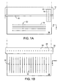
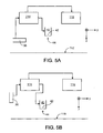
- a printer 10 having one or more printheads 12 (not all shown) each containing one or more rows of jets 14 (not all shown) prints lines 16 on a substrate 18 that is stationary.
- the printhead 12 scans across a width of the substrate 18 along a rail 20 (process direction y ) and prints lines 22 of successive dots that are parallel to the row of jets 14 ( x direction).
- each line 22 corresponds to one jet 14 in the row of jets and the density of the lines 22 along the x direction depends on the density of jets 14 in the row.
- the substrate 18 then moves a step along the x direction and the printhead 12 repeats the printing process across the substrate 18.
- a stationary printer 24 having one or more printheads 34 (not all shown) each containing one or more rows of jets 28 (not all shown) covers a width of an image that is intended to be printed on a substrate 26 (x direction) and prints lines 30 continuously.
- the printer 24 prints successive rows of dots 32 parallel to the row of jets ( x direction) when the substrate 26 passes under the jets 28 along the process direction y .
- US 2006/0071957 A1 discloses an apparatus and a method of visualizing droplets dispensed from an inkjet printing system.
- a droplet visualization system is integrated with the inkjet printing system and is capable of measuring the sizes and the speeds of dispensed inkjet droplets and capturing the trajectories of the dispensed inkjet droplets. The measured information regarding the sizes, the speeds and trajectories of the droplets is feedback to the inkjet printing system to monitor and to control the dispense operation of the inkjet printing system.
- US 2007/0070109 A1 discloses methods and apparatus for inkjet drop positioning.
- the method includes determining an intended deposition location of an ink drop on a substrate, depositing the ink drop on the substrate using an inkjet printing system, detecting a deposited location of the deposited ink drop on the substrate, comparing the deposited location to the intended location, determining a difference between the deposited location and the intended location, and compensating for the difference between the deposited location and the intended location by adjusting a parameter of an inkjet printing system.
- the invention relates to a system as defined in claim 1 and a method as defined in claim 11.
- the printhead includes at least 100 jets.
- the printhead includes at least 200 jets.
- the imaging device comprises a linescan camera.
- the imaging device comprises linearly arranged pixels, each pixel having a resolution of about 2 ⁇ m to about 10 ⁇ m.
- the imaging device comprises about 2000 pixels to about 12000 pixels.
- the imaging device takes images at a maximum frequency of at least about 5 KHz.
- the imaging device transfers image information at a rate of about 30 mega-pixels/second to about 50 mega-pixels/second.
- the system also includes a substrate onto which jets jet ink droplets and the image information is captured in a region between the jets and the substrate as the jetted ink droplets pass the region.
- the performance of each of the jets comprises at least one of a velocity of a droplet jetted from a corresponding jet, a size of the droplet, a shape of the droplet, a trajectory of the droplet, and distance between the droplet and its neighboring droplet perpendicular to a jetting direction.
- the imaging device is located about 50 mm to about 200 mm from the trajectory of droplets jetted from the jets.
- the system also includes a substrate onto which each jet jets ink droplets to print a line on the substrate, and the image information is of the printed line.
- the performance of the jets comprises straightness of the line and thickness of the line.
- the imaging device is located about 50 mm to about 200 mm from the substrate. The imaging device is stationary relative to the printhead.
- the system also includes a device for processing images produced by the imaging device and evaluating the performance of the jets.
- the system also includes a control to automatically adjust an aspect of the printhead based on the performance of the jets during ink jetting.
- a method for use in jetting ink, includes generating an image of a composite droplet based on at least two image portions that respectively capture image information for portions of ink droplets that are jetted from the ink jet at successive time periods, each time period being the period of the capturing of the image information.
- Implementations may include one or more of the following features.
- the droplets are successive droplets jetted from the jet.
- the image portions are generated at an imaging frequency different from a jetting frequency of the jet.
- the image portions of the droplets are composited along a jetting direction of the jet.
- the method also includes measuring the performance of the jet by calculating a velocity of the ink droplets based on the image of the composite droplet.
- the method also includes generating additional images of additional composite droplets and measuring the performance of the jet by calculating a trajectory of the ink droplets based on the image of the composite droplet and the additional images of the additional composite droplets.
- the method also includes adjusting an aspect of the jet based on the measured performance of the jet.
- the jet is included in a printhead having more than 25 jets and the method also includes simultaneously generating an image of a composite droplet based on at least two image portions that respectively capture image information for portions of ink droplets jetted from each jet.
- Each image slice has a resolution of about 2 ⁇ m to about 10 ⁇ m.
- Performance of the jets can be measured, analyzed, evaluated, and ameliorated by a system described here, both for a step-and-repeat printer or a single pass printer.
- the actions can be taken either during design or manufacture and before the jets are put into operation, and can be done quickly enough to be performed between executions of printing jobs. In some cases it may be possible to perform them continuously on the fly during a printing job. As a result, the design, manufacture, maintenance, and operation of the ink jets (and the quality of the images printed) can be improved.
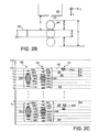
- a linescan camera 36 captures images of ink droplets 44 jetted from a printhead 40 (such as the printhead 12 or 34 of FIGS. 1A or 1B ) and the performance of the jets 42 in the printhead 40 is determined from the image information.
- the printhead 40 and a substrate 38 are arranged similarly to the arrangement of the printhead 34 and the substrate 26 of FIG 1B .
- the substrate 38 is a surface 45 of a drum 46 rotating about a longitudinal axis 48 parallel to the x direction.
- the jets 42 are in a row parallel to and above the longitudinal axis 48 and are a distance H (for example, about 1 mm to about 20 mm or about 1 mm to about 10 mm) above the substrate 38.
- the surface 45 can be a material that does not absorb ink, for example, a metal, so that the ink jetted onto the substrate 38 can be cleaned, for example, wiped, and t reused.
- Other substrates for example, a roll-to-roll web, can also be used.
- the linescan camera 36 focuses on a region 43 vertically below the jets 42, through which the jetted droplets 44 pass, to take images of the droplets 44 in mid-air.
- the linescan camera 36 is placed at a horizontal distance d from a line between the jets and the axis 48 and a vertical distance l above below the jets 42, such that the droplets can be imaged in focus by the camera.
- the distance d is, for example, at least about 40 mm, 50 mm, 60 mm, 70 mm, or 80 mm, and/or up to about 200 mm, 180 mm, 150 mm, 130 mm, or 100 mm and the distance l is, for example, about 1 mm to about 5 mm, which is similar to a distance from the jets 42 to a substrate when the jets 42 are in use in a printer.
- a lens (not shown) can be placed in front of the linescan camera 36 to form an in-focus image of the droplets, and a light source 50 can be placed, for example, at the opposite of the camera 36 to light the region 43 to aid imaging of the ink droplets.
- the linescan camera 36 can take high-resolution images each capturing all of the ink droplets 44 jetted from all jets 42 of printhead 40 at a given moment and repeat the capturing of successive images at a high frequency.
- the linescan camera 36 includes about 8000 to about 12000 pixels 52 arranged linearly and in parallel with the row of jets 42. Each pixel 52 has a resolution of about 2 ⁇ m to about 10 ⁇ m.
- the linescan camera 36 can take an image having a length L up to about 12 cm and a width w up to about 10 ⁇ m at a maximum resolution of each pixel, and simultaneously capturing all ink droplets from all jets 42 that are passing the camera.
- Multiple images can be taken successively at a maximum frequency f i , for example, of at least 5 KHz, 6 KHz, 7 KHz, or 8 KHz, and/or up to about 12 KHz, 11 KHz, or 10 KHz and image information can be delivered at a rate of about 30 mega-pixels/second to about 50 mega-pixels/second, for example, 40 mega-pixels/second (eight bits or one byte of information for each pixel).
- Information about characteristics of the droplets 44 can be extracted from the image information and the jet performance measurements for the printhead 40 can be done within a short period of time, for example, seconds, and information about the performance of an individual jet relative to the other jets can also be obtained.
- the linescan camera 36 can be a P/N P2-23-08k40 camera available from Dalsa Corp (Waterloo, Canada).
- all jets 42 are activated by selected voltages delivered at a maximum jetting frequency f j to print a row of dots 32 ( FIG. 1B ).
- the maximum jetting frequency f j is about 2 KHz to about 100 KHz, for example, about 5KHz to about 10 KHz.
- the voltage applied to the pumping chamber of each jet is about 10 V to about 100 V, for example, about 20 V to about 80 V, and can generate droplets that move to the substrate at different speeds, for example, about 2 m/s to about 20 m/s.
- different jets 42 can be activated by different voltages or at frequencies lower than the maximum frequency f j . Patterns other than continuous lines 30 can be formed on the substrate 38.
- the linescan camera 36 has an imaging range I along a jetting direction z.
- the imaging range I is about two times the diameter D of each droplet 44 and the width w (assuming the droplet is substantially round. Droplets can have other shapes, for example, round droplets with long tails).
- each droplet 44 is about 1 picoliter to about 100 picoliters or more, so the diameter D of each droplet 44 is about 10 ⁇ m and/or up to about 50 ⁇ m and is larger than the imaging width w of the linescan camera 36.
- the imaging range I of the linescan camera 36 and the linescan camera is taking an image only a portion, for example, about 1/10 or less to about 1/2, of the droplet 44 is captured in the image.
- the imaging range I can vary based on the shape of the droplets 44.
- the imaging frequency f i of linescan camera 36 can be n f j or 1/(n f j ), where n is a positive integer and f j is the jetting frequency of the row of jets 42.
- the velocity of the droplets 44 and a vertical distance L between the linescan camera 36 and the jets 42 can be adjusted so that at least a portion of one droplet 44 from one jet 42 can be captured in an image 56 in the form of an image slice.
- the imaged droplets 44 from one particular jet are shown as a composite of stacked slices in image 54 in FIG. 2C .
- a portion of the first droplet 44a is imaged at time t 1 and the same portion of a second droplet 44b from the same jet is imaged at t 2 , where t 2 -t 1 is the period between successive imaging.
- the imaging frequency f i being n times or 1/n fraction of the jetting frequency f j
- the imaged small portions of the droplets 44 on each image slice 56 may be of only modest value in analyzing the jet performance.
- droplets from some of the jets 42 can be missed in the images because of the response delay of those jets relative to the jets being properly imaged or velocity differences of the ink droplets 44 from different jets.
- the imaging frequency f i of linescan camera 36 can be smaller than 2 f j but different from 1/(n f j ).
- a time difference ⁇ T between the imaging period T i (which is the inverse of the imaging frequency) of the linescan camera 36 and multiples of the jetting period nT j (T j being the inverse of the jetting frequency of the row of jets 42) can be introduced to produce multiple image slices 56 that can be assembled into an image of a composite droplet.
- the image of the composite droplet is not an image of a single droplet but rather how the droplet 44 would be characterized based on an assumption that drops jetted from a single jet using a given activation voltage and at a constant jetting frequency will tend to have the same characteristics.
- the time difference ⁇ T can be selected to be a fraction, for example, 1/2, 1/4, 1/10, or other fractions, of I/(velocity of the droplet).
- a portion of the first droplet 44c from one jet is captured in image slice 56 taken at t 1 shown in image 58 of FIG. 2C .
- the linescan camera 36 takes an image at t 2 that is one period T i after t 1
- a second droplet 44d from the same jet is passing the image range but located (2 ⁇ s x velocity of the droplet 44d) vertically above the position of the first droplet 44c at which it was imaged relative to the imaging range.
- each jet 42 jets droplets having substantially identical characteristics the composite droplet 60 can be a good representative of the characteristics of each of the droplets 44c-44i.
- a size and shape of each droplet can be calculated from the image of the composite droplet 60.
- composite droplets like the composite droplet 60 can also be generated using successive image slices like the image slices 56, but each successive slices capturing one of non-successive droplets (separated at least by time ( k- 1)T j ) jetted from the jet.
- the velocity of a droplet from the jet 42 can be calculated by dividing the vertical distance L by the time the droplet flies from the jet 42 into the imaging range I, which can be derived from the image information of the stacked image slices of FIG. 2C .
- the velocity of the droplets from on particular jet 42 can be calculated to be L/( ⁇ T x (t 1 /T j -1)).
- T j is larger than the total flying time of a droplet between the jets 42 and the substrate 38, or when the droplet velocity is high and the jetting frequency is low.
- velocities of the droplets can be obtained by processing the calculated values from L/( ⁇ T x (t 1 /T i -1)).
- a calculated value for each jet 42 can be filtered, e.g., to limit the values to be between a reasonable range, such as about 2 m/s to about 20 m/s, or averaging multiple, filtered calculated values from more than one composite droplets, e.g., about 10 composite droplets.
- Other algorithms can be used to calculate the droplet velocities based on the images of the composite droplets.
- the obtained droplet velocity for each jet can have a high precision, for example, within 1% range of variation.
- an image 62 of a composite droplet 64 can be produced in a similar way as the image 58 of the composite droplet 60, except that the each droplet in successive or non-successive droplets 44j-44p is located (2 ⁇ s x velocity of the droplet 44b) below the position of a directly previous droplet relative to the imaging range I at the moment when an image of each droplet is taken. Based on the same assumptions, the velocity, size, and shape of the droplets represented by the composite droplet 64 can be calculated.
- the total number of image slices 56 used to generate the image 58 or 62 of composite droplet 60 or 64 can be selected by choosing a suitable time difference ⁇ T.
- Each droplet passes the image range of the linescan camera 36 in a time period of about (2D+ w )/(velocity of the droplet).
- the time difference ⁇ T can be selected to be (2D+w)/(velocity of the droplet x q ).
- the velocity of the droplet can be an estimation.
- one or more subsequent droplets can pass the imaging range without being imaged, until at time t n , a portion of a droplet 44c' or 44j' is captured in an image slice. Portions of subsequent droplets 44d'-44i' or 44k'-44p' can be captured in image slices 56' and images of composite droplet 60' and 64' can be produced.
- the images of the composite droplets 60 and 60' or 64 and 64' (or more composite droplets) generated from droplets jetted from a given jet can be used to measure a trajectory of a droplet from that jet.
- the trajectory measurement can have a high precision, for example, in the order of one milliradian.
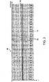
- an image portion 66 made of the stacked image slices 56 (exemplary, size not to scale) covering a width of 32 jets (horizontal axis, jets number 15-46) of the printhead 40 is intercepted from full width, stacked image slices that cover a width of all jets 42, e.g., 256 jets, of the printhead 40 and is enlarged for view and analysis.
- the jetting frequency of the row of jets 42 is about 5 KHz.
- images of 2 to 3 composite droplets are generated, each from about 12 image slices 56 or 12 droplets.
- the image representing the droplets from all jets in the printhead can be formed rapidly, for example, 100 image slices 56 can be captured in about 20 milliseconds.
- Post imaging process for example, filtering to sharpen the images, placing straightness reference lines 68, and/or placing jet IDs 70, can be done to facilitate analysis of the image portion 66 and evaluation of the jet performance of the printhead 40.
- Information about jet performance in the printhead 40, other than the velocity, size, and shape, of the jetted droplets as described above, can be obtained from the image portion 66.
- weak and unstable jets J18 and J29 and missing jets J37 and J45 are identified.
- the response upon activation and velocities of the jetted droplets, for example, of jets J16 and J20, are different from those, for example, of jets J32 and J36.
- the distance between different pairs of droplets jetted from neighboring jets indicating the distance between pairs of corresponding jets, are not all the same.
- droplets jetted from jet J27 are closer to droplets jetted from J26 than to droplets jetted from J28.
- Other useful information about the performance of the jets can also be extracted from the image portion 66.
- the information from the jet performance measurements can be used in deigning, manufacturing, maintaining, and application of the printhead 40.
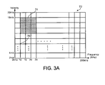
- each grid 76 represents one jetting frequency in the range of 5 KHz and 200 KHz and one droplet velocity in the range of 2 m/s and 20 m/s.
- the low quality performance of a jet when activated by a high voltage and jetting droplets with a high speed can be identified, for example, in an image portion 78 of FIG. 3B , in which droplets, for example, composite droplets 80 and 82, have long tails 84 and 86.
- One image like image portion 66 can be produced for each grid 76 of FIG. 3A for the printhead 40 and an optimal performance range 74, for example, 10 KHz to 25 KHz and 12 m/s to 18 m/s, for all jets in the printhead can be identified.
- the performance of the jets is measured when different activation voltages are applied to different jets.
- an image portion 88 of FIG. 3C shows composite droplets 90 having a high velocity and jetted from odd numbered jets each activated by a high voltage and composite droplets 92 having a low velocity and jetted from even numbered jets each activated by a low voltage.
- Composite droplets 90 have longer tails than composite droplets 92.
- the high and low voltages applied to the two sets of jets can be adjusted independently to find an optimal range of activation voltages (therefore, droplet velocities), within which all jets to perform with high quality.
- jet performance can also be measured by monitoring an output, e.g., an image, formed on a substrate by the jetted ink droplets.
- jet performance can be measured by monitoring both the ink droplets in air and the output formed by the output simultaneously.
- an image 94 containing parallel lines 100 is formed on a substrate, for example, paper, using the ink jet printer 10 of FIG. 1A or ink jet printer 24 of FIG. 1B when each jet 14 or 28 is activated to jet ink droplets at a jetting frequency of each row of the jets.
- An image 96 maintaining a resolution of the image 94 and magnifying the features of each line 100 is generated using the linescan camera 36 as described previously.
- the linescan camera 36 placed about 50 mm to about 100 mm above the image 94 scans the image 94 along a direction parallel to the lines 100 and produces successive image slices (not shown) that are stacked along the scanning direction of the camera.
- the image 96 can be used for analyzing straightness and/or line width of each line 100. To facilitate such an analysis, it is desirable that the image 96 does not include interferences, for example, textures of the paper substrate on which the lines 100 are formed.
- an image 102 is generated using the linescan camera 36 in a manner similar to the generation of image 96 based on a processed, e.g., filtered, image 98 of the image 94. Similar to the image portion 66 of FIG. 3 , the image 102 is also processed to include jet IDs 106 and straightness reference lines 108 to assist the analysis of the image.
- a sample portion 104 of the processed image 102 shows lines 100 printed by jets having IDs from 144 to 169. Quality, e.g., the straightness and the width, of each printed line is rated using crosses ("+") 110: the closer the cross 100 is to the center line 100, the straighter the printed line 110 is, and therefore, the higher quality performance the corresponding jet demonstrates.
- the line printed by jet 156 shows poor straightness and has a cross 110 located vertically high to indicate poor performance of the jet 156.
- the monitoring of the output formed by the jets can also be used in studying the optimal ranges for jetting frequency and droplet velocity of a printhead similar to the application of the linescan camera 36 in the droplet monitoring at different jetting frequencies and droplet velocities discussed with respect to FIG. 3A .
- the use of the linescan camera 36 in the monitoring of the output allows fast and simultaneous analysis of the performance of each jet in a printhead.
- the jet performance measurements described above can also be done when the printer 10 of FIG. 1A or the printer 24 of FIG. 1B is executing printing jobs.
- the linescan camera 36 is kept stationary with respect to the printhead 40 of a step-and-repeat printer or a single pass printer that is executing printing jobs and monitors the ink droplets 44 jetted by the printhead 40 in a manner similar to that described in FIGS. 2, 2A and 2B .
- the images produced by the linescan camera 36 is processed in a processor 114 to produce measurements of the performance of the jets in printhead 40.
- the measurements can be delivered to a user interface 116, for example, a computer screen, for a user's review.
- the user can adjust a status or an aspect of the printhead, for example, stopping the printing job temporarily for maintenance of the printhead to improve the jet performance.
- the measurements can also be sent as a feedback to a control (not shown) of the printhead 40 so that adjustments, for example, change of an activation voltage associated one or more particular jets, can be done without interrupting the printing job to improve the jet performance in subsequent portions of the printing job, for example, printing of a subsequent page.
- the linescan camera 36, processor 114, and user interface 116 of FIG. 5A can also be used to monitor the output of the printhead 40 on a substrate 118 to measure the performance of the jets in the printhead 40 as explained above.
- the printhead 36 is located in parallel with and behind (downstream of) the row of jets in printhead 40 along a process direction of the printing job (the substrate 118 moving in the y direction when the printhead 40 is in a single pass printer or the printhead 40 and the linescan camera 36 moving along they direction when the printhead 40 is in a step-and-repeat printer) so that the linescan camera 36 generates images of the output substantially synchronously with the formation of the output by the printhead 40 on the substrate 118.
- Status or aspect correction or adjustment of the printhead 40 can be done without interrupting the printing process based on the measurements of the jet performance.
- ink as the printing fluid
- ink in a sense that includes a wide variety of printing and other fluids including non-image forming fluids.
- three-dimensional model pastes can be selectively deposited to build models.
- Biological samples can be deposited on an analysis array.
- imaging device we sometimes use the phrase imaging device to refer to a linescan camera and any other kind of device that can capture images.
Description
- This description relates to jet performance.
- The quality of an image or a product formed on a substrate by ink jetted from an ink jet printer can be affected by the performance of jets in the printhead of the printer. The jets in some printheads are arranged in one or more rows, in a direction different from, e.g., perpendicular to, a process direction of the printer. Each jet includes a pumping chamber to receive and pump ink and a nozzle to jet ink from the pumping chamber to the substrate. By applying an activation voltages to a piezoelectric element associated with each pumping chamber ink droplets can be jetted based on information about the image to be printed.
- Typically, the jets in each row are identical and each pair of neighboring jets along a row are separated by equal spaces. Each row of jets can be about 1 inch to about 3 inches long and can contain at least 25 jets or 50 jets and up to about 500 jets, for example. Each jetted ink droplet can have a size of about 2 picoliters to about 100 picoliters, based on dimensions of the jet and the voltages applied to the jet.
- Generally, a jet is built for jetting one size of ink droplet in response to a particular activation voltage at a jetting frequency that is within a particular range. If the voltage varies or the jet is activated at a frequency outside the frequency range, the jet may perform poorly or even stop working. Sometimes a jet is built for jetting several different-sized ink droplets, each in response to a particular activation voltage and within a certain frequency range of jetting. Discussion of different types of printheads and jets is provided, for example, in
U.S. 5,265,315 ,U.S. 7,052,117 ,USSN 10/800,467, filed March 15, 2004 USSN 11/652,325, filed January 11, 2007 USSN 12/125,648, filed May 22, 2008 - Even when a jet is driven at the intended activation voltage and within the intended frequency range, the quality of the ink droplets (and the resulting printing) can be degraded by manufacturing flaws in, or a temporary malfunction of, the jet (air bubbles, or ink adhering to the nozzle, for example). Temporary malfunctions sometimes can be corrected.
- The performance of a jet can be gauged in several ways. One technique analyzes quantifiable properties of ink droplets that it jets, for example, their size, speed, or trajectory. Another approach compares its performance to the performance of other jets in the row, for example, the response of the jet upon activation relative to the other jets or the speed of the jetted ink droplets relative to ink droplets jetted by the other jets. The performance can also be gauged by analyzing an image or product the jet prints, for example, information about whether a dot printed by the jet appears at an intended position with an intended size and shape on the substrate or whether a line printed by the jet is straight and has an intended thickness.
- As shown in
FIGS. 1A and 1B , in step-and-repeat printing, aprinter 10 having one or more printheads 12 (not all shown) each containing one or more rows of jets 14 (not all shown)prints lines 16 on asubstrate 18 that is stationary. Theprinthead 12 scans across a width of thesubstrate 18 along a rail 20 (process direction y) andprints lines 22 of successive dots that are parallel to the row of jets 14 (x direction). In this example, eachline 22 corresponds to onejet 14 in the row of jets and the density of thelines 22 along the x direction depends on the density ofjets 14 in the row. Thesubstrate 18 then moves a step along the x direction and theprinthead 12 repeats the printing process across thesubstrate 18. - Referring to
FIG. 1B , in single pass printing, astationary printer 24 having one or more printheads 34 (not all shown) each containing one or more rows of jets 28 (not all shown) covers a width of an image that is intended to be printed on a substrate 26 (x direction) andprints lines 30 continuously. Theprinter 24 prints successive rows ofdots 32 parallel to the row of jets (x direction) when thesubstrate 26 passes under thejets 28 along the process direction y. -
US 2006/0071957 A1 discloses an apparatus and a method of visualizing droplets dispensed from an inkjet printing system. A droplet visualization system is integrated with the inkjet printing system and is capable of measuring the sizes and the speeds of dispensed inkjet droplets and capturing the trajectories of the dispensed inkjet droplets. The measured information regarding the sizes, the speeds and trajectories of the droplets is feedback to the inkjet printing system to monitor and to control the dispense operation of the inkjet printing system. -
US 2007/0070109 A1 discloses methods and apparatus for inkjet drop positioning. The method includes determining an intended deposition location of an ink drop on a substrate, depositing the ink drop on the substrate using an inkjet printing system, detecting a deposited location of the deposited ink drop on the substrate, comparing the deposited location to the intended location, determining a difference between the deposited location and the intended location, and compensating for the difference between the deposited location and the intended location by adjusting a parameter of an inkjet printing system. - The invention relates to a system as defined in
claim 1 and a method as defined inclaim 11. - Implementations may include one or more of the following features. The printhead includes at least 100 jets. The printhead includes at least 200 jets. The imaging device comprises a linescan camera. The imaging device comprises linearly arranged pixels, each pixel having a resolution of about 2 µm to about 10 µm. The imaging device comprises about 2000 pixels to about 12000 pixels. The imaging device takes images at a maximum frequency of at least about 5 KHz. The imaging device transfers image information at a rate of about 30 mega-pixels/second to about 50 mega-pixels/second. The system also includes a substrate onto which jets jet ink droplets and the image information is captured in a region between the jets and the substrate as the jetted ink droplets pass the region. The performance of each of the jets comprises at least one of a velocity of a droplet jetted from a corresponding jet, a size of the droplet, a shape of the droplet, a trajectory of the droplet, and distance between the droplet and its neighboring droplet perpendicular to a jetting direction. The imaging device is located about 50 mm to about 200 mm from the trajectory of droplets jetted from the jets. The system also includes a substrate onto which each jet jets ink droplets to print a line on the substrate, and the image information is of the printed line. The performance of the jets comprises straightness of the line and thickness of the line. The imaging device is located about 50 mm to about 200 mm from the substrate. The imaging device is stationary relative to the printhead. At least some of the jets are arranged in a row. The system also includes a device for processing images produced by the imaging device and evaluating the performance of the jets. The system also includes a control to automatically adjust an aspect of the printhead based on the performance of the jets during ink jetting.
- In another aspect, for use in jetting ink, a method includes generating an image of a composite droplet based on at least two image portions that respectively capture image information for portions of ink droplets that are jetted from the ink jet at successive time periods, each time period being the period of the capturing of the image information.
- Implementations may include one or more of the following features. The droplets are successive droplets jetted from the jet. The image portions are generated at an imaging frequency different from a jetting frequency of the jet. The image portions of the droplets are composited along a jetting direction of the jet. The method also includes measuring the performance of the jet by calculating a velocity of the ink droplets based on the image of the composite droplet. The method also includes generating additional images of additional composite droplets and measuring the performance of the jet by calculating a trajectory of the ink droplets based on the image of the composite droplet and the additional images of the additional composite droplets. The method also includes adjusting an aspect of the jet based on the measured performance of the jet. The jet is included in a printhead having more than 25 jets and the method also includes simultaneously generating an image of a composite droplet based on at least two image portions that respectively capture image information for portions of ink droplets jetted from each jet. Each image slice has a resolution of about 2 µm to about 10 µm.
- These and other aspects and features, and combinations of them, can be expressed as methods, apparatus, systems, means for performing a function, and in other ways.
- Other features and advantages will be apparent from the following detailed description, and from the claims.
-
-
FIGS. 1A and 1B are schematic top views of printers (not to scale). -
FIGS. 2 and 2A are a schematic side view and a schematic front view of a system for jet performance measurements (not to scale). -
FIG. 2B is an enlarged schematic side view of a portion of the system ofFIG. 2 (not to scale). -
FIG 2C is a schematic view of image slices. -
FIGS. 3 ,3B and 3C are photographs. -
FIG. 3A is a grid of a jetting frequency range and a droplet velocity range. -
FIGS. 4A and 4B are photographs. -
FIGS. 5A and 5B are block diagrams. - Performance of the jets can be measured, analyzed, evaluated, and ameliorated by a system described here, both for a step-and-repeat printer or a single pass printer. The actions can be taken either during design or manufacture and before the jets are put into operation, and can be done quickly enough to be performed between executions of printing jobs. In some cases it may be possible to perform them continuously on the fly during a printing job. As a result, the design, manufacture, maintenance, and operation of the ink jets (and the quality of the images printed) can be improved.
- Referring to
FIG. 2 , in some examples, alinescan camera 36 captures images ofink droplets 44 jetted from a printhead 40 (such as theprinthead FIGS. 1A or 1B ) and the performance of thejets 42 in theprinthead 40 is determined from the image information. In this example, theprinthead 40 and asubstrate 38 are arranged similarly to the arrangement of theprinthead 34 and thesubstrate 26 ofFIG 1B . Here, for purposes of performance measurements, thesubstrate 38 is asurface 45 of adrum 46 rotating about alongitudinal axis 48 parallel to the x direction. Thejets 42 are in a row parallel to and above thelongitudinal axis 48 and are a distance H (for example, about 1 mm to about 20 mm or about 1 mm to about 10 mm) above thesubstrate 38. Thesurface 45 can be a material that does not absorb ink, for example, a metal, so that the ink jetted onto thesubstrate 38 can be cleaned, for example, wiped, and t reused. Other substrates, for example, a roll-to-roll web, can also be used. - The
linescan camera 36 focuses on aregion 43 vertically below thejets 42, through which the jetteddroplets 44 pass, to take images of thedroplets 44 in mid-air. Thelinescan camera 36 is placed at a horizontal distance d from a line between the jets and theaxis 48 and a vertical distance l above below thejets 42, such that the droplets can be imaged in focus by the camera. The distance d is, for example, at least about 40 mm, 50 mm, 60 mm, 70 mm, or 80 mm, and/or up to about 200 mm, 180 mm, 150 mm, 130 mm, or 100 mm and the distance l is, for example, about 1 mm to about 5 mm, which is similar to a distance from thejets 42 to a substrate when thejets 42 are in use in a printer. In some embodiments, a lens (not shown) can be placed in front of thelinescan camera 36 to form an in-focus image of the droplets, and alight source 50 can be placed, for example, at the opposite of thecamera 36 to light theregion 43 to aid imaging of the ink droplets. - Referring to
FIG. 2A , thelinescan camera 36 can take high-resolution images each capturing all of theink droplets 44 jetted from alljets 42 ofprinthead 40 at a given moment and repeat the capturing of successive images at a high frequency. Thelinescan camera 36 includes about 8000 to about 12000pixels 52 arranged linearly and in parallel with the row ofjets 42. Eachpixel 52 has a resolution of about 2 µm to about 10 µm. In the example shown in the figure, thelinescan camera 36 can take an image having a length L up to about 12 cm and a width w up to about 10 µm at a maximum resolution of each pixel, and simultaneously capturing all ink droplets from alljets 42 that are passing the camera. Multiple images can be taken successively at a maximum frequency fi, for example, of at least 5 KHz, 6 KHz, 7 KHz, or 8 KHz, and/or up to about 12 KHz, 11 KHz, or 10 KHz and image information can be delivered at a rate of about 30 mega-pixels/second to about 50 mega-pixels/second, for example, 40 mega-pixels/second (eight bits or one byte of information for each pixel). Information about characteristics of thedroplets 44 can be extracted from the image information and the jet performance measurements for theprinthead 40 can be done within a short period of time, for example, seconds, and information about the performance of an individual jet relative to the other jets can also be obtained. Thelinescan camera 36 can be a P/N P2-23-08k40 camera available from Dalsa Corp (Waterloo, Canada). - During the jet performance measurements, all
jets 42 are activated by selected voltages delivered at a maximum jetting frequency fj to print a row of dots 32 (FIG. 1B ). The maximum jetting frequency fj is about 2 KHz to about 100 KHz, for example, about 5KHz to about 10 KHz. The voltage applied to the pumping chamber of each jet is about 10 V to about 100 V, for example, about 20 V to about 80 V, and can generate droplets that move to the substrate at different speeds, for example, about 2 m/s to about 20 m/s. In some embodiments,different jets 42 can be activated by different voltages or at frequencies lower than the maximum frequency fj . Patterns other thancontinuous lines 30 can be formed on thesubstrate 38. - Referring to
FIG. 2B , thelinescan camera 36 has an imaging range I along a jetting direction z. When anink droplet 44 is anywhere within the imaging range, at least some part of the droplet can be captured in an image thelinescan camera 36 takes. The imaging range I is about two times the diameter D of eachdroplet 44 and the width w (assuming the droplet is substantially round. Droplets can have other shapes, for example, round droplets with long tails). As explained above, eachdroplet 44 is about 1 picoliter to about 100 picoliters or more, so the diameter D of eachdroplet 44 is about 10 µm and/or up to about 50 µm and is larger than the imaging width w of thelinescan camera 36. Accordingly, when adroplet 44 passes the imaging range I of thelinescan camera 36 and the linescan camera is taking an image, only a portion, for example, about 1/10 or less to about 1/2, of thedroplet 44 is captured in the image. The imaging range I can vary based on the shape of thedroplets 44. - The imaging frequency fi of
linescan camera 36 can be n fj or 1/(nfj ), where n is a positive integer and fj is the jetting frequency of the row ofjets 42. The velocity of thedroplets 44 and a vertical distance L between thelinescan camera 36 and thejets 42 can be adjusted so that at least a portion of onedroplet 44 from onejet 42 can be captured in animage 56 in the form of an image slice. By capturing successive images of successive or non-successive droplets jetted from a jet, image slices of the drop can be captured and the image slices 56 can be "stacked" along the jetting direction z. - For example, the imaged
droplets 44 from one particular jet are shown as a composite of stacked slices inimage 54 inFIG. 2C . A portion of thefirst droplet 44a is imaged at time t1 and the same portion of asecond droplet 44b from the same jet is imaged at t2, where t2-t1 is the period between successive imaging. In this approach (the imaging frequency fi being n times or 1/n fraction of the jetting frequency fj ), the imaged small portions of thedroplets 44 on eachimage slice 56 may be of only modest value in analyzing the jet performance. In addition, droplets from some of thejets 42 can be missed in the images because of the response delay of those jets relative to the jets being properly imaged or velocity differences of theink droplets 44 from different jets. - The imaging frequency fi of
linescan camera 36 can be smaller than 2fj but different from 1/(nfj ). A time difference ΔT between the imaging period Ti (which is the inverse of the imaging frequency) of thelinescan camera 36 and multiples of the jetting period nTj (Tj being the inverse of the jetting frequency of the row of jets 42) can be introduced to produce multiple image slices 56 that can be assembled into an image of a composite droplet. The image of the composite droplet is not an image of a single droplet but rather how thedroplet 44 would be characterized based on an assumption that drops jetted from a single jet using a given activation voltage and at a constant jetting frequency will tend to have the same characteristics. The time difference ΔT can be selected to be a fraction, for example, 1/2, 1/4, 1/10, or other fractions, of I/(velocity of the droplet). Thelinescan camera 32 can start imaging simultaneously with the activation of the row ofjets 42 to jet a first droplet from each jet at time zero and after mTi, a portion of adroplet 44 is captured in the (m+1)th image slice, where m=0, 1, 2, .... - When Ti is smaller than kTj but larger than (k-1/2)Tj, where k=1, 2,..., for example, Ti is 198 µs, Tj is 200 µs, and ΔT is 2 µs, a portion of the
first droplet 44c from one jet is captured inimage slice 56 taken at t1 shown inimage 58 ofFIG. 2C . Subsequently, when thelinescan camera 36 takes an image at t2 that is one period Ti after t1, asecond droplet 44d from the same jet is passing the image range but located (2 µs x velocity of thedroplet 44d) vertically above the position of thefirst droplet 44c at which it was imaged relative to the imaging range. Similarly, different portions ofsuccessive droplets 44e-44i are captured by successive image slices due to the time difference ΔT. When these image slices are stacked along the jetting direction z, the portions ofdroplets 44c-44i generate one largecomposite droplet 60. Assuming that eachjet 42 jets droplets having substantially identical characteristics, thecomposite droplet 60 can be a good representative of the characteristics of each of thedroplets 44c-44i. A size and shape of each droplet can be calculated from the image of thecomposite droplet 60. In other examples when k is larger than 1, composite droplets like thecomposite droplet 60 can also be generated using successive image slices like the image slices 56, but each successive slices capturing one of non-successive droplets (separated at least by time (k-1)Tj) jetted from the jet. - The velocity of a droplet from the
jet 42 can be calculated by dividing the vertical distance L by the time the droplet flies from thejet 42 into the imaging range I, which can be derived from the image information of the stacked image slices ofFIG. 2C . For example, when thelinescan camera 36 and thejets 42 are so adjusted that at any moment, there is at most onedroplet 44 from eachjet 42 flying between vertical distance between the jets and thecamera 36, then usingimages FIG. 2C , the velocity of the droplets from onparticular jet 42 can be calculated to be L/(ΔT x (t1/Tj-1)). Generally, conditions for such an arrangement are satisfied when Tj is larger than the total flying time of a droplet between thejets 42 and thesubstrate 38, or when the droplet velocity is high and the jetting frequency is low. In situations when more than one droplets are flying between thejets 42 and the substrate 38 (FIG. 2 ), velocities of the droplets can be obtained by processing the calculated values from L/(ΔT x (t1/Ti-1)). For example, a calculated value for eachjet 42 can be filtered, e.g., to limit the values to be between a reasonable range, such as about 2 m/s to about 20 m/s, or averaging multiple, filtered calculated values from more than one composite droplets, e.g., about 10 composite droplets. Other algorithms can be used to calculate the droplet velocities based on the images of the composite droplets. The obtained droplet velocity for each jet can have a high precision, for example, within 1% range of variation. - When Ti is larger than kTj but smaller than (k+1/2)Tj, where k=1, 2, 3, ..., an
image 62 of acomposite droplet 64 can be produced in a similar way as theimage 58 of thecomposite droplet 60, except that the each droplet in successive ornon-successive droplets 44j-44p is located (2 µs x velocity of thedroplet 44b) below the position of a directly previous droplet relative to the imaging range I at the moment when an image of each droplet is taken. Based on the same assumptions, the velocity, size, and shape of the droplets represented by thecomposite droplet 64 can be calculated. - The total number of image slices 56 used to generate the
image composite droplet linescan camera 36 in a time period of about (2D+w)/(velocity of the droplet). To capture q successive or non-successive droplets in q successive image slices to generate a composite droplet, the time difference ΔT can be selected to be (2D+w)/(velocity of the droplet x q). Prior to the performance measurement of the jets, the velocity of the droplet can be an estimation. - After capturing the
final droplet non-successive droplets 44c-44i or 44j-44p passing the imaging range I of thelinescan camera 36, one or more subsequent droplets can pass the imaging range without being imaged, until at time tn, a portion of adroplet 44c' or 44j' is captured in an image slice. Portions ofsubsequent droplets 44d'-44i' or 44k'-44p' can be captured in image slices 56' and images of composite droplet 60' and 64' can be produced. The images of thecomposite droplets - Referring to
FIG. 3 , animage portion 66 made of the stacked image slices 56 (exemplary, size not to scale) covering a width of 32 jets (horizontal axis, jets number 15-46) of theprinthead 40 is intercepted from full width, stacked image slices that cover a width of alljets 42, e.g., 256 jets, of theprinthead 40 and is enlarged for view and analysis. The jetting frequency of the row ofjets 42 is about 5 KHz. For each of most jets shown in the figures, images of 2 to 3 composite droplets are generated, each from about 12 image slices 56 or 12 droplets. The image representing the droplets from all jets in the printhead can be formed rapidly, for example, 100 image slices 56 can be captured in about 20 milliseconds. Post imaging process, for example, filtering to sharpen the images, placingstraightness reference lines 68, and/or placingjet IDs 70, can be done to facilitate analysis of theimage portion 66 and evaluation of the jet performance of theprinthead 40. - Information about jet performance in the
printhead 40, other than the velocity, size, and shape, of the jetted droplets as described above, can be obtained from theimage portion 66. For example, weak and unstable jets J18 and J29 and missing jets J37 and J45 are identified. The response upon activation and velocities of the jetted droplets, for example, of jets J16 and J20, are different from those, for example, of jets J32 and J36. In addition, the distance between different pairs of droplets jetted from neighboring jets, indicating the distance between pairs of corresponding jets, are not all the same. For example, droplets jetted from jet J27 are closer to droplets jetted from J26 than to droplets jetted from J28. Other useful information about the performance of the jets can also be extracted from theimage portion 66. The information from the jet performance measurements can be used in deigning, manufacturing, maintaining, and application of theprinthead 40. - Multiple images like the
image portion 66 can be produced, each measuring the performance of the jets in theprinthead 40 at a selected jetting frequency and droplet velocity (selected by choosing a voltage that is applied to the jets) to identify a range of jetting frequency and droplet velocity for which high quality performance is achieved, or to determine whether the jets demonstrate high quality performance within an intended range of jetting frequency and droplet velocity as designed. For example, referring toFIG. 3A , eachgrid 76 represents one jetting frequency in the range of 5 KHz and 200 KHz and one droplet velocity in the range of 2 m/s and 20 m/s. The low quality performance of a jet when activated by a high voltage and jetting droplets with a high speed can be identified, for example, in animage portion 78 ofFIG. 3B , in which droplets, for example,composite droplets long tails image portion 66 can be produced for eachgrid 76 ofFIG. 3A for theprinthead 40 and anoptimal performance range 74, for example, 10 KHz to 25 KHz and 12 m/s to 18 m/s, for all jets in the printhead can be identified. - In some embodiments, the performance of the jets is measured when different activation voltages are applied to different jets. For example, an
image portion 88 ofFIG. 3C showscomposite droplets 90 having a high velocity and jetted from odd numbered jets each activated by a high voltage andcomposite droplets 92 having a low velocity and jetted from even numbered jets each activated by a low voltage.Composite droplets 90 have longer tails thancomposite droplets 92. The high and low voltages applied to the two sets of jets can be adjusted independently to find an optimal range of activation voltages (therefore, droplet velocities), within which all jets to perform with high quality. - Instead of monitoring ink droplets jetted from the jets to measure the performance of the jets as described above, jet performance can also be measured by monitoring an output, e.g., an image, formed on a substrate by the jetted ink droplets. In some embodiments, jet performance can be measured by monitoring both the ink droplets in air and the output formed by the output simultaneously.
- Referring to
FIG. 4A , animage 94 containingparallel lines 100 is formed on a substrate, for example, paper, using theink jet printer 10 ofFIG. 1A orink jet printer 24 ofFIG. 1B when eachjet image 96 maintaining a resolution of theimage 94 and magnifying the features of eachline 100 is generated using thelinescan camera 36 as described previously. In particular, thelinescan camera 36 placed about 50 mm to about 100 mm above theimage 94 scans theimage 94 along a direction parallel to thelines 100 and produces successive image slices (not shown) that are stacked along the scanning direction of the camera. Theimage 96 can be used for analyzing straightness and/or line width of eachline 100. To facilitate such an analysis, it is desirable that theimage 96 does not include interferences, for example, textures of the paper substrate on which thelines 100 are formed. - Referring to
FIG. 4B , animage 102 is generated using thelinescan camera 36 in a manner similar to the generation ofimage 96 based on a processed, e.g., filtered,image 98 of theimage 94. Similar to theimage portion 66 ofFIG. 3 , theimage 102 is also processed to includejet IDs 106 andstraightness reference lines 108 to assist the analysis of the image. Asample portion 104 of the processedimage 102 showslines 100 printed by jets having IDs from 144 to 169. Quality, e.g., the straightness and the width, of each printed line is rated using crosses ("+") 110: the closer thecross 100 is to thecenter line 100, the straighter the printedline 110 is, and therefore, the higher quality performance the corresponding jet demonstrates. For example, the line printed by jet 156 shows poor straightness and has across 110 located vertically high to indicate poor performance of the jet 156. - The monitoring of the output formed by the jets can also be used in studying the optimal ranges for jetting frequency and droplet velocity of a printhead similar to the application of the
linescan camera 36 in the droplet monitoring at different jetting frequencies and droplet velocities discussed with respect toFIG. 3A . The use of thelinescan camera 36 in the monitoring of the output allows fast and simultaneous analysis of the performance of each jet in a printhead. - The jet performance measurements described above can also be done when the
printer 10 ofFIG. 1A or theprinter 24 ofFIG. 1B is executing printing jobs. Referring toFIG. 5A , thelinescan camera 36 is kept stationary with respect to theprinthead 40 of a step-and-repeat printer or a single pass printer that is executing printing jobs and monitors theink droplets 44 jetted by theprinthead 40 in a manner similar to that described inFIGS. 2, 2A and2B . The images produced by thelinescan camera 36 is processed in aprocessor 114 to produce measurements of the performance of the jets inprinthead 40. The measurements can be delivered to auser interface 116, for example, a computer screen, for a user's review. The user can adjust a status or an aspect of the printhead, for example, stopping the printing job temporarily for maintenance of the printhead to improve the jet performance. The measurements can also be sent as a feedback to a control (not shown) of theprinthead 40 so that adjustments, for example, change of an activation voltage associated one or more particular jets, can be done without interrupting the printing job to improve the jet performance in subsequent portions of the printing job, for example, printing of a subsequent page. - Referring to
FIG. 5B , thelinescan camera 36,processor 114, anduser interface 116 ofFIG. 5A can also be used to monitor the output of theprinthead 40 on asubstrate 118 to measure the performance of the jets in theprinthead 40 as explained above. Theprinthead 36 is located in parallel with and behind (downstream of) the row of jets inprinthead 40 along a process direction of the printing job (thesubstrate 118 moving in the y direction when theprinthead 40 is in a single pass printer or theprinthead 40 and thelinescan camera 36 moving along they direction when theprinthead 40 is in a step-and-repeat printer) so that thelinescan camera 36 generates images of the output substantially synchronously with the formation of the output by theprinthead 40 on thesubstrate 118. Status or aspect correction or adjustment of theprinthead 40 can be done without interrupting the printing process based on the measurements of the jet performance. - Although our examples use ink as the printing fluid, we use ink in a sense that includes a wide variety of printing and other fluids including non-image forming fluids. For example, three-dimensional model pastes can be selectively deposited to build models. Biological samples can be deposited on an analysis array.
- We sometimes use the phrase imaging device to refer to a linescan camera and any other kind of device that can capture images.
- Other embodiments are also within the scope of the following claims.
Claims (15)
- A system for use in ink jetting, the system comprising:a printhead (40) including a row of jets (42);an imaging device (36) to capture image information; and a device (114) for processing images produced by the imaging device, characterized in that the device for processing images is adapted to generate an image of a composite droplet (60, 64) based on at least two image slices (56) that respectively capture image information for portions (44) of ink droplets that are jetted from a jet (42) at successive time periods, each time period being the period of the capturing of the image information,in which each image slice (56) has a resolution of about 2 µm to about 10 µm.
- The system of claim 1 in which the imaging device comprises a linescan camera (36).
- The system of claim 1 in which the imaging device comprises 2000 pixels to 12000 pixels.
- The system of claim 1 in which the imaging device takes images at a maximum frequency of at least about 5 KHz.
- The system of claim 1 in which the imaging device delivers the image information at a rate of about 30 mega-pixels/second to about 50 mega-pixels/second.
- The system of claim 1 also including a substrate (38) onto which jets (42) jet ink droplets (44) and in which the image information is captured in a region between the jets (42) and the substrate (38) as the jetted ink droplets (44) pass the region.
- The system of claim 6 wherein the device (114) for processing is adapted to evaluate a performance of the jets (42) and in which the performance of each of the jets comprises at least one of a velocity of a droplet jetted from a corresponding jet, a size of the droplet, a shape of the droplet, a trajectory of the droplet, and distance between the droplet and its neighboring droplet perpendicular to a jetting direction.
- The system of claim 1 in which the imaging device is located about 50 mm to about 200 mm from the trajectory of droplets (44) jetted from the jets (42).
- The system of claim 1 in which the imaging device is stationary relative to the printhead (40).
- The system of claim 1 also including a control to automatically adjust an aspect of the printhead (40) based on the performance of the jets (42) during ink jetting.
- A method for use in jetting ink comprising generating an image of a composite droplet based on at least two image slices (56) that respectively capture image information for portions (44) of ink droplets that are jetted from a jet (42) at successive time periods, each time period being the period of the capturing of the image information; and
in which each image slice has a resolution of about 2 µm to about 10 µm. - The method of claim 11 in which the image portions are generated at an imaging frequency different from a jetting frequency of the jet.
- The method of claim 11 also including generating additional images of additional composite droplets and measuring the performance of the jet by calculating a trajectory of the ink droplets based on the image of the composite droplet (60, 64) and the additional images of the additional composite droplets.
- The method of claim 11 also including measuring a performance of the jet (42) based on the image information and adjusting an aspect of the jet based on the measured performance of the jet.
- The method of claim 11 in which the jet is included in a printhead having includes generating more than 25 jets (42) and the method also includes simultaneously generating an image of a composite droplet (60, 64) based on at least two image slices (56) that respectively capture image information for portions (44) of ink droplets jetted from each jet.
Applications Claiming Priority (2)
| Application Number | Priority Date | Filing Date | Title |
|---|---|---|---|
| US12/204,890 US8579397B2 (en) | 2008-09-05 | 2008-09-05 | Jet performance |
| PCT/US2009/054612 WO2010027703A2 (en) | 2008-09-05 | 2009-08-21 | Jet performance |
Publications (3)
| Publication Number | Publication Date |
|---|---|
| EP2328757A2 EP2328757A2 (en) | 2011-06-08 |
| EP2328757A4 EP2328757A4 (en) | 2013-05-15 |
| EP2328757B1 true EP2328757B1 (en) | 2014-10-08 |
Family
ID=41797761
Family Applications (1)
| Application Number | Title | Priority Date | Filing Date |
|---|---|---|---|
| EP09811966.2A Active EP2328757B1 (en) | 2008-09-05 | 2009-08-21 | Jet performance |
Country Status (6)
| Country | Link |
|---|---|
| US (1) | US8579397B2 (en) |
| EP (1) | EP2328757B1 (en) |
| JP (1) | JP5480266B2 (en) |
| KR (1) | KR101614098B1 (en) |
| CN (1) | CN102202899B (en) |
| WO (1) | WO2010027703A2 (en) |
Families Citing this family (7)
| Publication number | Priority date | Publication date | Assignee | Title |
|---|---|---|---|---|
| US8848236B2 (en) | 2011-07-12 | 2014-09-30 | Markem-Imaje Corporation | Changing the resolution of a printer using a pulse train |
| CN104164971B (en) * | 2014-07-29 | 2016-08-24 | 上海建工集团股份有限公司 | A kind of track cross beam system of 3D printing equipment for building |
| WO2018156170A1 (en) * | 2017-02-27 | 2018-08-30 | Hewlett-Packard Development Company, L.P. | Drive bubble evaluation |
| DE102018115296B4 (en) * | 2018-06-26 | 2020-10-01 | Canon Production Printing Holding B.V. | Method for improving the drop positioning of an inkjet printing device |
| WO2022235746A1 (en) * | 2021-05-04 | 2022-11-10 | Massachusetts Institute Of Technology | Material composition discovery system |
| CN114654888B (en) * | 2022-03-22 | 2023-05-30 | 东莞市图创智能制造有限公司 | Liquid performance testing method, device and equipment |
| CN114670549B (en) * | 2022-03-28 | 2023-01-06 | 华中科技大学 | Flexible display multilayer structure functional layer spray printing preparation method and system |
Family Cites Families (14)
| Publication number | Priority date | Publication date | Assignee | Title |
|---|---|---|---|---|
| JPH11227172A (en) | 1998-02-10 | 1999-08-24 | Nec Corp | Ink jet printer head discharge inspecting apparatus |
| US6755518B2 (en) | 2001-08-30 | 2004-06-29 | L&P Property Management Company | Method and apparatus for ink jet printing on rigid panels |
| US6648444B2 (en) * | 2001-11-15 | 2003-11-18 | Hewlett-Packard Development Company, L.P. | High throughput parallel drop detection scheme |
| JP2004148180A (en) * | 2002-10-30 | 2004-05-27 | Hitachi Industries Co Ltd | Ink-jet coating apparatus |
| JP2005193221A (en) | 2003-02-25 | 2005-07-21 | Seiko Epson Corp | Driving waveform deciding device, electrooptical device and electronic equipment |
| EP1646502A1 (en) | 2003-07-10 | 2006-04-19 | Koninklijke Philips Electronics N.V. | Method and device for accurately positioning a pattern on a substrate |
| US20060071957A1 (en) * | 2004-10-05 | 2006-04-06 | Applied Materials, Inc. | Droplet visualization of inkjetting |
| JP2006175775A (en) | 2004-12-24 | 2006-07-06 | Seiko Epson Corp | Measurement device, liquid droplet jet device, method of aligning nozzle to measurement device, method of calibrating measurement device, and method of measurement |
| US20070070109A1 (en) | 2005-09-29 | 2007-03-29 | White John M | Methods and systems for calibration of inkjet drop positioning |
| JP2007148180A (en) | 2005-11-30 | 2007-06-14 | Sony Corp | Imaging apparatus |
| JP2007205873A (en) | 2006-02-01 | 2007-08-16 | Dainippon Printing Co Ltd | Apparatus for inspecting irregularity in coating film formation |
| KR100882038B1 (en) | 2006-06-07 | 2009-02-09 | 어플라이드 머티어리얼스, 인코포레이티드 | Systems and methods for calibrating inkjet print head nozzles using light transmittance measured through deposited ink |
| KR100901075B1 (en) * | 2006-11-13 | 2009-06-03 | 주식회사 엘지화학 | Apparatus and Method for inspecting of droplet discharge characteristics of ink-jet printer head |
| JP2010517816A (en) | 2007-01-31 | 2010-05-27 | フジフィルム ディマティックス, インコーポレイテッド | Printer with configurable memory |
-
2008
- 2008-09-05 US US12/204,890 patent/US8579397B2/en active Active
-
2009
- 2009-08-21 WO PCT/US2009/054612 patent/WO2010027703A2/en active Application Filing
- 2009-08-21 KR KR1020117007866A patent/KR101614098B1/en active IP Right Grant
- 2009-08-21 CN CN200980143678.2A patent/CN102202899B/en active Active
- 2009-08-21 EP EP09811966.2A patent/EP2328757B1/en active Active
- 2009-08-21 JP JP2011526102A patent/JP5480266B2/en active Active
Also Published As
| Publication number | Publication date |
|---|---|
| US20100060684A1 (en) | 2010-03-11 |
| EP2328757A4 (en) | 2013-05-15 |
| EP2328757A2 (en) | 2011-06-08 |
| CN102202899A (en) | 2011-09-28 |
| WO2010027703A3 (en) | 2010-06-03 |
| KR101614098B1 (en) | 2016-04-20 |
| WO2010027703A2 (en) | 2010-03-11 |
| JP5480266B2 (en) | 2014-04-23 |
| US8579397B2 (en) | 2013-11-12 |
| KR20110055716A (en) | 2011-05-25 |
| CN102202899B (en) | 2014-11-05 |
| JP2012501883A (en) | 2012-01-26 |
Similar Documents
| Publication | Publication Date | Title |
|---|---|---|
| EP2328757B1 (en) | Jet performance | |
| CN1939731B (en) | Methods and system for inkjet drop positioning | |
| US10076878B2 (en) | System for detecting inoperative inkjets in three-dimensional object printing using an optical sensor and reversible thermal substrates | |
| JP6053245B2 (en) | Image recording apparatus and recording defect detection method | |
| US20120223994A1 (en) | Dot formation positioning device, recording method, setting method, and recording program | |
| DE102014217682B4 (en) | PRINTING APPARATUS AND METHOD FOR CORRECTING A PRINTING POSITION OFFSET | |
| US8376516B2 (en) | System and method for operating a web printing system to compensate for dimensional changes in the web | |
| JP2008502506A (en) | System and method for automatic threshold adjustment for phase matching | |
| CN102448729B (en) | The deposited on substrates drop carried by objective table | |
| US8801136B2 (en) | Flat field and density correction in printing systems | |
| US8911055B2 (en) | Dot position measurement method and dot position measurement apparatus | |
| JP2018501126A (en) | Method for detecting the operating state of an inkjet nozzle | |
| US8833899B2 (en) | Flat field and density correction in printing systems | |
| US8708444B2 (en) | Inkjet printer and ejection timing correction method | |
| US20130155141A1 (en) | Method for determining maintenance unit performance | |
| EP2008833A1 (en) | Printer calibration | |
| US20190315121A1 (en) | Liquid discharge apparatus | |
| DE102016120752A1 (en) | Method for detecting a transverse movement between a printing unit and a recording medium | |
| US20200346454A1 (en) | Reducing inkjet aerosol | |
| EP2610063A1 (en) | Inkjet image recording apparatus | |
| JP2012125974A (en) | Inkjet recording apparatus | |
| Hirooka et al. | PIV measurements of airflow and ink mist motion around ink jet nozzles | |
| JPH05193139A (en) | Ink-jet press | |
| JP2015168084A (en) | Droplet discharge inspection device, droplet discharge inspection method and droplet discharge device | |
| JP2013510020A (en) | Phase shift for printing at two speeds |
Legal Events
| Date | Code | Title | Description |
|---|---|---|---|
| PUAI | Public reference made under article 153(3) epc to a published international application that has entered the european phase |
Free format text: ORIGINAL CODE: 0009012 |
|
| 17P | Request for examination filed |
Effective date: 20110323 |
|
| AK | Designated contracting states |
Kind code of ref document: A2 Designated state(s): AT BE BG CH CY CZ DE DK EE ES FI FR GB GR HR HU IE IS IT LI LT LU LV MC MK MT NL NO PL PT RO SE SI SK SM TR |
|
| AX | Request for extension of the european patent |
Extension state: AL BA RS |
|
| DAX | Request for extension of the european patent (deleted) | ||
| A4 | Supplementary search report drawn up and despatched |
Effective date: 20130417 |
|
| RIC1 | Information provided on ipc code assigned before grant |
Ipc: B41J 2/125 20060101ALI20130411BHEP Ipc: B41J 29/38 20060101ALI20130411BHEP Ipc: B41J 2/12 20060101ALI20130411BHEP Ipc: B41J 2/07 20060101AFI20130411BHEP Ipc: B41J 29/393 20060101ALI20130411BHEP |
|
| 17Q | First examination report despatched |
Effective date: 20131115 |
|
| GRAP | Despatch of communication of intention to grant a patent |
Free format text: ORIGINAL CODE: EPIDOSNIGR1 |
|
| INTG | Intention to grant announced |
Effective date: 20140425 |
|
| GRAS | Grant fee paid |
Free format text: ORIGINAL CODE: EPIDOSNIGR3 |
|
| GRAA | (expected) grant |
Free format text: ORIGINAL CODE: 0009210 |
|
| AK | Designated contracting states |
Kind code of ref document: B1 Designated state(s): AT BE BG CH CY CZ DE DK EE ES FI FR GB GR HR HU IE IS IT LI LT LU LV MC MK MT NL NO PL PT RO SE SI SK SM TR |
|
| REG | Reference to a national code |
Ref country code: GB Ref legal event code: FG4D |
|
| REG | Reference to a national code |
Ref country code: AT Ref legal event code: REF Ref document number: 690368 Country of ref document: AT Kind code of ref document: T Effective date: 20141015 Ref country code: CH Ref legal event code: EP |
|
| REG | Reference to a national code |
Ref country code: IE Ref legal event code: FG4D |
|
| REG | Reference to a national code |
Ref country code: DE Ref legal event code: R096 Ref document number: 602009027123 Country of ref document: DE Effective date: 20141120 |
|
| REG | Reference to a national code |
Ref country code: NL Ref legal event code: VDEP Effective date: 20141008 |
|
| REG | Reference to a national code |
Ref country code: AT Ref legal event code: MK05 Ref document number: 690368 Country of ref document: AT Kind code of ref document: T Effective date: 20141008 |
|
| REG | Reference to a national code |
Ref country code: LT Ref legal event code: MG4D |
|
| PG25 | Lapsed in a contracting state [announced via postgrant information from national office to epo] |
Ref country code: NL Free format text: LAPSE BECAUSE OF FAILURE TO SUBMIT A TRANSLATION OF THE DESCRIPTION OR TO PAY THE FEE WITHIN THE PRESCRIBED TIME-LIMIT Effective date: 20141008 |
|
| PG25 | Lapsed in a contracting state [announced via postgrant information from national office to epo] |
Ref country code: ES Free format text: LAPSE BECAUSE OF FAILURE TO SUBMIT A TRANSLATION OF THE DESCRIPTION OR TO PAY THE FEE WITHIN THE PRESCRIBED TIME-LIMIT Effective date: 20141008 Ref country code: PT Free format text: LAPSE BECAUSE OF FAILURE TO SUBMIT A TRANSLATION OF THE DESCRIPTION OR TO PAY THE FEE WITHIN THE PRESCRIBED TIME-LIMIT Effective date: 20150209 Ref country code: LT Free format text: LAPSE BECAUSE OF FAILURE TO SUBMIT A TRANSLATION OF THE DESCRIPTION OR TO PAY THE FEE WITHIN THE PRESCRIBED TIME-LIMIT Effective date: 20141008 Ref country code: IS Free format text: LAPSE BECAUSE OF FAILURE TO SUBMIT A TRANSLATION OF THE DESCRIPTION OR TO PAY THE FEE WITHIN THE PRESCRIBED TIME-LIMIT Effective date: 20150208 Ref country code: FI Free format text: LAPSE BECAUSE OF FAILURE TO SUBMIT A TRANSLATION OF THE DESCRIPTION OR TO PAY THE FEE WITHIN THE PRESCRIBED TIME-LIMIT Effective date: 20141008 Ref country code: NO Free format text: LAPSE BECAUSE OF FAILURE TO SUBMIT A TRANSLATION OF THE DESCRIPTION OR TO PAY THE FEE WITHIN THE PRESCRIBED TIME-LIMIT Effective date: 20150108 |
|
| PG25 | Lapsed in a contracting state [announced via postgrant information from national office to epo] |
Ref country code: LV Free format text: LAPSE BECAUSE OF FAILURE TO SUBMIT A TRANSLATION OF THE DESCRIPTION OR TO PAY THE FEE WITHIN THE PRESCRIBED TIME-LIMIT Effective date: 20141008 Ref country code: AT Free format text: LAPSE BECAUSE OF FAILURE TO SUBMIT A TRANSLATION OF THE DESCRIPTION OR TO PAY THE FEE WITHIN THE PRESCRIBED TIME-LIMIT Effective date: 20141008 Ref country code: HR Free format text: LAPSE BECAUSE OF FAILURE TO SUBMIT A TRANSLATION OF THE DESCRIPTION OR TO PAY THE FEE WITHIN THE PRESCRIBED TIME-LIMIT Effective date: 20141008 Ref country code: PL Free format text: LAPSE BECAUSE OF FAILURE TO SUBMIT A TRANSLATION OF THE DESCRIPTION OR TO PAY THE FEE WITHIN THE PRESCRIBED TIME-LIMIT Effective date: 20141008 Ref country code: SE Free format text: LAPSE BECAUSE OF FAILURE TO SUBMIT A TRANSLATION OF THE DESCRIPTION OR TO PAY THE FEE WITHIN THE PRESCRIBED TIME-LIMIT Effective date: 20141008 Ref country code: CY Free format text: LAPSE BECAUSE OF FAILURE TO SUBMIT A TRANSLATION OF THE DESCRIPTION OR TO PAY THE FEE WITHIN THE PRESCRIBED TIME-LIMIT Effective date: 20141008 Ref country code: GR Free format text: LAPSE BECAUSE OF FAILURE TO SUBMIT A TRANSLATION OF THE DESCRIPTION OR TO PAY THE FEE WITHIN THE PRESCRIBED TIME-LIMIT Effective date: 20150109 |
|
| REG | Reference to a national code |
Ref country code: DE Ref legal event code: R097 Ref document number: 602009027123 Country of ref document: DE |
|
| PG25 | Lapsed in a contracting state [announced via postgrant information from national office to epo] |
Ref country code: DK Free format text: LAPSE BECAUSE OF FAILURE TO SUBMIT A TRANSLATION OF THE DESCRIPTION OR TO PAY THE FEE WITHIN THE PRESCRIBED TIME-LIMIT Effective date: 20141008 Ref country code: CZ Free format text: LAPSE BECAUSE OF FAILURE TO SUBMIT A TRANSLATION OF THE DESCRIPTION OR TO PAY THE FEE WITHIN THE PRESCRIBED TIME-LIMIT Effective date: 20141008 Ref country code: RO Free format text: LAPSE BECAUSE OF FAILURE TO SUBMIT A TRANSLATION OF THE DESCRIPTION OR TO PAY THE FEE WITHIN THE PRESCRIBED TIME-LIMIT Effective date: 20141008 Ref country code: EE Free format text: LAPSE BECAUSE OF FAILURE TO SUBMIT A TRANSLATION OF THE DESCRIPTION OR TO PAY THE FEE WITHIN THE PRESCRIBED TIME-LIMIT Effective date: 20141008 Ref country code: SK Free format text: LAPSE BECAUSE OF FAILURE TO SUBMIT A TRANSLATION OF THE DESCRIPTION OR TO PAY THE FEE WITHIN THE PRESCRIBED TIME-LIMIT Effective date: 20141008 |
|
| PLBE | No opposition filed within time limit |
Free format text: ORIGINAL CODE: 0009261 |
|
| STAA | Information on the status of an ep patent application or granted ep patent |
Free format text: STATUS: NO OPPOSITION FILED WITHIN TIME LIMIT |
|
| PG25 | Lapsed in a contracting state [announced via postgrant information from national office to epo] |
Ref country code: IT Free format text: LAPSE BECAUSE OF FAILURE TO SUBMIT A TRANSLATION OF THE DESCRIPTION OR TO PAY THE FEE WITHIN THE PRESCRIBED TIME-LIMIT Effective date: 20141008 |
|
| 26N | No opposition filed |
Effective date: 20150709 |
|
| PG25 | Lapsed in a contracting state [announced via postgrant information from national office to epo] |
Ref country code: SI Free format text: LAPSE BECAUSE OF FAILURE TO SUBMIT A TRANSLATION OF THE DESCRIPTION OR TO PAY THE FEE WITHIN THE PRESCRIBED TIME-LIMIT Effective date: 20141008 |
|
| PG25 | Lapsed in a contracting state [announced via postgrant information from national office to epo] |
Ref country code: LU Free format text: LAPSE BECAUSE OF FAILURE TO SUBMIT A TRANSLATION OF THE DESCRIPTION OR TO PAY THE FEE WITHIN THE PRESCRIBED TIME-LIMIT Effective date: 20150821 Ref country code: MC Free format text: LAPSE BECAUSE OF FAILURE TO SUBMIT A TRANSLATION OF THE DESCRIPTION OR TO PAY THE FEE WITHIN THE PRESCRIBED TIME-LIMIT Effective date: 20141008 |
|
| REG | Reference to a national code |
Ref country code: CH Ref legal event code: PL |
|
| PG25 | Lapsed in a contracting state [announced via postgrant information from national office to epo] |
Ref country code: CH Free format text: LAPSE BECAUSE OF NON-PAYMENT OF DUE FEES Effective date: 20150831 Ref country code: LI Free format text: LAPSE BECAUSE OF NON-PAYMENT OF DUE FEES Effective date: 20150831 |
|
| REG | Reference to a national code |
Ref country code: IE Ref legal event code: MM4A |
|
| REG | Reference to a national code |
Ref country code: FR Ref legal event code: PLFP Year of fee payment: 8 |
|
| PG25 | Lapsed in a contracting state [announced via postgrant information from national office to epo] |
Ref country code: IE Free format text: LAPSE BECAUSE OF NON-PAYMENT OF DUE FEES Effective date: 20150821 |
|
| PG25 | Lapsed in a contracting state [announced via postgrant information from national office to epo] |
Ref country code: MT Free format text: LAPSE BECAUSE OF FAILURE TO SUBMIT A TRANSLATION OF THE DESCRIPTION OR TO PAY THE FEE WITHIN THE PRESCRIBED TIME-LIMIT Effective date: 20141008 |
|
| PG25 | Lapsed in a contracting state [announced via postgrant information from national office to epo] |
Ref country code: HU Free format text: LAPSE BECAUSE OF FAILURE TO SUBMIT A TRANSLATION OF THE DESCRIPTION OR TO PAY THE FEE WITHIN THE PRESCRIBED TIME-LIMIT; INVALID AB INITIO Effective date: 20090821 Ref country code: BG Free format text: LAPSE BECAUSE OF FAILURE TO SUBMIT A TRANSLATION OF THE DESCRIPTION OR TO PAY THE FEE WITHIN THE PRESCRIBED TIME-LIMIT Effective date: 20141008 Ref country code: SM Free format text: LAPSE BECAUSE OF FAILURE TO SUBMIT A TRANSLATION OF THE DESCRIPTION OR TO PAY THE FEE WITHIN THE PRESCRIBED TIME-LIMIT Effective date: 20141008 |
|
| REG | Reference to a national code |
Ref country code: FR Ref legal event code: PLFP Year of fee payment: 9 |
|
| PG25 | Lapsed in a contracting state [announced via postgrant information from national office to epo] |
Ref country code: TR Free format text: LAPSE BECAUSE OF FAILURE TO SUBMIT A TRANSLATION OF THE DESCRIPTION OR TO PAY THE FEE WITHIN THE PRESCRIBED TIME-LIMIT Effective date: 20141008 |
|
| PG25 | Lapsed in a contracting state [announced via postgrant information from national office to epo] |
Ref country code: BE Free format text: LAPSE BECAUSE OF FAILURE TO SUBMIT A TRANSLATION OF THE DESCRIPTION OR TO PAY THE FEE WITHIN THE PRESCRIBED TIME-LIMIT Effective date: 20141008 |
|
| PG25 | Lapsed in a contracting state [announced via postgrant information from national office to epo] |
Ref country code: MK Free format text: LAPSE BECAUSE OF FAILURE TO SUBMIT A TRANSLATION OF THE DESCRIPTION OR TO PAY THE FEE WITHIN THE PRESCRIBED TIME-LIMIT Effective date: 20141008 |
|
| REG | Reference to a national code |
Ref country code: FR Ref legal event code: PLFP Year of fee payment: 10 |
|
| PGFP | Annual fee paid to national office [announced via postgrant information from national office to epo] |
Ref country code: GB Payment date: 20230629 Year of fee payment: 15 |
|
| PGFP | Annual fee paid to national office [announced via postgrant information from national office to epo] |
Ref country code: FR Payment date: 20230703 Year of fee payment: 15 Ref country code: DE Payment date: 20230627 Year of fee payment: 15 |