JP2005193221A - Driving waveform deciding device, electrooptical device and electronic equipment - Google Patents
Driving waveform deciding device, electrooptical device and electronic equipment Download PDFInfo
- Publication number
- JP2005193221A JP2005193221A JP2004035541A JP2004035541A JP2005193221A JP 2005193221 A JP2005193221 A JP 2005193221A JP 2004035541 A JP2004035541 A JP 2004035541A JP 2004035541 A JP2004035541 A JP 2004035541A JP 2005193221 A JP2005193221 A JP 2005193221A
- Authority
- JP
- Japan
- Prior art keywords
- waveform
- drive waveform
- droplet
- weight
- drive
- Prior art date
- Legal status (The legal status is an assumption and is not a legal conclusion. Google has not performed a legal analysis and makes no representation as to the accuracy of the status listed.)
- Pending
Links
Images


Classifications
-
- B—PERFORMING OPERATIONS; TRANSPORTING
- B41—PRINTING; LINING MACHINES; TYPEWRITERS; STAMPS
- B41J—TYPEWRITERS; SELECTIVE PRINTING MECHANISMS, i.e. MECHANISMS PRINTING OTHERWISE THAN FROM A FORME; CORRECTION OF TYPOGRAPHICAL ERRORS
- B41J2/00—Typewriters or selective printing mechanisms characterised by the printing or marking process for which they are designed
- B41J2/005—Typewriters or selective printing mechanisms characterised by the printing or marking process for which they are designed characterised by bringing liquid or particles selectively into contact with a printing material
- B41J2/01—Ink jet
- B41J2/015—Ink jet characterised by the jet generation process
- B41J2/04—Ink jet characterised by the jet generation process generating single droplets or particles on demand
- B41J2/045—Ink jet characterised by the jet generation process generating single droplets or particles on demand by pressure, e.g. electromechanical transducers
- B41J2/04501—Control methods or devices therefor, e.g. driver circuits, control circuits
- B41J2/0456—Control methods or devices therefor, e.g. driver circuits, control circuits detecting drop size, volume or weight
-
- B—PERFORMING OPERATIONS; TRANSPORTING
- B41—PRINTING; LINING MACHINES; TYPEWRITERS; STAMPS
- B41J—TYPEWRITERS; SELECTIVE PRINTING MECHANISMS, i.e. MECHANISMS PRINTING OTHERWISE THAN FROM A FORME; CORRECTION OF TYPOGRAPHICAL ERRORS
- B41J2/00—Typewriters or selective printing mechanisms characterised by the printing or marking process for which they are designed
- B41J2/005—Typewriters or selective printing mechanisms characterised by the printing or marking process for which they are designed characterised by bringing liquid or particles selectively into contact with a printing material
- B41J2/01—Ink jet
- B41J2/015—Ink jet characterised by the jet generation process
- B41J2/04—Ink jet characterised by the jet generation process generating single droplets or particles on demand
- B41J2/045—Ink jet characterised by the jet generation process generating single droplets or particles on demand by pressure, e.g. electromechanical transducers
- B41J2/04501—Control methods or devices therefor, e.g. driver circuits, control circuits
- B41J2/04561—Control methods or devices therefor, e.g. driver circuits, control circuits detecting presence or properties of a drop in flight
-
- B—PERFORMING OPERATIONS; TRANSPORTING
- B41—PRINTING; LINING MACHINES; TYPEWRITERS; STAMPS
- B41J—TYPEWRITERS; SELECTIVE PRINTING MECHANISMS, i.e. MECHANISMS PRINTING OTHERWISE THAN FROM A FORME; CORRECTION OF TYPOGRAPHICAL ERRORS
- B41J2/00—Typewriters or selective printing mechanisms characterised by the printing or marking process for which they are designed
- B41J2/005—Typewriters or selective printing mechanisms characterised by the printing or marking process for which they are designed characterised by bringing liquid or particles selectively into contact with a printing material
- B41J2/01—Ink jet
- B41J2/015—Ink jet characterised by the jet generation process
- B41J2/04—Ink jet characterised by the jet generation process generating single droplets or particles on demand
- B41J2/045—Ink jet characterised by the jet generation process generating single droplets or particles on demand by pressure, e.g. electromechanical transducers
- B41J2/04501—Control methods or devices therefor, e.g. driver circuits, control circuits
- B41J2/04581—Control methods or devices therefor, e.g. driver circuits, control circuits controlling heads based on piezoelectric elements
-
- B—PERFORMING OPERATIONS; TRANSPORTING
- B41—PRINTING; LINING MACHINES; TYPEWRITERS; STAMPS
- B41J—TYPEWRITERS; SELECTIVE PRINTING MECHANISMS, i.e. MECHANISMS PRINTING OTHERWISE THAN FROM A FORME; CORRECTION OF TYPOGRAPHICAL ERRORS
- B41J2/00—Typewriters or selective printing mechanisms characterised by the printing or marking process for which they are designed
- B41J2/005—Typewriters or selective printing mechanisms characterised by the printing or marking process for which they are designed characterised by bringing liquid or particles selectively into contact with a printing material
- B41J2/01—Ink jet
- B41J2/015—Ink jet characterised by the jet generation process
- B41J2/04—Ink jet characterised by the jet generation process generating single droplets or particles on demand
- B41J2/045—Ink jet characterised by the jet generation process generating single droplets or particles on demand by pressure, e.g. electromechanical transducers
- B41J2/04501—Control methods or devices therefor, e.g. driver circuits, control circuits
- B41J2/04588—Control methods or devices therefor, e.g. driver circuits, control circuits using a specific waveform
Abstract
Description
本発明は、液滴吐出装置の吐出ヘッドを駆動するための最適な駆動波形を決定する技術に関する。 The present invention relates to a technique for determining an optimum driving waveform for driving an ejection head of a droplet ejection apparatus.
従来から、液滴を吐出して対象媒体に付着させる液滴吐出装置が用いられている。この液滴吐出装置では、液体を充填した充填部を、電圧の印加による圧電素子の伸縮により収縮または膨張させる。これにより、液滴吐出装置は、液滴吐出ヘッドの吐出口から液滴を吐出する。この液滴吐出装置の用途として、電子機器の配線基板上への配線が挙げられる。これは、導電性の粒子を分散した液体材料を基板上に吐出することによって行われる。
ところで、液滴吐出装置の工業応用において用いられる液体材料には様々なものがあり、材料毎に密度、粘度などの特性が異なっている。液滴の吐出状態(1滴の分量、吐出速度など)は液体材料の特性によって変化するため、常に最適な吐出状態となるように、圧電素子に印加する駆動電圧の波形を液体材料毎に調整することが必要となる。
このような液滴の吐出状態の制御を目的とした技術が提案されている(例えば、特許文献1)。特許文献1に記載の技術では、インクカートリッジ内のインク残量に応じて、駆動電圧波形(以下、駆動波形と呼ぶ)を変更することにより、吐出されるインク量の安定化を図っている。
Conventionally, a droplet discharge device that discharges droplets and attaches them to a target medium has been used. In this droplet discharge device, the filling portion filled with the liquid is contracted or expanded by expansion and contraction of the piezoelectric element by applying a voltage. Accordingly, the droplet discharge device discharges droplets from the discharge port of the droplet discharge head. As an application of this droplet discharge device, there is a wiring on a wiring board of an electronic device. This is performed by discharging a liquid material in which conductive particles are dispersed onto a substrate.
By the way, there are various liquid materials used in industrial application of the droplet discharge device, and characteristics such as density and viscosity are different for each material. The droplet discharge state (volume of one droplet, discharge speed, etc.) varies depending on the characteristics of the liquid material, so the waveform of the drive voltage applied to the piezoelectric element is adjusted for each liquid material so that the optimal discharge state is always achieved. It is necessary to do.
A technique for controlling the discharge state of such a droplet has been proposed (for example, Patent Document 1). In the technique described in Patent Document 1, the amount of ejected ink is stabilized by changing a drive voltage waveform (hereinafter referred to as a drive waveform) in accordance with the remaining amount of ink in the ink cartridge.
しかしながら、従来、駆動波形を決定するに当たっては、試しに吐出した液滴の重量や飛行速度などを測定しながら試行錯誤的に行っていた。そのため、駆動波形の決定に長時間を要し、また、駆動波形の決定のために多量の液体材料を消費するため、高コスト化の原因となるという問題があった。
本発明は上述した課題に鑑みてなされ、その目的は、液滴吐出装置の適確な駆動波形を少ない試行で決定することのできる技術を提供することにある。
Conventionally, however, the drive waveform is determined by trial and error while measuring the weight, flight speed, etc. of the droplets ejected in the trial. For this reason, it takes a long time to determine the drive waveform, and a large amount of liquid material is consumed to determine the drive waveform, resulting in high costs.
The present invention has been made in view of the above-described problems, and an object thereof is to provide a technique capable of determining an appropriate drive waveform of a droplet discharge device with a small number of trials.
上述の課題を解決するために、本発明は、液体材料が充填される液体充填部を備え、前記液体充填部を駆動波形にしたがって膨張または収縮させることにより前記液体材料を液滴化して吐出する吐出ヘッドと、前記吐出ヘッドに駆動波形を供給する駆動制御手段と、前記液滴の最適な重量および吐出速度を記憶する条件記憶手段と、前記吐出ヘッドから吐出された液滴の重量を測定する重量測定手段と、前記吐出ヘッドから吐出された液滴の吐出速度を測定する速度測定手段と、前記駆動波形の基本形を記憶する基本駆動波形記憶手段と、前記基本駆動波形記憶手段から基本形となる駆動波形を読み出し、前記重量測定手段で測定された重量と、前記速度測定手段で測定された吐出速度とが、前記条件記憶手段で記憶されている重量および吐出速度と一致するように当該駆動波形を調整する波形調整手段と、前記波形調整手段により調整された駆動波形を記憶する波形記憶手段とを有することを特徴とする駆動波形決定装置を提供する。
上記の構成からなる駆動波形決定装置においては、重量測定手段が吐出された液滴の重量を測定し、速度測定手段が液滴の吐出速度を測定する。そして、波形調整手段が、液定の重量および速度が条件記憶手段に記憶されている重量および速度と一致するように駆動波形を調整し、波形記憶手段が調整された駆動波形を記憶する。
この駆動波形決定装置によれば、液滴吐出装置の適確な駆動波形を少ない試行で決定することができる。液滴一滴毎の重量と吐出速度が測定できるから、実際の吐出状態を反映した正確な調整が可能となる。また、駆動波形を記憶することにより、最適な駆動波形を選択することが可能となる。
In order to solve the above-described problem, the present invention includes a liquid filling portion filled with a liquid material, and the liquid filling portion is expanded or contracted in accordance with a driving waveform to discharge the liquid material into droplets. An ejection head; drive control means for supplying a drive waveform to the ejection head; condition storage means for storing the optimum weight and ejection speed of the droplet; and the weight of the droplet ejected from the ejection head. Weight measurement means, speed measurement means for measuring the ejection speed of the droplets ejected from the ejection head, basic drive waveform storage means for storing the basic form of the drive waveform, and basic drive waveform storage means form a basic form The driving waveform is read, and the weight measured by the weight measuring means and the discharge speed measured by the speed measuring means are stored in the weight storage and discharge conditions stored in the condition storage means. Providing a waveform adjusting means for adjusting the drive waveform to match the speed, the drive waveform determination apparatus characterized by having a waveform storage means for storing the adjusted drive waveform by the waveform adjusting section.
In the drive waveform determining apparatus having the above-described configuration, the weight measuring unit measures the weight of the ejected droplet, and the speed measuring unit measures the droplet ejection speed. Then, the waveform adjusting means adjusts the drive waveform so that the liquid weight and speed coincide with the weight and speed stored in the condition storage means, and the waveform storage means stores the adjusted drive waveform.
According to this drive waveform determining device, an appropriate drive waveform of the droplet discharge device can be determined with a small number of trials. Since the weight and discharge speed of each droplet can be measured, accurate adjustment reflecting the actual discharge state is possible. In addition, by storing the drive waveform, it is possible to select an optimum drive waveform.
また、上記の駆動波形決定装置は、前記吐出ヘッドから吐出された液滴の物性値を取得する物性値取得手段を有し、前記基本駆動波形記憶手段は、液滴の物性値に応じた複数の駆動波形を記憶し、前記波形調整手段は、前記物性値取得手段が取得した物性値に応じた駆動波形を前記基本駆動波形記憶手段から読み出し、前記波形記憶手段は、前記波形調整手段により調整された駆動波形を前記物性値取得手段で取得された物性値と対応付けて記憶することを特徴とすることが好ましい。
上記の構成によれば、液滴の物性値に応じて最適な駆動波形を決定することができる。
また、前記波形調整手段は、前記基本駆動波形記憶手段から読み出した駆動波形に対して、前記吐出ヘッドの固有周期に応じた修正を行い、修正後の駆動波形について前記調整を行うことを特徴とすることが好ましい。
上記の構成によれば、吐出ヘッドの固有周期に応じて駆動波形の基本形を修正することができる。
また、前記物性値は、少なくとも粘度、表面張力、接触角、密度のいずれかを含むことが好ましい。
さらに、前記物性値取得手段は、少なくとも1つの前記物性値の測定手段からなることが好ましい。
上記の構成によれば、予め液体材料の物性値がわかっていない場合であっても、測定手段によって物性値を測定することができる。
In addition, the drive waveform determination device includes a physical property value acquisition unit that acquires a physical property value of a droplet ejected from the ejection head, and the basic drive waveform storage unit includes a plurality of physical property values corresponding to the physical property value of the droplet. The waveform adjustment means reads out the drive waveform corresponding to the physical property value acquired by the physical property value acquisition means from the basic drive waveform storage means, and the waveform storage means adjusts by the waveform adjustment means The drive waveform thus recorded is preferably stored in association with the physical property value acquired by the physical property value acquisition means.
According to the above configuration, an optimum driving waveform can be determined according to the physical property value of the droplet.
In addition, the waveform adjusting unit performs correction according to the natural period of the ejection head with respect to the drive waveform read from the basic drive waveform storage unit, and performs the adjustment on the corrected drive waveform. It is preferable to do.
According to said structure, the basic form of a drive waveform can be corrected according to the natural period of an ejection head.
The physical property value preferably includes at least one of viscosity, surface tension, contact angle, and density.
Furthermore, it is preferable that the physical property value acquiring unit includes at least one physical property value measuring unit.
According to said structure, even if it is a case where the physical-property value of a liquid material is not known beforehand, a physical-property value can be measured by a measurement means.
また、前記重量測定手段は、前記吐出ヘッドと対向するように設けられた電極と、前記電極表面に付着した物質の重量に応じて周波数が変化する振動子と、前記振動子の周波数を測定する周波数カウンタと、前記周波数カウンタで測定された前記液滴の付着前後の周波数の変化量に基づいて、前記液滴の重量を算出する算出手段とを有することが好ましい。
上記の構成によれば、液滴の重量を正確に測定することが可能となり、所望の重量を有する液滴を吐出させるのに最適な駆動波形を決定することができる。
また、前記物性値取得手段は、前記液滴が前記電極表面に付着した際の前記振動子の振幅の減衰特性を用いて前記液滴の粘度を求めることが好ましい。
上記の構成によれば、液滴の粘度を正確に測定することが可能となり、液滴の粘度に応じて最適な駆動波形を決定することができる。
また、前記速度測定手段は、前記吐出ヘッドから吐出された液滴の異なる2つの時刻における位置と、該2つの時刻の時間差とを用いて、該液滴の吐出速度を求めることを特徴とすることが好ましい。
上記の構成によれば、液滴の吐出速度を正確に測定することが可能となり、所望の吐出速度で液滴を吐出させるのに最適な駆動波形を決定することができる。
In addition, the weight measuring unit measures an electrode provided to face the ejection head, a vibrator whose frequency changes according to the weight of a substance attached to the electrode surface, and a frequency of the vibrator. It is preferable to include a frequency counter and a calculation unit that calculates the weight of the droplet based on the amount of change in the frequency before and after the deposition of the droplet measured by the frequency counter.
According to the above configuration, it is possible to accurately measure the weight of the droplet, and it is possible to determine an optimum driving waveform for discharging a droplet having a desired weight.
Further, it is preferable that the physical property value acquisition means obtains the viscosity of the droplet by using an attenuation characteristic of the amplitude of the vibrator when the droplet adheres to the electrode surface.
According to said structure, it becomes possible to measure the viscosity of a droplet correctly and an optimal drive waveform can be determined according to the viscosity of a droplet.
In addition, the speed measuring unit obtains the discharge speed of the droplet using the position of the droplet discharged from the discharge head at two different times and the time difference between the two times. It is preferable.
According to the above configuration, it is possible to accurately measure the droplet discharge speed, and it is possible to determine an optimum drive waveform for discharging the droplet at a desired discharge speed.
また、前記吐出ヘッドは複数のノズルを有し、前記駆動波形は少なくとも初期電位VC、前記液体充填部を膨張させたときの電位VH、前記液体充填部を収縮させたときの電位VLの間で変化する波形成分を有し、前記波形調整手段は、前記複数のノズルの吐出速度のばらつきを測定し、該ばらつきが最小となるように前記駆動波形の前記VHを維持するホールド時間を定めることが好ましい。
上記の構成によれば、複数のノズルの吐出速度のばらつきが最小となるように駆動波形を決定することができる。
また、前記波形調整手段は、前記駆動波形の高周波領域における液滴の重量の減少幅が最小となるように、前記駆動波形の前記VLを維持するホールド時間を定めることが好ましい。
上記の構成によれば、駆動波形の周波数の変化に対して液滴の重量を安定させることができる。
また、前記波形調整手段は、前記液滴の重量および吐出速度が前記条件記憶手段に記憶されている値と一致するように、前記駆動波形の前記VHおよび前記VCを定めることが好ましい。
上記の構成によれば、所望の重量および吐出速度が得られるように駆動波形を決定することができる。
The ejection head has a plurality of nozzles, and the drive waveform is at least between an initial potential VC, a potential VH when the liquid filling portion is expanded, and a potential VL when the liquid filling portion is contracted. The waveform adjusting means measures a variation in ejection speed of the plurality of nozzles and determines a hold time for maintaining the VH of the drive waveform so that the variation is minimized. preferable.
According to said structure, a drive waveform can be determined so that the dispersion | variation in the discharge speed of a some nozzle may become the minimum.
Further, it is preferable that the waveform adjusting means determines a hold time for maintaining the VL of the drive waveform so that a decrease in the weight of the droplet in the high frequency region of the drive waveform is minimized.
According to said structure, the weight of a droplet can be stabilized with respect to the change of the frequency of a drive waveform.
In addition, it is preferable that the waveform adjusting unit determines the VH and the VC of the driving waveform so that the weight and the discharge speed of the droplet coincide with values stored in the condition storage unit.
According to said structure, a drive waveform can be determined so that a desired weight and discharge speed may be obtained.
上記の駆動波形決定装置は、液滴吐出装置に組み込んで用いても好適である。この液滴吐出装置は、液体材料が充填される液体充填部を備え、前記液体充填部を駆動波形の変化にしたがって膨張または収縮させることにより前記液体材料を液滴化して吐出する吐出ヘッドと、前記吐出ヘッドに駆動波形を供給する駆動制御手段とを有している。そして、前記駆動制御手段は、前記駆動波形決定装置で決定された駆動波形を前記吐出ヘッドに供給する。
上記の構成による液滴吐出装置によれば、駆動波形決定装置が液滴吐出装置に組み込まれているので、所望の重量および吐出速度で液滴を吐出させるための駆動波形を迅速に決定することができる。また、生産現場において、液滴の種類に応じて迅速に駆動波形を決定することが可能となり、生産効率を向上させることができる。
また、電気光学装置を上記の液滴吐出装置を用いて製造することも好ましい。さらに、上記の液滴吐出装置を用いて製造された電気光学装置を電子機器に搭載することも好ましい。
The drive waveform determination device described above may be preferably used by being incorporated in a droplet discharge device. The droplet discharge device includes a liquid filling unit filled with a liquid material, and discharges the liquid material into droplets by expanding or contracting the liquid filling unit according to a change in a driving waveform; and Drive control means for supplying a drive waveform to the ejection head. The drive control means supplies the drive waveform determined by the drive waveform determination device to the ejection head.
According to the droplet discharge device having the above configuration, since the drive waveform determining device is incorporated in the droplet discharge device, the drive waveform for discharging the droplet at a desired weight and discharge speed can be quickly determined. Can do. In addition, it is possible to quickly determine the drive waveform in accordance with the type of droplets at the production site, and the production efficiency can be improved.
It is also preferable to manufacture the electro-optical device using the above-described droplet discharge device. Furthermore, it is also preferable that an electro-optical device manufactured using the above-described droplet discharge device is mounted on an electronic apparatus.
以下、図面を用いて、本発明の実施の形態を説明する。
<駆動波形決定装置の構成>
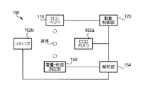
はじめに、本発明にかかる駆動波形決定装置の構成を説明する。図1は、駆動波形決定装置100の構成を示す図である。駆動波形決定装置100は、例えば、銀微粒子をC14H30(テトラデカン)溶媒に分散させた液体材料を基板の所定の位置に吐出することによって基板上に導電膜パターンを形成する液滴吐出装置の吐出ヘッドの駆動波形を決定するための装置である。
Hereinafter, embodiments of the present invention will be described with reference to the drawings.
<Configuration of drive waveform determination device>
First, the configuration of the drive waveform determination device according to the present invention will be described. FIG. 1 is a diagram illustrating a configuration of the drive
駆動制御部120は、吐出ヘッド110を駆動させるための駆動波形を吐出ヘッドに供給する。吐出ヘッド110は、圧電素子が設けられた液体充填部(図示省略)を有し、この駆動波形によって圧電素子を伸張または収縮させることによって液体充填部の要領を膨張または収縮させる。これにより、吐出ヘッド110は、液体材料を液滴化して、基板に向けて吐出する。また、吐出ヘッド110は、複数のノズルを有している。
解析部154はコンピュータ装置であり、CPU(Central Processing Unit)、ROM(Read Only Memory)、RAM(Random Access Memory)等を有し、ROMに格納されたコンピュータプログラムをCPUが実行することによって駆動波形決定装置100各部の制御を行う。
解析部154は、液滴の最適な重量、最適な吐出速度を液体材料の種類・物性値・温度と対応付けて記憶している。また、解析部154は、吐出ヘッドから吐出された液滴の重量および吐出速度が記憶されている値と一致するか否かを判定し、最適な駆動波形の決定を行う。さらに、解析部154は、決定された駆動波形を液体材料の種類・物性値・温度と対応付けて記憶する。解析部154によって行われる処理の手順については後述する。
なお、本実施形態においては、液体材料の物性値として粘度を用いるが、表面張力、接触角、密度などを用いてもよい。
The
The
The
In the present embodiment, viscosity is used as a physical property value of the liquid material, but surface tension, contact angle, density, and the like may be used.
重量・粘度測定部150は、水晶振動子に液滴が付着した際の共振周波数の変化を用いて液滴の重量を測定するQCM(Quartz Crystal Micro balance)であり、重量測定手段および物性値測定手段として機能する。なお、液体材料の物性値として表面張力、接触角、密度などを用いる場合には、物性値測定手段は、これらの物性値を測定する機能を有するものとする。
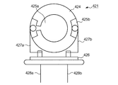
図2は、重量・粘度測定部150の構成を示す図である。重量・粘度測定部150は、センサーチップ421、周波数カウンタ422、演算部423およびパルス発生部420を主な構成要素としている。図3は、センサーチップ421の構成を示す図である。同図では、センサーチップ421の吐出ヘッド110と対向する面を示している。水晶振動子424の両面には、一対の電極425a、425bが対向して取り付けられている。絶縁体426は、導電性を有する支持体427a、427bを介して、水晶振動子424を振動自在に保持する。支持体427aは、電極425aと導通するとともに、絶縁体426に固定された端子428aと導通している。一方、支持体427bは、電極425bと導通するとともに、絶縁体426に固定された端子428bと導通している。上記の構成により、パルス発生部420から出力されたパルス信号が端子428a、428bを介してセンサーチップ421に入力されると、水晶振動子424が共振周波数にて振動する。
The weight /
FIG. 2 is a diagram illustrating a configuration of the weight /
センサーチップ421は、その一方の電極425aが吐出ヘッド110の液滴吐出面と対向するように設けられている。重量・粘度測定部420では、吐出ヘッド110から吐出された液滴が電極425aに付着すると、付着した液滴の質量を算出する。
水晶振動子は、自身に作用する外力が一定であれば一定の共振周波数にて振動するが、電極425aの表面に物質が付着して外力が変化すると、その変化量に応じて共振周波数が変化するという特性を有している。また、付着した物質が粘弾性を有する場合、水晶振動子424は、その物質の粘弾性特性値に応じて共振周波数が変化する。
The
The crystal resonator vibrates at a constant resonance frequency if the external force acting on it is constant, but when the external force changes due to the substance adhering to the surface of the
ここで、液滴の重量の測定について説明する。液滴の重量の測定は、液滴の粘弾性の影響を排除するために、液滴が乾燥して溶質が析出した後に行う。周波数カウンタ422は、析出物が付着した水晶振動子424の共振周波数を検出し、検出結果を示す信号を演算部423に供給する。ここで、水晶振動子に付着した物質の重量と共振周波数との関係は既知である。演算部423は、周波数カウンタ422から出力された共振周波数を示す信号を受け取ると、それを用いて析出物の重量を求める。そして、液体材料の濃度と析出物の重量とから乾燥前の液滴の重量を求める。なお、本実施形態においては水晶振動子を用いているが、圧電素子や磁歪素子などを用いてもよい。
なお、液滴の重量測定には以下の方法を用いてもよい。
(ア)採取法
採取法では、液滴を一定の回数だけ吐出し、容器に採取する。採取された液体の重量を電子天秤等の手段を用いて測定し、その重量を液滴数で除することによって、液滴一滴あたりの重量を求めることができる。
(イ)減量法
減量法では、液体が収容されたタンクの重量を液滴吐出前後で測定し、吐出前後の重量差を液滴数で除することによって液滴一滴あたりの重量を求める方法である。
Here, measurement of the weight of the droplet will be described. The weight of the droplet is measured after the droplet is dried and the solute is precipitated in order to eliminate the influence of the viscoelasticity of the droplet. The
The following method may be used for measuring the weight of the droplet.
(A) Collection method In the collection method, droplets are ejected a certain number of times and collected in a container. By measuring the weight of the collected liquid using a means such as an electronic balance and dividing the weight by the number of droplets, the weight per droplet can be determined.
(B) Weight loss method In the weight loss method, the weight of the tank in which the liquid is stored is measured before and after discharging the droplet, and the weight per droplet is obtained by dividing the weight difference before and after the discharge by the number of droplets. is there.
次に、液滴の粘弾性特性値の測定について説明する。本実施形態では、粘弾性特性値のうち、粘度を用いる。粘度の測定においては、粘度と減衰定数の関係を用いる。粘性を有する液体に接した物体が振動するとき、その物体の振動の振幅は液体の粘性によって減衰される。このときの時間と振幅の関係を示す物性値が減衰定数であり、粘度と減衰定数は相関関係を有している。本実施形態では、このことを利用して液滴の粘度を求める。具体的には、液体材料の粘度と減衰定数との関係を実験によって予め求めておく。ここで、粘度と減衰定数との関係が既知である液体材料については、実験によらずに既知の関係を用いてもよい。そして、液滴が水晶振動子に付着した際の振動の振幅の変化から減衰定数を求め、この減衰定数に対応する粘度を求める。 Next, measurement of the viscoelastic characteristic value of the droplet will be described. In this embodiment, viscosity is used among viscoelastic characteristic values. In measuring the viscosity, the relationship between the viscosity and the attenuation constant is used. When an object in contact with a viscous liquid vibrates, the amplitude of the vibration of the object is attenuated by the viscosity of the liquid. The physical property value showing the relationship between time and amplitude at this time is an attenuation constant, and the viscosity and the attenuation constant have a correlation. In the present embodiment, this is used to determine the viscosity of the droplet. Specifically, the relationship between the viscosity of the liquid material and the attenuation constant is obtained in advance by experiments. Here, for a liquid material in which the relationship between the viscosity and the attenuation constant is known, the known relationship may be used without depending on the experiment. Then, an attenuation constant is obtained from a change in the amplitude of vibration when the droplet adheres to the crystal resonator, and a viscosity corresponding to the attenuation constant is obtained.
上述した方法のほか、液滴の粘度と重量は以下のようにして求めることもできる。図4は、重量・粘度測定部310の構成を示す図である。重量・粘度測定部310は、上述した重量・粘度測定部150の構成に加えて、インピーダンス演算部430を有している。
水晶振動子は前述したように液滴の質量に応じた共振周波数で振動するとともに、その物質の粘度に応じて共振周波数が変化するという特性を有している。重量・粘度測定部310は、この特性を利用して、液滴の質量および粘度を求めるものである。具体的には、インピーダンス演算部430が、センサーチップ421に加えた電圧と電流との関係から、水晶振動子424の電気的なインピーダンスを求める。このインピーダンスは、共振周波数付近で大きく変化するという性質を持つ。インピーダンスの抵抗成分が最小となるときの周波数が共振周波数となり、その抵抗成分が共振抵抗値となる。インピーダンス演算部430は、水晶振動子424の共振周波数を演算により求め、共振周波数を示す信号を演算部423に供給する。また、周波数カウンタ422は、水晶振動子424の共振周波数を検出し、検出結果を示す信号を演算部423に供給する。演算部423は、インピーダンス演算部430から出力された共振抵抗値を示す信号と、周波数カウンタ422から出力された共振周波数を示す信号とを受け取ると、共振周波数、液滴の粘度および質量の関係を示す既知の計算式を用いて、液滴の粘度および質量を算出する。
In addition to the method described above, the viscosity and weight of the droplet can also be determined as follows. FIG. 4 is a diagram illustrating a configuration of the weight /
As described above, the crystal resonator vibrates at a resonance frequency corresponding to the mass of the droplet, and has a characteristic that the resonance frequency changes according to the viscosity of the substance. The weight /
次に、液滴の吐出速度の測定について説明する。吐出速度の測定は、CCD(Charge Coupled Devise)カメラ152aとストロボ152bとを用いて暗室内にて行われる。CCDカメラ152aは、飛行中の液滴を吐出方向に対して直交する方向から撮影可能な位置に設けられている。解析部154は、ストロボ152bおよびCCDカメラ152aに対して、所定の時間間隔でタイミング信号を供給する。このタイミング信号が供給されると、ストロボ152bの発光およびCCDカメラ152aによる撮影が同期して行われる。この時間間隔は、一つの液滴が吐出されてからセンサーチップ421に着弾するまでの間に複数回の撮影が行われるように設定しておく。そして、撮影された液滴の像の2点間の位置と、それらが撮影された時間間隔とを用いて、液滴の吐出速度が求められる。
Next, measurement of the droplet discharge speed will be described. The discharge speed is measured in a dark room using a CCD (Charge Coupled Devise)
上記の測定方法は、液滴の吐出速度のばらつきを調べるためにも用いられる。吐出ヘッド110には複数のノズルが設けられているが、各ノズルの寸法や出力特性には誤差がある。そのため、ノズル間で液滴一滴毎の重量のばらつきが生じる。ここで、全ノズルに同一波形を印加する駆動方法では、液滴の重量と吐出速度とは相関があることがわかっており、吐出速度のばらつきが少ない状態では、液滴一滴毎の重量のばらつきも少なくなる。
本実施形態では、この関係を利用して、各ノズルの吐出速度を測定することによって、ノズル間の吐出量のばらつきを評価する。ばらつきの評価については後述する。
The above measuring method is also used for examining variations in the discharge speed of the droplets. The
In the present embodiment, by utilizing this relationship, the discharge rate variation of each nozzle is evaluated by measuring the discharge speed of each nozzle. The evaluation of variation will be described later.
なお、吐出速度の測定には以下の方法を用いてもよい。
(ア)液滴の飛行経路上の2点を通過するようにレーザー光を出射し、光源に対面する測定部でレーザー光の強度を測定する。液滴が吐出されると、飛行中の液滴によりレーザー光が一部遮断されるから、このときのエネルギー変化を検出することによって液滴の通過時刻が求められる。そして、2点間の距離と通過時刻の時間差とから液滴の速度が求められる。
(イ)液滴の吐出時刻は駆動制御部120の設定値により既知である。また、液滴の着弾時刻は、重量・粘度測定部150における共振周波数変化が始まった時刻と同一である。
両者の時間差、および吐出ヘッド110とセンサーチップ421上面との距離とから、液滴の吐出速度を求めることができる。
The following method may be used for measuring the discharge speed.
(A) The laser beam is emitted so as to pass through two points on the flight path of the droplet, and the intensity of the laser beam is measured by a measuring unit facing the light source. When the droplets are ejected, the laser light is partially blocked by the flying droplets, and the passage time of the droplets can be obtained by detecting the energy change at this time. The speed of the droplet is obtained from the distance between the two points and the time difference between the passage times.
(A) The droplet discharge time is known from the set value of the
From the time difference between the two and the distance between the
<駆動波形の決定手順>
次に、上述の駆動波形決定装置100を用いた駆動波形の決定手順について説明する。
図5は、駆動波形決定のフローを示す図である。
最初に、駆動波形を決定する際の出発点となる基本駆動波形を決定する(ステップS1)。
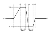
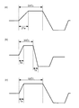
図6は、基本駆動波形の一例を示す図である。この基本駆動波形は、吐出ヘッド110の液体充填部を膨張させる期間t1〜t2、液体充填部の膨張を維持する期間t2〜t3(ホールド時間Pwh1)、液体充填部を収縮させる期間t3〜t4、液体充填部の収縮を維持する期間t4〜t5(ホールド時間Pwh2)、液体充填部の収縮を解放する期間t5〜t6、液体充填部の初期の容積を維持する期間t6〜t1から構成されている。ここで、期間t6〜t1においては中間電位VCが、期間t2〜t3においては最高電位VHが、期間t4〜t5においては最低電位VLがそれぞれ吐出ヘッドに印加される。
<Determination procedure of drive waveform>
Next, a procedure for determining a drive waveform using the drive
FIG. 5 is a diagram showing a flow of driving waveform determination.
First, a basic drive waveform that is a starting point for determining a drive waveform is determined (step S1).
FIG. 6 is a diagram illustrating an example of a basic drive waveform. This basic drive waveform includes periods t1 to t2 for expanding the liquid filling part of the
パラメータTcは以下のようにして測定される。まず、図6に示す波形の駆動電圧を吐出ヘッドに印加することによって、ある吐出速度で液滴が吐出される。この吐出速度は、駆動波形によって変化する。図7は、ホールド時間Pwh1を変化させたときの吐出速度の変化を示す図である。横軸がホールド時間Pwh1、縦軸が吐出速度vmである。同図に示されるように、ホールド時間Pwh1の長さに応じて吐出速度vmは周期的に変化する。このときの吐出速度vmの変化の周期tβ−tαがパラメータTcとなる。
次に、駆動波形を決定するために用いるもうひとつのパラメータTaについて説明する。図8は、Taを決定する際に用いる駆動波形の一例を示す図である。この駆動波形は、吐出ヘッド110の液体充填部を膨張させる期間t1〜t2、吐出ヘッド110の液体充填部の膨張を維持する期間t2〜t3、吐出ヘッド110の液体充填部を収縮させる期間t3〜t4、吐出ヘッド110の液体充填部の収縮を維持する期間t4〜t1(ホールド時間w)から構成されている。ここで、期間t1〜t2、期間t2〜t3、期間t3〜t4は同一の長さTa0を有し、期間t4〜t1は長さwを有している。長さTa0は、吐出ヘッドの設計値から予め求められ、Taを求めるための初期値として用いられる。
The parameter Tc is measured as follows. First, droplets are ejected at a certain ejection speed by applying a drive voltage having a waveform shown in FIG. 6 to the ejection head. This discharge speed varies depending on the drive waveform. FIG. 7 is a diagram illustrating a change in the discharge speed when the hold time Pwh1 is changed. The horizontal axis is the hold time Pwh1, and the vertical axis is the discharge speed vm. As shown in the figure, the discharge speed vm changes periodically according to the length of the hold time Pwh1. The change period tβ-tα of the discharge speed vm at this time is the parameter Tc.
Next, another parameter Ta used for determining the drive waveform will be described. FIG. 8 is a diagram illustrating an example of a drive waveform used when Ta is determined. This drive waveform includes a period t1 to t2 during which the liquid filling part of the
パラメータTaは以下のようにして測定される。まず、図8に示す波形の駆動電圧を吐出ヘッドに印加することによって、ある吐出速度でインクが吐出される。この吐出速度は、駆動波形によって変化する。
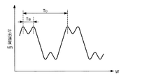
図9は、ホールド時間wを変化させたときの吐出速度vmの変化を示す図である。横軸がホールド時間w、縦軸が吐出速度である。同図に示されるように、ホールド時間wの変化に応じて吐出速度は周期的に変化する。この波形は、複数の波形が合成されたものとなっており、フーリエ解析によって各波形成分の周期を求めることができる。長い方の周期はパラメータTcに相当する。また、短い方の周期をパラメータTaとする。
Tcは上述した2つの方法のどちらを用いても求めることができるが、いずれの方法を用いてもよい。
The parameter Ta is measured as follows. First, ink is ejected at a certain ejection speed by applying a driving voltage having a waveform shown in FIG. 8 to the ejection head. This discharge speed varies depending on the drive waveform.
FIG. 9 is a diagram showing a change in the discharge speed vm when the hold time w is changed. The horizontal axis is the hold time w, and the vertical axis is the discharge speed. As shown in the figure, the discharge speed changes periodically according to the change of the hold time w. This waveform is obtained by synthesizing a plurality of waveforms, and the period of each waveform component can be obtained by Fourier analysis. The longer cycle corresponds to the parameter Tc. Further, the shorter cycle is set as the parameter Ta.
Tc can be determined using either of the two methods described above, but either method may be used.
図10は、上述のようにして求められたTcおよびTaを用いて作成された基本駆動波形の例を示す図である。同図において、(a)は基本駆動波形の第1候補、(b)は第2候補、(c)は第3候補を表す。まず、第1候補の駆動波形を用いて吐出を試行し、速度測定部152のCCDカメラ152aで撮影された画像により、液滴の吐出状態を観察する。吐出ヘッド110に設けられた複数のノズルのすべてから液滴が吐出されているならば、第1候補の駆動波形を駆動波形決定のための基本駆動波形として採用する。一方、液滴が吐出されないノズルが存在する場合には、第1候補を採用せず、第2候補の駆動波形を用いて吐出を試行する。そして、第2候補の駆動波形によってすべてのノズルから液滴が吐出されているならば、第2候補の駆動波形を基本駆動波形として採用する。第2候補の駆動波形によっても液滴が吐出されないノズルが存在する場合には、第3候補の駆動波形を基本駆動波形として採用する。
なお、基本駆動波形の決定には以下に述べる方法を用いてもよい。この方法では、まず、解析部154に、過去に求められた駆動波形を粘度と対応付けて記憶させておく。そして、重量・粘度測定部150で液滴の粘度を測定し、記憶されている波形の中から、測定された粘度に最も近い粘度に対応する波形を選択する。
FIG. 10 is a diagram showing an example of a basic drive waveform created using Tc and Ta obtained as described above. In the figure, (a) represents the first candidate of the basic drive waveform, (b) represents the second candidate, and (c) represents the third candidate. First, ejection is attempted using the drive waveform of the first candidate, and the ejection state of the droplet is observed from an image photographed by the
Note that the method described below may be used to determine the basic drive waveform. In this method, first, the driving waveform obtained in the past is stored in the
以上のようにして基本駆動波形が決定されたならば、次に波形の調整を行う。
波形の調整においては、最初に、最高電位のホールド時間Pwh1の調整を行う(ステップS2)。ホールド時間Pwh1の調整は、以下に示す方法により行う。
まず、ステップS1で選択された基本駆動波形を用いて液滴を吐出し、複数のノズルから吐出される液滴の像をCCDカメラ152aで撮影することによって、各ノズルの吐出速度を測定する。ここで、吐出速度の測定は、基本駆動波形のPwh1を幾とおりかに変化させて行う。そして、目標とする吐出速度vmからの誤差(ばらつき)をノズル毎に求め、さらにその平均値δvmを求める。そして、誤差の平均値δvmを目標吐出速度vmで除することによって、速度に対するばらつきの発生割合(相対ばらつき)δvm/vmを求める。
図11は、ホールド時間Pwh1と相対ばらつきδvm/vmとの関係を示す図である。同図に示されるように、相対ばらつきδvm/vmはホールド時間Pwh10において極小値を持つ。すなわち、最高電位のホールド時間をPwh10に設定することによって、吐出速度の相対ばらつきが最小となる。よって、Pwh10が最高電位のホールド時間の最適値となる。
If the basic drive waveform is determined as described above, the waveform is adjusted next.
In the waveform adjustment, first, the hold time Pwh1 of the highest potential is adjusted (step S2). The hold time Pwh1 is adjusted by the following method.
First, droplets are ejected using the basic drive waveform selected in step S1, and images of droplets ejected from a plurality of nozzles are taken by the
FIG. 11 is a diagram showing the relationship between the hold time Pwh1 and the relative variation δvm / vm. As shown in the figure, the relative variation δvm / vm has a minimum value in the hold time Pwh10. That is, by setting the hold time of the highest potential to Pwh10, the relative variation in the discharge speed is minimized. Therefore, Pwh10 is the optimum value for the hold time of the highest potential.
次に、最低電位のホールド時間Pwh2を調整する(ステップS3)。ホールド時間Pwh2の調整は、以下に示す方法により行う。
まず、ステップS2で決定された駆動波形を用いて液滴を吐出し、液滴の重量を測定する。ここで、重量測定は、駆動電圧の周波数を幾とおりかに変化させて行う。図12は、駆動電圧の周波数fと吐出される液滴の重量Iwとの関係を示す図である。同図に示されるように、駆動電圧の周波数fが高くなるにつれて、液滴の重量Iwが小さくなり、ある周波数を超えると急激に重量Iwが減少するという関係がある。ここで、重量Iwの最大値と周波数fが20kHzのときの重量との差をδIwとする。
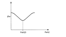
次に、ホールド時間Pwh2を幾とおりかに変化させて、上記と同様に液滴の重量を測定する。図13は、前述のδIwとホールド時間Pwh2との関係を示す図である。同図に示されるように、δIwはホールド時間Pwh2において極小値を持つ。すなわち、最低電位のホールド時間をPwh20に設定することによって、高い周波数に対しても液滴の重量の落ち込みが最も少なくなる。よって、Pwh20が最低電位のホールド時間の最適値となる。
Next, the minimum potential hold time Pwh2 is adjusted (step S3). The hold time Pwh2 is adjusted by the following method.
First, a droplet is ejected using the drive waveform determined in step S2, and the weight of the droplet is measured. Here, the weight measurement is performed by changing the frequency of the drive voltage in several ways. FIG. 12 is a diagram showing the relationship between the frequency f of the driving voltage and the weight Iw of the ejected droplet. As shown in the figure, there is a relationship that the weight Iw of the droplet decreases as the frequency f of the drive voltage increases, and the weight Iw rapidly decreases when a certain frequency is exceeded. Here, the difference between the maximum value of the weight Iw and the weight when the frequency f is 20 kHz is δIw.
Next, the hold time Pwh2 is changed in several ways, and the weight of the droplet is measured in the same manner as described above. FIG. 13 is a diagram showing the relationship between the aforementioned δIw and the hold time Pwh2. As shown in the figure, δIw has a minimum value in the hold time Pwh2. That is, by setting the minimum potential hold time to Pwh20, the drop in the weight of the droplet is minimized even at a high frequency. Therefore, Pwh20 is the optimum value for the minimum potential hold time.
なお、最低電位のホールド時間Pwh2の調整は以下に示す方法によっても可能である。図14は、液滴の重量Iwとホールド時間Pwh2との関係を示す図である。同図に示されるように、Pwh2がある範囲内にあるときは液滴が正常に吐出され、その範囲から外れた場合は吐出不良を起こすことがわかっている。この液滴が正常に吐出されるPwh2の範囲の中点をPwh20の最適値としてもよい。
以上により、駆動波形の時間軸方向の要素が決定されたことになる。これによって、上述したように、ノズル間のばらつきの抑制、周波数に対する液滴重量の安定化が図られる。これに対して、以下では、所望の液滴重量と吐出速度を得ることを目的として、電位の調整を行う。
The minimum potential hold time Pwh2 can also be adjusted by the following method. FIG. 14 is a diagram showing the relationship between the droplet weight Iw and the hold time Pwh2. As shown in the figure, it is known that when Pwh2 is within a certain range, the droplet is ejected normally, and when it is out of the range, ejection failure occurs. The midpoint of the range of Pwh2 in which the droplets are normally ejected may be set as the optimum value of Pwh20.
Thus, the elements in the time axis direction of the drive waveform are determined. Thereby, as described above, it is possible to suppress the variation between the nozzles and stabilize the droplet weight with respect to the frequency. In contrast, in the following, the potential is adjusted for the purpose of obtaining a desired droplet weight and ejection speed.
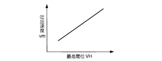
最初に最高電位VHを調整する(ステップS4)。最高電位VHの調整は、以下のようにして行う。まず、ステップS3で求められた駆動波形を用いて液滴を吐出し、液滴の吐出速度vmを測定する。ここで、最高電位VHを幾とおりかに変化させて、吐出速度vmを測定する。図15は、最高電位VHと吐出速度vmとの関係を示す図である。同図に示されるように、最高電位VHが高くなるにつれて液滴の吐出速度vmが増加する。この結果から、所望の吐出速度が得られる最高電位VHを求める。
次に、中間電位VCを調整する(ステップS5)。中間電位VCの調整は、以下のようにして行う。まず、ステップS4で求められた駆動波形を用いて液滴を吐出し、液滴の重量Iwを測定する。ここで、中間電位VCを幾とおりかに変化させて、液滴の重量Iwを測定する。図16は、中間電位VCと液滴の重量Iwとの関係を示す図である。同図に示されるように、中間電位VCが高くなるにつれて、液滴の重量Iwが増加する。なお、吐出速度vmは中間電位VCに関わらず一定である。この結果から、所望の液滴重量が得られる中間電位VCを求める。
First, the maximum potential VH is adjusted (step S4). The maximum potential VH is adjusted as follows. First, droplets are ejected using the drive waveform obtained in step S3, and the droplet ejection speed vm is measured. Here, the discharge speed vm is measured by changing the maximum potential VH in several ways. FIG. 15 is a diagram illustrating a relationship between the maximum potential VH and the discharge speed vm. As shown in the figure, the droplet ejection speed vm increases as the maximum potential VH increases. From this result, the maximum potential VH at which a desired discharge speed is obtained is obtained.
Next, the intermediate potential VC is adjusted (step S5). The adjustment of the intermediate potential VC is performed as follows. First, a droplet is ejected using the drive waveform obtained in step S4, and the weight Iw of the droplet is measured. Here, the weight Iw of the droplet is measured by changing the intermediate potential VC in several ways. FIG. 16 is a diagram showing the relationship between the intermediate potential VC and the droplet weight Iw. As shown in the figure, as the intermediate potential VC increases, the droplet weight Iw increases. The discharge speed vm is constant regardless of the intermediate potential VC. From this result, an intermediate potential VC at which a desired droplet weight can be obtained is obtained.
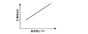
次に、最高電位VHを再調整する(ステップS6)。最高電位VHの再調整は、以下のようにして行う。まず、ステップS5で求められた駆動波形を用いて液滴を吐出し、液滴の重量Iwを測定する。ここで、最高電位VHを幾とおりからに変化させて、液滴の重量Iwを測定する。図17は、最高電位VHと液滴の重量Iwとの関係を示す図である。同図に示されるように、最高電位VHが高くなるにつれて、液滴の重量Iwが増加する。この結果から、所望の液滴重量が得られる最高電位VHを求める。
以上により、駆動波形の決定が行われる。なお、液滴の吐出状態は、液体材料の温度によっても変化するから、想定される範囲内の複数段階の温度において、上記の駆動波形決定作業を行う。そして、液体材料の種類、粘度および温度に対応付けて駆動波形を表すデータを解析部154に記憶させる。
Next, the maximum potential VH is readjusted (step S6). The readjustment of the maximum potential VH is performed as follows. First, a droplet is ejected using the drive waveform obtained in step S5, and the weight Iw of the droplet is measured. Here, the weight Iw of the droplet is measured by changing the maximum potential VH from several ways. FIG. 17 is a diagram illustrating the relationship between the maximum potential VH and the droplet weight Iw. As shown in the figure, the weight Iw of the droplet increases as the maximum potential VH increases. From this result, the maximum potential VH at which a desired droplet weight can be obtained is obtained.
Thus, the drive waveform is determined. In addition, since the discharge state of the droplet also changes depending on the temperature of the liquid material, the above-described drive waveform determination operation is performed at a plurality of stages of temperatures within an assumed range. Then, the
以上説明したように、本発明によれば、液滴吐出装置の適確な駆動波形を少ない試行で決定することができる。液滴一滴毎の重量と吐出速度が測定できるから、実際の吐出状態を反映した正確な調整が可能となる。また、液滴の粘度と駆動波形とを対応付けて記憶することにより、液滴の粘度に応じて最適な駆動波形を選択することが可能となる。 As described above, according to the present invention, it is possible to determine an appropriate driving waveform of the droplet discharge device with a small number of trials. Since the weight and discharge speed of each droplet can be measured, accurate adjustment reflecting the actual discharge state is possible. Further, by storing the viscosity of the droplet and the driving waveform in association with each other, it becomes possible to select an optimum driving waveform according to the viscosity of the droplet.
<変形例>
上述の実施形態で説明した駆動波形決定装置は一例であり、本発明は、様々な形態に変形することができる。
上述の実施形態では、駆動波形決定装置の例を示したが、この駆動波形決定装置を液滴吐出装置に組み込むこととしてもよい。図18は、液滴吐出装置の例を示す図である。液滴吐出装置10は、液滴を基板9に対して吐出するヘッド部20を備えている。ステージ12は、紙フェノールやガラス等の薄板である基板9をセットするための載置台である。
ここで、ヘッド部20はスライダ31によりx方向に移動でき、ステージ12は、スライダ32によりy方向に移動できるように構成されている。これにより、ヘッド部20と基板9との相対位置の調整が行われ、基板9の任意の位置に液滴を吐出することができる。
このような液滴吐出装置に本発明の駆動波形決定装置を組み込むことによって、生産現場において、液滴の種類に応じて最適な駆動波形を迅速に決定することが可能となり、生産効率を向上させることができる。
<Modification>
The drive waveform determination apparatus described in the above embodiment is an example, and the present invention can be modified in various forms.
In the above-described embodiment, an example of the drive waveform determination device has been described. However, the drive waveform determination device may be incorporated in the droplet discharge device. FIG. 18 is a diagram illustrating an example of a droplet discharge device. The
Here, the
By incorporating the drive waveform determination device of the present invention into such a droplet discharge device, it becomes possible to quickly determine the optimum drive waveform according to the type of droplets at the production site, thereby improving production efficiency. be able to.
また、上述の実施形態では、吐出ヘッド110に設けられた複数のノズルに同一波形の電圧を印加しているが、ノズル毎に異なる波形の電圧を印加することとしてもよい。この場合においても、上述した波形調整方法を用いることができ、ノズル毎に最適の波形を生成することができる。
また、上述の実施形態では、吐出ヘッドの液体充填部の膨張および収縮を行なわせて、液滴を吐出する駆動波形を用いて説明したが、この他に、吐出ヘッドの液体充填部の膨張およびその膨張の解放(すなわち中間電位VCに戻す)を行なわせて、液滴を吐出する駆動波形においても適用可能である。また、図6に示した駆動波形の逆位相の駆動波形においても、適用可能である。
In the above-described embodiment, the voltage having the same waveform is applied to the plurality of nozzles provided in the
In the above-described embodiment, the liquid filling portion of the ejection head is expanded and contracted, and the driving waveform for ejecting droplets is described. However, in addition to this, the expansion and contraction of the liquid filling portion of the ejection head are described. The present invention can also be applied to a drive waveform in which the expansion is released (that is, returned to the intermediate potential VC) to eject droplets. Further, the present invention can also be applied to a drive waveform having a phase opposite to that of the drive waveform shown in FIG.
上述の実施形態において、インクジェット装置としては、導電性材料を含む液滴を基板132の所定の位置に付着させる装置として説明したが、他に、着色液体の用紙印字、EL(Electro Luminescence)素子の製造、レジスト形成、液晶表示装置におけるガラス基板上のカラーフィルタ形成や液晶材料の封入、マイクロレンズアレイの製造、あるいは生体物質の測定のための液体吐出などの用途にも用いることができる。
本発明のインクジェット装置としては例えば、有機EL素子における正孔輸送性発光層または電子輸送層などの層を形成する装置、あるいは無機EL素子における蛍光発光層の層形成装置が挙げられる。また他に、本発明のインクジェット装置として、所定の導電膜パターン形成の際におけるリソグラフィ工程のレジストを塗布する装置、マイクロレンズアレイの製造工程において複数の凸部を有する原盤に光透過性材料を塗布する装置、試験管などの容器媒体に注入されたDNA(deoxyribonucleic acid)などの生体物質の種類または量を測定するための触媒を吐出する装置、あるいはその生体物質自体を試験管などの媒体に吐出する装置が挙げられる。
In the above-described embodiment, the ink jet apparatus has been described as an apparatus that attaches a droplet containing a conductive material to a predetermined position of the substrate 132. However, other than that, printing of colored liquid, EL (Electro Luminescence) element It can also be used for applications such as production, resist formation, color filter formation on a glass substrate in a liquid crystal display device, encapsulation of a liquid crystal material, production of a microlens array, or liquid discharge for measurement of biological substances.
Examples of the ink jet device of the present invention include a device for forming a layer such as a hole transporting light emitting layer or an electron transporting layer in an organic EL element, or a layer forming device for a fluorescent light emitting layer in an inorganic EL element. In addition, as an inkjet apparatus according to the present invention, an apparatus for applying a resist in a lithography process when a predetermined conductive film pattern is formed, and a light-transmitting material is applied to a master having a plurality of convex portions in a manufacturing process of a microlens array A device that discharges a catalyst for measuring the type or amount of biological material such as DNA (deoxyribonucleic acid) injected into a container medium such as a test tube, or the biological material itself is discharged into a medium such as a test tube The apparatus which performs is mentioned.
<電気光学装置および電子機器>
上述の駆動波形決定装置で決定された駆動波形が供給される液滴吐出装置により形成されたカラーフィルタを有する電気光学装置と、この電気光学装置を表示部として適用した電子機器について説明する。
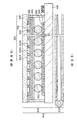
図19は、カラーフィルタを有する電気光学装置の断面図である。この図に示すように、電気光学装置640は、大略して、観察者側に向けて光を放出するバックライト機構642と、バックライト機構642から放出された光を選択的に透過させるパッシブ型液晶表示パネル644とを有している。このうち、液晶表示パネル644は、基板646と、電極648と、配向膜650と、スペーサ652と、配向膜654と、電極656と、カラーフィルタ660とを有している。カラーフィルタ660は、隔壁620からみて基板600側が上側(観察者側)に位置している。このカラーフィルタ660に含まれる赤色カラーフィルタ632R、緑色カラーフィルタ632Gおよび青色カラーフィルタ632Bは、本発明の液滴吐出装置によりパターニングされたものであり、略設計値と等しい厚みを有している。また、各カラーフィルタ632R、632G、632Bの背面側には、それらの保護を目的としたオーバーコート層658が設けられている。
スペーサ652を隔てて対向する2つの配向膜650、654の間隙には、液晶が封入されており、電極648、656により電圧が印加されると、バックライト機構642から放出された光を、各カラーフィルタ632R、632G、632Bに対応する領域毎に選択的に透過させる。
<Electro-optical device and electronic device>
An electro-optical device having a color filter formed by a droplet discharge device to which a driving waveform determined by the above-described driving waveform determining device is supplied, and an electronic apparatus to which the electro-optical device is applied as a display unit will be described.
FIG. 19 is a cross-sectional view of an electro-optical device having a color filter. As shown in this figure, the electro-
Liquid crystal is sealed in the gap between the two
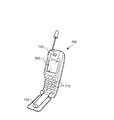
次に、図20は、電気光学装置640を搭載した携帯電話機700の外観図である。この図において、携帯電話機700は、複数の操作ボタン710の他、受話口720、送話口730とともに、電話番号などの各種情報を表示する表示部として、カラーフィルタを含む電気光学装置640を備えている。
また、携帯電話機700以外にも、本発明の液滴吐出装置を用いて製造された電気光学装置640は、コンピュータや、プロジェクタ、デジタルカメラ、ムービーカメラ、PDA(Personal Digital Assistant)、車載機器、複写機、オーディオ機器などの各種電子機器の表示部として用いることができる。
Next, FIG. 20 is an external view of a
In addition to the
100…駆動波形決定装置、110…吐出ヘッド、120…駆動制御部、150…重量・粘度測定部、152a…CCDカメラ、152b…ストロボ、154…解析部。
DESCRIPTION OF
Claims (14)
前記吐出ヘッドに駆動波形を供給する駆動制御手段と、
前記液滴の最適な重量および吐出速度を記憶する条件記憶手段と、
前記吐出ヘッドから吐出された液滴の重量を測定する重量測定手段と、
前記吐出ヘッドから吐出された液滴の吐出速度を測定する速度測定手段と、
前記駆動波形の基本形を記憶する基本駆動波形記憶手段と、
前記基本駆動波形記憶手段から基本形となる駆動波形を読み出し、前記重量測定手段で測定された重量と、前記速度測定手段で測定された吐出速度とが、前記条件記憶手段で記憶されている重量および吐出速度と一致するように当該駆動波形を調整する波形調整手段と、
前記波形調整手段により調整された駆動波形を記憶する波形記憶手段と
を有することを特徴とする駆動波形決定装置。 An ejection head comprising a liquid filling portion filled with a liquid material, and ejecting the liquid material in droplets by expanding or contracting the liquid filling portion according to a driving waveform;
Drive control means for supplying a drive waveform to the ejection head;
Condition storage means for storing the optimum weight and discharge speed of the droplet;
A weight measuring means for measuring the weight of the droplets discharged from the discharge head;
Speed measuring means for measuring the ejection speed of the droplets ejected from the ejection head;
Basic drive waveform storage means for storing the basic form of the drive waveform;
The basic driving waveform storage means reads out the basic driving waveform, and the weight measured by the weight measuring means and the discharge speed measured by the speed measuring means are the weight stored in the condition storage means and Waveform adjusting means for adjusting the drive waveform so as to coincide with the discharge speed;
And a waveform storage means for storing the drive waveform adjusted by the waveform adjustment means.
前記基本駆動波形記憶手段は、液滴の物性値に応じた複数の駆動波形を記憶し、
前記波形調整手段は、前記物性値取得手段が取得した物性値に応じた駆動波形を前記基本駆動波形記憶手段から読み出し、
前記波形記憶手段は、前記波形調整手段により調整された駆動波形を前記物性値取得手段で取得された物性値と対応付けて記憶する
ことを特徴とする請求項1に記載の駆動波形決定装置。 Having a physical property value acquiring means for acquiring a physical property value of a droplet discharged from the discharge head;
The basic drive waveform storage means stores a plurality of drive waveforms corresponding to the physical property values of the droplets,
The waveform adjustment means reads out a drive waveform corresponding to the physical property value acquired by the physical property value acquisition means from the basic drive waveform storage means,
The drive waveform determination apparatus according to claim 1, wherein the waveform storage unit stores the drive waveform adjusted by the waveform adjustment unit in association with the physical property value acquired by the physical property value acquisition unit.
前記吐出ヘッドと対向するように設けられた電極と、
前記電極表面に付着した物質の重量に応じて周波数が変化する振動子と、
前記振動子の周波数を測定する周波数カウンタと、
前記周波数カウンタで測定された前記液滴の付着前後の周波数の変化量に基づいて、前記液滴の重量を算出する算出手段と
を有することを特徴とする請求項1に記載の駆動波形決定装置。 The weight measuring means includes
An electrode provided to face the discharge head;
A vibrator whose frequency changes according to the weight of the substance attached to the electrode surface;
A frequency counter for measuring the frequency of the vibrator;
The drive waveform determination device according to claim 1, further comprising: a calculation unit that calculates a weight of the droplet based on a change amount of the frequency before and after adhesion of the droplet measured by the frequency counter. .
前記波形調整手段は、前記複数のノズルの吐出速度のばらつきを測定し、該ばらつきが最小となるように前記駆動波形の前記VHを維持するホールド時間を定める
ことを特徴とする請求項1乃至3のいずれかに記載の駆動波形決定装置。 The ejection head has a plurality of nozzles, and the driving waveform changes at least between an initial potential VC, a potential VH when the liquid filling portion is expanded, and a potential VL when the liquid filling portion is contracted. Has a waveform component,
The waveform adjusting means measures a variation in ejection speed of the plurality of nozzles, and determines a hold time for maintaining the VH of the drive waveform so that the variation is minimized. The drive waveform determination apparatus in any one of.
請求項1乃至9に記載の駆動波形決定装置と
を有し、
前記駆動制御手段は、前記駆動波形決定装置で決定された駆動波形を前記吐出ヘッドに供給する
ことを特徴とする液滴吐出装置。 A liquid filling section filled with a liquid material, and an ejection head for expanding and contracting the liquid filling section according to a change in a driving waveform to form and eject the liquid material into droplets; and a driving waveform on the ejection head. Drive control means to supply;
A drive waveform determination device according to claim 1,
The liquid droplet ejection apparatus, wherein the drive control means supplies the ejection waveform determined by the drive waveform determination apparatus to the ejection head.
Priority Applications (2)
| Application Number | Priority Date | Filing Date | Title |
|---|---|---|---|
| JP2004035541A JP2005193221A (en) | 2003-02-25 | 2004-02-12 | Driving waveform deciding device, electrooptical device and electronic equipment |
| US10/783,094 US20050104921A1 (en) | 2003-02-25 | 2004-02-23 | Drive waveform-determining device, electrooptical device, and electronic equipment |
Applications Claiming Priority (3)
| Application Number | Priority Date | Filing Date | Title |
|---|---|---|---|
| JP2003048146 | 2003-02-25 | ||
| JP2003410555 | 2003-12-09 | ||
| JP2004035541A JP2005193221A (en) | 2003-02-25 | 2004-02-12 | Driving waveform deciding device, electrooptical device and electronic equipment |
Publications (2)
| Publication Number | Publication Date |
|---|---|
| JP2005193221A true JP2005193221A (en) | 2005-07-21 |
| JP2005193221A5 JP2005193221A5 (en) | 2005-10-06 |
Family
ID=34577438
Family Applications (1)
| Application Number | Title | Priority Date | Filing Date |
|---|---|---|---|
| JP2004035541A Pending JP2005193221A (en) | 2003-02-25 | 2004-02-12 | Driving waveform deciding device, electrooptical device and electronic equipment |
Country Status (2)
| Country | Link |
|---|---|
| US (1) | US20050104921A1 (en) |
| JP (1) | JP2005193221A (en) |
Cited By (5)
| Publication number | Priority date | Publication date | Assignee | Title |
|---|---|---|---|---|
| JP2009148754A (en) * | 2007-12-24 | 2009-07-09 | Samsung Electronics Co Ltd | Apparatus for measuring mass deviation of droplets, method for measuring mass deviation of droplets using the same, pattern forming system using the same, and method of controlling pattern forming system using the same |
| JP2009226312A (en) * | 2008-03-24 | 2009-10-08 | Ulvac Japan Ltd | Ink discharge method and ink jet coating apparatus |
| JP2011192917A (en) * | 2010-03-16 | 2011-09-29 | Fujifilm Corp | Resist composition arrangement device and method of manufacturing pattern form |
| WO2012133728A1 (en) * | 2011-03-25 | 2012-10-04 | Fujifilm Corporation | Functional liquid ejection apparatus, functional liquid ejection method and imprinting system |
| JP7415402B2 (en) | 2019-09-30 | 2024-01-17 | セイコーエプソン株式会社 | Liquid injection device control method and liquid injection device |
Families Citing this family (15)
| Publication number | Priority date | Publication date | Assignee | Title |
|---|---|---|---|---|
| JP2004216596A (en) * | 2003-01-09 | 2004-08-05 | Seiko Epson Corp | Device for determining waveform, method for determining waveform, liquid drop ejector, method for ejecting liquid drop, process for depositing film, process for fabricating device, electro-optical device, and electric apparatus |
| JP2009515725A (en) * | 2005-09-15 | 2009-04-16 | フジフィルム ディマティックス, インコーポレイテッド | Waveform shaping interface |
| JP5455370B2 (en) * | 2005-10-07 | 2014-03-26 | コーニンクレッカ フィリップス エヌ ヴェ | Inkjet device for controlled positioning of a droplet of material on a substrate, method for controlled positioning of a droplet of material, method for determining alteration of a material during a printing process, and inkjet Equipment use |
| KR100717038B1 (en) * | 2005-10-10 | 2007-05-10 | 삼성전자주식회사 | Measurement device of a property of ink, inkjet printer icluding thereof, and method for sensing ink-condition |
| EP1969431A1 (en) * | 2005-12-02 | 2008-09-17 | Tennant Company | Remote configuration of mobile surface maintenance machine settings |
| KR20090113858A (en) * | 2007-01-31 | 2009-11-02 | 후지필름 디마틱스, 인크. | Printer with configurable memory |
| JP5315536B2 (en) * | 2007-02-20 | 2013-10-16 | 株式会社リコー | Image forming apparatus, head manufacturing apparatus, and method for correcting polarization of liquid discharge head |
| JP4337000B2 (en) * | 2007-03-15 | 2009-09-30 | セイコーエプソン株式会社 | Liquid ejecting head, control method therefor, and printer |
| US8579397B2 (en) * | 2008-09-05 | 2013-11-12 | Fujifilm Dimatix, Inc. | Jet performance |
| GB2553492A (en) | 2016-06-30 | 2018-03-14 | Xaar Technology Ltd | Droplet deposition head and method of providing adjustment data therefor |
| DE102017100702A1 (en) | 2017-01-16 | 2018-07-19 | Marco Systemanalyse Und Entwicklung Gmbh | Device for monitoring dosing devices |
| JP7346847B2 (en) * | 2019-02-28 | 2023-09-20 | ブラザー工業株式会社 | Droplet discharge device |
| JP2021115727A (en) * | 2020-01-23 | 2021-08-10 | セイコーエプソン株式会社 | Liquid discharge method, driving pulse determination program and liquid discharge device |
| JP2021115731A (en) * | 2020-01-23 | 2021-08-10 | セイコーエプソン株式会社 | Liquid discharge method, driving pulse determination program and liquid discharge device |
| JP2021115732A (en) * | 2020-01-23 | 2021-08-10 | セイコーエプソン株式会社 | Liquid discharge method, driving pulse determination program and liquid discharge device |
Family Cites Families (19)
| Publication number | Priority date | Publication date | Assignee | Title |
|---|---|---|---|---|
| JPH0729421B2 (en) * | 1987-04-24 | 1995-04-05 | 松下電器産業株式会社 | Ink jet printer |
| US5266098A (en) * | 1992-01-07 | 1993-11-30 | Massachusetts Institute Of Technology | Production of charged uniformly sized metal droplets |
| US5502468A (en) * | 1992-12-28 | 1996-03-26 | Tektronix, Inc. | Ink jet print head drive with normalization |
| US5502467A (en) * | 1994-03-07 | 1996-03-26 | Spectra, Inc. | Ink jet printhead with ink viscosity control |
| WO1998046432A1 (en) * | 1997-04-16 | 1998-10-22 | Seiko Epson Corporation | Method of driving ink jet recording head |
| KR20000044155A (en) * | 1998-12-30 | 2000-07-15 | 이형도 | Method for optimizing input driving signal for shape-memory alloy ink jet head, and apparatus and method for preventing overheating |
| JP2000326511A (en) * | 1999-05-18 | 2000-11-28 | Nec Corp | Driving method for ink jet recording head and circuit thereof |
| CN1274509C (en) * | 1999-09-21 | 2006-09-13 | 松下电器产业株式会社 | Ink-jet head and ink-jet type recording apparatus |
| EP1120255A3 (en) * | 2000-01-28 | 2002-01-30 | Seiko Epson Corporation | Generation of driving waveforms to actuate driving elements of print head |
| JP2002273912A (en) * | 2000-04-18 | 2002-09-25 | Seiko Epson Corp | Ink jet recording device |
| US6998230B1 (en) * | 2000-04-26 | 2006-02-14 | Agilent Technologies, Inc. | Array fabrication with drop detection |
| US6431376B1 (en) * | 2000-06-08 | 2002-08-13 | White Systems, Inc. | Storage bin assembly having unitary side and backwall supports |
| ATE380662T1 (en) * | 2000-10-06 | 2007-12-15 | Seiko Epson Corp | METHOD FOR DRIVING AN INKJET RECORDING HEAD AND CORRESPONDING INKJET RECORDING DEVICE |
| US6783210B2 (en) * | 2001-07-05 | 2004-08-31 | Seiko Epson Corporation | Ink jet recording apparatus and method of driving the same |
| US6561614B1 (en) * | 2001-10-30 | 2003-05-13 | Hewlett-Packard Company | Ink system characteristic identification |
| JP2003159786A (en) * | 2001-11-28 | 2003-06-03 | Seiko Epson Corp | Ejection method and its apparatus, electro-optic device, method and apparatus for manufacturing the device, color filter, method and apparatus for manufacturing the filter, device with substrate, and method and apparatus for manufacturing the device |
| US6843548B2 (en) * | 2002-01-11 | 2005-01-18 | Konica Corporation | Ink-jet printer |
| JP3687649B2 (en) * | 2002-01-15 | 2005-08-24 | セイコーエプソン株式会社 | Method for measuring natural vibration period of liquid ejecting head, natural vibration period measuring apparatus, liquid ejecting head, and liquid ejecting apparatus |
| JP2003305831A (en) * | 2002-04-15 | 2003-10-28 | Sharp Corp | Inkjet printer |
-
2004
- 2004-02-12 JP JP2004035541A patent/JP2005193221A/en active Pending
- 2004-02-23 US US10/783,094 patent/US20050104921A1/en not_active Abandoned
Cited By (6)
| Publication number | Priority date | Publication date | Assignee | Title |
|---|---|---|---|---|
| JP2009148754A (en) * | 2007-12-24 | 2009-07-09 | Samsung Electronics Co Ltd | Apparatus for measuring mass deviation of droplets, method for measuring mass deviation of droplets using the same, pattern forming system using the same, and method of controlling pattern forming system using the same |
| KR101339987B1 (en) | 2007-12-24 | 2013-12-10 | 삼성전자주식회사 | Apparatus for measureing drop mass deviation and controlling method of thereof and pattern forming system using thereof and controlling method of pattern forming system using thereof |
| JP2009226312A (en) * | 2008-03-24 | 2009-10-08 | Ulvac Japan Ltd | Ink discharge method and ink jet coating apparatus |
| JP2011192917A (en) * | 2010-03-16 | 2011-09-29 | Fujifilm Corp | Resist composition arrangement device and method of manufacturing pattern form |
| WO2012133728A1 (en) * | 2011-03-25 | 2012-10-04 | Fujifilm Corporation | Functional liquid ejection apparatus, functional liquid ejection method and imprinting system |
| JP7415402B2 (en) | 2019-09-30 | 2024-01-17 | セイコーエプソン株式会社 | Liquid injection device control method and liquid injection device |
Also Published As
| Publication number | Publication date |
|---|---|
| US20050104921A1 (en) | 2005-05-19 |
Similar Documents
| Publication | Publication Date | Title |
|---|---|---|
| JP2005193221A (en) | Driving waveform deciding device, electrooptical device and electronic equipment | |
| KR100563411B1 (en) | Driving waveform determining device, electro-optical device and electronic equipment | |
| US7108348B2 (en) | Droplet ejecting apparatus and ejection abnormality detecting/determining method for a droplet ejecting head | |
| KR100555198B1 (en) | Waveform determining device, waveform determining method, droplet ejecting device, droplet ejecting method, film forming method, device manufacturing method, electronic optical device, and electronic device | |
| US7328961B2 (en) | Droplet ejection apparatus and method of judging ejection failure in droplet ejection heads | |
| US7393553B2 (en) | Droplet information measuring method and apparatus therefor, film pattern forming method, device manufacturing method, droplet discharge apparatus, electro-optical apparatus, and electronic apparatus | |
| US9199450B2 (en) | Liquid discharge apparatus and residual vibration detection method | |
| JP2018524213A (en) | Method for operating an inkjet printhead | |
| US20040239727A1 (en) | Droplet ejecting device, electronic optical device, electronic device, manufacturing method for electronic optical device, and ejection control method for droplet ejecting device | |
| US7341325B2 (en) | Droplet ejection apparatus and method of detecting ejection failure in droplet ejection heads | |
| JP2006167534A (en) | Measuring method of amount of liquid droplet, method for optimizing driving signal of liquid droplet discharging head, and apparatus for discharging liquid droplet | |
| JP2004223914A (en) | Manufacturing method for liquid droplet ejecting device, electro-optical device, electronic device, and electro-optical device using liquid droplet ejecting device, and drying suppression method for liquid droplet ejecting head | |
| JP2007098691A (en) | Liquid jet head, liquid jet device and method for manufacturing the same | |
| JP3705281B2 (en) | Droplet information measuring method, film pattern forming method, film pattern manufacturing apparatus, device manufacturing method, electro-optical apparatus manufacturing method, and electronic apparatus manufacturing method | |
| JP5994128B2 (en) | Discharge device and control method of discharge device | |
| JP2002200752A (en) | Imaging apparatus | |
| JP3687664B2 (en) | Droplet information measuring device, droplet discharge device, film pattern forming method, device manufacturing method, electro-optical device manufacturing method, and electronic device manufacturing method | |
| JP2005262450A (en) | Inkjet applicator | |
| JP2005061871A (en) | Droplet weight measurement method, droplet discharging apparatus, method for manufacturing electrooptical device, electrooptical device, and electronic equipment | |
| JP2005061870A (en) | Droplet weight measuring apparatus, droplet discharging apparatus, method for measuring droplet weight, method for manufacturing electrooptical device, electrooptical device, and electronic equipment | |
| WO2004076186A1 (en) | Liquid drop ejector and method for judging abnormal ejection of liquid drop ejection head |
Legal Events
| Date | Code | Title | Description |
|---|---|---|---|
| A521 | Request for written amendment filed |
Free format text: JAPANESE INTERMEDIATE CODE: A523 Effective date: 20050819 |
|
| A621 | Written request for application examination |
Free format text: JAPANESE INTERMEDIATE CODE: A621 Effective date: 20050819 |
|
| A871 | Explanation of circumstances concerning accelerated examination |
Free format text: JAPANESE INTERMEDIATE CODE: A871 Effective date: 20050819 |
|
| A975 | Report on accelerated examination |
Free format text: JAPANESE INTERMEDIATE CODE: A971005 Effective date: 20050916 |
|
| A131 | Notification of reasons for refusal |
Free format text: JAPANESE INTERMEDIATE CODE: A131 Effective date: 20051025 |
|
| A521 | Request for written amendment filed |
Free format text: JAPANESE INTERMEDIATE CODE: A523 Effective date: 20051222 |
|
| A131 | Notification of reasons for refusal |
Free format text: JAPANESE INTERMEDIATE CODE: A131 Effective date: 20060228 |
|
| A521 | Request for written amendment filed |
Free format text: JAPANESE INTERMEDIATE CODE: A523 Effective date: 20060424 |
|
| A02 | Decision of refusal |
Free format text: JAPANESE INTERMEDIATE CODE: A02 Effective date: 20060627 |