EP2328193A2 - Piezoelectric ceramic, method for making the same, piezoelectric element, liquid discharge head, and ultrasonic motor - Google Patents
Piezoelectric ceramic, method for making the same, piezoelectric element, liquid discharge head, and ultrasonic motor Download PDFInfo
- Publication number
- EP2328193A2 EP2328193A2 EP20100014517 EP10014517A EP2328193A2 EP 2328193 A2 EP2328193 A2 EP 2328193A2 EP 20100014517 EP20100014517 EP 20100014517 EP 10014517 A EP10014517 A EP 10014517A EP 2328193 A2 EP2328193 A2 EP 2328193A2
- Authority
- EP
- European Patent Office
- Prior art keywords
- crystal grains
- piezoelectric ceramic
- piezoelectric
- barium titanate
- mass
- Prior art date
- Legal status (The legal status is an assumption and is not a legal conclusion. Google has not performed a legal analysis and makes no representation as to the accuracy of the status listed.)
- Granted
Links
- 239000000919 ceramic Substances 0.000 title claims abstract description 153
- 238000000034 method Methods 0.000 title claims description 29
- 239000007788 liquid Substances 0.000 title claims description 28
- 239000013078 crystal Substances 0.000 claims abstract description 174
- 229910002113 barium titanate Inorganic materials 0.000 claims abstract description 86
- JRPBQTZRNDNNOP-UHFFFAOYSA-N barium titanate Chemical compound [Ba+2].[Ba+2].[O-][Ti]([O-])([O-])[O-] JRPBQTZRNDNNOP-UHFFFAOYSA-N 0.000 claims abstract description 85
- 239000011572 manganese Substances 0.000 claims abstract description 56
- PWHULOQIROXLJO-UHFFFAOYSA-N Manganese Chemical compound [Mn] PWHULOQIROXLJO-UHFFFAOYSA-N 0.000 claims abstract description 54
- 229910052748 manganese Inorganic materials 0.000 claims abstract description 54
- 239000002245 particle Substances 0.000 claims description 84
- 229910052751 metal Inorganic materials 0.000 claims description 32
- 239000002184 metal Substances 0.000 claims description 32
- 238000005245 sintering Methods 0.000 claims description 27
- RKTYLMNFRDHKIL-UHFFFAOYSA-N copper;5,10,15,20-tetraphenylporphyrin-22,24-diide Chemical compound [Cu+2].C1=CC(C(=C2C=CC([N-]2)=C(C=2C=CC=CC=2)C=2C=CC(N=2)=C(C=2C=CC=CC=2)C2=CC=C3[N-]2)C=2C=CC=CC=2)=NC1=C3C1=CC=CC=C1 RKTYLMNFRDHKIL-UHFFFAOYSA-N 0.000 claims description 15
- 239000000203 mixture Substances 0.000 claims description 10
- 230000000052 comparative effect Effects 0.000 description 26
- 239000000843 powder Substances 0.000 description 25
- 238000004519 manufacturing process Methods 0.000 description 19
- 239000002994 raw material Substances 0.000 description 14
- 230000001965 increasing effect Effects 0.000 description 10
- 239000000126 substance Substances 0.000 description 9
- 239000000463 material Substances 0.000 description 8
- 238000012545 processing Methods 0.000 description 8
- 150000002739 metals Chemical class 0.000 description 7
- 239000011575 calcium Substances 0.000 description 6
- 230000000694 effects Effects 0.000 description 5
- 229910052451 lead zirconate titanate Inorganic materials 0.000 description 5
- 239000012071 phase Substances 0.000 description 5
- 239000011164 primary particle Substances 0.000 description 5
- 239000010936 titanium Substances 0.000 description 5
- OYPRJOBELJOOCE-UHFFFAOYSA-N Calcium Chemical compound [Ca] OYPRJOBELJOOCE-UHFFFAOYSA-N 0.000 description 4
- XUIMIQQOPSSXEZ-UHFFFAOYSA-N Silicon Chemical compound [Si] XUIMIQQOPSSXEZ-UHFFFAOYSA-N 0.000 description 4
- 229910052791 calcium Inorganic materials 0.000 description 4
- 238000010438 heat treatment Methods 0.000 description 4
- 239000012535 impurity Substances 0.000 description 4
- 239000011133 lead Substances 0.000 description 4
- 238000001000 micrograph Methods 0.000 description 4
- 238000002156 mixing Methods 0.000 description 4
- 229910052710 silicon Inorganic materials 0.000 description 4
- 239000010703 silicon Substances 0.000 description 4
- XEEYBQQBJWHFJM-UHFFFAOYSA-N Iron Chemical compound [Fe] XEEYBQQBJWHFJM-UHFFFAOYSA-N 0.000 description 3
- 238000011156 evaluation Methods 0.000 description 3
- UOGMEBQRZBEZQT-UHFFFAOYSA-L manganese(2+);diacetate Chemical compound [Mn+2].CC([O-])=O.CC([O-])=O UOGMEBQRZBEZQT-UHFFFAOYSA-L 0.000 description 3
- WPBNNNQJVZRUHP-UHFFFAOYSA-L manganese(2+);methyl n-[[2-(methoxycarbonylcarbamothioylamino)phenyl]carbamothioyl]carbamate;n-[2-(sulfidocarbothioylamino)ethyl]carbamodithioate Chemical compound [Mn+2].[S-]C(=S)NCCNC([S-])=S.COC(=O)NC(=S)NC1=CC=CC=C1NC(=S)NC(=O)OC WPBNNNQJVZRUHP-UHFFFAOYSA-L 0.000 description 3
- 239000011812 mixed powder Substances 0.000 description 3
- 239000007787 solid Substances 0.000 description 3
- 238000002441 X-ray diffraction Methods 0.000 description 2
- 229910052782 aluminium Inorganic materials 0.000 description 2
- 238000004458 analytical method Methods 0.000 description 2
- 229910052788 barium Inorganic materials 0.000 description 2
- 150000001553 barium compounds Chemical class 0.000 description 2
- QVQLCTNNEUAWMS-UHFFFAOYSA-N barium oxide Chemical compound [Ba]=O QVQLCTNNEUAWMS-UHFFFAOYSA-N 0.000 description 2
- 239000011230 binding agent Substances 0.000 description 2
- 229910052796 boron Inorganic materials 0.000 description 2
- AOWKSNWVBZGMTJ-UHFFFAOYSA-N calcium titanate Chemical compound [Ca+2].[O-][Ti]([O-])=O AOWKSNWVBZGMTJ-UHFFFAOYSA-N 0.000 description 2
- 230000007423 decrease Effects 0.000 description 2
- 230000003247 decreasing effect Effects 0.000 description 2
- 230000002950 deficient Effects 0.000 description 2
- 238000010304 firing Methods 0.000 description 2
- 229910052737 gold Inorganic materials 0.000 description 2
- 239000010931 gold Substances 0.000 description 2
- AMWRITDGCCNYAT-UHFFFAOYSA-L hydroxy(oxo)manganese;manganese Chemical compound [Mn].O[Mn]=O.O[Mn]=O AMWRITDGCCNYAT-UHFFFAOYSA-L 0.000 description 2
- 238000001095 inductively coupled plasma mass spectrometry Methods 0.000 description 2
- 229910052742 iron Inorganic materials 0.000 description 2
- 230000014759 maintenance of location Effects 0.000 description 2
- NUJOXMJBOLGQSY-UHFFFAOYSA-N manganese dioxide Chemical compound O=[Mn]=O NUJOXMJBOLGQSY-UHFFFAOYSA-N 0.000 description 2
- PPNAOCWZXJOHFK-UHFFFAOYSA-N manganese(2+);oxygen(2-) Chemical compound [O-2].[Mn+2] PPNAOCWZXJOHFK-UHFFFAOYSA-N 0.000 description 2
- VASIZKWUTCETSD-UHFFFAOYSA-N manganese(II) oxide Inorganic materials [Mn]=O VASIZKWUTCETSD-UHFFFAOYSA-N 0.000 description 2
- 239000004570 mortar (masonry) Substances 0.000 description 2
- 230000010287 polarization Effects 0.000 description 2
- 238000005498 polishing Methods 0.000 description 2
- 230000000717 retained effect Effects 0.000 description 2
- 150000003839 salts Chemical group 0.000 description 2
- 239000011163 secondary particle Substances 0.000 description 2
- 239000007921 spray Substances 0.000 description 2
- 238000004544 sputter deposition Methods 0.000 description 2
- 229910052712 strontium Inorganic materials 0.000 description 2
- 238000006467 substitution reaction Methods 0.000 description 2
- 229910052718 tin Inorganic materials 0.000 description 2
- 229910052719 titanium Inorganic materials 0.000 description 2
- 150000003609 titanium compounds Chemical class 0.000 description 2
- ZOXJGFHDIHLPTG-UHFFFAOYSA-N Boron Chemical compound [B] ZOXJGFHDIHLPTG-UHFFFAOYSA-N 0.000 description 1
- 239000004215 Carbon black (E152) Substances 0.000 description 1
- 229910018866 La0.5Li0.5 Inorganic materials 0.000 description 1
- OAICVXFJPJFONN-UHFFFAOYSA-N Phosphorus Chemical compound [P] OAICVXFJPJFONN-UHFFFAOYSA-N 0.000 description 1
- 239000004372 Polyvinyl alcohol Substances 0.000 description 1
- 239000004830 Super Glue Substances 0.000 description 1
- 229910010252 TiO3 Inorganic materials 0.000 description 1
- ATJFFYVFTNAWJD-UHFFFAOYSA-N Tin Chemical compound [Sn] ATJFFYVFTNAWJD-UHFFFAOYSA-N 0.000 description 1
- GWEVSGVZZGPLCZ-UHFFFAOYSA-N Titan oxide Chemical compound O=[Ti]=O GWEVSGVZZGPLCZ-UHFFFAOYSA-N 0.000 description 1
- RTAQQCXQSZGOHL-UHFFFAOYSA-N Titanium Chemical compound [Ti] RTAQQCXQSZGOHL-UHFFFAOYSA-N 0.000 description 1
- 239000000853 adhesive Substances 0.000 description 1
- 230000001070 adhesive effect Effects 0.000 description 1
- 230000002411 adverse Effects 0.000 description 1
- 238000005054 agglomeration Methods 0.000 description 1
- 230000002776 aggregation Effects 0.000 description 1
- XAGFODPZIPBFFR-UHFFFAOYSA-N aluminium Chemical compound [Al] XAGFODPZIPBFFR-UHFFFAOYSA-N 0.000 description 1
- -1 barium alkoxides Chemical class 0.000 description 1
- DSAJWYNOEDNPEQ-UHFFFAOYSA-N barium atom Chemical compound [Ba] DSAJWYNOEDNPEQ-UHFFFAOYSA-N 0.000 description 1
- GXUARMXARIJAFV-UHFFFAOYSA-L barium oxalate Chemical compound [Ba+2].[O-]C(=O)C([O-])=O GXUARMXARIJAFV-UHFFFAOYSA-L 0.000 description 1
- 229940094800 barium oxalate Drugs 0.000 description 1
- QKYBEKAEVQPNIN-UHFFFAOYSA-N barium(2+);oxido(oxo)alumane Chemical compound [Ba+2].[O-][Al]=O.[O-][Al]=O QKYBEKAEVQPNIN-UHFFFAOYSA-N 0.000 description 1
- AYJRCSIUFZENHW-DEQYMQKBSA-L barium(2+);oxomethanediolate Chemical compound [Ba+2].[O-][14C]([O-])=O AYJRCSIUFZENHW-DEQYMQKBSA-L 0.000 description 1
- 239000011324 bead Substances 0.000 description 1
- 230000005540 biological transmission Effects 0.000 description 1
- JXDXDSKXFRTAPA-UHFFFAOYSA-N calcium;barium(2+);oxygen(2-);titanium(4+) Chemical compound [O-2].[Ca+2].[Ti+4].[Ba+2] JXDXDSKXFRTAPA-UHFFFAOYSA-N 0.000 description 1
- 229910010293 ceramic material Inorganic materials 0.000 description 1
- 229910052804 chromium Inorganic materials 0.000 description 1
- 238000007906 compression Methods 0.000 description 1
- 229910052802 copper Inorganic materials 0.000 description 1
- 230000008878 coupling Effects 0.000 description 1
- 238000010168 coupling process Methods 0.000 description 1
- 238000005859 coupling reaction Methods 0.000 description 1
- 238000005336 cracking Methods 0.000 description 1
- 238000001739 density measurement Methods 0.000 description 1
- 230000006866 deterioration Effects 0.000 description 1
- 238000006073 displacement reaction Methods 0.000 description 1
- 238000009826 distribution Methods 0.000 description 1
- BXKDSDJJOVIHMX-UHFFFAOYSA-N edrophonium chloride Chemical compound [Cl-].CC[N+](C)(C)C1=CC=CC(O)=C1 BXKDSDJJOVIHMX-UHFFFAOYSA-N 0.000 description 1
- 238000005485 electric heating Methods 0.000 description 1
- 238000005430 electron energy loss spectroscopy Methods 0.000 description 1
- 230000002708 enhancing effect Effects 0.000 description 1
- 229920006332 epoxy adhesive Polymers 0.000 description 1
- FGBJXOREULPLGL-UHFFFAOYSA-N ethyl cyanoacrylate Chemical compound CCOC(=O)C(=C)C#N FGBJXOREULPLGL-UHFFFAOYSA-N 0.000 description 1
- 230000001747 exhibiting effect Effects 0.000 description 1
- 229910052732 germanium Inorganic materials 0.000 description 1
- GNPVGFCGXDBREM-UHFFFAOYSA-N germanium atom Chemical compound [Ge] GNPVGFCGXDBREM-UHFFFAOYSA-N 0.000 description 1
- 239000011521 glass Substances 0.000 description 1
- PCHJSUWPFVWCPO-UHFFFAOYSA-N gold Chemical compound [Au] PCHJSUWPFVWCPO-UHFFFAOYSA-N 0.000 description 1
- 229910052735 hafnium Inorganic materials 0.000 description 1
- VBJZVLUMGGDVMO-UHFFFAOYSA-N hafnium atom Chemical compound [Hf] VBJZVLUMGGDVMO-UHFFFAOYSA-N 0.000 description 1
- 238000001513 hot isostatic pressing Methods 0.000 description 1
- 229930195733 hydrocarbon Natural products 0.000 description 1
- 150000002430 hydrocarbons Chemical class 0.000 description 1
- 229910052738 indium Inorganic materials 0.000 description 1
- 150000002500 ions Chemical group 0.000 description 1
- 229910052741 iridium Inorganic materials 0.000 description 1
- 230000001678 irradiating effect Effects 0.000 description 1
- HFGPZNIAWCZYJU-UHFFFAOYSA-N lead zirconate titanate Chemical compound [O-2].[O-2].[O-2].[O-2].[O-2].[Ti+4].[Zr+4].[Pb+2] HFGPZNIAWCZYJU-UHFFFAOYSA-N 0.000 description 1
- 239000007791 liquid phase Substances 0.000 description 1
- 229940071125 manganese acetate Drugs 0.000 description 1
- 150000002697 manganese compounds Chemical class 0.000 description 1
- 238000005259 measurement Methods 0.000 description 1
- 230000028161 membrane depolarization Effects 0.000 description 1
- 239000007769 metal material Substances 0.000 description 1
- 238000000386 microscopy Methods 0.000 description 1
- 238000009768 microwave sintering Methods 0.000 description 1
- 238000012986 modification Methods 0.000 description 1
- 230000004048 modification Effects 0.000 description 1
- 239000002086 nanomaterial Substances 0.000 description 1
- 239000002105 nanoparticle Substances 0.000 description 1
- 229910052759 nickel Inorganic materials 0.000 description 1
- 229910052758 niobium Inorganic materials 0.000 description 1
- 239000010955 niobium Substances 0.000 description 1
- GUCVJGMIXFAOAE-UHFFFAOYSA-N niobium atom Chemical compound [Nb] GUCVJGMIXFAOAE-UHFFFAOYSA-N 0.000 description 1
- 230000006911 nucleation Effects 0.000 description 1
- 238000010899 nucleation Methods 0.000 description 1
- 239000003921 oil Substances 0.000 description 1
- 230000003287 optical effect Effects 0.000 description 1
- 238000012856 packing Methods 0.000 description 1
- 229910052763 palladium Inorganic materials 0.000 description 1
- 238000005191 phase separation Methods 0.000 description 1
- 239000011574 phosphorus Substances 0.000 description 1
- 229910052698 phosphorus Inorganic materials 0.000 description 1
- 229910052697 platinum Inorganic materials 0.000 description 1
- 238000013001 point bending Methods 0.000 description 1
- 229920002451 polyvinyl alcohol Polymers 0.000 description 1
- 239000002243 precursor Substances 0.000 description 1
- 238000003825 pressing Methods 0.000 description 1
- 230000008569 process Effects 0.000 description 1
- 230000000750 progressive effect Effects 0.000 description 1
- VSZWPYCFIRKVQL-UHFFFAOYSA-N selanylidenegallium;selenium Chemical compound [Se].[Se]=[Ga].[Se]=[Ga] VSZWPYCFIRKVQL-UHFFFAOYSA-N 0.000 description 1
- 229920002545 silicone oil Polymers 0.000 description 1
- 229910052709 silver Inorganic materials 0.000 description 1
- 239000002002 slurry Substances 0.000 description 1
- 238000001694 spray drying Methods 0.000 description 1
- CIOAGBVUUVVLOB-UHFFFAOYSA-N strontium atom Chemical compound [Sr] CIOAGBVUUVVLOB-UHFFFAOYSA-N 0.000 description 1
- 229910052715 tantalum Inorganic materials 0.000 description 1
- 238000012360 testing method Methods 0.000 description 1
- 239000010409 thin film Substances 0.000 description 1
- OGIDPMRJRNCKJF-UHFFFAOYSA-N titanium oxide Inorganic materials [Ti]=O OGIDPMRJRNCKJF-UHFFFAOYSA-N 0.000 description 1
- 238000007740 vapor deposition Methods 0.000 description 1
- 238000004876 x-ray fluorescence Methods 0.000 description 1
Images


Classifications
-
- C—CHEMISTRY; METALLURGY
- C04—CEMENTS; CONCRETE; ARTIFICIAL STONE; CERAMICS; REFRACTORIES
- C04B—LIME, MAGNESIA; SLAG; CEMENTS; COMPOSITIONS THEREOF, e.g. MORTARS, CONCRETE OR LIKE BUILDING MATERIALS; ARTIFICIAL STONE; CERAMICS; REFRACTORIES; TREATMENT OF NATURAL STONE
- C04B35/00—Shaped ceramic products characterised by their composition; Ceramics compositions; Processing powders of inorganic compounds preparatory to the manufacturing of ceramic products
- C04B35/01—Shaped ceramic products characterised by their composition; Ceramics compositions; Processing powders of inorganic compounds preparatory to the manufacturing of ceramic products based on oxide ceramics
- C04B35/46—Shaped ceramic products characterised by their composition; Ceramics compositions; Processing powders of inorganic compounds preparatory to the manufacturing of ceramic products based on oxide ceramics based on titanium oxides or titanates
- C04B35/462—Shaped ceramic products characterised by their composition; Ceramics compositions; Processing powders of inorganic compounds preparatory to the manufacturing of ceramic products based on oxide ceramics based on titanium oxides or titanates based on titanates
- C04B35/465—Shaped ceramic products characterised by their composition; Ceramics compositions; Processing powders of inorganic compounds preparatory to the manufacturing of ceramic products based on oxide ceramics based on titanium oxides or titanates based on titanates based on alkaline earth metal titanates
- C04B35/468—Shaped ceramic products characterised by their composition; Ceramics compositions; Processing powders of inorganic compounds preparatory to the manufacturing of ceramic products based on oxide ceramics based on titanium oxides or titanates based on titanates based on alkaline earth metal titanates based on barium titanates
- C04B35/4682—Shaped ceramic products characterised by their composition; Ceramics compositions; Processing powders of inorganic compounds preparatory to the manufacturing of ceramic products based on oxide ceramics based on titanium oxides or titanates based on titanates based on alkaline earth metal titanates based on barium titanates based on BaTiO3 perovskite phase
-
- H—ELECTRICITY
- H10—SEMICONDUCTOR DEVICES; ELECTRIC SOLID-STATE DEVICES NOT OTHERWISE PROVIDED FOR
- H10N—ELECTRIC SOLID-STATE DEVICES NOT OTHERWISE PROVIDED FOR
- H10N30/00—Piezoelectric or electrostrictive devices
- H10N30/80—Constructional details
- H10N30/85—Piezoelectric or electrostrictive active materials
- H10N30/853—Ceramic compositions
- H10N30/8536—Alkaline earth metal based oxides, e.g. barium titanates
-
- C—CHEMISTRY; METALLURGY
- C04—CEMENTS; CONCRETE; ARTIFICIAL STONE; CERAMICS; REFRACTORIES
- C04B—LIME, MAGNESIA; SLAG; CEMENTS; COMPOSITIONS THEREOF, e.g. MORTARS, CONCRETE OR LIKE BUILDING MATERIALS; ARTIFICIAL STONE; CERAMICS; REFRACTORIES; TREATMENT OF NATURAL STONE
- C04B35/00—Shaped ceramic products characterised by their composition; Ceramics compositions; Processing powders of inorganic compounds preparatory to the manufacturing of ceramic products
- C04B35/01—Shaped ceramic products characterised by their composition; Ceramics compositions; Processing powders of inorganic compounds preparatory to the manufacturing of ceramic products based on oxide ceramics
- C04B35/46—Shaped ceramic products characterised by their composition; Ceramics compositions; Processing powders of inorganic compounds preparatory to the manufacturing of ceramic products based on oxide ceramics based on titanium oxides or titanates
- C04B35/462—Shaped ceramic products characterised by their composition; Ceramics compositions; Processing powders of inorganic compounds preparatory to the manufacturing of ceramic products based on oxide ceramics based on titanium oxides or titanates based on titanates
- C04B35/465—Shaped ceramic products characterised by their composition; Ceramics compositions; Processing powders of inorganic compounds preparatory to the manufacturing of ceramic products based on oxide ceramics based on titanium oxides or titanates based on titanates based on alkaline earth metal titanates
- C04B35/468—Shaped ceramic products characterised by their composition; Ceramics compositions; Processing powders of inorganic compounds preparatory to the manufacturing of ceramic products based on oxide ceramics based on titanium oxides or titanates based on titanates based on alkaline earth metal titanates based on barium titanates
-
- C—CHEMISTRY; METALLURGY
- C04—CEMENTS; CONCRETE; ARTIFICIAL STONE; CERAMICS; REFRACTORIES
- C04B—LIME, MAGNESIA; SLAG; CEMENTS; COMPOSITIONS THEREOF, e.g. MORTARS, CONCRETE OR LIKE BUILDING MATERIALS; ARTIFICIAL STONE; CERAMICS; REFRACTORIES; TREATMENT OF NATURAL STONE
- C04B35/00—Shaped ceramic products characterised by their composition; Ceramics compositions; Processing powders of inorganic compounds preparatory to the manufacturing of ceramic products
- C04B35/622—Forming processes; Processing powders of inorganic compounds preparatory to the manufacturing of ceramic products
- C04B35/626—Preparing or treating the powders individually or as batches ; preparing or treating macroscopic reinforcing agents for ceramic products, e.g. fibres; mechanical aspects section B
- C04B35/62605—Treating the starting powders individually or as mixtures
- C04B35/62645—Thermal treatment of powders or mixtures thereof other than sintering
- C04B35/62655—Drying, e.g. freeze-drying, spray-drying, microwave or supercritical drying
-
- C—CHEMISTRY; METALLURGY
- C04—CEMENTS; CONCRETE; ARTIFICIAL STONE; CERAMICS; REFRACTORIES
- C04B—LIME, MAGNESIA; SLAG; CEMENTS; COMPOSITIONS THEREOF, e.g. MORTARS, CONCRETE OR LIKE BUILDING MATERIALS; ARTIFICIAL STONE; CERAMICS; REFRACTORIES; TREATMENT OF NATURAL STONE
- C04B35/00—Shaped ceramic products characterised by their composition; Ceramics compositions; Processing powders of inorganic compounds preparatory to the manufacturing of ceramic products
- C04B35/622—Forming processes; Processing powders of inorganic compounds preparatory to the manufacturing of ceramic products
- C04B35/626—Preparing or treating the powders individually or as batches ; preparing or treating macroscopic reinforcing agents for ceramic products, e.g. fibres; mechanical aspects section B
- C04B35/628—Coating the powders or the macroscopic reinforcing agents
- C04B35/62802—Powder coating materials
- C04B35/62805—Oxide ceramics
-
- C—CHEMISTRY; METALLURGY
- C04—CEMENTS; CONCRETE; ARTIFICIAL STONE; CERAMICS; REFRACTORIES
- C04B—LIME, MAGNESIA; SLAG; CEMENTS; COMPOSITIONS THEREOF, e.g. MORTARS, CONCRETE OR LIKE BUILDING MATERIALS; ARTIFICIAL STONE; CERAMICS; REFRACTORIES; TREATMENT OF NATURAL STONE
- C04B35/00—Shaped ceramic products characterised by their composition; Ceramics compositions; Processing powders of inorganic compounds preparatory to the manufacturing of ceramic products
- C04B35/622—Forming processes; Processing powders of inorganic compounds preparatory to the manufacturing of ceramic products
- C04B35/626—Preparing or treating the powders individually or as batches ; preparing or treating macroscopic reinforcing agents for ceramic products, e.g. fibres; mechanical aspects section B
- C04B35/628—Coating the powders or the macroscopic reinforcing agents
- C04B35/62886—Coating the powders or the macroscopic reinforcing agents by wet chemical techniques
-
- H—ELECTRICITY
- H02—GENERATION; CONVERSION OR DISTRIBUTION OF ELECTRIC POWER
- H02N—ELECTRIC MACHINES NOT OTHERWISE PROVIDED FOR
- H02N2/00—Electric machines in general using piezoelectric effect, electrostriction or magnetostriction
- H02N2/10—Electric machines in general using piezoelectric effect, electrostriction or magnetostriction producing rotary motion, e.g. rotary motors
- H02N2/106—Langevin motors
-
- H—ELECTRICITY
- H02—GENERATION; CONVERSION OR DISTRIBUTION OF ELECTRIC POWER
- H02N—ELECTRIC MACHINES NOT OTHERWISE PROVIDED FOR
- H02N2/00—Electric machines in general using piezoelectric effect, electrostriction or magnetostriction
- H02N2/10—Electric machines in general using piezoelectric effect, electrostriction or magnetostriction producing rotary motion, e.g. rotary motors
- H02N2/16—Electric machines in general using piezoelectric effect, electrostriction or magnetostriction producing rotary motion, e.g. rotary motors using travelling waves, i.e. Rayleigh surface waves
- H02N2/163—Motors with ring stator
-
- H—ELECTRICITY
- H10—SEMICONDUCTOR DEVICES; ELECTRIC SOLID-STATE DEVICES NOT OTHERWISE PROVIDED FOR
- H10N—ELECTRIC SOLID-STATE DEVICES NOT OTHERWISE PROVIDED FOR
- H10N30/00—Piezoelectric or electrostrictive devices
- H10N30/01—Manufacture or treatment
- H10N30/09—Forming piezoelectric or electrostrictive materials
- H10N30/093—Forming inorganic materials
- H10N30/097—Forming inorganic materials by sintering
-
- H—ELECTRICITY
- H10—SEMICONDUCTOR DEVICES; ELECTRIC SOLID-STATE DEVICES NOT OTHERWISE PROVIDED FOR
- H10N—ELECTRIC SOLID-STATE DEVICES NOT OTHERWISE PROVIDED FOR
- H10N30/00—Piezoelectric or electrostrictive devices
- H10N30/20—Piezoelectric or electrostrictive devices with electrical input and mechanical output, e.g. functioning as actuators or vibrators
- H10N30/204—Piezoelectric or electrostrictive devices with electrical input and mechanical output, e.g. functioning as actuators or vibrators using bending displacement, e.g. unimorph, bimorph or multimorph cantilever or membrane benders
- H10N30/2047—Membrane type
-
- C—CHEMISTRY; METALLURGY
- C04—CEMENTS; CONCRETE; ARTIFICIAL STONE; CERAMICS; REFRACTORIES
- C04B—LIME, MAGNESIA; SLAG; CEMENTS; COMPOSITIONS THEREOF, e.g. MORTARS, CONCRETE OR LIKE BUILDING MATERIALS; ARTIFICIAL STONE; CERAMICS; REFRACTORIES; TREATMENT OF NATURAL STONE
- C04B2235/00—Aspects relating to ceramic starting mixtures or sintered ceramic products
- C04B2235/02—Composition of constituents of the starting material or of secondary phases of the final product
- C04B2235/30—Constituents and secondary phases not being of a fibrous nature
- C04B2235/32—Metal oxides, mixed metal oxides, or oxide-forming salts thereof, e.g. carbonates, nitrates, (oxy)hydroxides, chlorides
- C04B2235/3205—Alkaline earth oxides or oxide forming salts thereof, e.g. beryllium oxide
- C04B2235/3208—Calcium oxide or oxide-forming salts thereof, e.g. lime
-
- C—CHEMISTRY; METALLURGY
- C04—CEMENTS; CONCRETE; ARTIFICIAL STONE; CERAMICS; REFRACTORIES
- C04B—LIME, MAGNESIA; SLAG; CEMENTS; COMPOSITIONS THEREOF, e.g. MORTARS, CONCRETE OR LIKE BUILDING MATERIALS; ARTIFICIAL STONE; CERAMICS; REFRACTORIES; TREATMENT OF NATURAL STONE
- C04B2235/00—Aspects relating to ceramic starting mixtures or sintered ceramic products
- C04B2235/02—Composition of constituents of the starting material or of secondary phases of the final product
- C04B2235/30—Constituents and secondary phases not being of a fibrous nature
- C04B2235/32—Metal oxides, mixed metal oxides, or oxide-forming salts thereof, e.g. carbonates, nitrates, (oxy)hydroxides, chlorides
- C04B2235/3231—Refractory metal oxides, their mixed metal oxides, or oxide-forming salts thereof
- C04B2235/3232—Titanium oxides or titanates, e.g. rutile or anatase
- C04B2235/3234—Titanates, not containing zirconia
- C04B2235/3236—Alkaline earth titanates
-
- C—CHEMISTRY; METALLURGY
- C04—CEMENTS; CONCRETE; ARTIFICIAL STONE; CERAMICS; REFRACTORIES
- C04B—LIME, MAGNESIA; SLAG; CEMENTS; COMPOSITIONS THEREOF, e.g. MORTARS, CONCRETE OR LIKE BUILDING MATERIALS; ARTIFICIAL STONE; CERAMICS; REFRACTORIES; TREATMENT OF NATURAL STONE
- C04B2235/00—Aspects relating to ceramic starting mixtures or sintered ceramic products
- C04B2235/02—Composition of constituents of the starting material or of secondary phases of the final product
- C04B2235/30—Constituents and secondary phases not being of a fibrous nature
- C04B2235/32—Metal oxides, mixed metal oxides, or oxide-forming salts thereof, e.g. carbonates, nitrates, (oxy)hydroxides, chlorides
- C04B2235/3262—Manganese oxides, manganates, rhenium oxides or oxide-forming salts thereof, e.g. MnO
-
- C—CHEMISTRY; METALLURGY
- C04—CEMENTS; CONCRETE; ARTIFICIAL STONE; CERAMICS; REFRACTORIES
- C04B—LIME, MAGNESIA; SLAG; CEMENTS; COMPOSITIONS THEREOF, e.g. MORTARS, CONCRETE OR LIKE BUILDING MATERIALS; ARTIFICIAL STONE; CERAMICS; REFRACTORIES; TREATMENT OF NATURAL STONE
- C04B2235/00—Aspects relating to ceramic starting mixtures or sintered ceramic products
- C04B2235/02—Composition of constituents of the starting material or of secondary phases of the final product
- C04B2235/30—Constituents and secondary phases not being of a fibrous nature
- C04B2235/44—Metal salt constituents or additives chosen for the nature of the anions, e.g. hydrides or acetylacetonate
- C04B2235/449—Organic acids, e.g. EDTA, citrate, acetate, oxalate
-
- C—CHEMISTRY; METALLURGY
- C04—CEMENTS; CONCRETE; ARTIFICIAL STONE; CERAMICS; REFRACTORIES
- C04B—LIME, MAGNESIA; SLAG; CEMENTS; COMPOSITIONS THEREOF, e.g. MORTARS, CONCRETE OR LIKE BUILDING MATERIALS; ARTIFICIAL STONE; CERAMICS; REFRACTORIES; TREATMENT OF NATURAL STONE
- C04B2235/00—Aspects relating to ceramic starting mixtures or sintered ceramic products
- C04B2235/02—Composition of constituents of the starting material or of secondary phases of the final product
- C04B2235/50—Constituents or additives of the starting mixture chosen for their shape or used because of their shape or their physical appearance
- C04B2235/54—Particle size related information
- C04B2235/5418—Particle size related information expressed by the size of the particles or aggregates thereof
- C04B2235/5445—Particle size related information expressed by the size of the particles or aggregates thereof submicron sized, i.e. from 0,1 to 1 micron
-
- C—CHEMISTRY; METALLURGY
- C04—CEMENTS; CONCRETE; ARTIFICIAL STONE; CERAMICS; REFRACTORIES
- C04B—LIME, MAGNESIA; SLAG; CEMENTS; COMPOSITIONS THEREOF, e.g. MORTARS, CONCRETE OR LIKE BUILDING MATERIALS; ARTIFICIAL STONE; CERAMICS; REFRACTORIES; TREATMENT OF NATURAL STONE
- C04B2235/00—Aspects relating to ceramic starting mixtures or sintered ceramic products
- C04B2235/65—Aspects relating to heat treatments of ceramic bodies such as green ceramics or pre-sintered ceramics, e.g. burning, sintering or melting processes
- C04B2235/656—Aspects relating to heat treatments of ceramic bodies such as green ceramics or pre-sintered ceramics, e.g. burning, sintering or melting processes characterised by specific heating conditions during heat treatment
- C04B2235/6567—Treatment time
-
- C—CHEMISTRY; METALLURGY
- C04—CEMENTS; CONCRETE; ARTIFICIAL STONE; CERAMICS; REFRACTORIES
- C04B—LIME, MAGNESIA; SLAG; CEMENTS; COMPOSITIONS THEREOF, e.g. MORTARS, CONCRETE OR LIKE BUILDING MATERIALS; ARTIFICIAL STONE; CERAMICS; REFRACTORIES; TREATMENT OF NATURAL STONE
- C04B2235/00—Aspects relating to ceramic starting mixtures or sintered ceramic products
- C04B2235/70—Aspects relating to sintered or melt-casted ceramic products
- C04B2235/74—Physical characteristics
- C04B2235/76—Crystal structural characteristics, e.g. symmetry
- C04B2235/762—Cubic symmetry, e.g. beta-SiC
-
- C—CHEMISTRY; METALLURGY
- C04—CEMENTS; CONCRETE; ARTIFICIAL STONE; CERAMICS; REFRACTORIES
- C04B—LIME, MAGNESIA; SLAG; CEMENTS; COMPOSITIONS THEREOF, e.g. MORTARS, CONCRETE OR LIKE BUILDING MATERIALS; ARTIFICIAL STONE; CERAMICS; REFRACTORIES; TREATMENT OF NATURAL STONE
- C04B2235/00—Aspects relating to ceramic starting mixtures or sintered ceramic products
- C04B2235/70—Aspects relating to sintered or melt-casted ceramic products
- C04B2235/74—Physical characteristics
- C04B2235/76—Crystal structural characteristics, e.g. symmetry
- C04B2235/765—Tetragonal symmetry
-
- C—CHEMISTRY; METALLURGY
- C04—CEMENTS; CONCRETE; ARTIFICIAL STONE; CERAMICS; REFRACTORIES
- C04B—LIME, MAGNESIA; SLAG; CEMENTS; COMPOSITIONS THEREOF, e.g. MORTARS, CONCRETE OR LIKE BUILDING MATERIALS; ARTIFICIAL STONE; CERAMICS; REFRACTORIES; TREATMENT OF NATURAL STONE
- C04B2235/00—Aspects relating to ceramic starting mixtures or sintered ceramic products
- C04B2235/70—Aspects relating to sintered or melt-casted ceramic products
- C04B2235/74—Physical characteristics
- C04B2235/77—Density
-
- C—CHEMISTRY; METALLURGY
- C04—CEMENTS; CONCRETE; ARTIFICIAL STONE; CERAMICS; REFRACTORIES
- C04B—LIME, MAGNESIA; SLAG; CEMENTS; COMPOSITIONS THEREOF, e.g. MORTARS, CONCRETE OR LIKE BUILDING MATERIALS; ARTIFICIAL STONE; CERAMICS; REFRACTORIES; TREATMENT OF NATURAL STONE
- C04B2235/00—Aspects relating to ceramic starting mixtures or sintered ceramic products
- C04B2235/70—Aspects relating to sintered or melt-casted ceramic products
- C04B2235/74—Physical characteristics
- C04B2235/78—Grain sizes and shapes, product microstructures, e.g. acicular grains, equiaxed grains, platelet-structures
- C04B2235/782—Grain size distributions
- C04B2235/783—Bimodal, multi-modal or multi-fractional
-
- C—CHEMISTRY; METALLURGY
- C04—CEMENTS; CONCRETE; ARTIFICIAL STONE; CERAMICS; REFRACTORIES
- C04B—LIME, MAGNESIA; SLAG; CEMENTS; COMPOSITIONS THEREOF, e.g. MORTARS, CONCRETE OR LIKE BUILDING MATERIALS; ARTIFICIAL STONE; CERAMICS; REFRACTORIES; TREATMENT OF NATURAL STONE
- C04B2235/00—Aspects relating to ceramic starting mixtures or sintered ceramic products
- C04B2235/70—Aspects relating to sintered or melt-casted ceramic products
- C04B2235/74—Physical characteristics
- C04B2235/78—Grain sizes and shapes, product microstructures, e.g. acicular grains, equiaxed grains, platelet-structures
- C04B2235/786—Micrometer sized grains, i.e. from 1 to 100 micron
-
- C—CHEMISTRY; METALLURGY
- C04—CEMENTS; CONCRETE; ARTIFICIAL STONE; CERAMICS; REFRACTORIES
- C04B—LIME, MAGNESIA; SLAG; CEMENTS; COMPOSITIONS THEREOF, e.g. MORTARS, CONCRETE OR LIKE BUILDING MATERIALS; ARTIFICIAL STONE; CERAMICS; REFRACTORIES; TREATMENT OF NATURAL STONE
- C04B2235/00—Aspects relating to ceramic starting mixtures or sintered ceramic products
- C04B2235/70—Aspects relating to sintered or melt-casted ceramic products
- C04B2235/96—Properties of ceramic products, e.g. mechanical properties such as strength, toughness, wear resistance
Definitions
- the present invention relates generally to piezoelectric ceramics, methods for making the piezoelectric ceramics, piezoelectric elements, liquid discharge heads, and ultrasonic motors.
- a barium titanate piezoelectric ceramic that has controlled crystal grain size and thereby exhibits good piezoelectric performance and mechanical strength, a method for making the piezoelectric ceramic, a piezoelectric element that uses the piezoelectric ceramic, and a liquid discharge head and an ultrasonic motor that use the liquid discharge element.
- ABO 3 perovskite oxides such as lead zirconate titanate (hereinafter referred to as "PZT") are generally used as piezoelectric ceramics.
- PZT contains lead as the A-site element
- PZT may have an adverse effect on the surrounding environment. Accordingly, piezoelectric ceramics that use lead-free perovskite oxides are sought after.
- Barium titanate is known as a lead-free perovskite piezoelectric ceramic material.
- Japanese Patent Laid-Open No. 2008-150247 discloses barium titanate prepared by a resistance heating/two-step sintering technique. The '247 also discloses that when nano-sized barium titanate powder is sintered by the two-step technique, a ceramic that has a maximum grain diameter of 5 ⁇ m or less and good piezoelectric characteristics is obtained.
- the retention time of the first sintering temperature needs to be short.
- the temperature of the ceramic to be sintered becomes inhomogeneous and the piezoelectric characteristics are not always satisfactorily reproduced.
- the temperature of a barium titanate ceramic piece of a practical size does not become homogeneous if the retention time is about 1 minute.
- an ideal nanostructure is not realized in all parts of the sintered ceramics.
- the piezoelectric performance of barium titanate may be improved by increasing the crystal grain diameter.
- Japanese Patent No. 4039029 discloses the relationship between the average grain diameter of a calcium-doped barium titanate ceramics and the piezoelectric constant.
- the piezoelectric constant (d 31 ) is increased when the average grain diameter of the piezoelectric ceramic is increased from 1.3 ⁇ m to 60.9 ⁇ m.
- the average grain diameter of the ceramic is controlled by adjusting the time of wet-mixing of calcined powders. In addition, the average grain diameter of the ceramic is increased by increasing the primary firing temperature.
- barium titanate piezoelectric ceramics achieve both good piezoelectric characteristics and high mechanical strength.
- the present invention in its first aspect provides a piezoelectric ceramic as specified in claims 1 to 8.
- the present invention in its second aspect provides a piezoelectric element as specified in Claim 9.
- the present invention in its third aspect provides a liquid discharge head as specified in Claim 10.
- the present invention in its fourth aspect provides an ultrasonic motor as specified in Claim 11.
- the present invention in its fifth aspect provides a method for making a piezoelectric ceramic as specified in Claims 12 and 13.
- Figs. 1A and 1B are schematic views showing one embodiment of a liquid discharge head.
- Figs. 2A and 2B are schematic views showing embodiments of ultrasonic motors.
- Figs. 3A and 3B are polarizing microscope images of a surface of a piezoelectric ceramic of Example 1.
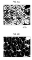
- Figs. 4A and 4B are polarizing microscope images of a surface of a piezoelectric ceramic of Example 2.
- Figs. 5A and 5B are polarizing microscope images of a surface of a piezoelectric ceramic of Example 6.
- a piezoelectric ceramic according to an embodiment of the present invention contains barium titanate and 0.04 mass% to 0.20 mass% manganese relative to barium titanate.
- the piezoelectric ceramic is constituted by crystal grains.
- the crystal grains contain crystal grains A having an equivalent circular diameter of 30 ⁇ m or more and 300 ⁇ m or less and crystal grains B having an equivalent circular diameter of 0.5 ⁇ m or more and 3 ⁇ m or less.
- the crystal grains A and the crystal grains B individually form aggregates.
- the aggregates of the crystal grains A and the aggregates of the crystal grains B form a sea-island structure.
- a “ceramic” means an aggregated body (also referred to as “bulk”) of crystal grains sintered by heat treatment, i.e., a polycrystal, and includes those subjected to processing after sintering. However, powder and slurry containing dispersed powder are excluded from the meaning.
- the main component of the piezoelectric ceramic is barium titanate.
- Barium titanate may be ABO 3 perovskite crystals such as those represented by general formula BaTiO 3 .
- main component is that the component primarily responsible for exhibiting the piezoelectric characteristics is barium titanate.
- piezoelectric ceramic may contain a component, such as manganese, for adjusting characteristics and production-induced unavoidable impurities.
- the barium titanate content in the piezoelectric ceramic is 95 mass% or more, preferably 97 mass% or more, and more preferably 99 mass% or more and 99.96 mass% or less.
- the components contained in the piezoelectric ceramic other than barium titanate may be contained in an amount of less than 5 mass%. When the components that do not contribute to the piezoelectric characteristics are contained in an amount exceeding 5 mass%, the piezoelectricity of the piezoelectric ceramic as a whole may become insufficient.
- the barium (Ba) sites of barium titanate may be partly substituted with another divalent metal or a pseudo-divalent metal.
- the divalent metal that substitutes the Ba sites include calcium (Ca) and strontium (Sr).
- the pseudo-divalent metal that substitutes the Ba sites include (Bi 0 . 5 Na 0 . 5 ) , (Bi 0 . 5 K 0 . 5 ), (Bi 0 . 5 Li 0 . 5 ) , (La 0 . 5 Na 0 . 5 ), (La 0 . 5 k 0 . 5 ), and (La 0 . 5 Li 0 . 5 ) .
- the substitution rate of partially substituting the Ba sites with another divalent metal or a pseudo-divalent metal is 20 atm% or less and preferably 10 atm% or less. When the substitution rate exceeds 20 atm%, high piezoelectric characteristics unique to barium titanate may not be satisfactorily obtained.
- Titanium (Ti) sites of barium titanate may be partly substituted with another tetravalent metal or a pseudo-tetravalent metal.
- the tetravalent metal that substitutes the Ti sites include zirconium (Zr), hafnium (Hf), silicon (Si), tin (Sn), and germanium (Ge).
- the pseudo-tetravalent metal that substitutes the Ti sites include combinations of divalent metals and pentavalent metals (M 2+ 1/3 M 5+ 2/3) , combinations of trivalent metals and pentavalent metals (M 3+ 1/2 M 5+ 1/2) , and combinations of trivalent metals and hexavalent metals (M 3+ 2/3 M 6+ 1/3 ) .
- the piezoelectric ceramic contains 0.04 mass% or more and 0.20 mass% or less and preferably 0.05 mass% or more and 0.17 mass% or less manganese relative to the barium titanate component.
- Manganese is not limited to metallic manganese. Manganese may take any form as long as it is contained as the manganese component in the piezoelectric ceramic. For example, manganese may be solid-dissolved in barium titanate. Manganese contained in the piezoelectric ceramic may be in a metallic form, an ionic form, an oxide form, a metal salt form, a complex form, etc.
- a piezoelectric ceramic containing barium titanate as a main component contains a manganese component in an amount within the aforementioned range, the insulating property and the mechanical quality factor (Qm) are improved.
- the effect brought about by addition of manganese does not occur if the manganese content is less than 0.04 mass%.
- the manganese content exceeds 0.20 mass%, the piezoelectricity of the piezoelectric ceramic as a whole may become insufficient due to mixing-in of hexagonal barium titanate having low piezoelectricity.
- Crystal grains of the piezoelectric ceramic contain barium titanate and manganese.
- the crystal grains include crystal grains A having an equivalent circular diameter of 30 ⁇ m or more and 300 ⁇ m or less and crystal grains B having an equivalent circular diameter of 0.5 ⁇ m or more and 3 ⁇ m or less.
- the crystal grains A and the crystal grains B individually form aggregates.
- the aggregates of the crystal grains A and the aggregates of the crystal grains B form a sea-island structure.
- the crystal grains A having an equivalent circular diameter of 30 ⁇ m or more and 300 ⁇ m or less improve the piezoelectric performance of the piezoelectric ceramic.
- the crystal grains B having an equivalent circular diameter of 0.5 ⁇ m or more and 3 ⁇ m or less form aggregates and enter into gaps between the crystal grains A to increase the packing property, thereby increasing the mechanical strength of the piezoelectric ceramic.
- the contact area between the crystal grains decreases and the mechanical strength is thereby decreased.
- the decrease in mechanical strength tends to cause cracking and breaking of the ceramic when the ceramic is used in a piezoelectric element.
- the ceramic contains aggregates of crystal grains B only, the degree of piezoelectricity becomes insufficient.
- the mechanical strength also tends to be slightly insufficient.
- the "equivalent circular diameter” means the diameter of a circle with an area equal to that of a projection of the crystal grain onto a plane, i.e., the diameter generally known as a "projected area equivalent diameter” in microscopy.
- the crystal grains are classified into crystal grains A, crystal grains B, and crystal grains C on an equivalent circular diameter basis.
- the method for measuring the equivalent circular diameter is not particularly limited.
- the equivalent circular diameter can be measured by performing image-processing on a photographic image of a surface of a piezoelectric ceramic taken by a polarizing microscope or a scanning electron microscope.
- the magnification used in obtaining the equivalent circular diameter of the crystal grains A is, for example, about 5 to 50.
- the magnification used in obtaining the equivalent circular diameter of the crystal grains B is, for example, about 500 to 5000. Either an optical microscope or an electron microscope may be used depending on the magnification.
- the equivalent circular diameter may be determined from an image of a polished surface or a cross section instead of the surface of the ceramic.
- the "sea-island structure” refers to a state of phase separation in a solid.
- a substance regarded as “islands”
- a substance regarded as “islands”
- a substance regarded as “sea”
- the “sea-island structure” refers to such a state.
- aggregates of crystal grains A and aggregates of crystal grains B serve as a sea and islands or vice versa.
- the crystal grains A and crystal grains B may contain barium titanate having the same non-centrosymmetric crystal structure to enhance the piezoelectric performance of the piezoelectric ceramic. Otherwise, the piezoelectric performance significantly degrade. Crystal grains that have a centrosymmetric crystal structure do not exhibit piezoelectricity.
- non-centrosymmetric crystal structure examples include tetragonal, rhombohedral, monoclinic, and orthorhombic systems.
- An example of the centrosymmetric crystal structure is a cubic system.
- the tetragonal system is most preferred.
- the piezoelectric performance of the piezoelectric ceramic are improved.
- the c/a ratio i.e., a parameter indicating the tetragonality of crystals, also displays similar values.
- the c/a ratio suitable for the piezoelectric ceramic having a tetragonal crystal structure is 1.005 or more and 1.025 or less.
- the aggregates of the crystal grains B may form the island portions of the sea-island structure.
- crystal grains A having high piezoelectricity and rigidity serve as the sea so as to constitute the aggregates of the piezoelectric ceramic
- aggregates of crystal grains B having high shape flexibility serve as the islands, the piezoelectric performance and the mechanical strength of the piezoelectric ceramic as a whole are improved.
- the piezoelectric ceramic may contain crystal grains C that do not satisfy the conditions set for the equivalent circular diameters of the crystal grains A and B.
- Examples of such grains include crystal grains having an equivalent circular diameter exceeding 300 ⁇ m, fine crystal grains having an equivalent circular diameter less than 0.5 ⁇ m, and small crystal grains having an equivalent circular diameter of more than 3 ⁇ m and less than 30 ⁇ m.
- Such crystal grains are referred to as "crystal grains C".
- the percentage of area occupied by the crystal grains C determined by observation of a surface or cross-section of the piezoelectric ceramic is preferably 10 area% or less and more preferably 5 area% or less. If more than 10 area% of crystal grains C exist, the piezoelectricity-improving effect brought about by the crystal grains A and the mechanical property-improving effect brought about by the crystal grains B may be degraded.
- the percentage of the area occupied by the crystal grains A determined by observation of a surface or cross-section of the piezoelectric ceramic is preferably 40 area% or more and 86 area% or less and more preferably 51 area% or more and 85 area% or less, and yet more preferably 73 area% or more and 85 area% or less.
- the piezoelectric performance of the piezoelectric ceramic are improved.
- the percentage of the crystal grains A is less than 40 area%, a high piezoelectric constant is not expected.
- the percentage of the crystal grains A is more than 86 area%, excessively large gaps are generated which may not be filled with the crystal grains B. As a result, the mechanical characteristics of the piezoelectric ceramic are degraded. In particular, the piezoelectric ceramic shows a tendency to crack.
- the percentage of the area occupied by the aggregates of the crystal grains B determined by observation of a surface or cross-section of the piezoelectric ceramic is 14 area% or more and 60 area% or less and preferably 15 area% or more and 49 area% or less.
- the area occupied by the aggregates of the crystal grains B includes the crystal grains B and grain boundaries of the crystal grains B.
- the area occupied by the aggregates of the crystal grains B is determined by subtracting the areas of the crystal grains A, crystal grains C, and missing portions from the observed view.
- the percentage of area occupied by the aggregates of the crystal grains B is less than 14 area%, the mechanical strength of the piezoelectric ceramic may be deficient.
- the percentage exceeds 60 area% the piezoelectric ceramic is not expected to exhibit a high piezoelectric constant.
- the crystal grains A and B of the piezoelectric ceramic both contain barium titanate as a main component and preferably contain 0.04 mass% to 0.20 mass% and more preferably 0.05 mass% to 0.17 mass% manganese relative to barium titanate. Since the crystal grains contain manganese in this range, the mechanical quality factor (Qm) of the piezoelectric ceramic is further increased and deterioration caused by depolarization is suppressed.
- a method for making the piezoelectric ceramic includes a step of sintering a mixture of barium titanate particles 1 containing 0.05 mass% to 2.0 mass% (metal basis) manganese and barium titanate particles 2 containing less than 0.04 mass% (metal basis) manganese.
- barium titanate particles 1 are distinguished from each other by naming them “barium titanate particles 1" and "barium titanate particles 2".
- the barium titanate particles 1 are abbreviated as BT-1 particles and the barium titanate particles 2 are abbreviated as BT-2 particles.
- the BT-1 particles are barium titanate particles containing 0.05 mass% to 2.0 mass% manganese on a metal basis.
- the manganese content in the BT-2 particles is less than 0.04 mass% on a metal basis.
- the BT-2 particles may be free of manganese.
- Manganese may be combined with the BT-1 particles and BT-2 particles in any form.
- manganese may be solid-dissolved in barium titanate particles.
- Manganese may be caused to adhere to barium titanate particles by taking an elemental metal form, an ion form, an oxide form, a metal salt form, a complex form, etc.
- the BT-1 particles and BT-2 particles may contain barium titanate, a component for adjusting characteristics other than manganese, and production-derived impurities.
- the impurities include metal-derived components such as aluminum, calcium, niobium, iron, and lead, glass components, and hydrocarbon-based organic components.
- the impurity content is preferably 5 mass% or less and more preferably 1 mass% or less.
- the particle diameter of the BT-1 and BT-2 particles as primary particles is not particularly limited.
- the primary particle diameter is preferably 5 nm to 300 nm and more preferably 50 nm to 150 nm to obtain a high-density homogeneous piezoelectric ceramic.
- the density of the ceramic after sintering may become deficient if the primary particle diameter is excessively large or small.
- "primary particles” mean individual particles of the minimum unit that can be clearly separated from the rest of the particles constituting the powder.
- the primary particles may be agglomerated to form larger secondary particles. Secondary particles may be intentionally produced by performing an agglomeration step using a polymeric binder.
- the method for making the BT-1 and BT-2 particles is not particularly limited.
- a manganese component may be added to commercially available or synthetic barium titanate particles during a post process.
- the method for adding the manganese component is not particularly limited but the manganese component are preferably uniformly adhered on the surface of barium titanate particles. From this viewpoint, a spray drying method is the most preferable method for adding the manganese component.
- a barium titanate precursor already containing a manganese component may be crystallized to form the BT-1 and BT-2 particles.
- an equimolar mixture of a barium compound and a titanium compound may be mixed with a desired amount of a manganese component and the resulting mixture may be calcined at about 1000°C to obtain manganese-dissolved barium titanate particles.
- Examples of the barium compound that can be used in making the BT-1 and BT-2 particles include barium carbonate, barium oxalate, barium oxide, barium aluminate, and various barium alkoxides.
- Examples of the titanium compound that can be used in making the BT-1 and BT-2 particles include titanium oxide.
- Examples of the manganese component that can be used in making the BT-1 and BT-2 particles include manganese compounds such as manganese oxide, manganese dioxide, and manganese acetate.
- the BT-1 particles differ from the BT-2 particles in the manganese content.
- barium titanate contains manganese, the rate of generating crystal growth nuclei during sintering is lowered. This tendency is more apparent when manganese is adhered on the particle surfaces than when manganese is dissolved in the particles.
- the sintered ceramic will include crystal grains with large diameters derived from the portions where the nuclei had been sparse and crystal grains with small diameters derived from the portions where the nuclei had been dense. Crystal grains with large diameters contribute to improving the piezoelectricity of the ceramic. The crystal grains with small diameters contribute to enhancing the mechanical strength of the ceramic since the contact area between the crystal grains is increased.
- the ratio of the BT-1 particles is 2 mass% or more and 90 mass% or less and preferably 5 mass% or more and 90 mass% or less.
- the ratio of the BT-1 particles is less than 2 mass%, the piezoelectric performance of the sintered ceramic may be degraded.
- the ratio of the BT-1 particles exceeds 90 mass%, the mechanical characteristics of the sintered ceramic may be lowered.
- the ratio of the BT-2 particles is 10 mass% or more and 98 mass% or less and preferably 10 mass% or more and 95 mass% or less.
- the method for mixing the particles is not particularly limited.
- the particles may be mixed in a solid state using a mortar or in a liquid phase dispersed state using a ball mill or a bead mill.
- the resulting barium titanate particle mixture is molded into a desired shape and sintered into a ceramic.
- the method for sintering-the ceramic is not particularly limited. Examples of the sintering method include a sintering method using an electric furnace, an electric heating method, a microwave sintering method, a millimeter-wave sintering method, and a hot isostatic pressing (HIP) method.
- the sintering temperature of the ceramic is not particularly limited and may be a temperature at which crystals of barium titanate grow sufficiently.
- the sintering temperature is preferably 1000°C or more and 1450°C or less and more preferably 1300°C or more and 1400°C or less.
- the barium titanate ceramic sintered in this temperature range shows good piezoelectric characteristics.
- sintering may be performed for about 1 hour more and 12 hours or less by retaining the sintering temperature constant in the above-described temperature range.
- a piezoelectric element that uses the piezoelectric ceramic will now be described.
- a piezoelectric element includes a first electrode, a piezoelectric ceramic, which is the piezoelectric ceramic described above, and a second electrode.
- the first electrode and the second electrode are each formed of a conductive layer having a thickness of about 5 nm to 2000 nm.
- the material for the electrodes is not particularly limited and any material generally used in piezoelectric elements may be used. Examples of the material include metals such as Ti, Pt, Ta, Ir, Sr, In, Sn, Au, Al, Fe, Cr, Ni, Pd, Cu, and Ag and oxides thereof.
- the first electrode and the second electrode may be composed of one of these materials or may be a laminate of two or more of these materials.
- the first electrode may be composed of a material different from that of the second electrode.
- the method for making the first electrode and the second electrode is not particularly limited.
- the electrodes may be formed by baking a metal paste, sputtering, or vapor deposition.
- the first electrode and the second electrode may be patterned into desired shapes.
- Figs. 1A and 1B are schematic views showing one embodiment of a liquid discharge head.
- the piezoelectric element includes a first electrode 6, a piezoelectric ceramic 7, and a second electrode 8.
- the liquid discharge head includes the piezoelectric element described above.
- Fig. 1A is a schematic view of the liquid discharge head.
- the liquid discharge head includes a discharge port 11, a connecting hole 12 that connects an individual liquid reservoir 13 to the discharge port 11, a common liquid reservoir 14, a diaphragm 15, and a piezoelectric element 10.
- the piezoelectric element 10 has a rectangular shape as shown in the drawing but may have an elliptic shape, a circular shape, a parallelogram shape, or the like.
- the piezoelectric ceramic 7 is formed into a shape that reflects the shape of the individual liquid reservoir.
- Fig. 1B is a cross-sectional view of the piezoelectric element taken in the width direction of the liquid discharge head shown in Fig. 1A .
- the cross-sectional shape of the piezoelectric element 10 is rectangular in the drawing, the shape may be trapezoidal or inverted trapezoidal.
- the first electrode 6 corresponds to a lower electrode 16 and the second electrode 8 corresponds to an upper electrode 18.
- the first electrode 6 may function as the lower electrode 16 or the upper electrode 18, and the second electrode 8 may also function as the lower electrode 16 or the upper electrode 18.
- a buffer layer 19 may be provided between the diaphragm 15 and the lower electrode 16.
- the diaphragm 15 moves vertically as the piezoelectric ceramic expands and contracts, thereby applying pressure to the liquid in the individual liquid reservoir and causing the liquid discharge head to discharge the liquid through the discharge port.
- the liquid discharge head can be used in printers and for making electronic devices.
- the thickness of the diaphragm 15 is 1.0 ⁇ m or more and 15 ⁇ m or less and preferably 1.5 ⁇ m or more and 8 ⁇ m or less.
- the material for the diaphragm 15 is not particularly limited but may be silicon.
- the buffer layer and the electrode layer on silicon may constitute part of the diaphragm 15.
- Silicon in the diaphragm 15 may be doped with boron (B) or phosphorus (P).
- the thickness of the buffer layer 19 is 300 nm or less and preferably 200 nm or less.
- the size of the discharge port 11 is preferably 5 ⁇ m or more and 40 ⁇ m or less in diameter.
- the discharge port 11 has a circular shape in the drawing but may have a star shape, a rectangular shape, or a triangular shape.
- FIGs. 2A and 2B are schematic views showing embodiments of ultrasonic motors.
- Fig. 2A shows an ultrasonic motor including a single plate-type piezoelectric element.
- the ultrasonic motor includes a transducer 24 prepared by bonding a piezoelectric element 22 onto a metal elastic ring 21 with an organic adhesive 23 (epoxy adhesive, cyanoacrylate adhesive, or the like), a rotor 25 is pressed against a sliding surface of the transducer 24 by a pressure spring (not shown in the drawing), and an output shaft that is integral with the rotor 25.
- an organic adhesive 23 epoxy adhesive, cyanoacrylate adhesive, or the like
- Fig. 2B shows an ultrasonic motor including a multilayered piezoelectric element.
- the ultrasonic motor includes a transducer 61 composed of a metal material.
- a plurality of piezoelectric elements 63 are interposed between cylindrical metal blocks and the metal blocks are fastened with bolts to hold the piezoelectric elements 63 therebetween, thereby constituting the transducer 61.
- the transducer 61 excites two types of vibrations orthogonally intersecting each other when AC voltages having different phases are applied to the driving piezoelectric ceramic of the piezoelectric element. When two vibrations are combined, the tip of the transducer 61 produces a circular vibration used for driving.
- a circumferential groove is formed in the upper part of the transducer 61 to increase the displacement of the vibration for driving.
- the ultrasonic rotor further includes a rotor 62 pressed against the transducer 61 by a pressure spring so that frictional force for driving is obtained.
- the piezoelectric element according to embodiments of the present invention is suitable for use in a liquid discharge head and an ultrasonic motor.
- a lead-free piezoelectric element mainly composed of barium titanate is included in a liquid discharge head, a head having a nozzle density and discharge power comparable or superior to those of heads using lead-based piezoelectric elements can be obtained.
- a lead-free piezoelectric element mainly composed of barium titanate is included in an ultrasonic motor, a motor having driving force and durability comparable or superior to those of motors using lead-based piezoelectric elements can be obtained.
- the piezoelectric ceramic according to embodiments of the present invention can be used not only in a liquid discharge head and a motor, but also in devices such as an ultrasonic vibrator, a piezoelectric actuator, and a piezoelectric sensor.
- Production Example 1 Production of manganese-containing barium titanate particles (raw material powder 1A)
- Manganese(II) acetate was allowed to adhere on surfaces of barium titanate particles having an average particle diameter of 100 nm (trade name BT-01, product of Sakai Chemical Industry Co., Ltd.) by using a spray drier.
- the manganese content in the resulting powder was 0.80 mass% according to inductively coupled plasma mass spectrometry (ICP-MS).
- the manganese content was adjustable by controlling the ratio of the raw material fed to the spray drier.
- the resulting powder corresponds to the barium titanate particles 1 described above and is referred to as "raw material powder 1A" hereinafter.
- Production Example 2 Production of manganese-containing barium titanate particles (raw material powder 2B)
- Barium titanate particles having a manganese content of 0.03 mass% were produced as in Production Example 1 except that the feed ratio of manganese(II) acetate was changed.
- the resulting powder corresponds to the barium titanate particles 2 described above and is referred to as "raw material powder 2B" hereinafter.
- Production Example 3 Production of manganese-containing barium titanate particles (raw material powder 1C)
- Barium titanate particles having a manganese content of 0.18 mass% were produced as in Production Example 1 except that the raw material for manganese was changed to manganese(II) oxide and its feed ratio was adjusted.
- the resulting powder corresponds to the barium titanate particles 1 described above and is referred to as "raw material powder 1C" hereinafter.
- Production Example 4 Production of manganese-free barium titanate particles (raw material powder 2D)
- Barium titanate particles having an average particle diameter of 100 nm (trade name BT-01, product of Sakai Chemical Industry Co., Ltd.) were dried in an electric furnace at 250°C for 3 hours.
- the resulting powder corresponds to the barium titanate particles 2 described above and is referred to as "raw material powder 2D" hereinafter.
- Production Example 5 Production of barium titanate particles containing manganese and calcium (raw material powder 1E)
- Barium titanate particles having an average particle diameter of 100 nm (trade name BT-01, product of Sakai Chemical Industry Co., Ltd.) and calcium titanate having an average particle diameter of 300 nm (trade name CT-03, product of Sakai Chemical Industry Co., Ltd.) were mixed with each other at a BT-01/CT-03 ratio of 9:1 on a molar basis in a ball mill for 24 hours.
- manganese(II) oxide was caused to adhere on particle surfaces of the mixed powder to obtain barium calcium titanate particles having a manganese content of 0.18 mass%.
- This powder corresponds to the barium titanate particles 1 described above and is referred to as "raw material powder 1E" hereinafter.
- Production Example 6 Production of barium titanate particles containing calcium but not manganese (raw material powder 2F)
- Barium titanate particles having an average particle diameter of 100 nm (trade name BT-01, product of Sakai Chemical Industry Co., Ltd.) and calcium titanate having an average particle diameter of 300 nm (trade name CT-03, product of Sakai Chemical Industry Co., Ltd.) were mixed with each other at a BT-01/CT-03 ratio of 9:1 on a molar basis in a ball mill for 24 hours.
- the resulting mixed powder was dried in an electric furnace at 250°C for 3 hours.
- the resulting powder corresponds to the barium titanate particles 2 described above and is referred to as "raw material powder 2F" hereinafter.
- Table 1 shows production conditions of piezoelectric ceramics of Examples 1 to 7.
- Table 1 Type of Particles 1 Type of Particles 2 Mass ratio (Particles 1/Particles 2) Sintering temperature (°C) Sintering time (Hr) Example 1 1C 2B 65/35 1360 5 Example 2 1C 2D 90/10 1340 5 Example 3 1C 2B 10/90 1380 5 Example 4 1C 2D 50/50 1280 5 Example 5 1A 2B 30/70 1420 5 Example 6 1A 2D 5/95 1300 5 Example 7 1E 2F 80/20 1450 8 Comparative Example 1 1C None 100/0 1400 5 Comparative Example 2 1C None 100/0 1300 5 Comparative Example 3 1C None 100/0 1150 5 Comparative Example 4 None 2D 0/100 1150 15
- Table 2 shows analytic data regarding the composition, structure, and characteristics of the piezoelectric ceramic obtained thereby.
- Each sintered body obtained as above was polished into a disk-shaped piece having a thickness of 1 mm to conduct X-ray diffractometry (XRD), X-ray fluorescence analysis (XRF), and Archimedean density measurement.
- XRD X-ray diffractometry
- XRF X-ray fluorescence analysis
- Archimedean density measurement Although not indicated in Table 2, all piezoelectric ceramics were composed of a perovskite single phase mainly composed of barium titanate. All piezoelectric ceramics exhibited a high density of 95% or more with respect to the theoretical density of barium titanate.
- the piezoelectric ceramic of Example 7 exhibited a high density of 95% or more with respect to the theoretical density of (Ba 0 . 9 Ca 0 . 1 ) TiO 3 .
- the state of crystal grains of the piezoelectric ceramics was observed mainly with a polarizing microscope.
- a scanning electron microscope (SEM) was used in determining the diameter of small crystal grains. Observation was conducted on a surface of the ceramic after sintering and a surface of the ceramic after polishing. The size and conditions of the crystal grains were not significantly different between the two surfaces. Thus, while Table 2 indicates data of the surface after sintering as representative examples, the same tendencies are observed in sections formed by polishing.
- Figs. 3A to 5B show examples of polarizing microscope images taken during the above-described microscopic observation.
- Fig. 3A is an enlarged photograph of a surface of a piezoelectric ceramic of Example 1 taken with the polarizing microscope and
- Fig. 3B is an image obtained by performing image-processing on the photograph shown in Fig. 3A .
- Fig. 4A is an enlarged photograph of a surface of a piezoelectric ceramic of Example 2 taken with the polarizing microscope and Fig. 4B is an image obtained by performing image-processing on the photograph shown in Fig. 4A .
- Fig. 5A is an enlarged photograph of a surface of a piezoelectric ceramic of Example 6 taken with the polarizing microscope and Fig. 5B is an image obtained by performing image-processing on the photograph shown in Fig. 5A .
- All piezoelectric ceramics of Examples had crystal grains A and crystal grains B, and aggregates of the crystal grains A and B formed a sea-island structure.
- large crystal grains indicated by a light color substantially have an equivalent circular diameter of 30 ⁇ m or more and 300 ⁇ m or less and thus satisfy the conditions of the crystal grains A.
- These crystal grains A are aggregated with each other and form single continuous structure at least in the region shown in the photograph. This is the state of "sea".
- Fig. 3A also shows dark regions that lie in gaps in the "sea”. These regions were enlarged and observed. The regions were composed of relatively small crystal grains that had an equivalent circular diameter of about 0.5 ⁇ m to 3 ⁇ m and thus satisfied the conditions of crystal grains B. The crystal grains B are aggregated with each other and found in dispersed positions so as fill the spaces between the aggregates of the crystal grains A. This is the state of "island".
- the image shown in Fig. 3B was obtained by binalizing the microscope photograph shown in Fig. 3A by image processing.
- the portions that satisfy conditions of the crystal grains A are indicated in black and other portions are indicated in white.
- Other photographs were processed in the same manner and analyzed to determine the percentage of the area occupied by the crystal grains A.
- the results are indicated in Table 2.
- the percentage of the area occupied by the crystal grains C was also calculated by changing the threshold of the image processing.
- the percentage of the remaining area other than those occupied by the crystal grains A and C is the percentage of the area occupied by the aggregates of the crystal grains B, i.e., the crystal grains B and crystal boundaries.
- the crystal structures of the crystal grains A and B were determined with X-ray micro beam diffractometer (product of Bruker AXS) for evaluating thin film materials.
- the beam diameter was 100 ⁇ m and 2 ⁇ / ⁇ measurement was conducted by irradiating either an aggregate of the crystal grains A or an aggregate of the crystal grains B with this beam.
- the crystal grains A had tetragonal structures with c/a of about 1.02.
- the crystal structure of the crystal grains B is as indicated in Table 2.
- the manganese contents in the crystal grains A and crystal grains B were determined by electron energy loss spectroscopy (EELS) with a transmission electron microscope (TEM). The results are indicated in Table 2.
- the manganese content in the entire piezoelectric ceramic was determined with an X-ray fluorescent analyzer (product of PANalytical) by wavelength dispersive XRF.
- the manganese contents relative to the barium titanate component determined as such were as follows:
- Table 1 shows production conditions for piezoelectric ceramics of Comparative Examples 1 to 4. Comparative piezoelectric ceramics were produced as in Example 1 except for the conditions described in Table 1.
- sintering of the piezoelectric ceramic was carried out by a resistance heating/two-step sintering technique involving causing the sintering temperature to overshoot to a temperature at least 40°C higher than the sintering temperature.
- a temperature of 1320°C was retained for 1 minute and then a temperature of 1150°C was retained for 15 hours.
- Table 2 shows analytic data regarding the composition, structure, and characteristics of the piezoelectric ceramics of Comparative Examples.
- the analytical procedures were the same as in Example 1.
- the manganese contents in the piezoelectric ceramics of Comparative Examples relative to the barium titanate component were as follows:
- All piezoelectric ceramics of Comparative Examples were composed of crystals of a perovskite single phase mainly composed of barium titanate. Although the density of the piezoelectric ceramics of Comparative Examples 2 and 4 was satisfactory, i.e., 95% or more, the density of the piezoelectric ceramic of Comparative Example 1 was about 90% and the density of the piezoelectric ceramic of Comparative Example 3 was about 92%.
- the size and state of the crystal grains of the piezoelectric ceramics were observed as in Example 1.
- the size of the crystal grains was uniform in all piezoelectric ceramics. In other words, since only one type of crystal grains were generally present, the sea-island structure was not formed by the crystal grains in the ceramics.
- the crystal grains of Comparative Examples 1, 2, and 4 had a tetragonal crystal structure with c/a of about 1.02.
- the crystal grains of Comparative Example 3 had a cubic crystal structure with c/a substantially equal to 1.
- Gold electrodes were formed on the front and rear sides of the disk-shaped ceramic described above by DC sputtering.
- the ceramic with the electrodes was cut into a rectangular solid-shaped ceramic 12 mm x 3 mm x 1 mm in size.
- the rectangular solid-shaped ceramic was polarized in silicone oil.
- the oil temperature was 100°C
- the polarization voltage was DC 1 kV
- the voltage application time was 15 minutes.
- the piezoelectric constant was measured using the polarized rectangular solid-shaped ceramic.
- the dependency of the impedance of the ceramic sample on the frequency was measured with an impedance analyzer (trade name 4294A, product of Agilent).
- the piezoelectric constant d 31 (pm/V) was determined from the observed resonance frequency and antiresonance frequency.
- the piezoelectric constant d 31 is a negative number.
- the piezoelectric performance is high when the absolute value of the piezoelectric constant d 31 is large. The results are shown in Table 2.
- the mechanical strength was evaluated by a three-point bending test with a tension-compression tester (trade name TENSILON RTC-1250A, product of ORIENTEC Co. Ltd.).
- a rectangular solid-shaped ceramic 12 mm x 3 mm x 1 mm in size was used in the evaluation. No electrodes were formed and thus no polarization was performed.
- Table 2 shows the maximum stress observed when the stress applied to the rectangular solid-shaped ceramic sample is increased until the sample is broken.
- a sufficient mechanical strength for continuously driving a piezoelectric element is a maximum stress of 40 MPa or more.
- Example 1 had the best characteristics.
- a liquid discharge head and ultrasonic motors shown in Figs. 1A, 1B , 2A, and 2B were made by using the piezoelectric ceramic of Example 1. It was confirmed that the liquid discharge head discharged ink according to input electrical signals and that the ultrasonic motors turned according to application of the alternating voltage.
- the piezoelectric ceramic according to embodiments of the present invention has good piezoelectric characteristics and mechanical strength and low impact on environment.
- the piezoelectric ceramic can be used in devices that widely use piezoelectric ceramics, such as liquid discharge heads, ultrasonic motors, and piezoelectric elements.
Abstract
Description
- The present invention relates generally to piezoelectric ceramics, methods for making the piezoelectric ceramics, piezoelectric elements, liquid discharge heads, and ultrasonic motors. In particular it relates to a barium titanate piezoelectric ceramic that has controlled crystal grain size and thereby exhibits good piezoelectric performance and mechanical strength, a method for making the piezoelectric ceramic, a piezoelectric element that uses the piezoelectric ceramic, and a liquid discharge head and an ultrasonic motor that use the liquid discharge element.
- ABO3 perovskite oxides such as lead zirconate titanate (hereinafter referred to as "PZT") are generally used as piezoelectric ceramics.
- However, since PZT contains lead as the A-site element, PZT may have an adverse effect on the surrounding environment. Accordingly, piezoelectric ceramics that use lead-free perovskite oxides are sought after.
- Barium titanate is known as a lead-free perovskite piezoelectric ceramic material. Japanese Patent Laid-Open No.
2008-150247 - However, according to the two-step sintering technique, the retention time of the first sintering temperature needs to be short. As a result, the temperature of the ceramic to be sintered becomes inhomogeneous and the piezoelectric characteristics are not always satisfactorily reproduced. For example, the temperature of a barium titanate ceramic piece of a practical size does not become homogeneous if the retention time is about 1 minute. In other words, an ideal nanostructure is not realized in all parts of the sintered ceramics. Thus, there have been no barium titanate ceramics that achieve piezoelectric characteristics sufficient to replace PZT.
- The piezoelectric performance of barium titanate may be improved by increasing the crystal grain diameter. Japanese Patent No.
4039029 - In Japanese Patent No.
4039029 - However, when the average grain diameter of the barium titanate ceramic is increased by the aforementioned techniques, the contact area between the crystal grains is decreased. Thus, the mechanical strength of the ceramic drops and ceramic parts become fragile during processing and driving of the piezoelectric element. In sum, it is desirable that barium titanate piezoelectric ceramics achieve both good piezoelectric characteristics and high mechanical strength.
- It is desirable to provide a piezoelectric ceramic having good piezoelectric characteristics and mechanical strength, a method for making such a piezoelectric ceramic, a piezoelectric element including the piezoelectric ceramic, and a liquid discharge head and an ultrasonic motor including the piezoelectric element.
- The present invention in its first aspect provides a piezoelectric ceramic as specified in claims 1 to 8.
- The present invention in its second aspect provides a piezoelectric element as specified in Claim 9.
- The present invention in its third aspect provides a liquid discharge head as specified in
Claim 10. - The present invention in its fourth aspect provides an ultrasonic motor as specified in
Claim 11. - The present invention in its fifth aspect provides a method for making a piezoelectric ceramic as specified in
Claims - Further features of the present invention will become apparent from the following description of exemplary embodiments (with reference to the attached drawings).
-
Figs. 1A and 1B are schematic views showing one embodiment of a liquid discharge head. -
Figs. 2A and 2B are schematic views showing embodiments of ultrasonic motors. -
Figs. 3A and 3B are polarizing microscope images of a surface of a piezoelectric ceramic of Example 1. -
Figs. 4A and 4B are polarizing microscope images of a surface of a piezoelectric ceramic of Example 2. -
Figs. 5A and 5B are polarizing microscope images of a surface of a piezoelectric ceramic of Example 6. - The embodiments of the present invention will now be described.
- A piezoelectric ceramic according to an embodiment of the present invention contains barium titanate and 0.04 mass% to 0.20 mass% manganese relative to barium titanate. The piezoelectric ceramic is constituted by crystal grains. The crystal grains contain crystal grains A having an equivalent circular diameter of 30 µm or more and 300 µm or less and crystal grains B having an equivalent circular diameter of 0.5 µm or more and 3 µm or less. The crystal grains A and the crystal grains B individually form aggregates. The aggregates of the crystal grains A and the aggregates of the crystal grains B form a sea-island structure.
- In the present invention, a "ceramic" means an aggregated body (also referred to as "bulk") of crystal grains sintered by heat treatment, i.e., a polycrystal, and includes those subjected to processing after sintering. However, powder and slurry containing dispersed powder are excluded from the meaning.
- The main component of the piezoelectric ceramic is barium titanate. Barium titanate may be ABO3 perovskite crystals such as those represented by general formula BaTiO3 .
- The meaning of the "main component" is that the component primarily responsible for exhibiting the piezoelectric characteristics is barium titanate. For example, piezoelectric ceramic may contain a component, such as manganese, for adjusting characteristics and production-induced unavoidable impurities.
- In particular, the barium titanate content in the piezoelectric ceramic is 95 mass% or more, preferably 97 mass% or more, and more preferably 99 mass% or more and 99.96 mass% or less. The components contained in the piezoelectric ceramic other than barium titanate may be contained in an amount of less than 5 mass%. When the components that do not contribute to the piezoelectric characteristics are contained in an amount exceeding 5 mass%, the piezoelectricity of the piezoelectric ceramic as a whole may become insufficient.
- The barium (Ba) sites of barium titanate may be partly substituted with another divalent metal or a pseudo-divalent metal. Examples of the divalent metal that substitutes the Ba sites include calcium (Ca) and strontium (Sr). Examples of the pseudo-divalent metal that substitutes the Ba sites include (Bi0.5Na0.5) , (Bi0.5K0.5), (Bi0.5Li0.5) , (La0.5Na0.5), (La0.5k0.5), and (La0.5Li0.5) . The substitution rate of partially substituting the Ba sites with another divalent metal or a pseudo-divalent metal is 20 atm% or less and preferably 10 atm% or less. When the substitution rate exceeds 20 atm%, high piezoelectric characteristics unique to barium titanate may not be satisfactorily obtained.
- Titanium (Ti) sites of barium titanate may be partly substituted with another tetravalent metal or a pseudo-tetravalent metal. Examples of the tetravalent metal that substitutes the Ti sites include zirconium (Zr), hafnium (Hf), silicon (Si), tin (Sn), and germanium (Ge). Examples of the pseudo-tetravalent metal that substitutes the Ti sites include combinations of divalent metals and pentavalent metals (M2+ 1/3M5+ 2/3), combinations of trivalent metals and pentavalent metals (M3+ 1/2M5+ 1/2), and combinations of trivalent metals and hexavalent metals (M3+ 2/3M6+ 1/3) .
- The piezoelectric ceramic contains 0.04 mass% or more and 0.20 mass% or less and preferably 0.05 mass% or more and 0.17 mass% or less manganese relative to the barium titanate component. Manganese is not limited to metallic manganese. Manganese may take any form as long as it is contained as the manganese component in the piezoelectric ceramic. For example, manganese may be solid-dissolved in barium titanate. Manganese contained in the piezoelectric ceramic may be in a metallic form, an ionic form, an oxide form, a metal salt form, a complex form, etc. When a piezoelectric ceramic containing barium titanate as a main component contains a manganese component in an amount within the aforementioned range, the insulating property and the mechanical quality factor (Qm) are improved. The effect brought about by addition of manganese does not occur if the manganese content is less than 0.04 mass%. When the manganese content exceeds 0.20 mass%, the piezoelectricity of the piezoelectric ceramic as a whole may become insufficient due to mixing-in of hexagonal barium titanate having low piezoelectricity.
- Crystal grains of the piezoelectric ceramic contain barium titanate and manganese. The crystal grains include crystal grains A having an equivalent circular diameter of 30 µm or more and 300 µm or less and crystal grains B having an equivalent circular diameter of 0.5 µm or more and 3 µm or less. The crystal grains A and the crystal grains B individually form aggregates. The aggregates of the crystal grains A and the aggregates of the crystal grains B form a sea-island structure.
- The crystal grains A having an equivalent circular diameter of 30 µm or more and 300 µm or less improve the piezoelectric performance of the piezoelectric ceramic. The crystal grains B having an equivalent circular diameter of 0.5 µm or more and 3 µm or less form aggregates and enter into gaps between the crystal grains A to increase the packing property, thereby increasing the mechanical strength of the piezoelectric ceramic.
- If the ceramic contains aggregates of crystal grains A only, the contact area between the crystal grains decreases and the mechanical strength is thereby decreased. The decrease in mechanical strength tends to cause cracking and breaking of the ceramic when the ceramic is used in a piezoelectric element. In contrast, if the ceramic contains aggregates of crystal grains B only, the degree of piezoelectricity becomes insufficient. Moreover, since there is no structure that serves as a core, the mechanical strength also tends to be slightly insufficient.
- In this invention, the "equivalent circular diameter" means the diameter of a circle with an area equal to that of a projection of the crystal grain onto a plane, i.e., the diameter generally known as a "projected area equivalent diameter" in microscopy. The crystal grains are classified into crystal grains A, crystal grains B, and crystal grains C on an equivalent circular diameter basis. The method for measuring the equivalent circular diameter is not particularly limited. For example, the equivalent circular diameter can be measured by performing image-processing on a photographic image of a surface of a piezoelectric ceramic taken by a polarizing microscope or a scanning electron microscope. The magnification used in obtaining the equivalent circular diameter of the crystal grains A is, for example, about 5 to 50. The magnification used in obtaining the equivalent circular diameter of the crystal grains B is, for example, about 500 to 5000. Either an optical microscope or an electron microscope may be used depending on the magnification. The equivalent circular diameter may be determined from an image of a polished surface or a cross section instead of the surface of the ceramic.
- In this invention, the "sea-island structure" refers to a state of phase separation in a solid. In other words, when solid matter is roughly composed of two kinds of substances, a substance (regarded as "islands") may be mixed with and exist in a discontinuous manner within a substance (regarded as "sea") that appears to be relatively continuous. The "sea-island structure" refers to such a state. In particular, aggregates of crystal grains A and aggregates of crystal grains B serve as a sea and islands or vice versa. When the aggregates of crystal grains A and aggregates of crystal grains B are not separated from each other and remain mixed with each other, piezoelectricity and mechanical strength can be obtained for the piezoelectric ceramic.
- The crystal grains A and crystal grains B may contain barium titanate having the same non-centrosymmetric crystal structure to enhance the piezoelectric performance of the piezoelectric ceramic. Otherwise, the piezoelectric performance significantly degrade. Crystal grains that have a centrosymmetric crystal structure do not exhibit piezoelectricity.
- Examples of the non-centrosymmetric crystal structure include tetragonal, rhombohedral, monoclinic, and orthorhombic systems. An example of the centrosymmetric crystal structure is a cubic system. Of the non-centrosymmetric crystal structures described above, the tetragonal system is most preferred. When both the crystal grains A and crystal grains B have a tetragonal crystal structure, the piezoelectric performance of the piezoelectric ceramic are improved. When the composition and the crystal structure of the crystal grains A are substantially the same as those of the crystal grains B, the c/a ratio, i.e., a parameter indicating the tetragonality of crystals, also displays similar values. The c/a ratio suitable for the piezoelectric ceramic having a tetragonal crystal structure is 1.005 or more and 1.025 or less.
- The aggregates of the crystal grains B may form the island portions of the sea-island structure. When crystal grains A having high piezoelectricity and rigidity serve as the sea so as to constitute the aggregates of the piezoelectric ceramic, and aggregates of crystal grains B having high shape flexibility serve as the islands, the piezoelectric performance and the mechanical strength of the piezoelectric ceramic as a whole are improved.
- The piezoelectric ceramic may contain crystal grains C that do not satisfy the conditions set for the equivalent circular diameters of the crystal grains A and B. Examples of such grains include crystal grains having an equivalent circular diameter exceeding 300 µm, fine crystal grains having an equivalent circular diameter less than 0.5 µm, and small crystal grains having an equivalent circular diameter of more than 3 µm and less than 30 µm. Such crystal grains are referred to as "crystal grains C". The percentage of area occupied by the crystal grains C determined by observation of a surface or cross-section of the piezoelectric ceramic is preferably 10 area% or less and more preferably 5 area% or less. If more than 10 area% of crystal grains C exist, the piezoelectricity-improving effect brought about by the crystal grains A and the mechanical property-improving effect brought about by the crystal grains B may be degraded.
- The percentage of the area occupied by the crystal grains A determined by observation of a surface or cross-section of the piezoelectric ceramic is preferably 40 area% or more and 86 area% or less and more preferably 51 area% or more and 85 area% or less, and yet more preferably 73 area% or more and 85 area% or less. When the area occupied by the crystal grains A is within the above described range, the piezoelectric performance of the piezoelectric ceramic are improved. When the percentage of the crystal grains A is less than 40 area%, a high piezoelectric constant is not expected. In contrast, when the percentage of the crystal grains A is more than 86 area%, excessively large gaps are generated which may not be filled with the crystal grains B. As a result, the mechanical characteristics of the piezoelectric ceramic are degraded. In particular, the piezoelectric ceramic shows a tendency to crack.
- The percentage of the area occupied by the aggregates of the crystal grains B determined by observation of a surface or cross-section of the piezoelectric ceramic is 14 area% or more and 60 area% or less and preferably 15 area% or more and 49 area% or less. The area occupied by the aggregates of the crystal grains B includes the crystal grains B and grain boundaries of the crystal grains B. In particular, the area occupied by the aggregates of the crystal grains B is determined by subtracting the areas of the crystal grains A, crystal grains C, and missing portions from the observed view. When the percentage of area occupied by the aggregates of the crystal grains B is less than 14 area%, the mechanical strength of the piezoelectric ceramic may be deficient. When the percentage exceeds 60 area%, the piezoelectric ceramic is not expected to exhibit a high piezoelectric constant.
- The crystal grains A and B of the piezoelectric ceramic both contain barium titanate as a main component and preferably contain 0.04 mass% to 0.20 mass% and more preferably 0.05 mass% to 0.17 mass% manganese relative to barium titanate. Since the crystal grains contain manganese in this range, the mechanical quality factor (Qm) of the piezoelectric ceramic is further increased and deterioration caused by depolarization is suppressed.
- A method for making the piezoelectric ceramic will now be described.
- A method for making the piezoelectric ceramic includes a step of sintering a mixture of barium titanate particles 1 containing 0.05 mass% to 2.0 mass% (metal basis) manganese and barium titanate particles 2 containing less than 0.04 mass% (metal basis) manganese. Hereinafter, the two types of barium titanate particles are distinguished from each other by naming them "barium titanate particles 1" and "barium titanate particles 2". The barium titanate particles 1 are abbreviated as BT-1 particles and the barium titanate particles 2 are abbreviated as BT-2 particles.
- The BT-1 particles are barium titanate particles containing 0.05 mass% to 2.0 mass% manganese on a metal basis. The manganese content in the BT-2 particles is less than 0.04 mass% on a metal basis. The BT-2 particles may be free of manganese.
- Manganese may be combined with the BT-1 particles and BT-2 particles in any form. For example, manganese may be solid-dissolved in barium titanate particles. Manganese may be caused to adhere to barium titanate particles by taking an elemental metal form, an ion form, an oxide form, a metal salt form, a complex form, etc.
- The BT-1 particles and BT-2 particles may contain barium titanate, a component for adjusting characteristics other than manganese, and production-derived impurities. Examples of the impurities include metal-derived components such as aluminum, calcium, niobium, iron, and lead, glass components, and hydrocarbon-based organic components. The impurity content is preferably 5 mass% or less and more preferably 1 mass% or less.
- The particle diameter of the BT-1 and BT-2 particles as primary particles is not particularly limited. However, the primary particle diameter is preferably 5 nm to 300 nm and more preferably 50 nm to 150 nm to obtain a high-density homogeneous piezoelectric ceramic. The density of the ceramic after sintering may become deficient if the primary particle diameter is excessively large or small. Here, "primary particles" mean individual particles of the minimum unit that can be clearly separated from the rest of the particles constituting the powder. The primary particles may be agglomerated to form larger secondary particles. Secondary particles may be intentionally produced by performing an agglomeration step using a polymeric binder.
- The method for making the BT-1 and BT-2 particles is not particularly limited. In order to form manganeseclad barium titanate, a manganese component may be added to commercially available or synthetic barium titanate particles during a post process. The method for adding the manganese component is not particularly limited but the manganese component are preferably uniformly adhered on the surface of barium titanate particles. From this viewpoint, a spray drying method is the most preferable method for adding the manganese component.
- In order to form barium titanate in which manganese is dissolved, a barium titanate precursor already containing a manganese component may be crystallized to form the BT-1 and BT-2 particles. For example, an equimolar mixture of a barium compound and a titanium compound may be mixed with a desired amount of a manganese component and the resulting mixture may be calcined at about 1000°C to obtain manganese-dissolved barium titanate particles.
- Examples of the barium compound that can be used in making the BT-1 and BT-2 particles include barium carbonate, barium oxalate, barium oxide, barium aluminate, and various barium alkoxides.
- Examples of the titanium compound that can be used in making the BT-1 and BT-2 particles include titanium oxide. Examples of the manganese component that can be used in making the BT-1 and BT-2 particles include manganese compounds such as manganese oxide, manganese dioxide, and manganese acetate.
- The BT-1 particles differ from the BT-2 particles in the manganese content. When barium titanate contains manganese, the rate of generating crystal growth nuclei during sintering is lowered. This tendency is more apparent when manganese is adhered on the particle surfaces than when manganese is dissolved in the particles.
- When BT-1 particles and BT-2 particles are mixed and fired, portions in which crystal nuclei are dense and portions in which crystal growth nuclei are sparse are formed inside the ceramic undergoing sintering since the crystal nucleation rate differs between the BT-1 particles and BT-2 particles. Due to uneven distribution of the nuclei, the sintered ceramic will include crystal grains with large diameters derived from the portions where the nuclei had been sparse and crystal grains with small diameters derived from the portions where the nuclei had been dense. Crystal grains with large diameters contribute to improving the piezoelectricity of the ceramic. The crystal grains with small diameters contribute to enhancing the mechanical strength of the ceramic since the contact area between the crystal grains is increased.
- In the step of mixing the BT-1 particles and the BT-2 particles, the ratio of the BT-1 particles is 2 mass% or more and 90 mass% or less and preferably 5 mass% or more and 90 mass% or less. When the ratio of the BT-1 particles is less than 2 mass%, the piezoelectric performance of the sintered ceramic may be degraded. In contrast, when the ratio of the BT-1 particles exceeds 90 mass%, the mechanical characteristics of the sintered ceramic may be lowered.
- In the step of mixing the BT-1 particles and the BT-2 particles, the ratio of the BT-2 particles is 10 mass% or more and 98 mass% or less and preferably 10 mass% or more and 95 mass% or less. The method for mixing the particles is not particularly limited. The particles may be mixed in a solid state using a mortar or in a liquid phase dispersed state using a ball mill or a bead mill.
- The resulting barium titanate particle mixture is molded into a desired shape and sintered into a ceramic. The method for sintering-the ceramic is not particularly limited. Examples of the sintering method include a sintering method using an electric furnace, an electric heating method, a microwave sintering method, a millimeter-wave sintering method, and a hot isostatic pressing (HIP) method.
- The sintering temperature of the ceramic is not particularly limited and may be a temperature at which crystals of barium titanate grow sufficiently. The sintering temperature is preferably 1000°C or more and 1450°C or less and more preferably 1300°C or more and 1400°C or less. The barium titanate ceramic sintered in this temperature range shows good piezoelectric characteristics.
- In order to stabilize characteristics of the piezoelectric ceramic obtained by sintering with good reproducibility, sintering may be performed for about 1 hour more and 12 hours or less by retaining the sintering temperature constant in the above-described temperature range.
- A piezoelectric element that uses the piezoelectric ceramic will now be described.
- A piezoelectric element includes a first electrode, a piezoelectric ceramic, which is the piezoelectric ceramic described above, and a second electrode.
- The first electrode and the second electrode are each formed of a conductive layer having a thickness of about 5 nm to 2000 nm. The material for the electrodes is not particularly limited and any material generally used in piezoelectric elements may be used. Examples of the material include metals such as Ti, Pt, Ta, Ir, Sr, In, Sn, Au, Al, Fe, Cr, Ni, Pd, Cu, and Ag and oxides thereof. The first electrode and the second electrode may be composed of one of these materials or may be a laminate of two or more of these materials. The first electrode may be composed of a material different from that of the second electrode.
- The method for making the first electrode and the second electrode is not particularly limited. The electrodes may be formed by baking a metal paste, sputtering, or vapor deposition. The first electrode and the second electrode may be patterned into desired shapes.
-
Figs. 1A and 1B are schematic views showing one embodiment of a liquid discharge head. As shown inFig. 1B , the piezoelectric element includes a first electrode 6, apiezoelectric ceramic 7, and a second electrode 8. - The liquid discharge head includes the piezoelectric element described above.
Fig. 1A is a schematic view of the liquid discharge head. The liquid discharge head includes adischarge port 11, a connectinghole 12 that connects anindividual liquid reservoir 13 to thedischarge port 11, acommon liquid reservoir 14, adiaphragm 15, and apiezoelectric element 10. Thepiezoelectric element 10 has a rectangular shape as shown in the drawing but may have an elliptic shape, a circular shape, a parallelogram shape, or the like. In general, thepiezoelectric ceramic 7 is formed into a shape that reflects the shape of the individual liquid reservoir. - The
piezoelectric element 10 of the liquid discharge head and components near thepiezoelectric element 10 will now be described in detail with reference toFig. 1B. Fig. 1B is a cross-sectional view of the piezoelectric element taken in the width direction of the liquid discharge head shown inFig. 1A . Although the cross-sectional shape of thepiezoelectric element 10 is rectangular in the drawing, the shape may be trapezoidal or inverted trapezoidal. In the drawing, the first electrode 6 corresponds to alower electrode 16 and the second electrode 8 corresponds to anupper electrode 18. However, the first electrode 6 may function as thelower electrode 16 or theupper electrode 18, and the second electrode 8 may also function as thelower electrode 16 or theupper electrode 18. Abuffer layer 19 may be provided between thediaphragm 15 and thelower electrode 16. - The
diaphragm 15 moves vertically as the piezoelectric ceramic expands and contracts, thereby applying pressure to the liquid in the individual liquid reservoir and causing the liquid discharge head to discharge the liquid through the discharge port. The liquid discharge head can be used in printers and for making electronic devices. - The thickness of the
diaphragm 15 is 1.0 µm or more and 15 µm or less and preferably 1.5 µm or more and 8 µm or less. The material for thediaphragm 15 is not particularly limited but may be silicon. The buffer layer and the electrode layer on silicon may constitute part of thediaphragm 15. Silicon in thediaphragm 15 may be doped with boron (B) or phosphorus (P). - The thickness of the
buffer layer 19 is 300 nm or less and preferably 200 nm or less. The size of thedischarge port 11 is preferably 5 µm or more and 40 µm or less in diameter. Thedischarge port 11 has a circular shape in the drawing but may have a star shape, a rectangular shape, or a triangular shape. - An ultrasonic motor that uses the piezoelectric element will now be described.
Figs. 2A and 2B are schematic views showing embodiments of ultrasonic motors. -
Fig. 2A shows an ultrasonic motor including a single plate-type piezoelectric element. The ultrasonic motor includes atransducer 24 prepared by bonding apiezoelectric element 22 onto a metalelastic ring 21 with an organic adhesive 23 (epoxy adhesive, cyanoacrylate adhesive, or the like), arotor 25 is pressed against a sliding surface of thetransducer 24 by a pressure spring (not shown in the drawing), and an output shaft that is integral with therotor 25. - When an AC voltage is applied from a two-phase power source (phases differ by n/2) to the piezoelectric element, flexural progressive waves are generated in the
transducer 24 and individual points in the sliding surface of thetransducer 24 undergo elliptical motion. When therotor 25 is pressed against the sliding surface of thistransducer 24, therotor 25 receives frictional force from thetransducer 24 and rotates in the direction of the elliptical motion on the sliding surface of thetransducer 24. An object to be driven (not shown in the drawing) is joined to the output shaft by coupling or the like, and driven by the turning force of therotor 25. When a voltage is applied to a piezoelectric ceramic, the piezoelectric element expands and contracts due to a transversal piezoelectric effect and thus an elastic body, such as metal, joined to the piezoelectric element is bent. This principle is utilized by motors of the above-described type. -
Fig. 2B shows an ultrasonic motor including a multilayered piezoelectric element. The ultrasonic motor includes atransducer 61 composed of a metal material. A plurality ofpiezoelectric elements 63 are interposed between cylindrical metal blocks and the metal blocks are fastened with bolts to hold thepiezoelectric elements 63 therebetween, thereby constituting thetransducer 61. Thetransducer 61 excites two types of vibrations orthogonally intersecting each other when AC voltages having different phases are applied to the driving piezoelectric ceramic of the piezoelectric element. When two vibrations are combined, the tip of thetransducer 61 produces a circular vibration used for driving. A circumferential groove is formed in the upper part of thetransducer 61 to increase the displacement of the vibration for driving. - The ultrasonic rotor further includes a
rotor 62 pressed against thetransducer 61 by a pressure spring so that frictional force for driving is obtained. - As previously discussed, the piezoelectric element according to embodiments of the present invention is suitable for use in a liquid discharge head and an ultrasonic motor. When a lead-free piezoelectric element mainly composed of barium titanate is included in a liquid discharge head, a head having a nozzle density and discharge power comparable or superior to those of heads using lead-based piezoelectric elements can be obtained. When a lead-free piezoelectric element mainly composed of barium titanate is included in an ultrasonic motor, a motor having driving force and durability comparable or superior to those of motors using lead-based piezoelectric elements can be obtained.
- The piezoelectric ceramic according to embodiments of the present invention can be used not only in a liquid discharge head and a motor, but also in devices such as an ultrasonic vibrator, a piezoelectric actuator, and a piezoelectric sensor.
- The present invention will now be described in further specific detail below by using Examples. It should be understood that these examples do not limit the scope of the present invention.
- Manganese(II) acetate was allowed to adhere on surfaces of barium titanate particles having an average particle diameter of 100 nm (trade name BT-01, product of Sakai Chemical Industry Co., Ltd.) by using a spray drier. The manganese content in the resulting powder was 0.80 mass% according to inductively coupled plasma mass spectrometry (ICP-MS). The manganese content was adjustable by controlling the ratio of the raw material fed to the spray drier. The resulting powder corresponds to the barium titanate particles 1 described above and is referred to as "raw material powder 1A" hereinafter.
- Barium titanate particles having a manganese content of 0.03 mass% were produced as in Production Example 1 except that the feed ratio of manganese(II) acetate was changed. The resulting powder corresponds to the barium titanate particles 2 described above and is referred to as "raw material powder 2B" hereinafter.
- Barium titanate particles having a manganese content of 0.18 mass% were produced as in Production Example 1 except that the raw material for manganese was changed to manganese(II) oxide and its feed ratio was adjusted. The resulting powder corresponds to the barium titanate particles 1 described above and is referred to as "raw material powder 1C" hereinafter.
- Barium titanate particles having an average particle diameter of 100 nm (trade name BT-01, product of Sakai Chemical Industry Co., Ltd.) were dried in an electric furnace at 250°C for 3 hours. The resulting powder corresponds to the barium titanate particles 2 described above and is referred to as "raw material powder 2D" hereinafter.
- Barium titanate particles having an average particle diameter of 100 nm (trade name BT-01, product of Sakai Chemical Industry Co., Ltd.) and calcium titanate having an average particle diameter of 300 nm (trade name CT-03, product of Sakai Chemical Industry Co., Ltd.) were mixed with each other at a BT-01/CT-03 ratio of 9:1 on a molar basis in a ball mill for 24 hours. As in Production Example 3, manganese(II) oxide was caused to adhere on particle surfaces of the mixed powder to obtain barium calcium titanate particles having a manganese content of 0.18 mass%. This powder corresponds to the barium titanate particles 1 described above and is referred to as "raw material powder 1E" hereinafter.
- Barium titanate particles having an average particle diameter of 100 nm (trade name BT-01, product of Sakai Chemical Industry Co., Ltd.) and calcium titanate having an average particle diameter of 300 nm (trade name CT-03, product of Sakai Chemical Industry Co., Ltd.) were mixed with each other at a BT-01/CT-03 ratio of 9:1 on a molar basis in a ball mill for 24 hours. The resulting mixed powder was dried in an electric furnace at 250°C for 3 hours. The resulting powder corresponds to the barium titanate particles 2 described above and is referred to as "raw material powder 2F" hereinafter.
- Table 1 shows production conditions of piezoelectric ceramics of Examples 1 to 7.
-
Table 1 Type of Particles 1 Type of Particles 2 Mass ratio (Particles 1/Particles 2) Sintering temperature (°C) Sintering time (Hr) Example 1 1C 2B 65/35 1360 5 Example 2 1C 2D 90/10 1340 5 Example 3 1C 2B 10/90 1380 5 Example 4 1C 2D 50/50 1280 5 Example 5 1A 2B 30/70 1420 5 Example 6 1A 2D 5/95 1300 5 Example 7 1E 2F 80/20 1450 8 Comparative Example 1 1C None 100/0 1400 5 Comparative Example 2 1C None 100/0 1300 5 Comparative Example 3 1C None 100/0 1150 5 Comparative Example 4 None 2D 0/100 1150 15 - Two types of barium titanate particles were weighed according to the mass ratio indicated in Table 1 and mixed in a mortar. A polyvinyl alcohol binder was added to the mixed powder and the resulting mixture was agglomerated. The agglomerated powder was placed in a die and compressed to form a compact. The compact was baked for 5 hours or 8 hours at a sintering temperature indicated in Table 1. The firing atmosphere was air. The heating rate was 10 °C/min. The thermocouple of the electric furnace was adjusted to prevent an overshoot exceeding the sintering temperature by 10°C or more. Thus, a piezoelectric ceramic was made.
- Table 2 shows analytic data regarding the composition, structure, and characteristics of the piezoelectric ceramic obtained thereby.
-
Table 2 Crystal grain A (area%) Sea-island structure Crystal grains C (area%) Crystal structure of crystal grains B Aggregates of crystal grains B (area%) Mn content in A (mass%) Mn content in B (mass%) Piezoelectric constant d31 (pm/V) Maximum stress (MPa) Example 1 73 Island: B 2 Tetragonal 25 0.12 0.12 -150 65 Example 2 85 Island: B 0 Tetragonal 15 0.17 0.17 -155 56 Example 3 40 Island: B 11 Tetragonal 49 0.05 0.05 -125 49 Example 4 69 Island: B 4 Tetragonal 27 0.17 0.02 -115 55 Example 5 83 Island: B 0 Cubic 17 0.20 0.20 -110 57 Example 6 29 Island: B 6 Tetragonal 65 0.04 0.04 -100 46 Example 7 82 Island: B 0 Tetragonal 18 0.16 0.16 -105 53 Comparative Example 1 100 Not sea-island 0 None 0 0.16 None -95 2 Comparative Example 2 0 Not sea-island 95 Tetragonal 5 None 0.18 -85 25 Comparative Example 3 0 Not sea-island 2 Cubic 98 None 0.18 0 20 Comparative Example 4 0 Not sea-island 90 Tetragonal 10 None 0 -75 35 - Each sintered body obtained as above was polished into a disk-shaped piece having a thickness of 1 mm to conduct X-ray diffractometry (XRD), X-ray fluorescence analysis (XRF), and Archimedean density measurement. Although not indicated in Table 2, all piezoelectric ceramics were composed of a perovskite single phase mainly composed of barium titanate. All piezoelectric ceramics exhibited a high density of 95% or more with respect to the theoretical density of barium titanate. The piezoelectric ceramic of Example 7 exhibited a high density of 95% or more with respect to the theoretical density of (Ba0.9Ca0.1) TiO3.
- The state of crystal grains of the piezoelectric ceramics was observed mainly with a polarizing microscope. A scanning electron microscope (SEM) was used in determining the diameter of small crystal grains. Observation was conducted on a surface of the ceramic after sintering and a surface of the ceramic after polishing. The size and conditions of the crystal grains were not significantly different between the two surfaces. Thus, while Table 2 indicates data of the surface after sintering as representative examples, the same tendencies are observed in sections formed by polishing.
-
Figs. 3A to 5B show examples of polarizing microscope images taken during the above-described microscopic observation.Fig. 3A is an enlarged photograph of a surface of a piezoelectric ceramic of Example 1 taken with the polarizing microscope andFig. 3B is an image obtained by performing image-processing on the photograph shown inFig. 3A . -
Fig. 4A is an enlarged photograph of a surface of a piezoelectric ceramic of Example 2 taken with the polarizing microscope andFig. 4B is an image obtained by performing image-processing on the photograph shown inFig. 4A . -
Fig. 5A is an enlarged photograph of a surface of a piezoelectric ceramic of Example 6 taken with the polarizing microscope andFig. 5B is an image obtained by performing image-processing on the photograph shown inFig. 5A . - The presence of crystal grains A, B, and C and the state of the crystal grains were confirmed from these images. All piezoelectric ceramics of Examples had crystal grains A and crystal grains B, and aggregates of the crystal grains A and B formed a sea-island structure.
- For example, in the piezoelectric ceramic of Example 1 shown in
Fig. 3A , large crystal grains indicated by a light color substantially have an equivalent circular diameter of 30 µm or more and 300 µm or less and thus satisfy the conditions of the crystal grains A. These crystal grains A are aggregated with each other and form single continuous structure at least in the region shown in the photograph. This is the state of "sea". -
Fig. 3A also shows dark regions that lie in gaps in the "sea". These regions were enlarged and observed. The regions were composed of relatively small crystal grains that had an equivalent circular diameter of about 0.5 µm to 3 µm and thus satisfied the conditions of crystal grains B. The crystal grains B are aggregated with each other and found in dispersed positions so as fill the spaces between the aggregates of the crystal grains A. This is the state of "island". - Trace amounts of crystal grains that satisfy the conditions of the crystal grains C were also observed. In all examples, large crystal grains having an equivalent circular diameter exceeding 300 µm and fine crystal grains having an equivalent circular diameter less than 0.5 µm were not observed.
- The image shown in
Fig. 3B was obtained by binalizing the microscope photograph shown inFig. 3A by image processing. The portions that satisfy conditions of the crystal grains A are indicated in black and other portions are indicated in white. Other photographs were processed in the same manner and analyzed to determine the percentage of the area occupied by the crystal grains A. The results are indicated in Table 2. The percentage of the area occupied by the crystal grains C was also calculated by changing the threshold of the image processing. The percentage of the remaining area other than those occupied by the crystal grains A and C is the percentage of the area occupied by the aggregates of the crystal grains B, i.e., the crystal grains B and crystal boundaries. - The crystal structures of the crystal grains A and B were determined with X-ray micro beam diffractometer (product of Bruker AXS) for evaluating thin film materials. The beam diameter was 100 µm and 2θ/θ measurement was conducted by irradiating either an aggregate of the crystal grains A or an aggregate of the crystal grains B with this beam. As a result, it was found that, in the piezoelectric ceramics of all Examples, the crystal grains A had tetragonal structures with c/a of about 1.02. The crystal structure of the crystal grains B is as indicated in Table 2.
- The manganese contents in the crystal grains A and crystal grains B were determined by electron energy loss spectroscopy (EELS) with a transmission electron microscope (TEM). The results are indicated in Table 2.
- The manganese content in the entire piezoelectric ceramic was determined with an X-ray fluorescent analyzer (product of PANalytical) by wavelength dispersive XRF. The manganese contents relative to the barium titanate component determined as such were as follows:
- Example 1:
- 0.12 mass%
- Example 2:
- 0.17 mass%
- Example 3:
- 0.04 mass%
- Example 4:
- 0.14 mass%
- Example 5:
- 0.20 mass%
- Example 6:
- 0.04 mass%
- Example 7:
- 0.16 mass%
- Table 1 shows production conditions for piezoelectric ceramics of Comparative Examples 1 to 4. Comparative piezoelectric ceramics were produced as in Example 1 except for the conditions described in Table 1.
- In Comparative Example 4, sintering of the piezoelectric ceramic was carried out by a resistance heating/two-step sintering technique involving causing the sintering temperature to overshoot to a temperature at least 40°C higher than the sintering temperature. In particular, a temperature of 1320°C was retained for 1 minute and then a temperature of 1150°C was retained for 15 hours.
- Table 2 shows analytic data regarding the composition, structure, and characteristics of the piezoelectric ceramics of Comparative Examples. The analytical procedures were the same as in Example 1. The manganese contents in the piezoelectric ceramics of Comparative Examples relative to the barium titanate component were as follows:
- Comparative Example 1:
- 0.16 mass%
- Comparative Example 2:
- 0.18 mass%
- Comparative Example 3:
- 0.18 mass%
- Comparative Example 4:
- 0 mass% (undetectable)
- All piezoelectric ceramics of Comparative Examples were composed of crystals of a perovskite single phase mainly composed of barium titanate. Although the density of the piezoelectric ceramics of Comparative Examples 2 and 4 was satisfactory, i.e., 95% or more, the density of the piezoelectric ceramic of Comparative Example 1 was about 90% and the density of the piezoelectric ceramic of Comparative Example 3 was about 92%.
- The size and state of the crystal grains of the piezoelectric ceramics were observed as in Example 1. The size of the crystal grains was uniform in all piezoelectric ceramics. In other words, since only one type of crystal grains were generally present, the sea-island structure was not formed by the crystal grains in the ceramics. The crystal grains of Comparative Examples 1, 2, and 4 had a tetragonal crystal structure with c/a of about 1.02. The crystal grains of Comparative Example 3 had a cubic crystal structure with c/a substantially equal to 1.
- Gold electrodes were formed on the front and rear sides of the disk-shaped ceramic described above by DC sputtering. The ceramic with the electrodes was cut into a rectangular solid-shaped ceramic 12 mm x 3 mm x 1 mm in size.
- The rectangular solid-shaped ceramic was polarized in silicone oil. The oil temperature was 100°C, the polarization voltage was DC 1 kV, and the voltage application time was 15 minutes.
- The piezoelectric constant was measured using the polarized rectangular solid-shaped ceramic. In particular, the dependency of the impedance of the ceramic sample on the frequency was measured with an impedance analyzer (trade name 4294A, product of Agilent). Then the piezoelectric constant d31 (pm/V) was determined from the observed resonance frequency and antiresonance frequency. The piezoelectric constant d31 is a negative number. The piezoelectric performance is high when the absolute value of the piezoelectric constant d31 is large. The results are shown in Table 2.
- The mechanical strength was evaluated by a three-point bending test with a tension-compression tester (trade name TENSILON RTC-1250A, product of ORIENTEC Co. Ltd.). A rectangular solid-shaped ceramic 12 mm x 3 mm x 1 mm in size was used in the evaluation. No electrodes were formed and thus no polarization was performed. Table 2 shows the maximum stress observed when the stress applied to the rectangular solid-shaped ceramic sample is increased until the sample is broken. A sufficient mechanical strength for continuously driving a piezoelectric element is a maximum stress of 40 MPa or more.
- The comparison between the piezoelectric ceramics of Examples and Comparative Examples in Table 2 shows that the piezoelectric ceramics of Examples are superior to those of Comparative Examples in terms of piezoelectricity and mechanical strength. Among Examples, Example 1 had the best characteristics.
- A liquid discharge head and ultrasonic motors shown in
Figs. 1A, 1B ,2A, and 2B were made by using the piezoelectric ceramic of Example 1. It was confirmed that the liquid discharge head discharged ink according to input electrical signals and that the ultrasonic motors turned according to application of the alternating voltage. - The piezoelectric ceramic according to embodiments of the present invention has good piezoelectric characteristics and mechanical strength and low impact on environment. Thus, the piezoelectric ceramic can be used in devices that widely use piezoelectric ceramics, such as liquid discharge heads, ultrasonic motors, and piezoelectric elements.
- While the present invention has been described with reference to exemplary embodiments, it is to be understood that the invention is not limited to the disclosed exemplary embodiments. The scope of the following claims is to be accorded the broadest interpretation so as to encompass all such modifications and equivalent structures and functions.
Claims (13)
- A piezoelectric ceramic (7) comprising:barium titanate; and0.04 mass% or more and 0.20 mass% or less manganese relative to barium titanate,wherein the piezoelectric ceramic is composed of crystal grains,the crystal grains include crystal grains A having an equivalent circular diameter of 30 µm or more and 300 µm or less and crystal grains B having an equivalent circular diameter of 0.5 µm or more and 3 µm or less, andthe crystal grains A and the crystal grains B individually form aggregates and the aggregates of the crystal grains A and the aggregates of the crystal grains B form a sea-island structure.
- The piezoelectric ceramic (7) according to Claim 1, wherein the crystal grains A and crystal grains B contain barium titanate having the same non-centrosymmetric crystal structure.
- The piezoelectric ceramic (7) according to Claim 1, wherein the crystal grains A and crystal grains B both have a tetragonal crystal structure.
- The piezoelectric ceramic (7) according to any one of Claims 1 to 3, wherein the aggregates of the crystal grains B form an island portion of the sea-island structure.
- The piezoelectric ceramic (7) according to any one of Claims 1 to 4, wherein, when a surface or a cross-section of the piezoelectric ceramic is observed, a percentage of an area occupied by the crystal grains A is 40 area% or more and 86 area% or less.
- The piezoelectric ceramic (7) according to any one of Claims 1 to 4, wherein, when a surface or a cross-section of the piezoelectric ceramic is observed, a percentage of an area occupied by the aggregates of the crystal grains B is 14 area% or more and 60 area% or less.
- The piezoelectric ceramic (7) according to any one of Claims 1 to 6, wherein, the crystal grains A and crystal grains B contain barium titanate and 0.04 mass% or more and 0.20 mass% or less manganese relative to barium titanate.
- The piezoelectric ceramic (7) according to any one of Claims 1 to 7, wherein the crystal grains of the piezoelectric ceramic further include crystal grains C having an equivalent circular diameter not satisfying the conditions for the crystal grains A and the crystal grains B, and
when a surface or a cross-section of the piezoelectric ceramic is observed, a percentage of an area occupied by the crystal grains C is 10 area% or less. - A piezoelectric element (10) comprising:a first electrode (6, 16);a piezoelectric ceramic (7); anda second electrode (8, 18),wherein the piezoelectric ceramic (7) is the piezoelectric ceramic according to any one of Claims 1 to 8.
- A liquid discharge head comprising:the piezoelectric element (10) according to Claim 9.
- An ultrasonic motor comprising:the piezoelectric element (22, 63) according to Claim 9.
- A method for making a piezoelectric ceramic (7), comprising:sintering a mixture at least containing barium titanate particles 1 containing 0.05 mass% or more and 2.0 mass% or less manganese on a metal basis and barium titanate particles 2 containing less than 0.04 mass% manganese on a metal basis.
- The method according to Claim 12, wherein the content of the barium titanate particles 1 in the mixture is 2 mass% or more and 90 mass% or less.
Applications Claiming Priority (1)
| Application Number | Priority Date | Filing Date | Title |
|---|---|---|---|
| JP2009272883 | 2009-11-30 |
Publications (3)
| Publication Number | Publication Date |
|---|---|
| EP2328193A2 true EP2328193A2 (en) | 2011-06-01 |
| EP2328193A3 EP2328193A3 (en) | 2013-12-11 |
| EP2328193B1 EP2328193B1 (en) | 2015-03-11 |
Family
ID=43650689
Family Applications (1)
| Application Number | Title | Priority Date | Filing Date |
|---|---|---|---|
| EP20100014517 Active EP2328193B1 (en) | 2009-11-30 | 2010-11-11 | Piezoelectric ceramic, method for making the same, piezoelectric element, liquid discharge head, and ultrasonic motor |
Country Status (4)
| Country | Link |
|---|---|
| US (2) | US8846556B2 (en) |
| EP (1) | EP2328193B1 (en) |
| JP (1) | JP4948639B2 (en) |
| CN (1) | CN102153344B (en) |
Cited By (9)
| Publication number | Priority date | Publication date | Assignee | Title |
|---|---|---|---|---|
| WO2012070667A1 (en) * | 2010-11-26 | 2012-05-31 | Canon Kabushiki Kaisha | Piezoelectric ceramic, method for making the same, piezoelectric element, liquid discharge head, ultrasonic motor, and dust cleaner |
| WO2012086738A3 (en) * | 2010-12-22 | 2012-08-16 | Canon Kabushiki Kaisha | Piezoelectric ceramics, manufacturing method therefor, piezoelectric element, liquid discharge head, ultrasonic motor, and dust removal device |
| WO2013002298A1 (en) * | 2011-06-27 | 2013-01-03 | Canon Kabushiki Kaisha | Piezoelectric element, oscillatory wave motor, and optical apparatus |
| WO2013005701A1 (en) * | 2011-07-05 | 2013-01-10 | Canon Kabushiki Kaisha | Piezoelectric element, multilayered piezoelectric element, liquid discharge head, liquid discharge apparatus, ultrasonic motor, optical apparatus, and electronic apparatus |
| WO2013005700A1 (en) * | 2011-07-05 | 2013-01-10 | Canon Kabushiki Kaisha | Piezoelectric material |
| WO2013005702A1 (en) * | 2011-07-05 | 2013-01-10 | Canon Kabushiki Kaisha | Piezoelectric material |
| WO2013137369A1 (en) * | 2012-03-16 | 2013-09-19 | Canon Kabushiki Kaisha | Piezoelectric material, piezoelectric element, and electronic apparatus |
| WO2013147107A1 (en) * | 2012-03-30 | 2013-10-03 | Canon Kabushiki Kaisha | Piezoelectric ceramic, method for manufacturing piezoelectric ceramic, piezoelectric element, and electronic device |
| CN114605146A (en) * | 2022-03-21 | 2022-06-10 | 哈尔滨理工大学 | BaTiO with large room-temperature electrostrictive strain3Base leadless piezoelectric ceramic and preparation method thereof |
Families Citing this family (10)
| Publication number | Priority date | Publication date | Assignee | Title |
|---|---|---|---|---|
| JP6080397B2 (en) * | 2011-07-05 | 2017-02-15 | キヤノン株式会社 | Piezoelectric materials, piezoelectric elements, laminated piezoelectric elements, liquid ejection heads, liquid ejection devices, ultrasonic motors, optical equipment, piezoelectric acoustic components, and electronic equipment |
| US9412931B2 (en) | 2012-03-30 | 2016-08-09 | Canon Kabushiki Kaisha | Piezoelectric ceramics, piezoelectric element, liquid ejection head, ultrasonic motor, and dust removing device |
| US9450171B2 (en) * | 2012-04-19 | 2016-09-20 | Sae Magnetics (H.K.) Ltd. | Thin film piezoelectric element and manufacturing method thereof, micro-actuator, head gimbal assembly and disk drive unit with the same |
| JP6108934B2 (en) * | 2012-04-24 | 2017-04-05 | キヤノン株式会社 | Piezoelectric ceramics, piezoelectric element, ultrasonic motor, and dust removing device |
| JP5900156B2 (en) * | 2012-05-25 | 2016-04-06 | コニカミノルタ株式会社 | Piezoelectric diaphragm and ink jet recording head having the same |
| JP6057883B2 (en) * | 2013-12-11 | 2017-01-11 | 三菱重工業株式会社 | Method for manufacturing piezoelectric sensor |
| EP2902377B1 (en) * | 2014-01-29 | 2018-11-14 | Canon Kabushiki Kaisha | Piezoelectric ceramic, method for manufacturing the same, piezoelectric element, and electronic apparatus |
| EP3110628B1 (en) * | 2014-02-28 | 2019-07-03 | The Regents of the University of California | Variable thickness diaphragm for a wideband robust piezoelectric micromachined ultrasonic transducer (pmut) |
| US9680085B2 (en) * | 2014-03-07 | 2017-06-13 | Canon Kabushiki Kaisha | Ceramic powder, piezoelectric ceramic, piezoelectric element, and electronic equipment |
| EP2953177B1 (en) * | 2014-05-30 | 2017-01-25 | Canon Kabushiki Kaisha | Piezoelectric material, piezoelectric element, and electronic device |
Citations (2)
| Publication number | Priority date | Publication date | Assignee | Title |
|---|---|---|---|---|
| JPH0439029B2 (en) | 1983-02-21 | 1992-06-26 | ||
| JP2008150247A (en) | 2006-12-18 | 2008-07-03 | Toyama Prefecture | Manufacturing method of piezoelectric ceramic, piezoelectric ceramic, and piezoelectric element |
Family Cites Families (20)
| Publication number | Priority date | Publication date | Assignee | Title |
|---|---|---|---|---|
| ES2006956A6 (en) * | 1987-08-12 | 1989-05-16 | Cabot Corp | Doped BaTiO3 based compositions |
| JP3804752B2 (en) | 1999-06-14 | 2006-08-02 | 日本碍子株式会社 | Electric field induced strain material and piezoelectric / electrostrictive film type element |
| US6399529B1 (en) * | 1999-06-14 | 2002-06-04 | Ngk Insulators, Ltd. | Electric-field-inducible deformable material |
| JP4569062B2 (en) * | 2001-09-07 | 2010-10-27 | Tdk株式会社 | Piezoelectric ceramic |
| JP4039029B2 (en) | 2001-10-23 | 2008-01-30 | 株式会社村田製作所 | Piezoelectric ceramics, piezoelectric element, and multilayer piezoelectric element |
| JP4231653B2 (en) * | 2002-03-22 | 2009-03-04 | 独立行政法人科学技術振興機構 | Manufacturing method of laminated piezoelectric actuator |
| US6969157B2 (en) * | 2002-05-31 | 2005-11-29 | Matsushita Electric Industrial Co., Ltd. | Piezoelectric element, ink jet head, angular velocity sensor, method for manufacturing the same, and ink jet recording apparatus |
| ATE529901T1 (en) * | 2004-02-27 | 2011-11-15 | Canon Kk | PIEZOELECTRIC THIN FILM, METHOD FOR PRODUCING A PIEZOELECTRIC THIN FILM, PIEZOELECTRIC ELEMENT AND INKJET RECORDING HEAD |
| JP2006335576A (en) * | 2005-05-31 | 2006-12-14 | Nissan Motor Co Ltd | Piezoelectric material |
| JP4953351B2 (en) * | 2005-08-23 | 2012-06-13 | キヤノン株式会社 | Perovskite oxide, piezoelectric element using the same, liquid discharge head, and liquid discharge apparatus |
| US8142678B2 (en) * | 2005-08-23 | 2012-03-27 | Canon Kabushiki Kaisha | Perovskite type oxide material, piezoelectric element, liquid discharge head and liquid discharge apparatus using the same, and method of producing perovskite type oxide material |
| US20070046153A1 (en) * | 2005-08-23 | 2007-03-01 | Canon Kabushiki Kaisha | Piezoelectric substrate, piezoelectric element, liquid discharge head and liquid discharge apparatus |
| TWI342573B (en) * | 2006-03-10 | 2011-05-21 | Composition of dielectric material | |
| JP2007284278A (en) | 2006-04-14 | 2007-11-01 | Honda Motor Co Ltd | Piezoelectric element material and production method therefor |
| JP5309356B2 (en) | 2007-03-15 | 2013-10-09 | 国立大学法人山梨大学 | Manufacturing method of ceramics |
| JP5046700B2 (en) * | 2007-03-27 | 2012-10-10 | 京セラ株式会社 | Dielectric porcelain and multilayer ceramic capacitor |
| JP5354867B2 (en) * | 2007-04-25 | 2013-11-27 | 京セラ株式会社 | Dielectric porcelain and multilayer ceramic capacitor |
| CN101333106A (en) * | 2008-07-30 | 2008-12-31 | 山东大学 | Modified piezoelectric ceramics material of barium titanate base and uses thereof |
| JP5414433B2 (en) * | 2008-09-30 | 2014-02-12 | キヤノン株式会社 | Ferroelectric ceramic material |
| JP5111426B2 (en) * | 2009-04-01 | 2013-01-09 | 株式会社村田製作所 | Barium titanate-based powder and manufacturing method thereof, dielectric ceramic and multilayer ceramic capacitor |
-
2010
- 2010-11-11 EP EP20100014517 patent/EP2328193B1/en active Active
- 2010-11-23 US US12/952,644 patent/US8846556B2/en active Active
- 2010-11-29 JP JP2010265754A patent/JP4948639B2/en active Active
- 2010-11-30 CN CN2010105707063A patent/CN102153344B/en not_active Expired - Fee Related
-
2013
- 2013-03-29 US US13/853,840 patent/US9130168B2/en not_active Expired - Fee Related
Patent Citations (2)
| Publication number | Priority date | Publication date | Assignee | Title |
|---|---|---|---|---|
| JPH0439029B2 (en) | 1983-02-21 | 1992-06-26 | ||
| JP2008150247A (en) | 2006-12-18 | 2008-07-03 | Toyama Prefecture | Manufacturing method of piezoelectric ceramic, piezoelectric ceramic, and piezoelectric element |
Cited By (37)
| Publication number | Priority date | Publication date | Assignee | Title |
|---|---|---|---|---|
| US9614140B2 (en) | 2010-11-26 | 2017-04-04 | Canon Kabushiki Kaisha | Piezoelectric ceramic, method for making same, piezoelectric element, liquid discharge head, ultrasonic motor, and dust cleaner |
| WO2012070667A1 (en) * | 2010-11-26 | 2012-05-31 | Canon Kabushiki Kaisha | Piezoelectric ceramic, method for making the same, piezoelectric element, liquid discharge head, ultrasonic motor, and dust cleaner |
| US9231188B2 (en) | 2010-12-22 | 2016-01-05 | Canon Kabushiki Kaisha | Piezoelectric ceramics, manufacturing method therefor, piezoelectric element, liquid discharge head, ultrasonic motor, and dust removal device |
| WO2012086738A3 (en) * | 2010-12-22 | 2012-08-16 | Canon Kabushiki Kaisha | Piezoelectric ceramics, manufacturing method therefor, piezoelectric element, liquid discharge head, ultrasonic motor, and dust removal device |
| US9842985B2 (en) | 2010-12-22 | 2017-12-12 | Canon Kabushiki Kaisha | Manufacturing method for piezoelectric ceramics |
| WO2013002298A1 (en) * | 2011-06-27 | 2013-01-03 | Canon Kabushiki Kaisha | Piezoelectric element, oscillatory wave motor, and optical apparatus |
| EP3188266A1 (en) * | 2011-06-27 | 2017-07-05 | Canon Kabushiki Kaisha | Piezoelectric element, oscillatory wave motor, and optical apparatus |
| US9509235B2 (en) | 2011-06-27 | 2016-11-29 | Canon Kabushiki Kaisha | Piezoelectric element, oscillatory wave motor, and optical apparatus |
| US20160233414A1 (en) * | 2011-07-05 | 2016-08-11 | Canon Kabushiki Kaisha | Piezoelectric element, multilayered piezoelectric element, liquid discharge head, liquid discharge apparatus, ultrasonic motor, optical apparatus, and electronic apparatus |
| US9515249B2 (en) | 2011-07-05 | 2016-12-06 | Canon Kabushiki Kaisha | Piezoelectric material |
| CN103650323A (en) * | 2011-07-05 | 2014-03-19 | 佳能株式会社 | Piezoelectric element, multilayered piezoelectric element, liquid discharge head, liquid discharge apparatus, ultrasonic motor, optical apparatus, and electronic apparatus |
| KR20140040257A (en) * | 2011-07-05 | 2014-04-02 | 캐논 가부시끼가이샤 | Piezoelectric element, multilayered piezoelectric element, liquid discharge head, liquid discharge apparatus, ultrasonic motor, optical apparatus, and electronic apparatus |
| KR20140040258A (en) * | 2011-07-05 | 2014-04-02 | 캐논 가부시끼가이샤 | Piezoelectric material |
| US20140117811A1 (en) * | 2011-07-05 | 2014-05-01 | Canon Kabushiki Kaisha | Piezoelectric element, multilayered piezoelectric element, liquid discharge head, liquid discharge apparatus, ultrasonic motor, optical apparatus, and electronic apparatus |
| US20140131611A1 (en) * | 2011-07-05 | 2014-05-15 | Canon Kabushiki Kaisha | Piezoelectric material |
| US20140145106A1 (en) * | 2011-07-05 | 2014-05-29 | Canon Kabushiki Kaisha | Piezoelectric material |
| RU2561601C1 (en) * | 2011-07-05 | 2015-08-27 | Кэнон Кабусики Кайся | Piezoelectric element, multilayer piezoelectric element, fluid discharge head, fluid discharge device, ultrasonic motor, optical device and electronic device |
| CN103636018A (en) * | 2011-07-05 | 2014-03-12 | 佳能株式会社 | Piezoelectric material |
| CN107651956B (en) * | 2011-07-05 | 2021-08-20 | 佳能株式会社 | Piezoelectric element, multilayer piezoelectric element, liquid discharge head, liquid discharge device, ultrasonic motor, optical device, and electronic device |
| US9419204B2 (en) | 2011-07-05 | 2016-08-16 | Canon Kabushiki Kaisha | Piezoelectric material |
| US9425380B2 (en) | 2011-07-05 | 2016-08-23 | Canon Kabushiki Kaisha | Piezoelectric element, multilayered piezoelectric element, liquid discharge head, liquid discharge apparatus, ultrasonic motor, optical apparatus, and electronic apparatus |
| CN103636018B (en) * | 2011-07-05 | 2016-10-12 | 佳能株式会社 | Piezoelectric |
| US10424721B2 (en) * | 2011-07-05 | 2019-09-24 | Canon Kabushiki Kaisha | Piezoelectric element, multilayered piezoelectric element, liquid discharge head, liquid discharge apparatus, ultrasonic motor, optical apparatus, and electronic apparatus |
| CN103650186A (en) * | 2011-07-05 | 2014-03-19 | 佳能株式会社 | Piezoelectric material |
| RU2607947C2 (en) * | 2011-07-05 | 2017-01-11 | Кэнон Кабусики Кайся | Piezoelectric element, multilayered piezoelectric element, liquid discharge head, liquid discharge apparatus, ultrasonic motor, optical apparatus, and electronic apparatus |
| CN103650186B (en) * | 2011-07-05 | 2017-02-08 | 佳能株式会社 | Piezoelectric material |
| WO2013005702A1 (en) * | 2011-07-05 | 2013-01-10 | Canon Kabushiki Kaisha | Piezoelectric material |
| KR20180075715A (en) * | 2011-07-05 | 2018-07-04 | 캐논 가부시끼가이샤 | Piezoelectric element, multilayered piezoelectric element, liquid discharge head, liquid discharge apparatus, ultrasonic motor, optical apparatus, and electronic apparatus |
| WO2013005700A1 (en) * | 2011-07-05 | 2013-01-10 | Canon Kabushiki Kaisha | Piezoelectric material |
| EP3293874A1 (en) * | 2011-07-05 | 2018-03-14 | Canon Kabushiki Kaisha | Piezoelectric element, multilayered piezoelectric element, liquid discharge head, liquid discharge apparatus, ultrasonic motor, optical apparatus, and electronic apparatus |
| WO2013005701A1 (en) * | 2011-07-05 | 2013-01-10 | Canon Kabushiki Kaisha | Piezoelectric element, multilayered piezoelectric element, liquid discharge head, liquid discharge apparatus, ultrasonic motor, optical apparatus, and electronic apparatus |
| CN107651956A (en) * | 2011-07-05 | 2018-02-02 | 佳能株式会社 | Piezoelectric element, multilayer piezoelectric element, liquid discharge head, pumping equipment, ultrasonic motor, Optical devices and electronic installation |
| US9722171B2 (en) | 2012-03-16 | 2017-08-01 | Canon Kabushiki Kaisha | Piezoelectric material, piezoelectric element, and electronic apparatus |
| WO2013137369A1 (en) * | 2012-03-16 | 2013-09-19 | Canon Kabushiki Kaisha | Piezoelectric material, piezoelectric element, and electronic apparatus |
| US9660175B2 (en) | 2012-03-30 | 2017-05-23 | Canon Kabushiki Kaisha | Piezoelectric ceramic, method for manufacturing piezoelectric ceramic, piezoelectric element, and electronic device |
| WO2013147107A1 (en) * | 2012-03-30 | 2013-10-03 | Canon Kabushiki Kaisha | Piezoelectric ceramic, method for manufacturing piezoelectric ceramic, piezoelectric element, and electronic device |
| CN114605146A (en) * | 2022-03-21 | 2022-06-10 | 哈尔滨理工大学 | BaTiO with large room-temperature electrostrictive strain3Base leadless piezoelectric ceramic and preparation method thereof |
Also Published As
| Publication number | Publication date |
|---|---|
| JP4948639B2 (en) | 2012-06-06 |
| US9130168B2 (en) | 2015-09-08 |
| EP2328193A3 (en) | 2013-12-11 |
| US20130214639A1 (en) | 2013-08-22 |
| CN102153344B (en) | 2013-10-16 |
| EP2328193B1 (en) | 2015-03-11 |
| JP2011132121A (en) | 2011-07-07 |
| US8846556B2 (en) | 2014-09-30 |
| US20110128327A1 (en) | 2011-06-02 |
| CN102153344A (en) | 2011-08-17 |
Similar Documents
| Publication | Publication Date | Title |
|---|---|---|
| EP2328193B1 (en) | Piezoelectric ceramic, method for making the same, piezoelectric element, liquid discharge head, and ultrasonic motor | |
| US9842985B2 (en) | Manufacturing method for piezoelectric ceramics | |
| KR101497857B1 (en) | Piezoelectric element, liquid discharge head, ultrasonic motor, and dust removing device | |
| EP2643277B1 (en) | Piezoelectric ceramic, method for making the same, piezoelectric element, liquid discharge head, ultrasonic motor, and dust cleaner | |
| JP5979992B2 (en) | Piezoelectric material | |
| KR101541022B1 (en) | Piezoelectric material, piezoelectric element, liquid discharge head, ultrasonic motor, and dust removing device | |
| EP2941787B1 (en) | Piezoelectric material, piezoelectric element, and electronic equipment | |
| EP2824092B1 (en) | Piezoelectric material, piezoelectric element, and electronic device | |
| KR20140025521A (en) | Sodium niobate powder, method of manufacturing a sodium niobate powder, plate-like particle, method of manufacturing a plate-like particle, and method of manufacturing an oriented ceramics | |
| EP2537191B1 (en) | Piezoelectric material, piezoelectric element, liquid discharge head, ultrasonic motor, and dust cleaning device | |
| JP5129067B2 (en) | Piezoelectric / electrostrictive porcelain composition and piezoelectric / electrostrictive element | |
| JP2005247619A (en) | Piezoelectric/electrostrictive ceramic composition, piezoelectric/electrostrictive substance, and piezoelectric/electrostrictive membrane type element | |
| JP5036758B2 (en) | Piezoelectric ceramic and piezoelectric element using the same | |
| JP2022107863A (en) | Piezoelectric ceramic, piezoelectric element, and ultrasonic vibrator | |
| JP5968112B2 (en) | Piezoelectric material | |
| EP2876095A1 (en) | Piezoelectric/electrostrictive ceramic composition and displacement generating device |
Legal Events
| Date | Code | Title | Description |
|---|---|---|---|
| PUAI | Public reference made under article 153(3) epc to a published international application that has entered the european phase |
Free format text: ORIGINAL CODE: 0009012 |
|
| AK | Designated contracting states |
Kind code of ref document: A2 Designated state(s): AL AT BE BG CH CY CZ DE DK EE ES FI FR GB GR HR HU IE IS IT LI LT LU LV MC MK MT NL NO PL PT RO RS SE SI SK SM TR |
|
| AX | Request for extension of the european patent |
Extension state: BA ME |
|
| PUAL | Search report despatched |
Free format text: ORIGINAL CODE: 0009013 |
|
| AK | Designated contracting states |
Kind code of ref document: A3 Designated state(s): AL AT BE BG CH CY CZ DE DK EE ES FI FR GB GR HR HU IE IS IT LI LT LU LV MC MK MT NL NO PL PT RO RS SE SI SK SM TR |
|
| AX | Request for extension of the european patent |
Extension state: BA ME |
|
| RIC1 | Information provided on ipc code assigned before grant |
Ipc: H01L 41/187 20060101AFI20131106BHEP |
|
| 17P | Request for examination filed |
Effective date: 20140318 |
|
| RBV | Designated contracting states (corrected) |
Designated state(s): AL AT BE BG CH CY CZ DE DK EE ES FI FR GB GR HR HU IE IS IT LI LT LU LV MC MK MT NL NO PL PT RO RS SE SI SK SM TR |
|
| GRAP | Despatch of communication of intention to grant a patent |
Free format text: ORIGINAL CODE: EPIDOSNIGR1 |
|
| RIC1 | Information provided on ipc code assigned before grant |
Ipc: H01L 41/22 20130101ALI20140908BHEP Ipc: H01L 41/187 20060101AFI20140908BHEP |
|
| INTG | Intention to grant announced |
Effective date: 20140930 |
|
| RIN1 | Information on inventor provided before grant (corrected) |
Inventor name: FUKUI, TETSURO Inventor name: KUBOTA, MAKOTO Inventor name: TAKEDA, KENICHI Inventor name: FURUTA, TATSUO Inventor name: SAITO, HIROSHI Inventor name: IFUKU, TOSHIHIRO |
|
| GRAS | Grant fee paid |
Free format text: ORIGINAL CODE: EPIDOSNIGR3 |
|
| GRAA | (expected) grant |
Free format text: ORIGINAL CODE: 0009210 |
|
| AK | Designated contracting states |
Kind code of ref document: B1 Designated state(s): AL AT BE BG CH CY CZ DE DK EE ES FI FR GB GR HR HU IE IS IT LI LT LU LV MC MK MT NL NO PL PT RO RS SE SI SK SM TR |
|
| REG | Reference to a national code |
Ref country code: GB Ref legal event code: FG4D |
|
| REG | Reference to a national code |
Ref country code: CH Ref legal event code: EP |
|
| REG | Reference to a national code |
Ref country code: IE Ref legal event code: FG4D |
|
| REG | Reference to a national code |
Ref country code: AT Ref legal event code: REF Ref document number: 715739 Country of ref document: AT Kind code of ref document: T Effective date: 20150415 |
|
| REG | Reference to a national code |
Ref country code: DE Ref legal event code: R096 Ref document number: 602010022979 Country of ref document: DE Effective date: 20150423 |
|
| REG | Reference to a national code |
Ref country code: NL Ref legal event code: VDEP Effective date: 20150311 |
|
| REG | Reference to a national code |
Ref country code: NL Ref legal event code: VDEP Effective date: 20150311 |
|
| PG25 | Lapsed in a contracting state [announced via postgrant information from national office to epo] |
Ref country code: HR Free format text: LAPSE BECAUSE OF FAILURE TO SUBMIT A TRANSLATION OF THE DESCRIPTION OR TO PAY THE FEE WITHIN THE PRESCRIBED TIME-LIMIT Effective date: 20150311 Ref country code: LT Free format text: LAPSE BECAUSE OF FAILURE TO SUBMIT A TRANSLATION OF THE DESCRIPTION OR TO PAY THE FEE WITHIN THE PRESCRIBED TIME-LIMIT Effective date: 20150311 Ref country code: NO Free format text: LAPSE BECAUSE OF FAILURE TO SUBMIT A TRANSLATION OF THE DESCRIPTION OR TO PAY THE FEE WITHIN THE PRESCRIBED TIME-LIMIT Effective date: 20150611 Ref country code: FI Free format text: LAPSE BECAUSE OF FAILURE TO SUBMIT A TRANSLATION OF THE DESCRIPTION OR TO PAY THE FEE WITHIN THE PRESCRIBED TIME-LIMIT Effective date: 20150311 Ref country code: SE Free format text: LAPSE BECAUSE OF FAILURE TO SUBMIT A TRANSLATION OF THE DESCRIPTION OR TO PAY THE FEE WITHIN THE PRESCRIBED TIME-LIMIT Effective date: 20150311 Ref country code: ES Free format text: LAPSE BECAUSE OF FAILURE TO SUBMIT A TRANSLATION OF THE DESCRIPTION OR TO PAY THE FEE WITHIN THE PRESCRIBED TIME-LIMIT Effective date: 20150311 |
|
| REG | Reference to a national code |
Ref country code: AT Ref legal event code: MK05 Ref document number: 715739 Country of ref document: AT Kind code of ref document: T Effective date: 20150311 |
|
| REG | Reference to a national code |
Ref country code: LT Ref legal event code: MG4D |
|
| PG25 | Lapsed in a contracting state [announced via postgrant information from national office to epo] |
Ref country code: GR Free format text: LAPSE BECAUSE OF FAILURE TO SUBMIT A TRANSLATION OF THE DESCRIPTION OR TO PAY THE FEE WITHIN THE PRESCRIBED TIME-LIMIT Effective date: 20150612 Ref country code: LV Free format text: LAPSE BECAUSE OF FAILURE TO SUBMIT A TRANSLATION OF THE DESCRIPTION OR TO PAY THE FEE WITHIN THE PRESCRIBED TIME-LIMIT Effective date: 20150311 Ref country code: RS Free format text: LAPSE BECAUSE OF FAILURE TO SUBMIT A TRANSLATION OF THE DESCRIPTION OR TO PAY THE FEE WITHIN THE PRESCRIBED TIME-LIMIT Effective date: 20150311 |
|
| PG25 | Lapsed in a contracting state [announced via postgrant information from national office to epo] |
Ref country code: NL Free format text: LAPSE BECAUSE OF FAILURE TO SUBMIT A TRANSLATION OF THE DESCRIPTION OR TO PAY THE FEE WITHIN THE PRESCRIBED TIME-LIMIT Effective date: 20150311 |
|
| PG25 | Lapsed in a contracting state [announced via postgrant information from national office to epo] |
Ref country code: EE Free format text: LAPSE BECAUSE OF FAILURE TO SUBMIT A TRANSLATION OF THE DESCRIPTION OR TO PAY THE FEE WITHIN THE PRESCRIBED TIME-LIMIT Effective date: 20150311 Ref country code: PT Free format text: LAPSE BECAUSE OF FAILURE TO SUBMIT A TRANSLATION OF THE DESCRIPTION OR TO PAY THE FEE WITHIN THE PRESCRIBED TIME-LIMIT Effective date: 20150713 Ref country code: CZ Free format text: LAPSE BECAUSE OF FAILURE TO SUBMIT A TRANSLATION OF THE DESCRIPTION OR TO PAY THE FEE WITHIN THE PRESCRIBED TIME-LIMIT Effective date: 20150311 Ref country code: SK Free format text: LAPSE BECAUSE OF FAILURE TO SUBMIT A TRANSLATION OF THE DESCRIPTION OR TO PAY THE FEE WITHIN THE PRESCRIBED TIME-LIMIT Effective date: 20150311 Ref country code: RO Free format text: LAPSE BECAUSE OF FAILURE TO SUBMIT A TRANSLATION OF THE DESCRIPTION OR TO PAY THE FEE WITHIN THE PRESCRIBED TIME-LIMIT Effective date: 20150311 |
|
| PG25 | Lapsed in a contracting state [announced via postgrant information from national office to epo] |
Ref country code: IS Free format text: LAPSE BECAUSE OF FAILURE TO SUBMIT A TRANSLATION OF THE DESCRIPTION OR TO PAY THE FEE WITHIN THE PRESCRIBED TIME-LIMIT Effective date: 20150711 Ref country code: AT Free format text: LAPSE BECAUSE OF FAILURE TO SUBMIT A TRANSLATION OF THE DESCRIPTION OR TO PAY THE FEE WITHIN THE PRESCRIBED TIME-LIMIT Effective date: 20150311 Ref country code: PL Free format text: LAPSE BECAUSE OF FAILURE TO SUBMIT A TRANSLATION OF THE DESCRIPTION OR TO PAY THE FEE WITHIN THE PRESCRIBED TIME-LIMIT Effective date: 20150311 |
|
| REG | Reference to a national code |
Ref country code: DE Ref legal event code: R097 Ref document number: 602010022979 Country of ref document: DE |
|
| PG25 | Lapsed in a contracting state [announced via postgrant information from national office to epo] |
Ref country code: IT Free format text: LAPSE BECAUSE OF FAILURE TO SUBMIT A TRANSLATION OF THE DESCRIPTION OR TO PAY THE FEE WITHIN THE PRESCRIBED TIME-LIMIT Effective date: 20150311 |
|
| PLBE | No opposition filed within time limit |
Free format text: ORIGINAL CODE: 0009261 |
|
| STAA | Information on the status of an ep patent application or granted ep patent |
Free format text: STATUS: NO OPPOSITION FILED WITHIN TIME LIMIT |
|
| PG25 | Lapsed in a contracting state [announced via postgrant information from national office to epo] |
Ref country code: DK Free format text: LAPSE BECAUSE OF FAILURE TO SUBMIT A TRANSLATION OF THE DESCRIPTION OR TO PAY THE FEE WITHIN THE PRESCRIBED TIME-LIMIT Effective date: 20150311 |
|
| 26N | No opposition filed |
Effective date: 20151214 |
|
| PG25 | Lapsed in a contracting state [announced via postgrant information from national office to epo] |
Ref country code: SI Free format text: LAPSE BECAUSE OF FAILURE TO SUBMIT A TRANSLATION OF THE DESCRIPTION OR TO PAY THE FEE WITHIN THE PRESCRIBED TIME-LIMIT Effective date: 20150311 |
|
| PG25 | Lapsed in a contracting state [announced via postgrant information from national office to epo] |
Ref country code: MC Free format text: LAPSE BECAUSE OF FAILURE TO SUBMIT A TRANSLATION OF THE DESCRIPTION OR TO PAY THE FEE WITHIN THE PRESCRIBED TIME-LIMIT Effective date: 20150311 Ref country code: LU Free format text: LAPSE BECAUSE OF FAILURE TO SUBMIT A TRANSLATION OF THE DESCRIPTION OR TO PAY THE FEE WITHIN THE PRESCRIBED TIME-LIMIT Effective date: 20151111 |
|
| REG | Reference to a national code |
Ref country code: CH Ref legal event code: PL |
|
| PG25 | Lapsed in a contracting state [announced via postgrant information from national office to epo] |
Ref country code: CH Free format text: LAPSE BECAUSE OF NON-PAYMENT OF DUE FEES Effective date: 20151130 Ref country code: LI Free format text: LAPSE BECAUSE OF NON-PAYMENT OF DUE FEES Effective date: 20151130 |
|
| REG | Reference to a national code |
Ref country code: IE Ref legal event code: MM4A |
|
| REG | Reference to a national code |
Ref country code: FR Ref legal event code: ST Effective date: 20160729 |
|
| PG25 | Lapsed in a contracting state [announced via postgrant information from national office to epo] |
Ref country code: BE Free format text: LAPSE BECAUSE OF FAILURE TO SUBMIT A TRANSLATION OF THE DESCRIPTION OR TO PAY THE FEE WITHIN THE PRESCRIBED TIME-LIMIT Effective date: 20150311 |
|
| PG25 | Lapsed in a contracting state [announced via postgrant information from national office to epo] |
Ref country code: IE Free format text: LAPSE BECAUSE OF NON-PAYMENT OF DUE FEES Effective date: 20151111 |
|
| PG25 | Lapsed in a contracting state [announced via postgrant information from national office to epo] |
Ref country code: FR Free format text: LAPSE BECAUSE OF NON-PAYMENT OF DUE FEES Effective date: 20151130 |
|
| PG25 | Lapsed in a contracting state [announced via postgrant information from national office to epo] |
Ref country code: HU Free format text: LAPSE BECAUSE OF FAILURE TO SUBMIT A TRANSLATION OF THE DESCRIPTION OR TO PAY THE FEE WITHIN THE PRESCRIBED TIME-LIMIT; INVALID AB INITIO Effective date: 20101111 Ref country code: BG Free format text: LAPSE BECAUSE OF FAILURE TO SUBMIT A TRANSLATION OF THE DESCRIPTION OR TO PAY THE FEE WITHIN THE PRESCRIBED TIME-LIMIT Effective date: 20150311 Ref country code: SM Free format text: LAPSE BECAUSE OF FAILURE TO SUBMIT A TRANSLATION OF THE DESCRIPTION OR TO PAY THE FEE WITHIN THE PRESCRIBED TIME-LIMIT Effective date: 20150311 |
|
| PG25 | Lapsed in a contracting state [announced via postgrant information from national office to epo] |
Ref country code: CY Free format text: LAPSE BECAUSE OF FAILURE TO SUBMIT A TRANSLATION OF THE DESCRIPTION OR TO PAY THE FEE WITHIN THE PRESCRIBED TIME-LIMIT Effective date: 20150311 |
|
| PG25 | Lapsed in a contracting state [announced via postgrant information from national office to epo] |
Ref country code: MT Free format text: LAPSE BECAUSE OF FAILURE TO SUBMIT A TRANSLATION OF THE DESCRIPTION OR TO PAY THE FEE WITHIN THE PRESCRIBED TIME-LIMIT Effective date: 20150311 Ref country code: TR Free format text: LAPSE BECAUSE OF FAILURE TO SUBMIT A TRANSLATION OF THE DESCRIPTION OR TO PAY THE FEE WITHIN THE PRESCRIBED TIME-LIMIT Effective date: 20150311 |
|
| PG25 | Lapsed in a contracting state [announced via postgrant information from national office to epo] |
Ref country code: MK Free format text: LAPSE BECAUSE OF FAILURE TO SUBMIT A TRANSLATION OF THE DESCRIPTION OR TO PAY THE FEE WITHIN THE PRESCRIBED TIME-LIMIT Effective date: 20150311 |
|
| PG25 | Lapsed in a contracting state [announced via postgrant information from national office to epo] |
Ref country code: AL Free format text: LAPSE BECAUSE OF FAILURE TO SUBMIT A TRANSLATION OF THE DESCRIPTION OR TO PAY THE FEE WITHIN THE PRESCRIBED TIME-LIMIT Effective date: 20150311 |
|
| REG | Reference to a national code |
Ref country code: DE Ref legal event code: R079 Ref document number: 602010022979 Country of ref document: DE Free format text: PREVIOUS MAIN CLASS: H01L0041187000 Ipc: H10N0030853000 |
|
| PGFP | Annual fee paid to national office [announced via postgrant information from national office to epo] |
Ref country code: GB Payment date: 20221021 Year of fee payment: 13 |
|
| PGFP | Annual fee paid to national office [announced via postgrant information from national office to epo] |
Ref country code: DE Payment date: 20231019 Year of fee payment: 14 |