EP2328045A1 - Clock - Google Patents
Clock Download PDFInfo
- Publication number
- EP2328045A1 EP2328045A1 EP10015047A EP10015047A EP2328045A1 EP 2328045 A1 EP2328045 A1 EP 2328045A1 EP 10015047 A EP10015047 A EP 10015047A EP 10015047 A EP10015047 A EP 10015047A EP 2328045 A1 EP2328045 A1 EP 2328045A1
- Authority
- EP
- European Patent Office
- Prior art keywords
- housing
- dial
- fastening means
- clock
- movement
- Prior art date
- Legal status (The legal status is an assumption and is not a legal conclusion. Google has not performed a legal analysis and makes no representation as to the accuracy of the status listed.)
- Granted
Links
- 230000005540 biological transmission Effects 0.000 claims description 19
- 238000009434 installation Methods 0.000 claims description 3
- 230000002093 peripheral effect Effects 0.000 description 4
- 238000010276 construction Methods 0.000 description 3
- 239000011521 glass Substances 0.000 description 3
- 238000004519 manufacturing process Methods 0.000 description 3
- 239000000463 material Substances 0.000 description 3
- 238000003780 insertion Methods 0.000 description 2
- 230000037431 insertion Effects 0.000 description 2
- BASFCYQUMIYNBI-UHFFFAOYSA-N platinum Chemical compound [Pt] BASFCYQUMIYNBI-UHFFFAOYSA-N 0.000 description 2
- 238000003825 pressing Methods 0.000 description 2
- 238000007789 sealing Methods 0.000 description 2
- OKTJSMMVPCPJKN-UHFFFAOYSA-N Carbon Chemical compound [C] OKTJSMMVPCPJKN-UHFFFAOYSA-N 0.000 description 1
- RTAQQCXQSZGOHL-UHFFFAOYSA-N Titanium Chemical compound [Ti] RTAQQCXQSZGOHL-UHFFFAOYSA-N 0.000 description 1
- 229910052799 carbon Inorganic materials 0.000 description 1
- 238000005520 cutting process Methods 0.000 description 1
- 238000005034 decoration Methods 0.000 description 1
- 230000000881 depressing effect Effects 0.000 description 1
- 238000005553 drilling Methods 0.000 description 1
- 239000010437 gem Substances 0.000 description 1
- PCHJSUWPFVWCPO-UHFFFAOYSA-N gold Chemical compound [Au] PCHJSUWPFVWCPO-UHFFFAOYSA-N 0.000 description 1
- 229910052737 gold Inorganic materials 0.000 description 1
- 239000010931 gold Substances 0.000 description 1
- 210000004247 hand Anatomy 0.000 description 1
- 238000012423 maintenance Methods 0.000 description 1
- 229910052751 metal Inorganic materials 0.000 description 1
- 239000002184 metal Substances 0.000 description 1
- 238000000034 method Methods 0.000 description 1
- 229910052697 platinum Inorganic materials 0.000 description 1
- 238000002360 preparation method Methods 0.000 description 1
- 230000003014 reinforcing effect Effects 0.000 description 1
- 230000000284 resting effect Effects 0.000 description 1
- 125000006850 spacer group Chemical group 0.000 description 1
- 239000010936 titanium Substances 0.000 description 1
- 229910052719 titanium Inorganic materials 0.000 description 1
- 210000000707 wrist Anatomy 0.000 description 1
Images


Classifications
-
- G—PHYSICS
- G04—HOROLOGY
- G04B—MECHANICALLY-DRIVEN CLOCKS OR WATCHES; MECHANICAL PARTS OF CLOCKS OR WATCHES IN GENERAL; TIME PIECES USING THE POSITION OF THE SUN, MOON OR STARS
- G04B37/00—Cases
- G04B37/08—Hermetic sealing of openings, joints, passages or slits
- G04B37/081—Complete encasings for wrist or pocket watches also comprising means for hermetic sealing of the winding stem and crown
Definitions
- the invention relates to a timepiece having the features of the preamble of claim 1.
- the dial is deliberately pressed against a part of the watch case as a supporting part.
- the dial is disposed therein in the watch case and abuts in an abutment position on the housing.
- tabs are used, which are bolted to a motherboard of the movement and laterally supported on the outside of the watch case.
- the tabs are relatively small and thin compared to the rest of the movement and are constantly under tension. This leads to a risk of wear and breakage of the tabs.
- material wear or material breakage may occur during wear when the movement is fastened by means of such tabs.
- flaps break unforeseen even in watches that are not exposed to any special stress. For these reasons, those tabs are usually replaced preventively against new tabs when the watch is serviced.
- the tabs are usually screwed by means of small screws on the clockwork. It can sometimes lead to a fracture of the screw in the motherboard of the movement provided thread, so that such a screw drilled out, and the thread must be recut. In unfavorable cases, a completely new master plate must be used for the movement, if a drilling out of the screw and a re-cutting of the thread is not possible. This leads to a very high cost and time.
- the invention has for its object to provide a clock of the type mentioned, which improves the attachment of the dial and the movement within the watch case despite a simple construction, and allows easy and safe installation.
- the object is achieved by a generic watch in which a separately formed to the housing cover with the housing engaged fastening means in the contact position determines the dial relative to the housing.
- the fastener can set in this way the dial and the associated movement in the housing before the separately formed housing cover is connected to the housing to close it.
- the pressure of the dial to the housing can be fixed in this way regardless of the separate housing cover, so that the damage of the dial is less likely, but the dial is still sufficiently firmly held in the housing. Due to the separate design of fastener and housing cover, it may be possible to first set the dial by means of the fastener in the housing before the housing cover is placed on the housing. This may allow to observe the dial and other components during mounting.
- the fastener may be rotatable from a released, the dial releasing position in a fixed position in which the dial is held in the contact position. In this way, a simple mounting of the fastener can be made possible.
- the fastening means may surround at least a part of the movement in an annular manner and be rotatable relative to the movement and the dial.
- the space between the movement and the housing can be efficiently used in this way.
- the fastening means can engage in the housing by means of a thread.
- the fastener can be easily attached to the housing by means of the thread and possibly loosened therefrom again, in order to allow maintenance or repair.
- the engagement between the housing and the fastening means comprise a recessed connection or a bayonet-type connection.
- Reverse connections or bayonet-type connections are easy to provide between the housing and the fastening means.
- such types of connection can be easily solved by pressing and turning, and fixed again.
- the engagement between the housing and the fastening means may comprise a latching closure.
- a latching closure This can be advantageous if, for example, the possibility of an independent release of the fastening means is to be reduced.
- a snap lock can give a well-perceptible feedback that the fastener has reached a fastened position.
- At least one rod-like structure may be provided on the clock, which protrudes through the housing into the movement, and the fastening means is arranged in the contact position between the dial and the rod-like structure.
- a rod-like structure may be, for example, an elevator shaft, which is connected to an externally mounted crown.
- a push rod may be provided, which transmits a pressure movement on an outside push button in the movement.
- At least one rod-like structure may be provided on the watch which protrudes through the housing into the movement, and the fastening means may be arranged in the fastened position on a side of the rod-like structure facing away from the dial.
- the rod-like structure can thus be passed easily past the fastening means in order to project into the movement. This can simplify the internal structure of the clock.
- At least one rod-like structure may be provided on the watch, which protrudes through the housing into the movement, wherein at least part of the fastening element at least partially surrounds the rod-like structure.
- the rod-like structure can thereby at least partially penetrate the fastening element. In this way, the fastener can be made relatively thick and stable and the rod-like structure can still be performed in the movement.
- a contact pressure transmission means can be arranged between the dial and the fastening means.
- a pressure transmitting means may in this way act as a kind of spacer, so that the fastening means is arranged spaced from the dial, if this is advantageous for the arrangement of the components in the clock.
- the fastening means and / or the Anyakübertragungsstoff may be formed annular. This can equalize the pressure on the dial and thus reduce the risk of damage to the dial when attaching the fastener. Furthermore, a ring-like design of the fastener and / or the Anyakübertragungsffens simplify the preparation of these means.
- the pressure-transmitting means may be held in a fixed position of the fastening means under resilient bias.
- the dial can be held securely in the housing and the likelihood of self-loosening of the fastener can be easily reduced.
- the contact pressure transmission means may be formed resiliently yielding.
- a resilient bias can be built by deforming the Anyakübertragungsstoffs to keep the dial safely in the housing. Due to the resiliently yielding design of the pressure-transmitting means, a compliance for the resilient bias can be easily adjusted.
- the contact pressure transmission means and / or the fastening means may have an interruption, which releases a passage for a rod-like structure in the contact position or the fixed position, which protrudes through the housing into the movement.
- This can be a particularly simple design, which allows the passage of a rod-like structure in the movement. Such a design can simplify the manufacture of the pressure-transmitting means or the fastening means.
- At least one resilient clamping means may be provided between the dial and the pressure-transmitting means and / or between the pressure-transmitting means and the fastening means, which means the fastening means biased in the fastened position relative to the dial.
- the tensioning means can at least partially surround the movement in the fastened position.
- the available space between the movement and the housing can be used well and efficiently.
- the clamping element may have at least one portion which is in engagement with the movement, and additionally sets the movement in relation to the housing in the contact position or biases it into the contact position.
- an additional holding force can be exerted on the movement in order to better hold the movement in the housing.
- recesses can be used in addition to a clockwork for holding, which would otherwise be occupied by conventional retaining tabs, so that any bungs therein can be covered.
- the dial can be provided against rotation relative to the housing.
- the dial can thus be brought to a defined position during assembly, which it maintains during the subsequent mounting of the fastener, in particular when the fastener is rotatable to a fixed position and the rotation is partially transmitted to the dial.
- the dial can be provided by an engagement with respect to the housing rotationally. This can simplify the assembly of the clock according to the invention.
- projections may be provided on the housing or dial which engage recesses on the dial or housing. This can simplify mounting of the dial as it maintains its alignment with the housing.
- the contact pressure transmission means in particular by an intervention, is provided rotationally fixed relative to the housing.
- the contact pressure transmission means in particular by an intervention, is provided rotationally fixed relative to the housing.
- the fastening means and / or the housing cover could be screwed into the housing in the fastened position. This can allow a simple and uncomplicated installation.
- At least one internal thread can be provided in the interior space, into which both the fastening means and the housing cover can be screwed.
- Such an embodiment allows to easily provide an engagement of the fastener in the housing and the housing cover in the housing. Possibly even the fastening means can be screwed into the same thread, in which the housing cover is also screwed.
- the fastening means a first threaded portion having a first nominal diameter, and a second threaded portion having a second nominal diameter for the housing cover. This may allow the size of the dial to be chosen independently of the size of the case cover, and hence the case dimensions and dial dimensions to be varied substantially independently of each other.
- the housing cover can be screwed into an internal thread of the housing, and be provided in the internal thread at least one omission, in which the fastening means can be latched.
- the advantages of a screwed-housing cover, as well as the advantages of a fastener to be locked can be combined.
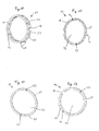
- FIG. 1 shows a first embodiment of the clock 1 according to the invention in a schematic sectional exploded view.
- the clock 1 has a housing 2, in which the movement 3 can be arranged, wherein the movement 3 is connected to a dial 4.
- On a front side 5 of the dial 4 at least one pointer 6 is arranged, which is operatively connected to the movement 3.
- the movement 3 is arranged on a rear side 7 of the dial 4.
- On a back 8 of the movement 3, a flywheel 9 may be arranged, which can operate, for example, an automatic elevator of a mechanical movement.
- a receiving opening 11 is further provided on a peripheral peripheral side 10, in which an optional rod-like structure 12 can protrude.
- the rod-like structure 12 is preferably connected to a crown 13 and may form approximately an elevator shaft or the extension of a push button. However, it is also possible to use movements 3 without a rod-like structure or with a plurality of rod-like structures. It is also possible to use electrically operated or electronic movements instead of a mechanical movement.
- a socket portion 15 with a receiving opening 16 forms part of a holder for a watch glass 17.
- a bezel 19 may be provided on the socket portion 15.
- An outer peripheral side 18 of the socket portion 15 may be offset from the other housing 2 and made narrower to accommodate such optional bezel 19 thereon.
- an interior 20 is provided, which may be formed in this example as a cylindrical bore. At least part of an inner cylindrical surface 21 of the inner space 20 is provided with an internal thread 22 in this embodiment. At a the socket portion 15 facing the end of the interior 20, a shoulder 23 is formed.
- the clock 1 also has a fastening means 24.
- this is formed as a ring with an external thread 25 which is provided on an outer periphery of the fastening means 24.
- the fastening means 24 further comprises a plurality, but at least one omission 26, which can be at least partially penetrated by the rod-like structure 12 in a fastened position, or at least partially surround the rod-like structure 12.
- the external thread 25 is formed so that it can be screwed into the internal thread 22 of the housing 2.
- the fastening means 24 is in FIG. 1 shown in a released position in which the dial 4 is released, so to speak.
- a housing cover 27 with an annular projection 28 is provided to close the inner space 20 at a rear side 29 of the housing 2.
- an external thread 30 is formed, which is screwed into the internal thread 22 of the housing 2.
- the housing cover 27 has an annular projection 28 adjacent flange 31, which abuts in a fixed position on the back 29 of the housing 2. Between the flange 31 and the housing 2 may possibly be provided a sealing element. It is also conceivable in all embodiments to provide in the interior 20 a shoulder and a second internal thread, which has a larger nominal diameter, than the nominal diameter of the region of the inner space or the internal thread, in which the fastening means 24 is provided. In such a larger internal thread then the housing cover 27 may be provided.
- FIG. 2 shows the exemplary embodiment of the clock FIG. 1 but assembled and in the fastened position in which the fastener 24 is mounted in the housing 2.
- the dial 4 rests against the shoulder 23 of the housing 2 within the interior space 20 and thus is in an abutment position.
- the fastening means 24 is screwed into the internal thread 22 of the inner cylindrical surface 21, is in this case on the dial 4, so that the dial 4 is fixed relative to the housing 2.
- the housing cover 27 closes the inner space 20 on one side of the housing 2, in this case on the rear side 29 of the housing 2.
- the watch glass 17 is received in the receiving opening 16 of the socket portion 15 and fixed therein.
- the optional bezel 19 is mounted on the socket portion 15 and surrounds it laterally and partially on a front side 32 of the housing 2.
- FIG. 3 shows a second exemplary embodiment of a clock, wherein in addition to the fastening means 24 a pressure transmission means 33 between the dial 4 and the fastening means 24 is provided.
- the pressure transmission means 33 which separately in the FIG. 7 is again shown, is approximately annular and here has at least one projection 34, as well as an executed as an interruption omission 35 for a rod-like structure 12. Instead of an interruption, a bore or taper can also be provided.
- the fastening means 24 and the pressure-transmitting means 33 can also be designed so that they are arranged in the fastened position between the dial 4 and the rod-like structure 12, so that both means can be carried out continuously.
- the dial 4 may be rotatably formed in all the embodiments described herein opposite to the housing 2, such as by the provision of a nose 51 which can engage in the housing 2. It is also conceivable that a part of the housing 2 engages the dial 4, or that the dial 4 is held in a rotationally fixed manner at its shoulder 23 in a form-fitting manner.
- the pressure-transmitting means 33 In the fastened position, the pressure-transmitting means 33 is held under spring bias between the fastening means 24 and the dial 4, wherein at least one of said components is designed to be prestressed for this purpose.
- the pressure transmitting means 33 may be resiliently designed to be biased in the fastened position relative to the dial 4.
- the disclosed watch may be, in particular, a wristwatch with a wrist band connection portion 37.
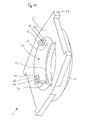
- FIG. 4 shows a schematic exploded perspective view of the second exemplary embodiment, looking substantially at the back 29 of the housing 2. It can be seen that the lugs 34 arranged at an angular distance of approximately 90 ° on the contact pressure transmission means 33 will engage in the identically arranged guide grooves 36 on the housing 2 when the clock 1 is assembled.
- the guide grooves 36 are also arranged at an angular distance of approximately 90 ° to the receiving opening 11 of the housing 2.
- FIG. 5 shows a further, third exemplary embodiment of the invention, in addition to the previously described embodiments, a clamping means 38 provides.
- the tensioning means 38 can, as in FIG. 5 shown, between the fastening means 24 and the Anvikübertragungsstoff 33 may be arranged, but also conceivable between the An fürübertragungsstoff 33 and the dial 4.
- the clamping means 38 is resilient and may be about a spring ring by means of which a resilient bias in the fastened position can be applied , One possible embodiment of such a ring is in the FIGS. 15 and 16 shown. In the FIGS. 15 and 16 a clamping means 38 is shown, which is designed as a kind of spring ring.
- the ring is constructed of a number of arcuate portions 49, which are connected to each other at the bow ends 50.
- the bow ends 50 can serve in the fastened position as a bearing surface for the fastening means 24, the pressure transmission means 33 or the dial 4, wherein the arcuate sections 49 serve as a support for the corresponding opposite fastening means 24, Anlichübertragungsstoff 33 or dial 4.
- clamping means 38 may additionally comprise at least one projection 40 which presses the movement 3 in the direction of paragraph 23 in a fixed position.
- at least one corresponding recess 39 may be provided, in which the at least one projection 40 can engage. This can provide additional stability of the dial 4 and the movement attached thereto.
- an exemplary fastener 24 is shown which may be used in particular in the first embodiment shown above.
- at least one planar flange surface 41 may be provided on the fastening means 24 in order to ensure as uniform a pressure as possible on the underlying elements.
- tool engagements 42 are provided, in which a part of a tool can be used to release the fastener. These tool engagements may be formed as a blind hole or through hole, but need not be cylindrical.
- the fastener in FIG. 6 is annular and has an inner bore 43 to receive components such as the movement 3 in the mounted position. Such an inner bore 43 may also preferably be present on the pressure-transmitting transmission means 33 and the tensioning means 38 if they are of annular design.
- FIG. 7 shows a variant of a pressure transmission means 33, which can be used in particular in the second exemplary embodiment and a fourth embodiment shown below.
- FIG. 8 shows an alternative fastening means 24 associated with the embodiment shown in FIG. 14 ,
- the fastening means has, instead of an external thread 25, at least one locking lug 44, which points radially outward.
- FIG. 9 shows a clamping means 38, which in this example has at least two lugs 40, which are formed pointing radially inwards to engage in a movement.
- FIG. 10 shows a fastening means 24 in which provided on a jacket-shaped outer surface 45 slot-like omissions 26 through which approximately a rod-like structure 12 can protrude in a fixed position.
- FIG. 10 shows a plurality of omissions 26, which are arranged radially over the circumference of the annular fastening means 24. In this way, a plurality of rod-like structures 12 may penetrate the fastener 24 simultaneously in different directions and / or the fastener may be rotated to different positions to still provide a passageway for the rod-like structure 12.
- fastening means 24 also has a plurality of omissions 26.
- the fastener 24 in the FIG. 11 from the fastener of the FIG. 10 derived.
- the FIG. 11 can be understood that the fastener from the FIG. 10 sliced or halved along a peripheral side. This can be used to accommodate the fastener in smaller receiving openings 11 of a housing 2.
- the fastener from the FIG. 10 In particular, it may be used to mechanically tighten the fastener 24.
- fastening means 24 is formed particularly flat. This may be required, the fastener 24 between a rod-like structure 12 and the dial 4 should be arranged in the fastened position. Alternatively, it may be necessary that the fastening means 24 is formed particularly flat when a pressure transmission means 33 and / or an additional tensioning means 38 are provided in the clock 1.
- fastening means 24 is formed as a broken ring, in which the omission 26 forms the interruption of the ring.
- the rod-like structure 12 is guided in the fastened position.
- an external thread 25 is provided on the outside circumferentially.
- FIG. 14 a fourth exemplary embodiment is shown schematically in a perspective view.
- a kind of hinge connection / bayonet connection or latching closure is provided in this embodiment by which the fastening means 24 can be connected to the housing 2.
- a fastener is conveniently used, which is approximately in FIG. 8 is shown and has at least one locking lug 44.
- latching structures 46 are formed on the housing 2.
- the housing cover 27 can then be fastened to the housing 2 separately from the fastening means 24, wherein both a threaded connection, a previously described hinge connection / bayonet connection, latching closure or other connections are conceivable.
- the at least one latching structure 46 has a groove section 47 which extends approximately transversely to the guide groove 36 and into which a locking projection 44 of the fastening means 24 can be inserted.
- an additional undercut 48 may be present, in which a locking lug 44 can be latched. In this way, the latching structure 46 together with the fastening means 24 form a kind of latching or latching connection.
- the groove portion 47 and the additional providable undercut 48 may also be arcuate, so that the fastening means 24 form a kind of recessed connection or bayonet connection in the latching structure 46.
- fastener 24 may also be an additional snap-in structure that locks the fastener 24 in the fastened position.
- the receiving opening 11 has a continuous diameter, in which the fastening means 24 and the housing cover 27 are attached.
- the receiving space 11 may also be formed stepped, so that the outer diameter of the fastening means 24 and the housing cover 27 and its annular projection 28 may differ.
- the fastening means 24 may generally be provided in all embodiments of different materials and in different embodiments.
- the fastener may be made of a metal such as gold or platinum to serve as a carrier for decorations such as gems or engravings.
- the fastener could also be made of carbon or titanium to save weight.
- the assembly with the dial 4 and the movement 3 attached thereto from the back 29 of the housing 2 ago in the interior 20 of the housing 2 is inserted, so that the front side 5 of the dial 4 rests against the shoulder 23 of the housing 2 in the contact position.
- the fastening means 24 is then screwed into the housing 2, wherein the external thread 25 of the fastening means 24 engages in the internal thread 22 in the inner space 20.
- the fastening means 24 is screwed in until the flange 41 on the dial 4, that is resting on the back 7, and the dial 4 relative to the housing 2 determines. In this case, the dial 4 is pressed against the shoulder 23.
- the crown 13 is guided with the projecting rod-like structure 12, for example, an elevator shaft through the omission 14 in the housing 2 in the receiving opening 11 on the movement 3 and fixed in the movement 3.
- the housing cover 27 is also screwed into the internal thread 22 of the housing 2.
- a previously mentioned second internal thread could be provided on the housing 2, into which the housing cover 27 can be detachably screwed.
- the pressure-transmitting transmission means 33 and / or the tensioning means 38 are first placed on the dial 4 arranged in the housing 2.
- the pressure transmission means 33 and / or the tensioning means 38 surround the movement 3 at least partially. Subsequently, the fastening means 24 is mounted engaging in the housing 2.
- FIG. 14 instead of the threaded connection can also in FIG. 14 be shown locking connection or a recessed joint given as long as the housing 2 and the fastening means 24 engage.
- the screwing of the fastener 24 is replaced by an insertion of the locking lugs 44 in the guide grooves on the housing 2, followed by a rotation of the fastener 24 until each locking lug 44 is inserted through the corresponding groove portion 47 in the latching structure 46 and in the undercut 48th locks.
- Also provided on the dial 4 nose 51 can counteract the rotational movement of the fastener 24 by engaging with the housing 2.
Landscapes
- Physics & Mathematics (AREA)
- General Physics & Mathematics (AREA)
- Electric Clocks (AREA)
- Electromechanical Clocks (AREA)
Abstract
Description
Die Erfindung bezieht sich auf eine Uhr mit den Merkmalen des Oberbegriffs des Anspruches 1.The invention relates to a timepiece having the features of the preamble of claim 1.
Es ist bekannt in Uhren ein Uhrwerk vorzusehen, welches mit drehbaren Zeigern verbunden ist, um die Uhrzeit auf einem Zifferblatt anzuzeigen.It is known in watches to provide a movement which is connected to rotating hands to indicate the time on a dial.
Aus der
In einer davon verschiedenen Konstruktion wird das Zifferblatt als tragendes Teil absichtlich gegen einen Teil des Uhrengehäuses gedrückt. Das Zifferblatt ist darin in dem Uhrengehäuse angeordnet und liegt in einer Anlagestellung an dem Gehäuse an. Zur Befestigung des Zifferblattes mit dem Uhrwerk in dem Uhrengehäuse werden Laschen zu verwendet, welche mit einer Grundplatine des Uhrwerks verschraubt sind und sich seitlich auswärts an dem Uhrengehäuse abstützen.In a different construction, the dial is deliberately pressed against a part of the watch case as a supporting part. The dial is disposed therein in the watch case and abuts in an abutment position on the housing. To attach the dial with the clock in the watch case tabs are used, which are bolted to a motherboard of the movement and laterally supported on the outside of the watch case.
Die Laschen sind gegenüber dem übrigen Uhrwerk relativ klein und dünn und stehen andauernd unter Spannung. Dies führt zu einer Verschleiß- und Bruchgefährdung der Laschen. Insbesondere bei Armbanduhren kann während des Tragens ein Materialverschleiß oder Materialbruch auftreten, wenn das Uhrwerk mittels solcher Laschen befestigt wird. Oftmals brechen diese Laschen unvorhergesehen auch bei Uhren, die keinen besonderen Belastungen ausgesetzt sind. Aus diesen Gründen werden jene Laschen bei einer Wartung der Uhr gewöhnlich gegen neue Laschen vorbeugend ausgetauscht.The tabs are relatively small and thin compared to the rest of the movement and are constantly under tension. This leads to a risk of wear and breakage of the tabs. In particular wristwatches, material wear or material breakage may occur during wear when the movement is fastened by means of such tabs. Often, these flaps break unforeseen even in watches that are not exposed to any special stress. For these reasons, those tabs are usually replaced preventively against new tabs when the watch is serviced.
Die Laschen werden gewöhnlich mittels kleiner Schrauben auf das Uhrwerk aufgeschraubt. Dabei kann es mitunter zu einem Bruch der Schraube in dem an der Grundplatine des Uhrwerks vorgesehenen Gewinde kommen, so dass eine solche Schraube ausgebohrt, und das Gewinde nachgeschnitten werden muss. In ungünstigen Fällen muss eine völlig neue Grundplatine für das Uhrwerk verwendet werden, wenn ein Ausbohren der Schraube und ein Nachschneiden des Gewindes nicht möglich ist. Dies führt zu einem sehr hohen Kosten- und Zeitaufwand.The tabs are usually screwed by means of small screws on the clockwork. It can sometimes lead to a fracture of the screw in the motherboard of the movement provided thread, so that such a screw drilled out, and the thread must be recut. In unfavorable cases, a completely new master plate must be used for the movement, if a drilling out of the screw and a re-cutting of the thread is not possible. This leads to a very high cost and time.
Insbesondere trifft dies bei Armbanduhren zu, für die eine Herstellung feinmechanischer Komponenten notwendig sein kann. Ein weiteres Problem einer solchen feinmechanischen Lösung kann durch ein schiefes Einschrauben einer Schraube in die Grundplatine eintreten, welches auch Cross-Threading genannt wird. Dabei wird die Schraube schräg zu der Bohrung angesetzt und schräg eingeschraubt, so dass einzelne Gewindegänge beschädigt werden.In particular, this applies to wristwatches, for which a production of fine mechanical components may be necessary. Another problem of such a fine mechanical solution can occur by an oblique screwing a screw into the motherboard, which is also called cross-threading. The screw is set at an angle to the hole and screwed at an angle, so that individual threads are damaged.
Bei einer gattungsgemäßen Uhr wird ein Werkhaltering in das Uhrengehäuse eingelegt, welcher das Uhrwerk umgibt und auf dem Zifferblatt aufliegt. Der Werkhaltering kann dann mittels eines in das Gehäuse eingesetzten Gehäusedeckels im Gehäuse festgepresst werden, wodurch das Zifferblatt und das an dem Zifferblatt gehaltene Uhrwerk gegenüber dem Gehäuse festgelegt werden.In a generic watch a Werkhaltering is inserted into the watch case, which surrounds the movement and rests on the dial. The Werkhaltering can then be pressed by means of a housing cover inserted into the housing in the housing, whereby the dial and held on the dial clockwork are fixed relative to the housing.
Bei einem Andrücken des Werkhalterings mittels eines Gehäusedeckels ist es erforderlich, die einzelnen Komponenten äußerst präzise und damit kostenaufwendig zu fertigen. Wenn der Werkhaltering zu dick gefertigt ist, kann der Gehäusedeckel nicht vollständig in das Gehäuse eingeschraubt werden und an diesem dicht anliegen, so dass das Uhrengehäuse möglicherweise nicht wasserdicht wird. Der Gehäusedeckel kann daher unbeabsichtigt so fest in das Uhrengehäuse eingeschraubt werden, dass der Werkhaltering zu fest auf das Zifferblatt drückt und dieses beschädigt. Sollte der Werkhaltering zu dünn gefertigt sein kann es vorkommen, dass der Gehäusedeckel bereits an dem Gehäuse dichtend anliegt, bevor das Zifferblatt sicher in das Gehäuse gedrückt wird. So kann möglicherweise kein ausreichender Anpressdruck zwischen Gehäusedeckel und Zifferblatt aufgebaut werden, so dass das Zifferblatt und das Uhrwerk nicht ausreichend in dem Gehäuse befestigt werden können.When pressing the Werkhalterings by means of a housing cover, it is necessary to manufacture the individual components extremely precise and therefore costly. If the retainer ring is made too thick, the housing cover may not be fully screwed into and tight with the housing so that the watch case may not be watertight. The housing cover can therefore be inadvertently screwed so tightly into the watch case that the Werkhaltering presses too hard on the dial and this damaged. If the movement retaining ring is made too thin, it may happen that the housing cover is already sealing against the housing before the dial is pressed securely into the housing. So may not be sufficient pressure between the housing cover and dial are built so that the dial and the clockwork can not be sufficiently secured in the housing.
Beim Einschrauben des Gehäusedeckels kann weiterhin meist nicht gleichzeitig beobachtet werden, wie sich die in dem Uhrengehäuse befindlichen Bauteile verhalten, so dass der Montagevorgang weniger exakt steuerbar ist.When screwing in the housing cover, furthermore, it is generally not possible at the same time to observe how the components in the watch case behave, so that the assembly process can be controlled less precisely.
Der Erfindung liegt die Aufgabe zugrunde eine Uhr der eingangs genannten Gattung zu schaffen, die trotz eines einfachen Aufbaus die Befestigung des Zifferblattes und des Uhrwerkes innerhalb des Uhrgehäuses verbessert, sowie eine einfache und sichere Montage ermöglicht.The invention has for its object to provide a clock of the type mentioned, which improves the attachment of the dial and the movement within the watch case despite a simple construction, and allows easy and safe installation.
Die Aufgabe wird erfindungsgemäß durch eine gattungsgemäße Uhr gelöst, bei der ein zu dem Gehäusedeckel separat ausgebildetes mit dem Gehäuse in Eingriff stehendes Befestigungsmittel in der Anlagestellung das Zifferblatt gegenüber dem Gehäuse festlegt.The object is achieved by a generic watch in which a separately formed to the housing cover with the housing engaged fastening means in the contact position determines the dial relative to the housing.
Das Befestigungsmittel kann auf diese Weise das Zifferblatt und das damit verbundene Uhrwerk in dem Gehäuse festlegen bevor der separat dazu ausgebildete Gehäusedeckel mit dem Gehäuse verbunden wird, um dieses zu verschließen. Der Andruck des Zifferblattes an das Gehäuse kann auf diese Weise unabhängig von dem separaten Gehäusedeckel festgelegt werden, so dass die Beschädigung des Zifferblattes weniger wahrscheinlich wird, das Zifferblatt aber dennoch ausreichend fest in dem Gehäuse gehalten wird. Aufgrund der separaten Ausbildung von Befestigungsmittel und Gehäusedeckel kann es möglich sein, zunächst das Zifferblatt mit Hilfe des Befestigungsmittels in dem Gehäuse festzulegen, bevor der Gehäusedeckel auf das Gehäuse aufgesetzt wird. Dies kann ermöglichen, das Zifferblatt und weitere Komponenten während des Montierens zu beobachten.The fastener can set in this way the dial and the associated movement in the housing before the separately formed housing cover is connected to the housing to close it. The pressure of the dial to the housing can be fixed in this way regardless of the separate housing cover, so that the damage of the dial is less likely, but the dial is still sufficiently firmly held in the housing. Due to the separate design of fastener and housing cover, it may be possible to first set the dial by means of the fastener in the housing before the housing cover is placed on the housing. This may allow to observe the dial and other components during mounting.
Vorstellbar kann das Befestigungsmittel aus einer gelösten, das Zifferblatt freigebenden Stellung in eine befestigte Stellung drehbar sein, in welcher das Zifferblatt in der Anlagestellung gehalten ist. Auf diese Weise kann eine einfache Montage des Befestigungsmittels ermöglicht werden.Conceivably, the fastener may be rotatable from a released, the dial releasing position in a fixed position in which the dial is held in the contact position. In this way, a simple mounting of the fastener can be made possible.
In einer Variante der Erfindung kann das Befestigungsmittel wenigstens einen Teil des Uhrwerkes etwa ringartig umgeben und relativ zu dem Uhrwerk und dem Zifferblatt drehbar sein. Der Raum zwischen dem Uhrwerk und dem Gehäuse kann auf diese Weise effizient ausgenutzt werden.In a variant of the invention, the fastening means may surround at least a part of the movement in an annular manner and be rotatable relative to the movement and the dial. The space between the movement and the housing can be efficiently used in this way.
In einer Variante der Erfindung kann das Befestigungsmittel mittels eines Gewindes in das Gehäuse eingreifen. Das Befestigungsmittel kann mittels des Gewindes auf einfache Weise an dem Gehäuse befestigt und von diesem wieder möglicherweise gelöst werden, um etwa eine Wartung oder Reparatur zu ermöglichen.In a variant of the invention, the fastening means can engage in the housing by means of a thread. The fastener can be easily attached to the housing by means of the thread and possibly loosened therefrom again, in order to allow maintenance or repair.
Es wird vorgeschlagen, dass der Eingriff zwischen dem Gehäuse und dem Befestigungsmittel eine Renkverbindung oder eine bajonettartige Verbindung aufweist. Renkverbindungen bzw. bajonettartige Verbindungen sind einfach zwischen dem Gehäuse und dem Befestigungsmittel vorzusehen. Ferner können solche Verbindungsarten auf einfache Weise, durch Drücken und Drehen, gelöst und wieder befestigt werden.It is proposed that the engagement between the housing and the fastening means comprise a recessed connection or a bayonet-type connection. Reverse connections or bayonet-type connections are easy to provide between the housing and the fastening means. Furthermore, such types of connection can be easily solved by pressing and turning, and fixed again.
Vorstellbar kann der Eingriff zwischen dem Gehäuse und dem Befestigungsmittel einen Rastverschluss aufweisen. Dies kann vorteilhaft sein, wenn etwa die Möglichkeit eines selbständigen Lösens des Befestigungsmittels verringert werden soll. Ferner kann ein Rastverschluss eine gut wahrnehmbare Rückmeldung darüber geben, dass das Befestigungsmittel eine befestigte Stellung erreicht hat.Conceivably, the engagement between the housing and the fastening means may comprise a latching closure. This can be advantageous if, for example, the possibility of an independent release of the fastening means is to be reduced. Further, a snap lock can give a well-perceptible feedback that the fastener has reached a fastened position.
In einer Variante der Erfindung kann wenigstens eine stabartige Struktur an der Uhr vorgesehen sein, welche durch das Gehäuse hindurch in das Uhrwerk ragt, und das Befestigungsmittel in der Anlagestellung zwischen dem Zifferblatt und der stabartigen Struktur angeordnet ist. Eine solche stabartige Struktur kann etwa eine Aufzugwelle sein, welche mit einer außenseitig angebrachten Krone verbunden ist. Alternativ kann ein Druckstab vorgesehen sein, welcher eine Druckbewegung auf einen außenseitigen Druckknopf in das Uhrwerk überträgt. Das vorteilhafter Weise zwischen dem Zifferblatt und der stabartigen Struktur angeordnete Befestigungsmittel kann so auf einfache konstruktionelle Weise ausgeführt sein.In a variant of the invention, at least one rod-like structure may be provided on the clock, which protrudes through the housing into the movement, and the fastening means is arranged in the contact position between the dial and the rod-like structure. Such a rod-like structure may be, for example, an elevator shaft, which is connected to an externally mounted crown. Alternatively, a push rod may be provided, which transmits a pressure movement on an outside push button in the movement. The advantageously arranged between the dial and the rod-like structure fastening means can be designed in a simple construction way.
In einer Variante der Erfindung kann wenigstens eine stabartige Struktur an der Uhr vorgesehen sein, welche durch das Gehäuse hindurch in das Uhrwerk ragt, und das Befestigungsmittel in der befestigten Stellung auf einer dem Zifferblatt abgewandten Seite der stabartigen Struktur angeordnet sein. Die stabartige Struktur kann so auf einfache Weise an dem Befestigungsmittel vorbeigeführt werden, um in das Uhrwerk hineinzuragen. Dies kann den inneren Aufbau der Uhr vereinfachen.In a variant of the invention, at least one rod-like structure may be provided on the watch which protrudes through the housing into the movement, and the fastening means may be arranged in the fastened position on a side of the rod-like structure facing away from the dial. The rod-like structure can thus be passed easily past the fastening means in order to project into the movement. This can simplify the internal structure of the clock.
Vorstellbar kann wenigstens eine stabartige Struktur an der Uhr vorgesehen sein, welche durch das Gehäuse hindurch in das Uhrwerk ragt, wobei wenigstens ein Teil des Befestigungselementes die stabartige Struktur wenigstens teilweise umgibt. Die stabartige Struktur kann dabei das Befestigungselement wenigstens teilweise durchdringen. Auf diese Weise kann das Befestigungselement relativ dick und stabil ausgebildet werden und die stabartige Struktur dennoch in das Uhrwerk geführt werden.It is conceivable that at least one rod-like structure may be provided on the watch, which protrudes through the housing into the movement, wherein at least part of the fastening element at least partially surrounds the rod-like structure. The rod-like structure can thereby at least partially penetrate the fastening element. In this way, the fastener can be made relatively thick and stable and the rod-like structure can still be performed in the movement.
Vorstellbar kann ein Andruckübertragungsmittel zwischen dem Zifferblatt und dem Befestigungsmittel angeordnet sein. Ein Andruckübertragungsmittel kann auf diese Weise als eine Art Abstandshalter wirken, so dass das Befestigungsmittel zu dem Zifferblatt beabstandet angeordnet ist, wenn dies für die Anordnung der Komponenten in der Uhr vorteilhaft ist.It is conceivable that a contact pressure transmission means can be arranged between the dial and the fastening means. A pressure transmitting means may in this way act as a kind of spacer, so that the fastening means is arranged spaced from the dial, if this is advantageous for the arrangement of the components in the clock.
In einer bevorzugten Ausführungsform kann das Befestigungsmittel und/oder das Andruckübertragungsmittel ringartig ausgebildet sein. Dies kann den Andruck auf das Zifferblatt vergleichmäßigen und damit die Gefahr einer Beschädigung des Zifferblattes bei einem Befestigen des Befestigungsmittels verringern. Ferner kann eine ringartige Ausbildung des Befestigungsmittels und/oder des Andruckübertragungsmittels die Herstellung dieser Mittel vereinfachen.In a preferred embodiment, the fastening means and / or the Andruckübertragungsmittel may be formed annular. This can equalize the pressure on the dial and thus reduce the risk of damage to the dial when attaching the fastener. Furthermore, a ring-like design of the fastener and / or the Andruckübertragungsmittels simplify the preparation of these means.
Möglicherweise kann das Andruckübertragungsmittel in einer befestigten Stellung des Befestigungsmittels unter federnder Vorspannung gehalten sein. Auf diese Weise kann das Zifferblatt sicher in dem Gehäuse gehalten werden und die Wahrscheinlichkeit eines selbsttätigen Lösens des Befestigungsmittels einfach verringert werden.Possibly, the pressure-transmitting means may be held in a fixed position of the fastening means under resilient bias. In this way, the dial can be held securely in the housing and the likelihood of self-loosening of the fastener can be easily reduced.
In einer Variante der Erfindung kann das Andruckübertragungsmittel federnd nachgebend ausgebildet sein. Auf diese Weise kann eine federnde Vorspannung durch ein Verformen des Andruckübertragungsmittels aufgebaut werden, um das Zifferblatt sicher in dem Gehäuse zu halten. Durch die federnd nachgebende Ausbildung des Andruckübertragungsmittels kann eine Nachgiebigkeit für die federnde Vorspannung einfach eingestellt werden.In a variant of the invention, the contact pressure transmission means may be formed resiliently yielding. In this way, a resilient bias can be built by deforming the Andruckübertragungsmittels to keep the dial safely in the housing. Due to the resiliently yielding design of the pressure-transmitting means, a compliance for the resilient bias can be easily adjusted.
Denkbar kann das Andruckübertragungsmittel und/oder das Befestigungsmittel eine Unterbrechung aufweisen, welche in der Anlagestellung bzw. der befestigten Stellung einen Durchgang für eine stabartige Struktur freigibt, welche durch das Gehäuse hindurch in das Uhrwerk ragt. Dies kann eine besonders einfache Ausbildung sein, welche das Durchragen einer stabartigen Struktur in das Uhrwerk erlaubt. Eine solche Ausbildung kann die Fertigung des Andruckübertragungsmittels oder des Befestigungsmittels vereinfachen.Conveniently, the contact pressure transmission means and / or the fastening means may have an interruption, which releases a passage for a rod-like structure in the contact position or the fixed position, which protrudes through the housing into the movement. This can be a particularly simple design, which allows the passage of a rod-like structure in the movement. Such a design can simplify the manufacture of the pressure-transmitting means or the fastening means.
In besonderer Weise kann zwischen dem Zifferblatt und dem Andruckübertragungsmittel und/oder zwischen dem Andruckübertragungsmittel und dem Befestigungsmittel wenigstens ein federnd nachgiebiges Spannmittel vorgesehen sein, welches das Befestigungsmittel in der befestigten Stellung gegenüber dem Zifferblatt vorspannt. So kann auf einfache Weise eine definierte Andruckkraft auf das Zifferblatt aufgebaut werden, welche insbesondere gleichmäßig verteilt werden kann. Weiterhin kann eine solche Ausgestaltung erlauben, das Andruckübertragungsmittel und/oder das Befestigungsmittel relativ stabil auszuführen.In a special way, at least one resilient clamping means may be provided between the dial and the pressure-transmitting means and / or between the pressure-transmitting means and the fastening means, which means the fastening means biased in the fastened position relative to the dial. Thus, a defined pressure force on the dial can be constructed in a simple manner, which in particular can be distributed evenly. Furthermore, such a configuration may allow the pressure-transmitting means and / or the fastening means to be made relatively stable.
Denkbar kann das Spannmittel das Uhrwerk in der befestigten Stellung wenigstens teilweise umgeben. So kann der verfügbare Raum zwischen dem Uhrwerk und dem Gehäuse gut und effizient ausgenutzt werden.Conveniently, the tensioning means can at least partially surround the movement in the fastened position. Thus, the available space between the movement and the housing can be used well and efficiently.
Möglicherweise kann das Spannelement wenigstens einen Abschnitt aufweisen, welcher sich mit dem Uhrwerk in Eingriff befindet, und das Uhrwerk zusätzlich gegenüber dem Gehäuse in der Anlagestellung festlegt oder in die Anlagestellung vorspannt. Mit einer solchen Ausbildung kann einerseits eine zusätzliche Haltekraft auf das Uhrwerk ausgeübt werden, um das Uhrwerk besser in dem Gehäuse zu halten. Andererseits können Aussparungen an einem Uhrwerk zum Halten ergänzend ausgenutzt werden, welche ansonsten durch herkömmliche Haltelaschen eingenommen würden, so dass gegebenenfalls darin befindliche Borungen abgedeckt werden können.Possibly, the clamping element may have at least one portion which is in engagement with the movement, and additionally sets the movement in relation to the housing in the contact position or biases it into the contact position. With such a design, on the one hand, an additional holding force can be exerted on the movement in order to better hold the movement in the housing. On the other hand, recesses can be used in addition to a clockwork for holding, which would otherwise be occupied by conventional retaining tabs, so that any bungs therein can be covered.
In einer bevorzugten Ausführungsform kann das Zifferblatt gegenüber dem Gehäuse verdrehfest vorgesehen sein. Das Zifferblatt kann so bei der Montage in eine definierte Lage gebracht werden, die es während der darauffolgenden Montage des Befestigungsmittels beibehält, insbesondere wenn das Befestigungsmittel in eine befestigte Stellung drehbar ist und das Drehen teilweise auf das Zifferblatt übertragen wird.In a preferred embodiment, the dial can be provided against rotation relative to the housing. The dial can thus be brought to a defined position during assembly, which it maintains during the subsequent mounting of the fastener, in particular when the fastener is rotatable to a fixed position and the rotation is partially transmitted to the dial.
Zweckmäßigerweise kann das Zifferblatt durch ein Eingreifen gegenüber dem Gehäuse verdrehfest vorgesehen sein. Dies kann den Zusammenbau der erfindungsgemäßen Uhr vereinfachen. Beispielsweise können an dem Gehäuse oder dem Zifferblatt Ansätze vorgesehen sein, welche in Aussparungen an dem Zifferblatt oder dem Gehäuse eingreifen. Dies kann eine Montage des Zifferblattes vereinfachen, da es dessen Ausrichtung gegenüber dem Gehäuse beibehält.Appropriately, the dial can be provided by an engagement with respect to the housing rotationally. This can simplify the assembly of the clock according to the invention. For example, projections may be provided on the housing or dial which engage recesses on the dial or housing. This can simplify mounting of the dial as it maintains its alignment with the housing.
Es wird vorgeschlagen, dass das Andruckübertragungsmittel, insbesondere durch ein Eingreifen, verdrehfest gegenüber dem Gehäuse vorgesehen ist. Auf diese Weise ist es möglich, montagebedingte Beschädigungen an dem Zifferblatt und anderen Teilen der Uhr zu vermindern, da das Andruckübertragungsmittel während der Montage und danach im Wesentlichen in einer vorgegebenen Position gehalten werden kann, und die Drehung des Befestigungsmittels wenig oder gar nicht auf das Zifferblatt überträgt. Günstigerweise könnte das Befestigungsmittel und/oder der Gehäusedeckel in der befestigten Stellung in das Gehäuse eingeschraubt sein. Dies kann eine einfache und unkomplizierte Montage erlauben.It is proposed that the contact pressure transmission means, in particular by an intervention, is provided rotationally fixed relative to the housing. In this way, it is possible to reduce assembly-related damage to the dial and other parts of the clock, since the Andruckübertragungsmittel during assembly and after can be held substantially in a predetermined position, and transmits the rotation of the fastener little or not on the dial. Conveniently, the fastening means and / or the housing cover could be screwed into the housing in the fastened position. This can allow a simple and uncomplicated installation.
Vorzugsweise kann in dem Innenraum wenigstens ein Innengewinde vorgesehen sein, in welches sowohl das Befestigungsmittel, als auch der Gehäusedeckel einschraubbar sind. Eine solche Ausführungsform erlaubt, einen Eingriff des Befestigungsmittels in das Gehäuse und des Gehäusedeckels in das Gehäuse einfach vorzusehen. Möglicherweise kann dabei sogar das Befestigungsmittel in dasselbe Gewinde eingeschraubt werden, in das ebenfalls der Gehäusedeckel eingeschraubt ist.Preferably, at least one internal thread can be provided in the interior space, into which both the fastening means and the housing cover can be screwed. Such an embodiment allows to easily provide an engagement of the fastener in the housing and the housing cover in the housing. Possibly even the fastening means can be screwed into the same thread, in which the housing cover is also screwed.
In einer Variante der Erfindung kann für das Befestigungsmittel ein erster Gewindeabschnitt mit einem ersten Nenndurchmesser, sowie ein zweiter Gewindeabschnitt mit einem zweiten Nenndurchmesser für den Gehäusedeckel vorgesehen sein. Dies kann erlauben, dass die Größe des Zifferblattes unabhängig von der Größe des Gehäusedeckels gewählt werden kann und somit die Gehäusedimensionen und die Zifferblattdimensionen im Wesentlichen unabhängig voneinander variiert werden können.In a variant of the invention may be provided for the fastening means a first threaded portion having a first nominal diameter, and a second threaded portion having a second nominal diameter for the housing cover. This may allow the size of the dial to be chosen independently of the size of the case cover, and hence the case dimensions and dial dimensions to be varied substantially independently of each other.
Vorstellbar kann der Gehäusedeckel in ein Innengewinde des Gehäuses eingeschraubt sein, und in dem Innengewinde wenigstens eine Auslassung vorgesehen sein, in die das Befestigungsmittel einrastbar ist. Auf diese Weise lassen sich die Vorteile eines eingeschraubten Gehäusedeckels, sowie die Vorteile eines einzurastenden Befestigungsmittels kombinieren.Conceivable, the housing cover can be screwed into an internal thread of the housing, and be provided in the internal thread at least one omission, in which the fastening means can be latched. In this way, the advantages of a screwed-housing cover, as well as the advantages of a fastener to be locked can be combined.
Beispielhafte Ausführungsformen der Erfindung sind in der Zeichnung dargestellt und werden nachstehend erläutert.Exemplary embodiments of the invention are illustrated in the drawings and will be explained below.
Es zeigen:
- Figur 1
- eine schematische seitliche geschnittene Explosionsansicht einer ersten beispielhaften Ausführungsform,
Figur 2- eine schematische seitliche Schnittansicht der ersten Ausführungsform der erfindungsgemäßen Uhr,
Figur 3- eine schematische perspektivische Explosionsansicht einer zweiten beispielhaften Ausführungsform,
Figur 4- eine rückwärtige schematische perspektivische Explosionsansicht der zweiten beispielhaften Ausführungsform,
Figur 5- eine schematische perspektivische Explosionsansicht einer beispielhaften dritten Ausführungsform der Erfindung,
Figur 6- eine schematische perspektivische Ansicht einer beispielhaften Variante des Befestigungsmittels,
Figur 7- eine schematische Ansicht einer beispielhaften Variante eines Andruckübertragungsmittels,
Figur 8- eine schematische Ansicht einer beispielhaften Variante eines Befestigungsmittels,
Figur 9- eine schematische Ansicht einer beispielhaften Variante eines Spannmittels,
Figur 10- eine schematische Ansicht einer beispielhaften Variante des Befestigungsmittels,
Figur 11- eine schematische perspektivische Ansicht einer weiteren beispielhaften Variante des Befestigungsmittels,
Figur 12- eine schematische Ansicht einer weiteren beispielhaften Variante des Befestigungsmittels,
Figur 13- eine schematische Ansicht einer weiteren beispielhaften Variante des Befestigungsmittels,
Figur 14- eine schematische perspektivische Ansicht eines Gehäuses gemäß einer vierten beispielhaften Ausführungsform, und
Figur 15 und 16- je eine schematische Ansicht eines beispielhaften Spannmittels.
- FIG. 1
- 1 is a schematic side sectional exploded view of a first exemplary embodiment,
- FIG. 2
- a schematic sectional side view of the first embodiment of the clock according to the invention,
- FIG. 3
- 3 is a schematic exploded perspective view of a second exemplary embodiment,
- FIG. 4
- 10 is a rear schematic exploded perspective view of the second exemplary embodiment;
- FIG. 5
- FIG. 3 is a schematic exploded perspective view of an exemplary third embodiment of the invention; FIG.
- FIG. 6
- a schematic perspective view of an exemplary variant of the fastening means,
- FIG. 7
- FIG. 2 a schematic view of an exemplary variant of a pressure-transmitting transmission means, FIG.
- FIG. 8
- a schematic view of an exemplary variant of a fastening means,
- FIG. 9
- a schematic view of an exemplary variant of a clamping means,
- FIG. 10
- a schematic view of an exemplary variant of the fastening means,
- FIG. 11
- a schematic perspective view of another exemplary variant of the fastening means,
- FIG. 12
- a schematic view of another exemplary variant of the fastening means,
- FIG. 13
- a schematic view of another exemplary variant of the fastening means,
- FIG. 14
- a schematic perspective view of a housing according to a fourth exemplary embodiment, and
- FIGS. 15 and 16
- each a schematic view of an exemplary clamping device.
An dem Gehäuse 2 ist zum Durchführen der stabartigen Struktur 12 eine Auslassung 14 vorgesehen, durch die die stabartige Struktur in einem zusammengebauten Zustand hindurchgeführt ist. Ein Fassungsabschnitt 15 mit einer Aufnahmeöffnung 16 bildet einen Teil einer Halterung für ein Uhrenglas 17. An dem Gehäuse 2 kann eine Lünette 19 an dem Fassungsabschnitt 15 vorgesehen sein. Eine äußere Umfangsseite 18 des Fassungsabschnittes 15 kann dazu gegenüber dem übrigen Gehäuse 2 abgesetzt und schmaler ausgebildet sein, um eine solche optionale Lünette 19 darauf aufzunehmen.Provided on the
Im Inneren des Gehäuses 2 ist ein Innenraum 20 vorgesehen, der in diesem Beispiel etwa als zylindrische Bohrung ausgebildet sein kann. Wenigstens ein Teil einer inneren Zylinderfläche 21 des Innenraums 20 ist in diesem Ausführungsbeispiel mit einem lnnengewinde 22 versehen. An einem dem Fassungsabschnitt 15 zugewandten Ende des Innenraums 20 ist ein Absatz 23 ausgebildet.In the interior of the
Die Uhr 1 weist ferner ein Befestigungsmittel 24 auf. In dem vorliegenden Ausführungsbeispiel ist dieses als Ring mit einem Außengewinde 25 ausgebildet, welches an einem äußeren Umfang des Befestigungsmittel 24 vorgesehen ist. Das Befestigungsmittel 24 weist ferner eine Vielzahl, jedoch wenigstens eine Auslassung 26 auf, welche in einer befestigten Stellung von der stabartigen Struktur 12 wenigstens teilweise durchdrungen werden können, bzw. welche die stabartige Struktur 12 wenigstens teilweise umgeben. Das Außengewinde 25 ist so ausgebildet, dass es in das Innengewinde 22 des Gehäuses 2 einschraubbar ist. Das Befestigungsmittel 24 ist in
Ein Gehäusedeckel 27 mit einem ringförmigen Ansatz 28 ist vorgesehen, um den Innenraum 20 an einer Rückseite 29 des Gehäuses 2 zu verschließen. An dem ringförmigen Ansatz 28 ist ein Außengewinde 30 ausgebildet, welches in das Innengewinde 22 des Gehäuses 2 einschraubbar ist. Der Gehäusedeckel 27 weist eine dem ringförmigen Ansatz 28 benachbarte Flanschfläche 31 auf, welche in einer befestigten Stellung auf der Rückseite 29 des Gehäuses 2 anliegt. Zwischen der Flanschfläche 31 und dem Gehäuse 2 kann möglicherweise ein Dichtelement vorgesehen sein. Es ist auch in allen Ausführungsformen denkbar, in dem Innenraum 20 einen Absatz und ein zweites Innengewinde vorzusehen, welches einen größeren Nenndurchmesser aufweist, als der Nenndurchmesser des Bereiches des Innenraumes oder des Innengewindes, in dem das Befestigungsmittel 24 vorgesehen ist. In einem solchen größeren Innengewinde kann dann der Gehäusedeckel 27 vorgesehen werden.A
Das Uhrenglas 17 ist in die Aufnahmeöffnung 16 des Fassungsabschnittes 15 aufgenommen und darin befestigt. Die optionale Lünette 19 ist auf dem Fassungsabschnitt 15 montiert und umgibt diesen seitlich und teilweise an einer Vorderseite 32 des Gehäuses 2.The
Das Andruckübertragungsmittel 33, welches separat in der
An dem Gehäuse 2, welches in der
In der befestigten Stellung ist das Andruckübertragungsmittel 33 unter federnder Vorspannung zwischen dem Befestigungsmittel 24 und dem Zifferblatt 4 gehalten, wobei wenigstens eines der genannten Bauteile zu diesem Zwecke vorspannbar ausgebildet ist. Das Andruckübertragungsmittel 33 kann federnd nachgiebig ausgebildet sein, um in der befestigten Stellung gegenüber dem Zifferblatt 4 vorgespannt zu sein.In the fastened position, the pressure-transmitting
Aus der
Die
Das in der
In der
Das in
Das in
Das in
In
In dieser Ausführungsform wird günstigerweise ein Befestigungsmittel verwendet, welches etwa in
Die wenigstens eine Einraststruktur 46 weist einen zur Führungsnut 36 etwa quer verlaufenden Nutabschnitt 47 auf, in die ein Verriegelungsansatz 44 des Befestigungsmittels 24 einschiebbar ist. An dem Nutabschnitt 47 kann ein zusätzlicher Hinterschnitt 48 vorhanden sein, in den ein Verriegelungsansatz 44 einrastbar ist. Auf diese Weise kann die Einraststruktur 46 zusammen mit dem Befestigungsmittel 24 eine Art Einrast-, oder Rastverbindung bilden.The at least one latching
Der Nutabschnitt 47 und der zusätzliche vorsehbare Hinterschnitt 48 können auch bogenförmig ausgebildet sein, so dass das Befestigungsmittel 24 in die Einraststruktur 46 eine Art Renkverbindung oder Bajonettverbindung bilden.The groove portion 47 and the additional providable undercut 48 may also be arcuate, so that the fastening means 24 form a kind of recessed connection or bayonet connection in the latching
In den Ausführungsbeispielen, bei denen das Befestigungsmittel 24 in das Gehäuse eingeschraubt wird kann auch eine zusätzliche Einraststruktur vorhanden sein, die das Befestigungsmittel 24 in der befestigten Stellung einrastet.In the embodiments where the
Es ist denkbar, dass die Aufnahmeöffnung 11 einen durchgehenden Durchmesser aufweist, in dem das Befestigungsmittel 24 und der Gehäusedeckel 27 befestigt werden. Alternativ kann der Aufnahmeraum 11 auch gestuft ausgebildet sein, so dass sich die Außendurchmesser des Befestigungsmittels 24 und des Gehäusedeckels 27 bzw. dessen ringförmigen Ansatzes 28 unterscheiden können.It is conceivable that the receiving
Das Befestigungsmittel 24 kann generell in allen Ausführungsformen aus unterschiedlichen Materialien und in unterschiedlichen Ausführungen vorgesehen sein. Beispielsweise kann das Befestigungsmittel aus einem Metall wie etwa Gold oder Platin gefertigt sein, um als Träger für Verzierungen wie beispielsweise Edelsteine oder Gravuren zu dienen. Alternativ könnte das Befestigungsmittel auch aus Karbon oder Titan ausgebildet sein, um Gewicht einzusparen.The fastening means 24 may generally be provided in all embodiments of different materials and in different embodiments. For example, the fastener may be made of a metal such as gold or platinum to serve as a carrier for decorations such as gems or engravings. Alternatively, the fastener could also be made of carbon or titanium to save weight.
Nachfolgend wird der Zusammenbau einer erfindungsgemäßen Uhr kurz beschrieben.The assembly of a clock according to the invention will be briefly described below.
Nachdem das Uhrenglas 17 in den Fassungsabschnitt 15 des Gehäuses 2 eingefasst ist, und die optionale Lünette 19 an dem Fassungsabschnitt 15 befestigt ist, wird die Baugruppe mit dem Zifferblatt 4 und dem daran befestigten Uhrwerk 3 von der Rückseite 29 des Gehäuses 2 her in den Innenraum 20 des Gehäuses 2 eingelegt, so dass die Vorderseite 5 des Zifferblattes 4 an dem Absatz 23 des Gehäuses 2 in der Anlagestellung anliegt.After the
In der ersten Ausführungsform wird dann das Befestigungsmittel 24 in das Gehäuse 2 eingeschraubt, wobei das Außengewinde 25 des Befestigungsmittels 24 in das Innengewinde 22 in dem Innenraum 20 eingreift. Das Befestigungsmittel 24 wird soweit eingeschraubt, bis die Flanschfläche 41 auf dem Zifferblatt 4, das heißt auf dessen Rückseite 7 aufliegt, und das Zifferblatt 4 gegenüber dem Gehäuse 2 festlegt. Dabei wird das Zifferblatt 4 gegen den Absatz 23 gedrückt.In the first embodiment, the fastening means 24 is then screwed into the
Anschließend wird die Krone 13 mit der davon abstehenden stabartigen Struktur 12, beispielsweise eine Aufzugswelle, durch die Auslassung 14 in dem Gehäuse 2 in die Aufnahmeöffnung 11 an dem Uhrwerk 3 geführt und in dem Uhrwerk 3 befestigt. Anschließend wird der Gehäusedeckel 27 ebenfalls in das Innengewinde 22 des Gehäuses 2 eingeschraubt. Alternativ könnte ein zuvor erwähntes zweites Innengewinde an dem Gehäuse 2 vorgesehen sein, in welches der Gehäusedeckel 27 lösbar eingeschraubt werden kann.Subsequently, the
In den alternativen Ausführungsformen werden das Andruckübertragungsmittel 33 und/oder das Spannmittel 38 zunächst auf das in dem Gehäuse 2 angeordnete Zifferblatt 4 gelegt. Dabei umgeben das Andruckübertragungsmittel 33 und/oder das Spannmittel 38 das Uhrwerk 3 wenigstens teilweise. Anschließend wird das Befestigungsmittel 24 in das Gehäuse 2 eingreifend befestigt.In the alternative embodiments, the pressure-transmitting transmission means 33 and / or the tensioning means 38 are first placed on the
Anstelle der Gewindeverbindung kann auch die in
In denjenigen Ausführungsformen, in denen wenigstens ein Ansatz 34 vorgesehen ist, greift dieser wenigstens eine Ansatz 34 in die wenigstens eine Führungsnut 36 an dem Gehäuse 2 ein und wirkt der Drehbewegung des Befestigungsmittels 24 entgegen, so dass das Andruckübertragungsmittel 33, sowie das Zifferblatt 4 während des Einsetzens des Befestigungsmittels 24 im Wesentlichen still gegenüber dem Gehäuse 2 stehen.In those embodiments in which at least one
Auch die an dem Zifferblatt 4 vorgesehene Nase 51 kann der Drehbewegung des Befestigungsmittels 24 durch ein Eingreifen mit dem Gehäuse 2 entgegenwirken.Also provided on the
Claims (15)
dadurch gekennzeichnet,
dass ein zu dem Gehäusedeckel (27) separat ausgebildetes, mit dem Gehäuse (2) in Eingriff stehendes, Befestigungsmittel (24) in der Anlagestellung das Zifferblatt (4) gegenüber dem Gehäuse (2) festlegt.Watch (1) having a housing (2), which has an interior space (20) in which a dial (4) and an associated movement (3) can be arranged, and which is closable by means of a housing cover (27), wherein the Dial (4) abuts in a contact position on the housing (2),
characterized,
that to the housing cover (27) separately formed, with the housing (2) in engagement, securing means (24) in the dial of the installation position (4) relative to the housing (2) defines.
dadurch gekennzeichnet,
dass das Befestigungsmittel (24) aus einer gelösten, das Zifferblatt (4) freigebenden Stellung in eine befestigte Stellung drehbar ist, in welcher das Zifferblatt (4) in der Anlagestellung gehalten ist.Clock (1) according to claim 1,
characterized,
in that the fastening means (24) is rotatable from a released position releasing the dial (4) into a fixed position in which the dial (4) is held in the abutment position.
dadurch gekennzeichnet,
dass das Befestigungsmittel (24) wenigstens einen Teil des Uhrwerks (3) etwa ringartig umgibt und relativ zu dem Uhrwerk (3) und dem Zifferblatt (4) drehbar ist.Clock (1) according to one of the preceding claims,
characterized,
in that the fastening means (24) surrounds at least part of the movement (3) approximately like a ring and is rotatable relative to the movement (3) and the dial (4).
dadurch gekennzeichnet,
dass das Befestigungsmittel (24) mittels eines Gewindes (22, 25) in das Gehäuse (2) eingreift, und/oder der Eingriff zwischen dem Gehäuse (2) und dem Befestigungsmittel (24) eine Renkverbindung oder eine bajonettartige Verbindung aufweist, und/oder einen Rastverschluss aufweist.Clock (1) according to one of the preceding claims,
characterized,
that the fastening means (24) engages in the housing (2) by means of a thread (22, 25), and / or the engagement between the housing (2) and the fastening means (24) has a recessed connection or a bayonet-type connection, and / or having a snap closure.
dadurch gekennzeichnet,
dass wenigstens eine stabartige Struktur (12) an der Uhr (1) vorgesehen ist, welche durch das Gehäuse (2) hindurch in das Uhrwerk (3) ragt, und das Befestigungsmittel (24) in der Anlagestellung zwischen dem Zifferblatt (4) und der stabartigen Struktur (12) angeordnet ist.Clock (1) according to one of the preceding claims,
characterized,
in that at least one rod-like structure (12) is provided on the watch (1) which projects through the housing (2) into the movement (3), and the fastening means (24) in the contact position between the dial (4) and the rod-like structure (12) is arranged.
dadurch gekennzeichnet,
dass wenigstens eine stabartige Struktur (12) an der Uhr (1) vorgesehen ist, welche durch das Gehäuse (2) hindurch in das Uhrwerk (3) ragt und das Befestigungsmittel (24) in der befestigten Stellung auf einer dem Zifferblatt (4) abgewandten Seite der stabartigen Struktur (12) angeordnet ist.Clock (1) according to one of claims 1 to 5,
characterized,
in that at least one rod-like structure (12) is provided on the watch (1), which projects into the movement (3) through the housing (2) and faces away from the fastening means (24) in the fastened position on a dial (4) Side of the rod-like structure (12) is arranged.
dadurch gekennzeichnet,
dass wenigstens eine stabartige Struktur (12) an der Uhr (1) vorgesehen ist, welche durch das Gehäuse (2) hindurch in das Uhrwerk (3) ragt, wobei wenigstens ein Teil (26) des Befestigungselementes (24) die stabartige Struktur (12) wenigstens teilweise umgibt.Clock (1) according to one of claims 1 to 4,
characterized,
in that at least one rod-like structure (12) is provided on the watch (1) which projects through the housing (2) into the movement (3), at least a part (26) of the fastening element (24) forming the rod-like structure (12 ) at least partially surrounds.
dadurch gekennzeichnet,
dass ein Andruckübertragungsmittel (33) zwischen dem Zifferblatt (4) und dem Befestigungsmittel (24) angeordnet ist, und insbesondere durch ein Eingreifen verdrehfest gegenüber dem Gehäuse (2) vorgesehen ist.Clock (1) according to one of the preceding claims,
characterized,
in that a pressure-transmitting transmission means (33) is arranged between the dial (4) and the fastening means (24), and in particular is provided so as to be rotationally fixed relative to the housing (2).
dadurch gekennzeichnet,
dass das Befestigungsmittel (24) oder/und ein Andruckübertragungsmittel (33) ringartig ausgebildet ist/sind.Clock (1) according to one of the preceding claims,
characterized,
in that the fastening means (24) or / and a pressure-transmitting transmission means (33) are / is formed like a ring.
dadurch gekennzeichnet,
dass ein Andruckübertragungsmittel (33) in einer befestigten Stellung des Befestigungsmittels (24) unter federnder Vorspannung gehalten ist und/oder federnd nachgebend ausgebildet ist.Clock (1) according to one of the preceding claims,
characterized,
in that a pressure-transmitting transmission means (33) is held in a fixed position of the fastening means (24) under spring bias and / or is resiliently yielding.
dadurch gekennzeichnet,
dass das Andruckübertragungsmittel (33) und/oder das Befestigungsmittel (24) eine Unterbrechung (26) aufweist, welche in der Anlagestellung bzw. befestigten Stellung einen Durchgang für eine stabartige Struktur (12) freigibt, welche durch das Gehäuse (2) hindurch in das Uhrwerk (3) ragt.Clock (1) according to one of the preceding claims,
characterized,
in that the contact pressure transmission means (33) and / or the fastening means (24) have a passage (26) which, in the contact position, releases a passage for a rod-like structure (12) passing through the housing (2) into the Clockwork (3) protrudes.
dadurch gekennzeichnet,
dass zwischen dem Zifferblatt (4) und dem Andruckübertragungsmittel (33) und/oder zwischen dem Andruckübertragungsmittel (33) und dem Befestigungsmittel (24) wenigstens ein federnd nachgiebiges Spannmittel (38) vorgesehen ist, welches das Befestigungsmittel in der befestigten Stellung gegenüber dem Zifferblatt (4) vorspannt.Clock (1) according to one of claims 8 to 11,
characterized,
in that between the dial (4) and the pressure-transmitting means (33) and / or between the pressure-transmitting means (33) and the fastening means (24) there is provided at least one resilient clamping means (38) which fixes the fastening means in the fixed position relative to the dial (Fig. 4) pretensioned.
dadurch gekennzeichnet,
dass das Spannmittel (38) das Uhrwerk (3) in der befestigten Stellung wenigstens teilweise umgibt und/oder wenigstens einen Abschnitt (40) aufweist, welcher sich mit dem Uhrwerk (3) in Eingriff befindet und das Uhrwerk (3) zusätzlich gegenüber dem Gehäuse (2) in der Anlagestellung festlegt oder in die Anlagestellung vorspannt.Clock (1) according to claim 12,
characterized,
in that the tensioning means (38) at least partially surrounds the movement (3) in the fastened position and / or has at least one section (40) which engages with the movement (3) and the movement (3) additionally in relation to the housing (2) fixed in the investment position or biased into the investment position.
dadurch gekennzeichnet,
dass das Befestigungsmittel (24) und/oder der Gehäusedeckel (27) in der befestigten Stellung in das Gehäuse (2) eingeschraubt sind, insbesondere über wenigstens ein in dem Innenraum vorgesehenes Innengewinde (22).Clock (1) according to one of the preceding claims,
characterized,
that the fastening means (24) and / or the housing cover (27) in the secured position in the housing (2) are screwed, in particular via at least one provided in the interior female thread (22).
dadurch gekennzeichnet,
dass der Gehäusedeckel (27) in ein Innengewinde (22) des Gehäuses (2) eingeschraubt ist, und in dem Innengewinde wenigstens eine Auslassung (47) vorgesehen ist, in die das Befestigungsmittel (24) einrastbar ist.Clock (1) according to one of the preceding claims,
characterized,
that the housing cover (27) is screwed into an internal thread (22) of the housing (2), and in the internal thread at least one omission (47) is provided, into which the fastening means (24) can be latched.
Applications Claiming Priority (1)
| Application Number | Priority Date | Filing Date | Title |
|---|---|---|---|
| DE200920016242 DE202009016242U1 (en) | 2009-11-27 | 2009-11-27 | Clock |
Publications (2)
| Publication Number | Publication Date |
|---|---|
| EP2328045A1 true EP2328045A1 (en) | 2011-06-01 |
| EP2328045B1 EP2328045B1 (en) | 2013-01-16 |
Family
ID=43629482
Family Applications (1)
| Application Number | Title | Priority Date | Filing Date |
|---|---|---|---|
| EP10015047A Active EP2328045B1 (en) | 2009-11-27 | 2010-11-26 | Clock |
Country Status (2)
| Country | Link |
|---|---|
| EP (1) | EP2328045B1 (en) |
| DE (1) | DE202009016242U1 (en) |
Citations (7)
| Publication number | Priority date | Publication date | Assignee | Title |
|---|---|---|---|---|
| CH224252A (en) * | 1942-02-03 | 1942-11-15 | Boites La Centrale Fab De | Waterproof watch box. |
| CH241709A (en) * | 1944-08-25 | 1946-03-31 | Steimann Hans | Clock with a two-part winding shaft. |
| DE1214161B (en) * | 1954-11-22 | 1966-04-07 | Piquerez Sa Ervin | Dense watch case |
| EP0400449A1 (en) * | 1989-05-29 | 1990-12-05 | Eta SA Fabriques d'Ebauches | Time-piece with a simplified exterior |
| EP0430113A1 (en) * | 1989-11-30 | 1991-06-05 | Tissot S.A. | Watch-case for automatized mounting |
| DE102005043085A1 (en) * | 2005-08-24 | 2007-03-01 | Carsten Hellmann | Wrist watch case, has surface, supporting dial panel, designed at core, and chamber formed together with recess in upper part, in which dial panel is loaded independent of manufacturing tolerances, pressure and tension |
| EP1970779A1 (en) * | 2007-03-16 | 2008-09-17 | Richemont International S.A. | Watch and casing method |
Family Cites Families (3)
| Publication number | Priority date | Publication date | Assignee | Title |
|---|---|---|---|---|
| CH285844A (en) * | 1950-07-10 | 1952-09-30 | Lang Louis Sa | Timepiece. |
| DE1684812U (en) * | 1952-09-25 | 1954-10-14 | Richard Pfisterer | SHOCK PROOF WATCH. |
| CH312657A (en) * | 1953-12-14 | 1956-02-15 | C R Spillmann & Cie Sa | Watch case |
-
2009
- 2009-11-27 DE DE200920016242 patent/DE202009016242U1/en not_active Expired - Lifetime
-
2010
- 2010-11-26 EP EP10015047A patent/EP2328045B1/en active Active
Patent Citations (8)
| Publication number | Priority date | Publication date | Assignee | Title |
|---|---|---|---|---|
| CH224252A (en) * | 1942-02-03 | 1942-11-15 | Boites La Centrale Fab De | Waterproof watch box. |
| CH241709A (en) * | 1944-08-25 | 1946-03-31 | Steimann Hans | Clock with a two-part winding shaft. |
| DE1214161B (en) * | 1954-11-22 | 1966-04-07 | Piquerez Sa Ervin | Dense watch case |
| EP0400449A1 (en) * | 1989-05-29 | 1990-12-05 | Eta SA Fabriques d'Ebauches | Time-piece with a simplified exterior |
| EP0430113A1 (en) * | 1989-11-30 | 1991-06-05 | Tissot S.A. | Watch-case for automatized mounting |
| DE102005043085A1 (en) * | 2005-08-24 | 2007-03-01 | Carsten Hellmann | Wrist watch case, has surface, supporting dial panel, designed at core, and chamber formed together with recess in upper part, in which dial panel is loaded independent of manufacturing tolerances, pressure and tension |
| DE102005043085B4 (en) | 2005-08-24 | 2007-11-08 | Carsten Hellmann | Watch case for a wristwatch |
| EP1970779A1 (en) * | 2007-03-16 | 2008-09-17 | Richemont International S.A. | Watch and casing method |
Also Published As
| Publication number | Publication date |
|---|---|
| EP2328045B1 (en) | 2013-01-16 |
| DE202009016242U1 (en) | 2011-04-07 |
Similar Documents
| Publication | Publication Date | Title |
|---|---|---|
| CH699427B1 (en) | Portable timepieces. | |
| EP2318723A1 (en) | Fastening arrangement with tolerance compensation | |
| CH700934B1 (en) | Portable timepieces. | |
| CH701995B1 (en) | Clockwork stock and movement as well as portable timepieces. | |
| CH708307B1 (en) | A portable timepiece and methods for making the crown of the timepiece. | |
| CH700256B1 (en) | Portable timepieces. | |
| WO2019120665A1 (en) | Tolerance compensation arrangement with safety clamp | |
| CH704160B1 (en) | Timepiece. | |
| CH699942B1 (en) | A portable device, in particular portable watch. | |
| CH696780A5 (en) | Portable AM. | |
| DE102019121755A1 (en) | Multi-part actuator | |
| EP2328045B1 (en) | Clock | |
| DE3517933C2 (en) | Lock mechanism with a pawl shaft | |
| CH696505A5 (en) | Clock. | |
| DE202005019590U1 (en) | Wrist watch, has base plate and locking upper body, which comprises detachable locking device, where wrist watch components have tools such as toothing and clamp for releasing locking device | |
| DE10148473B4 (en) | Positive self-locking nut for a screw connection | |
| WO2018041577A1 (en) | Tilting-pad bearing | |
| DE2142488A1 (en) | Detachable screw connection, especially for connecting panels to frames or the like | |
| EP1378804A2 (en) | Crown for timepiece, in particular wristwatch or pocket-watch, and tool for fixing a screwing tube for a crown assembly to a watch case | |
| DE102009050564A1 (en) | Attachment for electromagnets | |
| DE8312541U1 (en) | Arrangement for fastening the picture tube in a television receiver | |
| EP1213065A2 (en) | Punchtool with adjusting ring | |
| DE2329176A1 (en) | WINDING AND ADJUSTING DEVICE FOR WATCHES | |
| EP3539858A1 (en) | Guide element for bicycle propulsion means | |
| EP2479080A2 (en) | Clamp lock with lock clamp screw |
Legal Events
| Date | Code | Title | Description |
|---|---|---|---|
| PUAI | Public reference made under article 153(3) epc to a published international application that has entered the european phase |
Free format text: ORIGINAL CODE: 0009012 |
|
| AK | Designated contracting states |
Kind code of ref document: A1 Designated state(s): AL AT BE BG CH CY CZ DE DK EE ES FI FR GB GR HR HU IE IS IT LI LT LU LV MC MK MT NL NO PL PT RO RS SE SI SK SM TR |
|
| AX | Request for extension of the european patent |
Extension state: BA ME |
|
| 17P | Request for examination filed |
Effective date: 20110719 |
|
| 17Q | First examination report despatched |
Effective date: 20111108 |
|
| GRAP | Despatch of communication of intention to grant a patent |
Free format text: ORIGINAL CODE: EPIDOSNIGR1 |
|
| GRAS | Grant fee paid |
Free format text: ORIGINAL CODE: EPIDOSNIGR3 |
|
| GRAA | (expected) grant |
Free format text: ORIGINAL CODE: 0009210 |
|
| AK | Designated contracting states |
Kind code of ref document: B1 Designated state(s): AL AT BE BG CH CY CZ DE DK EE ES FI FR GB GR HR HU IE IS IT LI LT LU LV MC MK MT NL NO PL PT RO RS SE SI SK SM TR |
|
| REG | Reference to a national code |
Ref country code: GB Ref legal event code: FG4D Free format text: NOT ENGLISH |
|
| REG | Reference to a national code |
Ref country code: CH Ref legal event code: EP |
|
| REG | Reference to a national code |
Ref country code: IE Ref legal event code: FG4D Free format text: LANGUAGE OF EP DOCUMENT: GERMAN |
|
| REG | Reference to a national code |
Ref country code: AT Ref legal event code: REF Ref document number: 594187 Country of ref document: AT Kind code of ref document: T Effective date: 20130215 Ref country code: CH Ref legal event code: EP |
|
| REG | Reference to a national code |
Ref country code: DE Ref legal event code: R096 Ref document number: 502010002103 Country of ref document: DE Effective date: 20130314 |
|
| REG | Reference to a national code |
Ref country code: NL Ref legal event code: VDEP Effective date: 20130116 |
|
| REG | Reference to a national code |
Ref country code: LT Ref legal event code: MG4D |
|
| PG25 | Lapsed in a contracting state [announced via postgrant information from national office to epo] |
Ref country code: NO Free format text: LAPSE BECAUSE OF FAILURE TO SUBMIT A TRANSLATION OF THE DESCRIPTION OR TO PAY THE FEE WITHIN THE PRESCRIBED TIME-LIMIT Effective date: 20130416 Ref country code: LT Free format text: LAPSE BECAUSE OF FAILURE TO SUBMIT A TRANSLATION OF THE DESCRIPTION OR TO PAY THE FEE WITHIN THE PRESCRIBED TIME-LIMIT Effective date: 20130116 Ref country code: BG Free format text: LAPSE BECAUSE OF FAILURE TO SUBMIT A TRANSLATION OF THE DESCRIPTION OR TO PAY THE FEE WITHIN THE PRESCRIBED TIME-LIMIT Effective date: 20130416 Ref country code: SE Free format text: LAPSE BECAUSE OF FAILURE TO SUBMIT A TRANSLATION OF THE DESCRIPTION OR TO PAY THE FEE WITHIN THE PRESCRIBED TIME-LIMIT Effective date: 20130116 Ref country code: IS Free format text: LAPSE BECAUSE OF FAILURE TO SUBMIT A TRANSLATION OF THE DESCRIPTION OR TO PAY THE FEE WITHIN THE PRESCRIBED TIME-LIMIT Effective date: 20130516 Ref country code: ES Free format text: LAPSE BECAUSE OF FAILURE TO SUBMIT A TRANSLATION OF THE DESCRIPTION OR TO PAY THE FEE WITHIN THE PRESCRIBED TIME-LIMIT Effective date: 20130427 |
|
| PG25 | Lapsed in a contracting state [announced via postgrant information from national office to epo] |
Ref country code: NL Free format text: LAPSE BECAUSE OF FAILURE TO SUBMIT A TRANSLATION OF THE DESCRIPTION OR TO PAY THE FEE WITHIN THE PRESCRIBED TIME-LIMIT Effective date: 20130116 Ref country code: FI Free format text: LAPSE BECAUSE OF FAILURE TO SUBMIT A TRANSLATION OF THE DESCRIPTION OR TO PAY THE FEE WITHIN THE PRESCRIBED TIME-LIMIT Effective date: 20130116 Ref country code: PL Free format text: LAPSE BECAUSE OF FAILURE TO SUBMIT A TRANSLATION OF THE DESCRIPTION OR TO PAY THE FEE WITHIN THE PRESCRIBED TIME-LIMIT Effective date: 20130116 Ref country code: SI Free format text: LAPSE BECAUSE OF FAILURE TO SUBMIT A TRANSLATION OF THE DESCRIPTION OR TO PAY THE FEE WITHIN THE PRESCRIBED TIME-LIMIT Effective date: 20130116 Ref country code: PT Free format text: LAPSE BECAUSE OF FAILURE TO SUBMIT A TRANSLATION OF THE DESCRIPTION OR TO PAY THE FEE WITHIN THE PRESCRIBED TIME-LIMIT Effective date: 20130516 Ref country code: GR Free format text: LAPSE BECAUSE OF FAILURE TO SUBMIT A TRANSLATION OF THE DESCRIPTION OR TO PAY THE FEE WITHIN THE PRESCRIBED TIME-LIMIT Effective date: 20130417 Ref country code: LV Free format text: LAPSE BECAUSE OF FAILURE TO SUBMIT A TRANSLATION OF THE DESCRIPTION OR TO PAY THE FEE WITHIN THE PRESCRIBED TIME-LIMIT Effective date: 20130116 |
|
| PG25 | Lapsed in a contracting state [announced via postgrant information from national office to epo] |
Ref country code: RS Free format text: LAPSE BECAUSE OF FAILURE TO SUBMIT A TRANSLATION OF THE DESCRIPTION OR TO PAY THE FEE WITHIN THE PRESCRIBED TIME-LIMIT Effective date: 20130116 Ref country code: HR Free format text: LAPSE BECAUSE OF FAILURE TO SUBMIT A TRANSLATION OF THE DESCRIPTION OR TO PAY THE FEE WITHIN THE PRESCRIBED TIME-LIMIT Effective date: 20130116 |
|
| PG25 | Lapsed in a contracting state [announced via postgrant information from national office to epo] |
Ref country code: EE Free format text: LAPSE BECAUSE OF FAILURE TO SUBMIT A TRANSLATION OF THE DESCRIPTION OR TO PAY THE FEE WITHIN THE PRESCRIBED TIME-LIMIT Effective date: 20130116 Ref country code: DK Free format text: LAPSE BECAUSE OF FAILURE TO SUBMIT A TRANSLATION OF THE DESCRIPTION OR TO PAY THE FEE WITHIN THE PRESCRIBED TIME-LIMIT Effective date: 20130116 Ref country code: CZ Free format text: LAPSE BECAUSE OF FAILURE TO SUBMIT A TRANSLATION OF THE DESCRIPTION OR TO PAY THE FEE WITHIN THE PRESCRIBED TIME-LIMIT Effective date: 20130116 Ref country code: RO Free format text: LAPSE BECAUSE OF FAILURE TO SUBMIT A TRANSLATION OF THE DESCRIPTION OR TO PAY THE FEE WITHIN THE PRESCRIBED TIME-LIMIT Effective date: 20130116 Ref country code: SK Free format text: LAPSE BECAUSE OF FAILURE TO SUBMIT A TRANSLATION OF THE DESCRIPTION OR TO PAY THE FEE WITHIN THE PRESCRIBED TIME-LIMIT Effective date: 20130116 |
|
| PLBE | No opposition filed within time limit |
Free format text: ORIGINAL CODE: 0009261 |
|
| STAA | Information on the status of an ep patent application or granted ep patent |
Free format text: STATUS: NO OPPOSITION FILED WITHIN TIME LIMIT |
|
| PG25 | Lapsed in a contracting state [announced via postgrant information from national office to epo] |
Ref country code: CY Free format text: LAPSE BECAUSE OF FAILURE TO SUBMIT A TRANSLATION OF THE DESCRIPTION OR TO PAY THE FEE WITHIN THE PRESCRIBED TIME-LIMIT Effective date: 20130116 |
|
| 26N | No opposition filed |
Effective date: 20131017 |
|
| PG25 | Lapsed in a contracting state [announced via postgrant information from national office to epo] |
Ref country code: IT Free format text: LAPSE BECAUSE OF FAILURE TO SUBMIT A TRANSLATION OF THE DESCRIPTION OR TO PAY THE FEE WITHIN THE PRESCRIBED TIME-LIMIT Effective date: 20130116 |
|
| PGFP | Annual fee paid to national office [announced via postgrant information from national office to epo] |
Ref country code: MC Payment date: 20131129 Year of fee payment: 4 |
|
| REG | Reference to a national code |
Ref country code: DE Ref legal event code: R097 Ref document number: 502010002103 Country of ref document: DE Effective date: 20131017 |
|
| REG | Reference to a national code |
Ref country code: IE Ref legal event code: MM4A |
|
| PG25 | Lapsed in a contracting state [announced via postgrant information from national office to epo] |
Ref country code: IE Free format text: LAPSE BECAUSE OF NON-PAYMENT OF DUE FEES Effective date: 20131126 |
|
| PGFP | Annual fee paid to national office [announced via postgrant information from national office to epo] |
Ref country code: GB Payment date: 20141029 Year of fee payment: 5 Ref country code: FR Payment date: 20141028 Year of fee payment: 5 |
|
| PG25 | Lapsed in a contracting state [announced via postgrant information from national office to epo] |
Ref country code: SM Free format text: LAPSE BECAUSE OF FAILURE TO SUBMIT A TRANSLATION OF THE DESCRIPTION OR TO PAY THE FEE WITHIN THE PRESCRIBED TIME-LIMIT Effective date: 20130116 |
|
| PG25 | Lapsed in a contracting state [announced via postgrant information from national office to epo] |
Ref country code: TR Free format text: LAPSE BECAUSE OF FAILURE TO SUBMIT A TRANSLATION OF THE DESCRIPTION OR TO PAY THE FEE WITHIN THE PRESCRIBED TIME-LIMIT Effective date: 20130116 Ref country code: MC Free format text: LAPSE BECAUSE OF NON-PAYMENT OF DUE FEES Effective date: 20141201 |
|
| PG25 | Lapsed in a contracting state [announced via postgrant information from national office to epo] |
Ref country code: HU Free format text: LAPSE BECAUSE OF FAILURE TO SUBMIT A TRANSLATION OF THE DESCRIPTION OR TO PAY THE FEE WITHIN THE PRESCRIBED TIME-LIMIT; INVALID AB INITIO Effective date: 20101126 Ref country code: MK Free format text: LAPSE BECAUSE OF FAILURE TO SUBMIT A TRANSLATION OF THE DESCRIPTION OR TO PAY THE FEE WITHIN THE PRESCRIBED TIME-LIMIT Effective date: 20130116 |
|
| PG25 | Lapsed in a contracting state [announced via postgrant information from national office to epo] |
Ref country code: MT Free format text: LAPSE BECAUSE OF FAILURE TO SUBMIT A TRANSLATION OF THE DESCRIPTION OR TO PAY THE FEE WITHIN THE PRESCRIBED TIME-LIMIT Effective date: 20130116 |
|
| PGFP | Annual fee paid to national office [announced via postgrant information from national office to epo] |
Ref country code: BE Payment date: 20151022 Year of fee payment: 6 |
|
| REG | Reference to a national code |
Ref country code: CH Ref legal event code: PL |
|
| GBPC | Gb: european patent ceased through non-payment of renewal fee |
Effective date: 20151126 |
|
| PG25 | Lapsed in a contracting state [announced via postgrant information from national office to epo] |
Ref country code: CH Free format text: LAPSE BECAUSE OF NON-PAYMENT OF DUE FEES Effective date: 20151130 Ref country code: LI Free format text: LAPSE BECAUSE OF NON-PAYMENT OF DUE FEES Effective date: 20151130 |
|
| REG | Reference to a national code |
Ref country code: FR Ref legal event code: ST Effective date: 20160729 |
|
| PG25 | Lapsed in a contracting state [announced via postgrant information from national office to epo] |
Ref country code: GB Free format text: LAPSE BECAUSE OF NON-PAYMENT OF DUE FEES Effective date: 20151126 |
|
| PG25 | Lapsed in a contracting state [announced via postgrant information from national office to epo] |
Ref country code: FR Free format text: LAPSE BECAUSE OF NON-PAYMENT OF DUE FEES Effective date: 20151130 |
|
| REG | Reference to a national code |
Ref country code: AT Ref legal event code: MM01 Ref document number: 594187 Country of ref document: AT Kind code of ref document: T Effective date: 20151126 |
|
| PGFP | Annual fee paid to national office [announced via postgrant information from national office to epo] |
Ref country code: LU Payment date: 20161116 Year of fee payment: 7 |
|
| PG25 | Lapsed in a contracting state [announced via postgrant information from national office to epo] |
Ref country code: BE Free format text: LAPSE BECAUSE OF NON-PAYMENT OF DUE FEES Effective date: 20161130 Ref country code: AT Free format text: LAPSE BECAUSE OF NON-PAYMENT OF DUE FEES Effective date: 20151126 |
|
| REG | Reference to a national code |
Ref country code: CH Ref legal event code: AECN Free format text: DAS PATENT IST AUFGRUND DES WEITERBEHANDLUNGSANTRAGS VOM 15. NOVEMBER 2016 REAKTIVIERT WORDEN. Ref country code: CH Ref legal event code: PCOW Free format text: NEW ADDRESS: LAVENDELWEG 28, 60433 FRANKFURT (DE) |
|
| PGRI | Patent reinstated in contracting state [announced from national office to epo] |
Ref country code: LI Effective date: 20170323 Ref country code: CH Effective date: 20170323 |
|
| REG | Reference to a national code |
Ref country code: BE Ref legal event code: MM Effective date: 20161130 |
|
| PG25 | Lapsed in a contracting state [announced via postgrant information from national office to epo] |
Ref country code: LU Free format text: LAPSE BECAUSE OF NON-PAYMENT OF DUE FEES Effective date: 20171126 |
|
| PG25 | Lapsed in a contracting state [announced via postgrant information from national office to epo] |
Ref country code: AL Free format text: LAPSE BECAUSE OF FAILURE TO SUBMIT A TRANSLATION OF THE DESCRIPTION OR TO PAY THE FEE WITHIN THE PRESCRIBED TIME-LIMIT Effective date: 20130116 |
|
| PGFP | Annual fee paid to national office [announced via postgrant information from national office to epo] |
Ref country code: DE Payment date: 20231020 Year of fee payment: 14 Ref country code: CH Payment date: 20231201 Year of fee payment: 14 |