EP2479080A2 - Clamp lock with lock clamp screw - Google Patents
Clamp lock with lock clamp screw Download PDFInfo
- Publication number
- EP2479080A2 EP2479080A2 EP11179473A EP11179473A EP2479080A2 EP 2479080 A2 EP2479080 A2 EP 2479080A2 EP 11179473 A EP11179473 A EP 11179473A EP 11179473 A EP11179473 A EP 11179473A EP 2479080 A2 EP2479080 A2 EP 2479080A2
- Authority
- EP
- European Patent Office
- Prior art keywords
- screw
- bearing
- head
- lock
- closure
- Prior art date
- Legal status (The legal status is an assumption and is not a legal conclusion. Google has not performed a legal analysis and makes no representation as to the accuracy of the status listed.)
- Ceased
Links
Images

Classifications
-
- B—PERFORMING OPERATIONS; TRANSPORTING
- B61—RAILWAYS
- B61L—GUIDING RAILWAY TRAFFIC; ENSURING THE SAFETY OF RAILWAY TRAFFIC
- B61L5/00—Local operating mechanisms for points or track-mounted scotch-blocks; Visible or audible signals; Local operating mechanisms for visible or audible signals
- B61L5/10—Locking mechanisms for points; Means for indicating the setting of points
Definitions
- the present invention relates to a latch closure with a locking clip screw.
- pawls are used for adjustment of railway turnouts.
- the construction of a latch closure is in the European patent application EP 0 624 508 A1 described in great detail.
- the latch closure described therein for the positioning tongues of railway turnouts comprises an actuatable by means of a slide rod pawl and a closure piece, wherein the closure pawl pivotally mounted in a closure bearing and the positioning tongue is attached to the upper end of the closure bearing.
- Such locking bearings are used in railway switches to attract the Stellzonnespitzen to the adjacent rail edge and hold it.
- the positioning tongues are slidably guided over a certain length on the rail sleepers.
- the one end is in this case connected in fixed with the sleepers rail pieces, while the tongue tip is displaced by means of a device.
- the closure bearing lies in the closed position of the closure latch in a form-fitting manner against the closure piece. This prevents the lock bearing from twisting. This also prevents that twisted with this rotation, the positioning tongue and is lifted from the rail edge, respectively.
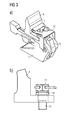
- Fig. 1 shows a view of the latch closure in the closed position.
- On a rail 1 is on one side of the rail foot Closure piece 2 by means of retaining clips 3, which hook under the rail at the other rail foot side attached.
- the adjusting tongue 4 of the switch is connected at its free end with a lock bearing 5.
- the adjusting tongue 4 is shown here in the adjacent position, ie the adjusting tongue 4 is pressed against the rail side.
- a closure pawl 6 is pivotally mounted in a bearing 7.
- a slide rod 8 is provided for the adjustment of the adjusting tongue 4, a slide rod 8 is provided. The slide rod 8 is moved transversely to the rail longitudinal axis by means of a drive, not shown.
- closure pawl 6 and the slide rod 8 are now designed such that the free end of the closure pawl 6 as in FIG. 1 shown under the foot of the rail 1 can slide through.
- This latch closure now causes the positioning tongue 4 to be positively connected via the locking pawl 6 to the rail 1 in the closed position.
- the setting of this connection can be achieved, for example, that the bearing 7 has an adjustment by means of eccentric.
- the orientation of the closure pawl 6 can be adjusted or readjusted such that a blocking surface 9 rests against the closure piece 2 with a defined clearance when the positioning tongue 4 bears against the flank of the rail 1.
- the lock stock 5 For mounting such a latch closure in a switch, inter alia, the lock stock 5 must be mounted at the foot of the adjusting tongue 4.
- the adjusting tongue 4 has a bore into which a locking screw 11 is screwed.
- the closure clip screw 11 is tightened according to the current state of the art with a maximum torque and then secured with a locking plate 12.
- the locking plate is designed as a spring plate and has a hole that corresponds to the screw head. It is first pushed over the hexagon head in the direction of the arrow and then snaps over the screw head when the screw head coincides with the hole in the locking plate 12.
- the hexagonal head of the locking clip screw 11 must be aligned with the locking plate 12, so that tightening the locking screw can be quite a re-tightening may be required by up to 60 °, which given the thread thickness of example M20 (and the associated thread pitches) again very much large forces required, which may possibly adversely affect the connected components.
- a first solution according to the invention for this task provides a closure bearing for a Weichenverstellan eleven with a foot of a Stellzunge penetrating locking bearing screw and a arranged between the foot and the screw head of the locking bearing screw spring assembly.
- the locking bearing screw with a relatively narrow definable Torque range are tightened and at the same time still has the rotational reserve to bring the position of the head of the locking bearing screw in accordance with a screw head depicting the hole in a locking plate, which then snaps when pushing over the head of the locking bearing screw as previously known.
- a second solution according to the invention for this purpose provides a closure bearing for a Weichenverstellan extract with a foot of a Stellzunge penetrating locking bearing screw and the head of the locking bearing screw annularly frictionally surrounding anti-rotation ring with an external toothing and adapted to this external toothing locking plate.
- the locking bearing screw it is also possible here to attract the locking bearing screw within a relatively small torque range and thereby align the locking bearing screw only in the Rast réellesmass the external teeth. If, for example, the outer toothing has a tooth number of 36 teeth, then the locking bearing screw must only be aligned within a range of a maximum of 10 °.
- the anti-rotation ring acts like an adapter for the Zahnungsmass and thus contributes to the fact that on the remaining construction of the lock bearing and the lock bearing screw no changes must be made, which is also absolutely beneficial for safety and approval considerations.
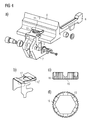
- FIG. 2 shows a schematic view of the adjusting tongue 4 with the lock bearing 7 fixed thereto in one opposite FIG. 1 enlarged view.
- the head 13 of the closure bearing screw 11 sets the closure bearing 7 with vertical pressure on the positioning tongue 4.
- the head 13 has a hexagon.
- the designed as a spring plate locking plate 12 has a hole that corresponds to the hexagon surface area. If the locking plate 12 is now pushed over the head 13, it bends upwards and locks in the moment above the head 13 when the hole and the head 13 are in complete agreement. Therefore, the head 13 must be aligned exactly with the hole in the locking plate 12.
- FIG. 3a now shows the situation according to FIG. 2 with a spring package 14 inserted according to the invention under the head 13 of the closure bearing screw 11 (detail view cf. FIG. 3b ).
- the lock bearing screw 11 can be set within a small torque range.
- this solution allows for a further slight tightening of the locking bearing screw 11 in order to bring the position of the screw head 13 into conformity with the hole in the locking plate 12.
- the spring reserve present in the spring assembly 14 ensures that the screw connection does not cause any unacceptable stresses in the screwed components.
- FIG. 4 shows the situation according to FIG. 2
- the anti-rotation adapter 15 has a ring-shaped design (compare Figure parts 4c and 4d) and has in its inner circumference a largely positive, but in each case non-positive course exactly to the course of the hexagonal head thirteenth the closure bearing screw 11 (see Figure 4d part).
- the anti-rotation adapter 15 On its outer circumference, the anti-rotation adapter 15 has an outer toothing 16, which is much finer than the hexagon of the head 13.
- a hole 17 in the locking plate 12 ' forms the course of the external teeth 16 exactly, so that the locking plate 12' engages over the anti-rotation adapter 15, if External teeth 16 and the hole 17 are in agreement.
- the locking bearing screw 11 or its head 13 need not be aligned during tightening. Smaller corrections of the screw position are possible by means of an insertable into the screw head 13 pin, which allow the fine adjustment of the locking bearing screw 11 relative to the contours of the hole 17 in the locking plate 12 '.
Landscapes
- Engineering & Computer Science (AREA)
- Mechanical Engineering (AREA)
- Seats For Vehicles (AREA)
- Connection Of Plates (AREA)
- Mechanical Control Devices (AREA)
Abstract
Description
Die vorliegende Erfindung bezieht sich auf einen Klinkenverschluss mit einer Verschlussklammerschraube.The present invention relates to a latch closure with a locking clip screw.
Zur Verstellung von Eisenbahnweichen werden unter anderem auch Klinkenverschlüsse eingesetzt. Der Aufbau eines Klinkenverschlusses ist in der europäischen Patentanmeldung
Derartige Verschlusslager werden in Eisenbahnweichen eingesetzt, um die Stellzungenspitzen an die benachbarte Schienenflanke heranzuziehen und daran festzuhalten. Die Stellzungen sind dabei über eine bestimmte Länge gleitbar auf den Schienenschwellen geführt. Das eine Ende geht dabei in fest mit den Schwellen verbundene Schienenstücke über, während die Zungenspitze mittels einer Vorrichtung verschiebbar ist. In Schliesslage wird dabei die Zungenspitze an die benachbarte Schienenflanke herangezogen und daran gehalten resp. geklammert, während es in der offenen Stellung mit einem bestimmten Abstand von der Schienenflanke positioniert wird. Bei dem dort offenbarten Klinkenverschluss liegt das Verschlusslager in geschlossener Stellung der Verschlussklinke formschlüssig am Verschlussstück anliegt. Damit wird verhindert, dass sich das Verschlusslager verdrehen kann. Damit wird auch verhindert, dass sich mit dieser Verdrehung die Stellzunge verdreht und von der Schienenflanke abgehoben wird resp. dass es zu einer Klaffung zwischen Schienenflanke und Zungenspitze kommt.
Bei solchen Sperrklinken kann nun das Problem auftreten, dass sich die Stellzunge 4 axial verdrehen kann. Dieses Verdrehen führt zu einem Abheben resp. Klaffen des oberen Bereiches der Stellzunge 4 von der Flanke der Schiene 1. Schon ein Abheben resp. Klaffen der Stellzunge um wenige Millimeter kann ungewünschte Folgen haben, indem dadurch die Räder eines Zuges an dieser Stelle anstossen können. Um dieses Problem zu lösen, ist am Fuss des Verschlusslagers 5 ein Steg 9 vorgesehen sein, welcher in geschlossener Stellung der Sperrklinke mit dem Fuss des Verschlussstückes 2 in Anschlag gelangt, wie in
Zur Montage eines derartigen Klinkenverschlusses in einer Weiche muss unter anderem das Verschlusslager 5 am Fuss der Stellzunge 4 montiert werden. Hierzu weist die Stellzunge 4 eine Bohrung auf, in die eine Verschlussklammerschraube 11 eingeschraubt wird. Dabei wird die Verschlussklammerschraube 11 gemäss dem heutigen Stand der Technik mit einem maximalen Drehmoment angezogen und anschliessend mit einem Sicherungsblech 12 gesichert. Das Sicherungsblech ist dabei als Federblech ausgestaltet und weist ein Loch auf, dass dem Schraubenkopf entspricht. Es wird dabei in Pfeilrichtung zunächst über den Sechskantkopf geschoben und rastet dann über dem Schraubenkopf ein, wenn der Schraubenkopf mit dem Loch im Sicherungsblech 12 übereinstimmt. Damit muss der Sechskantkopf der Verschlussklammerschraube 11 zu dem Sicherungsblech 12 ausgerichtet werden, so dass beim Festziehen der Verschlussklammerschraube durchaus ein nochmaliges Nachziehen um bis zu 60° erforderlich sein kann, was angesichts der Gewindestärken von beispielsweise M20 (und der damit verbundenen Gewindesteigungen) noch einmal sehr grosse Kräfte erforderlich macht, die möglicherweise ungünstig auf die verbundenen Bauteile wirken können.For mounting such a latch closure in a switch, inter alia, the
Es ist daher die Aufgabe der vorliegenden Erfindung eine Lösung für die Befestigung des Verschlusslagers am Fuss der Stellzunge anzugeben, welche sich durch eine vereinfachte und die Bauteile weniger belastende Montage auszeichnet.It is therefore the object of the present invention to provide a solution for the attachment of the closure bearing at the foot of the positioning tongue, which is characterized by a simplified and less stressful assembly components.
Eine erste erfindungsgemässe Lösung für diese Aufgabe sieht ein Verschlusslager für eine Weichenverstellanordnung mit einer einen Fuss einer Stellzunge durchdringenden Verschlusslagerschraube und einem zwischen dem Fuss und dem Schraubenkopf der Verschlusslagerschraube angeordneten Federpaket vor. Auf diese Weise kann die Verschlusslagerschraube mit einem relativ schmal definierbaren Drehmomentbereich angezogen werden und hat dabei gleichzeitig noch die Drehreserve, um die Position des Kopfes der Verschlusslagerschraube in Übereinstimmung mit einem den Schraubenkopf abbildenden Loch in einem Sicherungsblech zu bringen, dass dann beim Einschieben wie bisher bekannt über den Kopf der Verschlusslagerschraube einrastet.A first solution according to the invention for this task provides a closure bearing for a Weichenverstellanordnung with a foot of a Stellzunge penetrating locking bearing screw and a arranged between the foot and the screw head of the locking bearing screw spring assembly. In this way, the locking bearing screw with a relatively narrow definable Torque range are tightened and at the same time still has the rotational reserve to bring the position of the head of the locking bearing screw in accordance with a screw head depicting the hole in a locking plate, which then snaps when pushing over the head of the locking bearing screw as previously known.
Eine zweite erfindungsgemässe Lösung für diese Aufgabe sieht ein Verschlusslager für eine Weichenverstellanordnung mit einer einen Fuss einer Stellzunge durchdringenden Verschlusslagerschraube und einen den Kopf der Verschlusslagerschraube ringförmig kraftschlüssig umgebenden Drehsicherungsring mit einer Aussenverzahnung sowie ein an diese Aussenverzahnung angepasstes Sicherungsblech vor. Damit ist es hier ebenfalls möglich, die Verschlusslagerschraube innerhalb eines relativ kleinen Drehmomentbereichs anzuziehen und dabei die Verschlusslagerschraube nur in dem Rasterungsmass der Aussenverzahnung ausrichten zu müssen. Hat also beispielsweise die Aussenverzahnung eine Zahnzahl von 36 Zähnen, so muss die Verschlusslagerschraube nur innerhalb eines Bereichs von maximal 10° ausgerichtet werden. Der Drehsicherungsring wirkt dabei wie ein Adapter für das Zahnungsmass und trägt so dazu bei, dass an der übrigen Konstruktion des Verschlusslager und der Verschlusslagerschraube keine Veränderungen vorgenommen werden müssen, was auch sicherheits- und Genehmigungserwägungen absolut vorteilhaft ist.A second solution according to the invention for this purpose provides a closure bearing for a Weichenverstellanordnung with a foot of a Stellzunge penetrating locking bearing screw and the head of the locking bearing screw annularly frictionally surrounding anti-rotation ring with an external toothing and adapted to this external toothing locking plate. Thus, it is also possible here to attract the locking bearing screw within a relatively small torque range and thereby align the locking bearing screw only in the Rasterungsmass the external teeth. If, for example, the outer toothing has a tooth number of 36 teeth, then the locking bearing screw must only be aligned within a range of a maximum of 10 °. The anti-rotation ring acts like an adapter for the Zahnungsmass and thus contributes to the fact that on the remaining construction of the lock bearing and the lock bearing screw no changes must be made, which is also absolutely beneficial for safety and approval considerations.
Bevorzugte Ausführungsbeispiele werden nachfolgend anhand einer Zeichnung näher erläutert. Dabei zeigen:
Figur 1- eine schematische Seitenansicht eines im Einsatz befindlichen Klinkenverschlusses mit einem an einer Stockschiene verspannten Verschlussstück und einem an einer Stellzunge festgesetzten Verschlusslager gemäss dem Stand der Technik;
Figur 2- eine vergrösserte Ansicht der Stellzunge mit daran festgesetztem Verschlusslager gemäss dem Stand der Technik;
- Figur 3
- eine schematische Ansicht eines Verschlusslagers mit eingelegtem Federpaket; und
Figur 4- eine schematische Ansicht eines Verschlusslagers mit auf die Verschlussklammerschraube ausgesetzten Drehsicherungs-Adapter.
- FIG. 1
- a schematic side view of a pawl closure in use with a braced on a pole rail closure piece and a fixed to a positioning tab lock bearing according to the prior art;
- FIG. 2
- an enlarged view of the positioning tongue with it fixed lock stock according to the prior art;
- FIG. 3
- a schematic view of a closure bearing with inserted spring package; and
- FIG. 4
- a schematic view of a closure bearing exposed to the locking screw screw anti-rotation adapter.
Claims (1)
Priority Applications (1)
| Application Number | Priority Date | Filing Date | Title |
|---|---|---|---|
| EP11179473.1A EP2479080A3 (en) | 2011-01-19 | 2011-08-31 | Clamp lock with lock clamp screw |
Applications Claiming Priority (2)
| Application Number | Priority Date | Filing Date | Title |
|---|---|---|---|
| EP11151347 | 2011-01-19 | ||
| EP11179473.1A EP2479080A3 (en) | 2011-01-19 | 2011-08-31 | Clamp lock with lock clamp screw |
Publications (2)
| Publication Number | Publication Date |
|---|---|
| EP2479080A2 true EP2479080A2 (en) | 2012-07-25 |
| EP2479080A3 EP2479080A3 (en) | 2015-10-28 |
Family
ID=44509072
Family Applications (1)
| Application Number | Title | Priority Date | Filing Date |
|---|---|---|---|
| EP11179473.1A Ceased EP2479080A3 (en) | 2011-01-19 | 2011-08-31 | Clamp lock with lock clamp screw |
Country Status (3)
| Country | Link |
|---|---|
| US (1) | US8870127B2 (en) |
| EP (1) | EP2479080A3 (en) |
| CN (1) | CN102602428B (en) |
Cited By (1)
| Publication number | Priority date | Publication date | Assignee | Title |
|---|---|---|---|---|
| EP2703249A1 (en) * | 2012-09-03 | 2014-03-05 | Siemens Schweiz AG | Pawl lock with adjustable lock bearing |
Families Citing this family (2)
| Publication number | Priority date | Publication date | Assignee | Title |
|---|---|---|---|---|
| NL2006119C2 (en) * | 2011-02-02 | 2012-08-06 | Spot Safety Professionals On Track | CLAMP MECHANISM FOR LOCKING AT LEAST AN OBJECT TO A RAIL AND A COMPOSITION. |
| CN112458801A (en) * | 2020-11-30 | 2021-03-09 | 张翔 | Switch rail displacement compensation device |
Citations (1)
| Publication number | Priority date | Publication date | Assignee | Title |
|---|---|---|---|---|
| EP0624508A1 (en) | 1993-05-10 | 1994-11-17 | Siemens Integra Verkehrstechnik Ag | Clamp lock for railway switches |
Family Cites Families (7)
| Publication number | Priority date | Publication date | Assignee | Title |
|---|---|---|---|---|
| DE1530373B1 (en) * | 1963-04-22 | 1970-05-14 | Peddinghaus Carl Dan Kg | Lock box attachment for the clip tips |
| CN87202869U (en) * | 1987-03-10 | 1987-10-21 | 铁道部科学研究院铁道建筑研究所 | Jointing bolt-locking device for rail joint |
| DE8707708U1 (en) * | 1987-05-29 | 1987-08-27 | Metacon AG, Zürich | Device for attaching a submersible spout |
| AT390084B (en) * | 1988-05-20 | 1990-03-12 | Voest Alpine Maschinenbau | SOFT WITH A HEART PIECE WITH A MOVABLE MAIN AND EXTRA TIP |
| US5501418A (en) * | 1994-10-03 | 1996-03-26 | Humphrey; John | Switch point roller assist apparatus |
| DE19502105C5 (en) * | 1995-01-24 | 2004-12-30 | Carl Dan. Peddinghaus Gmbh & Co Kg | Locking device for switch tongues |
| US6732980B2 (en) * | 2002-10-08 | 2004-05-11 | Progress Rail Services Corp. | Railway frog wear component |
-
2011
- 2011-08-31 EP EP11179473.1A patent/EP2479080A3/en not_active Ceased
-
2012
- 2012-01-18 US US13/352,396 patent/US8870127B2/en not_active Expired - Fee Related
- 2012-01-18 CN CN201210015124.8A patent/CN102602428B/en active Active
Patent Citations (1)
| Publication number | Priority date | Publication date | Assignee | Title |
|---|---|---|---|---|
| EP0624508A1 (en) | 1993-05-10 | 1994-11-17 | Siemens Integra Verkehrstechnik Ag | Clamp lock for railway switches |
Cited By (1)
| Publication number | Priority date | Publication date | Assignee | Title |
|---|---|---|---|---|
| EP2703249A1 (en) * | 2012-09-03 | 2014-03-05 | Siemens Schweiz AG | Pawl lock with adjustable lock bearing |
Also Published As
| Publication number | Publication date |
|---|---|
| US8870127B2 (en) | 2014-10-28 |
| EP2479080A3 (en) | 2015-10-28 |
| CN102602428A (en) | 2012-07-25 |
| CN102602428B (en) | 2016-12-07 |
| US20120181393A1 (en) | 2012-07-19 |
Similar Documents
| Publication | Publication Date | Title |
|---|---|---|
| EP3717786B1 (en) | Tolerance compensation arrangement with safety clamp | |
| DE69006170T2 (en) | Screw dowels, especially for soft material, and suitable tools. | |
| EP0400224A2 (en) | Endosseous implant and tool | |
| WO2006042750A1 (en) | Traction-pressure rod | |
| DE9409123U1 (en) | Device for stabilizing or compressing or distracting sections of the spine | |
| EP2032864B1 (en) | Washer and threaded assembly provided therewith | |
| EP3586018B1 (en) | Fastening device and fastening assembly | |
| EP3032093B1 (en) | Fastening device for fastening a rotor blade to a rotor hub of a wind energy plant | |
| DE3404118A1 (en) | METHOD AND DEVICE FOR ATTACHING A NUT TO A PLATE-SHAPED WORKPIECE | |
| EP0905389A2 (en) | Screw for anchoring in concrete | |
| EP2479080A2 (en) | Clamp lock with lock clamp screw | |
| EP2816243A1 (en) | Fastening element | |
| EP2479081B1 (en) | Clamp lock with lock clamp screw | |
| DE102020205995B3 (en) | Tolerance compensation device | |
| DE102009037820C5 (en) | Arrangement for connecting wooden components | |
| DE29805045U1 (en) | Plastic nut | |
| DE102009056144B4 (en) | Device for connecting components | |
| EP3565776B1 (en) | Container transport system with a replaceable track element | |
| EP3412246B1 (en) | Holder for abutment blank for tooth implants | |
| WO2018134109A1 (en) | Fastening arrangement and washer | |
| DE3410868A1 (en) | Re-usable, positively-locking nut lock | |
| DE102010032895A1 (en) | Anchoring system for fastening parts at rock, stone and concrete, has anchor rod, cylindrical retaining element provided with transverse break-through, and flexible securing element cooperating with anchor rod and made of plastic i.e. nylon | |
| EP4159937B1 (en) | Device for fixing a sanitary fitting | |
| EP1028259A2 (en) | Device for detachably anchoring a fire resistant member to a metal member | |
| EP0020916B1 (en) | Affixation device |
Legal Events
| Date | Code | Title | Description |
|---|---|---|---|
| PUAI | Public reference made under article 153(3) epc to a published international application that has entered the european phase |
Free format text: ORIGINAL CODE: 0009012 |
|
| AK | Designated contracting states |
Kind code of ref document: A2 Designated state(s): AL AT BE BG CH CY CZ DE DK EE ES FI FR GB GR HR HU IE IS IT LI LT LU LV MC MK MT NL NO PL PT RO RS SE SI SK SM TR |
|
| AX | Request for extension of the european patent |
Extension state: BA ME |
|
| PUAL | Search report despatched |
Free format text: ORIGINAL CODE: 0009013 |
|
| AK | Designated contracting states |
Kind code of ref document: A3 Designated state(s): AL AT BE BG CH CY CZ DE DK EE ES FI FR GB GR HR HU IE IS IT LI LT LU LV MC MK MT NL NO PL PT RO RS SE SI SK SM TR |
|
| AX | Request for extension of the european patent |
Extension state: BA ME |
|
| RIC1 | Information provided on ipc code assigned before grant |
Ipc: B61L 5/10 20060101AFI20150918BHEP |
|
| 17P | Request for examination filed |
Effective date: 20160304 |
|
| RBV | Designated contracting states (corrected) |
Designated state(s): AL AT BE BG CH CY CZ DE DK EE ES FI FR GB GR HR HU IE IS IT LI LT LU LV MC MK MT NL NO PL PT RO RS SE SI SK SM TR |
|
| STAA | Information on the status of an ep patent application or granted ep patent |
Free format text: STATUS: EXAMINATION IS IN PROGRESS |
|
| 17Q | First examination report despatched |
Effective date: 20170322 |
|
| STAA | Information on the status of an ep patent application or granted ep patent |
Free format text: STATUS: THE APPLICATION HAS BEEN REFUSED |
|
| 18R | Application refused |
Effective date: 20180129 |