EP2327612A1 - Fahrzeug zur selbständigen Inspektion von schwer zugänglichen Innenräumen - Google Patents
Fahrzeug zur selbständigen Inspektion von schwer zugänglichen Innenräumen Download PDFInfo
- Publication number
- EP2327612A1 EP2327612A1 EP10190900A EP10190900A EP2327612A1 EP 2327612 A1 EP2327612 A1 EP 2327612A1 EP 10190900 A EP10190900 A EP 10190900A EP 10190900 A EP10190900 A EP 10190900A EP 2327612 A1 EP2327612 A1 EP 2327612A1
- Authority
- EP
- European Patent Office
- Prior art keywords
- vehicle
- wheels
- vehicle according
- permanent magnets
- sensor
- Prior art date
- Legal status (The legal status is an assumption and is not a legal conclusion. Google has not performed a legal analysis and makes no representation as to the accuracy of the status listed.)
- Granted
Links
Images


Classifications
-
- B—PERFORMING OPERATIONS; TRANSPORTING
- B62—LAND VEHICLES FOR TRAVELLING OTHERWISE THAN ON RAILS
- B62D—MOTOR VEHICLES; TRAILERS
- B62D57/00—Vehicles characterised by having other propulsion or other ground- engaging means than wheels or endless track, alone or in addition to wheels or endless track
- B62D57/02—Vehicles characterised by having other propulsion or other ground- engaging means than wheels or endless track, alone or in addition to wheels or endless track with ground-engaging propulsion means, e.g. walking members
- B62D57/024—Vehicles characterised by having other propulsion or other ground- engaging means than wheels or endless track, alone or in addition to wheels or endless track with ground-engaging propulsion means, e.g. walking members specially adapted for moving on inclined or vertical surfaces
-
- G—PHYSICS
- G01—MEASURING; TESTING
- G01M—TESTING STATIC OR DYNAMIC BALANCE OF MACHINES OR STRUCTURES; TESTING OF STRUCTURES OR APPARATUS, NOT OTHERWISE PROVIDED FOR
- G01M11/00—Testing of optical apparatus; Testing structures by optical methods not otherwise provided for
- G01M11/08—Testing mechanical properties
-
- G—PHYSICS
- G01—MEASURING; TESTING
- G01M—TESTING STATIC OR DYNAMIC BALANCE OF MACHINES OR STRUCTURES; TESTING OF STRUCTURES OR APPARATUS, NOT OTHERWISE PROVIDED FOR
- G01M5/00—Investigating the elasticity of structures, e.g. deflection of bridges or air-craft wings
- G01M5/0033—Investigating the elasticity of structures, e.g. deflection of bridges or air-craft wings by determining damage, crack or wear
-
- G—PHYSICS
- G01—MEASURING; TESTING
- G01M—TESTING STATIC OR DYNAMIC BALANCE OF MACHINES OR STRUCTURES; TESTING OF STRUCTURES OR APPARATUS, NOT OTHERWISE PROVIDED FOR
- G01M5/00—Investigating the elasticity of structures, e.g. deflection of bridges or air-craft wings
- G01M5/0075—Investigating the elasticity of structures, e.g. deflection of bridges or air-craft wings by means of external apparatus, e.g. test benches or portable test systems
-
- G—PHYSICS
- G01—MEASURING; TESTING
- G01M—TESTING STATIC OR DYNAMIC BALANCE OF MACHINES OR STRUCTURES; TESTING OF STRUCTURES OR APPARATUS, NOT OTHERWISE PROVIDED FOR
- G01M5/00—Investigating the elasticity of structures, e.g. deflection of bridges or air-craft wings
- G01M5/0091—Investigating the elasticity of structures, e.g. deflection of bridges or air-craft wings by using electromagnetic excitation or detection
-
- G—PHYSICS
- G01—MEASURING; TESTING
- G01N—INVESTIGATING OR ANALYSING MATERIALS BY DETERMINING THEIR CHEMICAL OR PHYSICAL PROPERTIES
- G01N35/00—Automatic analysis not limited to methods or materials provided for in any single one of groups G01N1/00 - G01N33/00; Handling materials therefor
- G01N35/02—Automatic analysis not limited to methods or materials provided for in any single one of groups G01N1/00 - G01N33/00; Handling materials therefor using a plurality of sample containers moved by a conveyor system past one or more treatment or analysis stations
- G01N35/04—Details of the conveyor system
- G01N2035/0474—Details of actuating means for conveyors or pipettes
- G01N2035/0489—Self-propelled units
Definitions
- the present invention relates to the field of inspection of components with difficult to access interior spaces. It relates to a vehicle for independent inspection of difficult to access interior spaces according to the preamble of claim 1.
- the object is solved by the entirety of the features of claim 1.
- the invention proposes a vehicle which comprises at least two wheels which are rotatable about a common axis and spaced apart from each other in the axial direction, and which comprise adhesive means, in particular magnetic means, which hold the vehicle against the gravitational force with the wheels against the respective inner wall ,
- the uniaxial construction makes it possible to introduce the vehicle in the axial direction through limited openings in the interior to be inspected. In the interior it may be due to the two driven wheels in any Be maneuvered and moved, wherein it is held on vertical walls or in the overhead mode by adhesive, preferably magnetic forces, in contact with the respective wall.
- the DE-U1-298 08 730 discloses a mobile device with two wheels and a wheel axle and a pendulum mounted on the wheel axle device body, which may be, for example, a vehicle cabin.
- the wheels are driven by an electric or combustion engine via a central differential gear and two differentials assigned to the wheels.
- WO-A1-01 / 28797 is a single-axle vehicle with two independently driven wheels known (see, for example, the local Fig. 1 ), in which the steering is effected by different rotational speed of the wheels and provides a low center of gravity for the movement of the vehicle.
- Recon Scout ® a single-axis, two-wheeled, miniaturized mobile robot is known, which can remotely record in a hostile or dangerous environment with a built-in video camera and transmit images to a receiver.
- the rugged robot has plastic wheels sandwiched between a cylindrical titanium housing housing the camera, drive and control. On the outside of the housing is a flexible Stabilizing tail attached, which prevents a rotation of the housing when driving forward.
- Such a robot has an exemplary wheel diameter of about 8 cm, a length in the axial direction of about 19 cm and a weight of about 0.5 kg.
- the inventive vehicle is characterized by the fact that it contains adhesive, in particular magnetic means with which it can also hold on vertical or upside-down walls of ferromagnetic material so that its wheels make contact with the wall not lose. It goes without saying that the adhesive or magnetic means must be strong enough to keep the vehicle along with its built-in (optical or otherwise) inspection devices against gravity on an inner wall.
- an adhesive effect can be achieved by vacuum (suction) or adhesive.
- the adhesive or magnetic means comprise at least one permanent magnet.
- at least two permanent magnets are provided, which are assigned to the individual wheels.
- the permanent magnets can be arranged partially or completely in the wheels for protection against external influences. This results in addition to the advantage that the permanent magnets are placed exactly where the contact between the wheel and wall must be maintained, which has a favorable effect, especially on uneven walls. With appropriately designed permanent magnets, large adhesive forces can be achieved without having to provide energy in the vehicle.
- the permanent magnets are decoupled from the wheels of the vehicle.
- the decoupling ensures that the permanent magnets remain aligned with the wall when the wheels turn or (in one corner of a room) can align with another wall without the wheels having to move.
- each of the wheels is assigned a separate drive, and the drives are powered from a stored in the vehicle energy storage and controlled by a housed in the vehicle control. This makes it possible to achieve great mobility of the vehicle with little design effort.
- an energy storage is in particular a battery or an accumulator into consideration.
- the vehicle is controlled from outside via a control line and the inspection results are also transmitted to the outside via this line.
- the controller can receive control commands from the outside wirelessly. Accordingly, the inspection results are then wirelessly transmitted to the outside or stored in the vehicle for later evaluation.
- An improved adaptation of the vehicle to an uneven surface can, according to a further embodiment, be achieved in that the at least two wheels are connected to one another by an elastically flexible cross member acting as suspension.
- a extending between the wheels in the axial direction preferably cylindrical housing.
- At least one sensor from the series camera, optical sensor, electrical sensor, electromagnetic sensor, ultrasonic sensor or the like is arranged on the vehicle.
- a video camera can be used (with appropriate illumination by a light source carried) for the optical detection of the wall condition, but also for the detection of the route.
- Other sensors that work with ultrasound or eddy currents, for example, can be used for crack detection or nondestructive material testing.
- Fig. 1 is shown in a side view perpendicular to the axis of an inspection vehicle according to an embodiment of the invention.
- the vehicle 10 is formed as a uniaxial vehicle and has two wheels 12 and 13 which are rotatably mounted about a common axis 14 and spaced along the axis 14 from each other.
- the wheels 12, 13 are preferably made of a material, such as a plastic, which does not develop a magnetic shielding effect. The material may be chosen so that the wheels on the designated background, an inner wall 24 of a cast body, have a sufficient grip.
- the outer circumference of the wheels 12, 13 may also be provided with a corresponding coating or elements such as transverse ribs, which cause an improved grip.
- the housing 11 is preferably cylindrical in order to slide easily in use on bumps. So that the vehicle 10 rests with its wheels in any position on the existing of ferromagnetic material inner wall 24, two strong permanent magnets 21, 22 are respectively disposed in the immediate vicinity of one of the wheels 12, 13 on the underside of the housing. This arrangement of the permanent magnets 21, 22 ensures that the housing 11 always remains stable in the same orientation to the inner wall 24, even if the wheels 12, 13 rotate forward or backward.
- Each of the two wheels 12, 13 is driven via its own drive shaft 17 or 18 by its own drive 15 or 16, which comprises an electric motor and is supplied with energy from an energy store 20.
- the wheels 12, 13 independently perform any rotational movements and thus steer the vehicle in the desired direction or rotate on the spot.
- the wheels 15, 16 are then decoupled from each other by appropriate differential devices.
- Each wheel 12, 13 together with the drive shaft 17, 18 and the drive 15, 16 a unit. If the two units or drives mechanically connected by an elastically flexible cross member 30, which is then anchored to the housing, results for the vehicle 10, a suspension that improves the handling.
- the drives 15, 16 and thus the direction of movement and speed of the vehicle 10 are controlled by a controller 19, which wirelessly receives commands from a remote control device 31 and possibly sends inspection results to the outside.
- the controller 19 may cooperate with on-vehicle attitude and acceleration sensors to keep the vehicle 10 in balance.
- permanent magnets 25, 26 are provided in the wheels 12, 13.
- the permanent magnets 25, 26 on the one hand against external influences (bumps, dust, magnetizable particles, etc.) protected.
- the attractive magnetic forces are concentrated exactly where the grip of the wheels 12, 13 attaches to the inner wall 24.
- the permanent magnets 25, 26 may, for example, in Fig. 2 have shown, semicircle-like edge contour.
- FIG. 1 shown construction of the vehicle 10 causes the vehicle to drive in an interior without problems along room corners and rise on vertical walls or can move overhead on ceilings, as is apparent from Fig. 3 becomes clear:
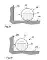
- Fig. 3 a corner of the room is shown at the two inner walls 24a, b of an interior to be inspected collide at right angles.
- the vehicle 10 on the horizontal Inner wall 24a driving (the wheels rotate counterclockwise) to the vertical inner wall 24b moves to ( Fig. 3a, Fig.
- the permanent magnet 25 arranged asymmetrically with respect to the axis 14 in the front wheel 12 (as well as the invisible permanent magnet 26 in the rear wheel 13) points downwards and develops the maximum attractive force vertically below the axis (double arrow in FIG Fig. 3a, b ) with respect to the underlying inner wall 24a.
- the permanent magnet 25 is directed increasingly in equal parts on the horizontal and vertical inner wall 24a and 24b, so that the vehicle 10 with its wheels 12, 13 bears against both walls simultaneously. Turning the wheels 12, 13 then further counterclockwise, the vehicle 10 moves vertically upwards on the vertical inner wall 24b, wherein the permanent magnet 25 aligns with increasing distance from the horizontal inner wall 24a exclusively on the vertical inner wall 24b.
- the housing 11 When the permanent magnets 21, 22 and 25, 26 are fixedly connected to the housing 11, the housing 11 has a corresponding orientation to the respective inner wall, on the surface of which the vehicle 10 moves.
- sensors 23 (cameras, crack detectors, etc .; Fig. 1 ) attached to the housing 11, these are oriented in the same way to the wall surface. If the permanent magnets, however, mounted freely pivotable about the axis 14, the housing 11 can be brought with the attached sensors 23 by a corresponding position control with position sensors in an arbitrarily adjustable position.
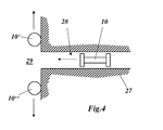
- Fig. 4 schematically shows the insertion of the vehicle 10 from Fig. 1
- the vehicle 10 can be inserted in the axial orientation through a narrow bore 28 in the interior of a steam box 27 or the like., Then - like the other vehicles 10 'and 10 "- along the inner wall of the extended interior 29 for inspection purposes to drive. From this it is also clear that the inspection of a larger structure can be handled faster if several vehicles of the type described are used simultaneously for inspection. Furthermore, it is conceivable to mechanically couple a plurality of vehicles of the type described to a movable, larger assembly.
Landscapes
- Physics & Mathematics (AREA)
- Engineering & Computer Science (AREA)
- General Physics & Mathematics (AREA)
- Aviation & Aerospace Engineering (AREA)
- Chemical & Material Sciences (AREA)
- Combustion & Propulsion (AREA)
- Electromagnetism (AREA)
- Transportation (AREA)
- Mechanical Engineering (AREA)
- Analytical Chemistry (AREA)
- Investigating Or Analyzing Materials By The Use Of Ultrasonic Waves (AREA)
- Investigating Or Analyzing Materials By The Use Of Magnetic Means (AREA)
- Control Of Position, Course, Altitude, Or Attitude Of Moving Bodies (AREA)
Abstract
Description
- Die vorliegende Erfindung bezieht sich auf das Gebiet der Inspektion von Bauteilen mit schwer zugänglichen Innenräumen. Sie betrifft ein Fahrzeug zur selbständigen Inspektion von schwer zugänglichen Innenräumen gemäss dem Oberbegriff des Anspruchs 1.
- Die Inspektion von grossen Anlagen zur Energieerzeugung wie beispielsweise Gas- oder Dampfturbinen sind von grossem Interesse, um rechtzeitig Schäden zu entdecken und die Ausfallzeit derartiger Anlagen zu minimieren.
- Besonders grosse Gussteile dieser Anlagen wie z.B. Dampfkästen, d.h. die Strukturen, welche die Frischdampfzuleitungen mit der Dampfturbine verbinden und alle notwendigen Ventile enthalten (siehe z.B. die
EP-A1-0 005 616 oder dieUS-A-4,592,699 ), zeigen häufig Rissbildung, weil sie hohen Drücken und Temperaturen ausgesetzt sind. Wenn eine solche Rissbildung rechtzeitig, also in einem frühen Stadium, entdeckt wird, können geeignete Massnahmen eingeleitet und so schwerwiegende Folgen vermieden werden. - Während eine Inspektion auf der Aussenseite derartiger Strukturen vergleichsweise einfach ist, wird die Inspektion der Innenwände dadurch erschwert, dass die Zugangsöffnungen zu den Innenräumen im Vergleich zu den Innenräumen selbst oft sehr schmal sind und die Innenwände unregelmässige, insbesondere konkave, Formen aufweisen, die den Platz für eine in den Innenraum eingeführte Inspektionsvorrichtung begrenzen.
- Es ist daher Aufgabe der Erfindung, eine Vorrichtung zu schaffen, welche mit Vorteil für die Inspektion von Innenräumen bzw. Innenwänden in derartigen Strukturen einsetzbar ist, sich durch geringen Platzbedarf und eine gute Manövrierfähigkeit auszeichnet, für eine Vielzahl von Inspektionsarten geeignet ist und ohne Probleme an Innenwänden beliebiger räumlicher Orientierung entlang bewegt werden kann.
- Die Aufgabe wird durch die Gesamtheit der Merkmale des Anspruchs 1 gelöst. Die Erfindung schlägt ein Fahrzeug vor, welches wenigstens zwei um eine gemeinsame Achse drehbare, in axialer Richtung voneinander beabstandete, unabhängig voneinander antreibbare Räder umfasst und Haftmittel, insbesondere magnetische Mittel, aufweist, welche das Fahrzeug entgegen der Schwerkraft mit den Rädern an der jeweiligen Innenwand halten.
- Der einachsige Aufbau ermöglicht es, das Fahrzeug in Achsenrichtung durch begrenzte Öffnungen in den zu inspizierenden Innenraum einzuführen. Im Innenraum kann es aufgrund der beiden angetriebenen Räder in beliebige Richtung manövriert und verfahren werden, wobei es an vertikalen Wänden oder im Über-Kopf-Modus durch Haftmittel, vorzugsweise magnetische Kräfte, in Kontakt mit der jeweiligen Wand gehalten wird.
- Einachsige Fahrzeuge mit zwei separat angetriebenen Rädern sind für sich genommen seit Längerem bekannt. Die
DE-U1-298 08 730 offenbart ein fahrbares Gerät mit zwei Rädern und einer Radachse und einem an der Radachse pendelnd gelagerten Geräte-Grundkörper, der beispielsweise eine Fahrzeugkabine sein kann. Der Antrieb der Räder erfolgt durch einen Elektro- oder Verbrennungsmotor über ein zentrales Differentialgetriebe und zwei den Rädern zugeordnete Differentiale. - Aus der
WO-A1-01 /28797 Fig. 1 ), bei welchem die Lenkung durch unterschiedliche Drehgeschwindigkeit der Räder bewirkt wird und ein tiefliegender Schwerpunkt für die Fortbewegung des Fahrzeugs sorgt. - Aus der
US-B1-7,056,185 ist ein ferngesteuertes einachsiges Geländefahrzeug bekannt, dass mit in allen Richtungen wirksamen Rädern ausgestattet ist und daher ein sehr aufwändige und anfällige Mechanik aufweist. - In der
US-A1-2008/0173493 ist ein zweirädriger Roboter beschrieben, wobei ausführlich auf die für den Betrieb notwendige Steuerung der angetriebenen Räder eingegangen wird. - Schliesslich ist unter dem Markennamen Recon Scout® ein einachsiger, zweirädriger, miniaturisierter mobiler Roboter bekannt, der ferngesteuert in einer feindlichen oder gefährlichen Umgebung mit einer eingebauten Videokamera Bilder aufnehmen und an einen Empfänger übermitteln kann. Der robust ausgeführte Roboter hat Kunststoffräder, zwischen denen ein zylindrisches Gehäuse aus Titan angeordnet ist, in welchen die Kamera, der Antrieb und die Steuerung untergebracht sind. Am Gehäuse ist aussen ein flexibler Stabilisierungsschwanz ("stabilizing tail") angebracht, der eine Rotation des Gehäuses beim Vorwärtsfahren verhindert. Ein solcher Roboter hat einen beispielhaften Raddurchmesser von etwa 8 cm, eine Länge in axialer Richtung von etwa 19 cm und ein Gewicht von etwa 0,5 kg.
- Von diesen bekannten einachsigen, zweirädrigen Fahrzeugen setzt sich das erfindungsgemässe Fahrzeug dadurch ab, dass es Haftmittel, insbesondere magnetische Mittel enthält, mit denen es sich auch an vertikalen oder über Kopf stehenden Wänden aus ferromagnetischem Material so halten kann, dass seine Räder den Kontakt zur Wand nicht verlieren. Es versteht sich dabei von selbst, dass die Haftmittel bzw. magnetischen Mittel ausreichend stark sein müssen, um das Fahrzeug mitsamt seinen eingebauten (optischen oder anderweitigen) Inspektionseinrichtungen gegen die Schwerkraft über Kopf an einer Innenwand zu halten.
- Grundsätzlich könnet eine haftende Wirkung durch Unterdruck (Saugmittel) oder Klebemittel erreicht werden. Gemäss einer Ausgestaltung der Erfindung umfassen die Haftmittel bzw. magnetischen Mittel jedoch wenigstens einen Permanentmagneten. Vorzugsweise sind wenigstens zwei Permanentmagnete vorgesehen, die den einzelnen Rädern zugeordnet sind. Insbesondere können die Permanentmagnete zum Schutz vor äusseren Einwirkungen teilweise oder ganz in den Rädern angeordnet sein. Hierdurch ergibt sich zusätzlich der Vorteil, dass die Permanentmagnete genau dort platziert sind, wo der Kontakt zwischen Rad und Wand aufrechterhalten werden muss, was sich besonders bei unebenen Wänden günstig auswirkt. Mit entsprechend ausgelegten Permanentmagneten lassen sich grosse Haftkräfte erreichen, ohne dass in dem Fahrzeug dafür Energie bereitgestellt werden muss.
- Gemäss einer anderen Ausgestaltung sind die Permanentmagnete von den Rädern des Fahrzeugs entkoppelt. Die Entkopplung sorgt dafür, dass die Permanentmagnete auf die Wand ausgerichtet bleiben, wenn sich die Räder drehen, bzw. sich (in einer Raumecke) auf eine andere Wand ausrichten können, ohne dass sich die Räder bewegen müssen.
- Der unabhängige Antrieb der Räder kann grundsätzlich durch entsprechende Differentialanordnungen erreicht werden, wie dies in der eingangs genannten Druckschrift
DE-U1-298 08 730 beschrieben ist. Gemäss einer Ausgestaltung der Erfindung ist jedem der Räder jedoch ein eigener Antrieb zugeordnet, und die Antriebe werden aus einem im Fahrzeug untergebrachten Energiespeicher mit Energie versorgt und von einer im Fahrzeug untergebrachten Steuerung gesteuert. Hierdurch lässt sich mit geringem konstruktiven Aufwand eine grosse Beweglichkeit des Fahrzeugs erreichen. Als Energiespeicher kommt insbesondere eine Batterie oder ein Akkumulator in Betracht. - Es ist im Rahmen der Erfindung durchaus denkbar, dass das Fahrzeug über eine Steuerleitung von aussen gesteuert und die Inspektionsergebnisse über diese Leitung auch nach aussen übertragen werden. Um dem Fahrzeug jedoch eine uneingeschränkte Manövrierfähigkeit zu ermöglichen, ist es von Vorteil, wenn die Steuerung von aussen auf drahtlosem Wege Steuerbefehle empfangen kann. Entsprechend werden dann die Inspektionsergebnisse drahtlos nach aussen übertragen oder aber im Fahrzeug für eine spätere Auswertung abgespeichert.
- Eine verbesserte Anpassung des Fahrzeugs an einen unebenen Untergrund kann gemäss einer weiteren Ausgestaltung dadurch erreicht werden, dass die wenigstens zwei Räder durch einen als Federung wirkenden, elastisch biegsamen Querträger miteinander verbunden sind.
- Um die im Fahrzeug untergebrachten Einrichtungen wie Antrieb und Steuerung zu platzsparend zu schützen, weist das Fahrzeug gemäss einer anderen Ausgestaltung ein sich zwischen den Rädern in axialer Richtung erstreckendes, vorzugsweise zylindrisches Gehäuse auf.
- Zu Inspektions- und/oder Steuerungszwecken ist am Fahrzeug wenigstens ein Sensor aus der Reihe Kamera, optischer Sensor, elektrischer Sensor, elektromagnetischer Sensor, Ultraschallsensor, oder dgl., angeordnet. Eine Videokamera kann dabei (mit entsprechender Ausleuchtung durch eine mitgeführte Lichtquelle) zur optischen Erkennung der Wandbeschaffenheit, aber auch zur Erkennung des Fahrweges eingesetzt werden. Andere Sensoren, die beispielsweise mit Ultraschall oder Wirbelströmen arbeiten, können zur Risserkennung bzw. zerstörungsfreien Werkstoffprüfung eingesetzt werden.
- Die Erfindung soll nachfolgend anhand von Ausführungsbeispielen im Zusammenhang mit der Zeichnung näher erläutert werden. Es zeigen
- Fig. 1
- in einer Seitenansicht senkrecht zur Achse ein Inspektionsfahrzeug gemäss einem Ausführungsbeispiel der Erfindung;
- Fig. 2
- das Fahrzeug aus
Fig. 1 in einer Seitenansicht in Richtung der Achse; - Fig. 3
- in mehreren Teilbildern (3a bis 3d) den Bewegungsablauf des Fahrzeugs aus
Fig. 2 beim Durchfahren einer rechtwinkligen Raumecke und - Fig. 4
- schematisch das Einführen des Fahrzeugs aus
Fig. 1 durch eine schmale Öffnung in einen erweiterten Innenraum. - In
Fig. 1 ist in einer Seitenansicht senkrecht zur Achse ein Inspektionsfahrzeug gemäss einem Ausführungsbeispiel der Erfindung wiedergegeben. Das Fahrzeug 10 ist als einachsiges Fahrzeug ausgebildet und hat zwei Räder 12 und 13, die um eine gemeinsame Achse 14 drehbar gelagert und entlang der Achse 14 voneinander beabstandet sind. Die Räder 12, 13 bestehen vorzugsweise aus einem Material, z.B. einem Kunststoff, das keine magnetische Abschirmwirkung entfaltet. Das Material kann so gewählt sein, dass die Räder auf dem dafür vorgesehenen Untergrund, einer Innenwand 24 eines Gusskörpers, einen ausreichenden Griff haben. Der Aussenumfang der Räder 12, 13 kann aber auch mit einer entsprechenden Beschichtung versehen sein oder Elemente wie z.B. Querrippen aufweisen, die einen verbesserten Griff bewirken. - Zwischen den beiden Rädern 12, 13 erstreckt sich ein Gehäuse 11, in welchem die für den Antrieb und die Steuerung des Fahrzeugs 10 notwendigen Einrichtungen geschützt untergebracht sind. Das Gehäuse 11 ist vorzugsweise zylindrisch, um im Einsatz an Unebenheiten leichter abgleiten zu können. Damit das Fahrzeug 10 mit seinen Rädern in jeder Lage an der aus ferromagnetischem Material bestehenden Innenwand 24 anliegt, sind auf der Unterseite des Gehäuses zwei kräftige Permanentmagnete 21, 22 jeweils in unmittelbarer Nähe eines der Räder 12, 13 angeordnet. Durch diese Anordnung der Permanentmagnete 21, 22 ist gewährleistet, dass das Gehäuse 11 immer stabil in derselben Orientierung zur Innenwand 24 verbleibt, auch wenn sich die Räder 12, 13 vorwärts oder rückwärts drehen.
- Jedes der beiden Räder 12, 13 wird über eine eigene Antriebswelle 17 bzw. 18 durch einen eigenen Antrieb 15 bzw. 16 angetrieben, der einen Elektromotor umfasst und aus einem Energiespeicher 20 mit Energie versorgt wird. Hierdurch können die Räder 12, 13 unabhängig voneinander beliebige Drehbewegungen ausführen und das Fahrzeug damit in die gewünschte Richtung lenken oder auf der Stelle drehen. Anstelle der beiden Antriebe 15, 16 kann aber auch ein einzelner Antrieb eingesetzt werden, wobei die Räder dann durch entsprechende Differentialvorrichtungen voneinander entkoppelt werden. Jedes Rad 12, 13 bildet zusammen mit der Antriebswelle 17, 18 und dem Antrieb 15, 16 eine Einheit. Werden die beiden Einheiten bzw. Antriebe durch einen elastisch biegsamen Querträger 30 mechanisch miteinander verbunden, der dann am Gehäuse verankert ist, ergibt sich für das Fahrzeug 10 eine Federung, die das Fahrverhalten verbessert.
- Die Antriebe 15, 16 und damit die Bewegungsrichtung und Geschwindigkeit des Fahrzeugs 10 werden von einer Steuerung 19 gesteuert, die von einer Fernsteuereinrichtung 31 drahtlos Befehle empfängt und ggf. Inspektionsergebnisse nach draussen sendet. Die Steuerung 19 kann mit am Fahrzeug angeordneten Lage- und Beschleunigungssensoren zusammenarbeiten, um das Fahrzeug 10 im Gleichgewicht zu halten. Durch die Permanentmagnete 21, 22 hat das Fahrzeug 10 jedoch bereits eine stabile Lage, so dass eine solche Regelung nicht unbedingt notwendig ist.
- Besonders vorteilhaft ist es, wenn anstelle der exponierten Permanentmagnete 21, 22 Permanentmagnete 25, 26 in den Rädern 12, 13 vorgesehen werden. Hierdurch sind die Permanentmagnete 25, 26 einerseits gegen Einwirkungen von aussen (Stösse, Staub, magnetisierbare Teilchen etc.) geschützt. Andererseits sind die anziehenden magnetischen Kräfte genau dort konzentriert, wo auch der Griff der Räder 12, 13 an der Innenwand 24 ansetzt. Die Permanentmagnete 25, 26 können beispielsweise die in
Fig. 2 gezeigte, halbkreisähnliche Randkontur haben. - Die in
Fig. 1 dargestellte Konstruktion des Fahrzeugs 10 führt dazu, dass das Fahrzeug in einem Innenraum ohne Probleme an Raumecken entlang fahren und an vertikalen Wänden aufsteigen oder sich über Kopf an Decken bewegen kann, wie dies ausFig. 3 deutlich wird: InFig. 3 ist eine Raumecke gezeigt, an der zwei Innenwände 24a,b eines zu inspizierenden Innenraumes im rechten Winkel aufeinanderstossen. Solange sich das Fahrzeug 10 auf der horizontalen Innenwand 24a fahrend (die Räder drehen entgegen dem Uhrzeigersinn) auf die vertikale Innenwand 24b zu bewegt (Fig. 3a, Fig. 3b ), zeigt der asymmetrisch zur Achse 14 angeordnete Permanentmagnet 25 im vorderen Rad 12 (ebenso wie der nicht sichtbare Permanentmagnet 26 im hinteren Rad 13) nach unten und entwickelt senkrecht unterhalb der Achse die maximale Anziehungskraft (Doppelpfeil inFig. 3a,b ) im Bezug auf die darunterliegende Innenwand 24a. - Nähert sich das Fahrzeug 10 unmittelbar der vertikalen Innenwand 24b (
Fig. 3c ), richtet sich der Permanentmagnet 25 zunehmend zu gleichen Teilen auf die horizontale und vertikale Innenwand 24a bzw. 24b aus, so dass das Fahrzeug 10 mit seinen Rädern 12, 13 an beiden Wänden gleichzeitig anliegt. Drehen sich die Räder 12, 13 dann weiter entgegen dem Uhrzeigersinn, fährt das Fahrzeug 10 an der vertikalen Innenwand 24b senkrecht aufwärts, wobei sich der Permanentmagnet 25 mit zunehmender Entfernung von der horizontalen Innenwand 24a ausschliesslich auf die vertikale Innenwand 24b ausrichtet. - Wenn die Permanentmagnete 21, 22 bzw. 25, 26 fest mit dem Gehäuse 11 verbunden sind, hat das Gehäuse 11 eine entsprechende Ausrichtung zur jeweiligen Innenwand, auf deren Oberfläche sich das Fahrzeug 10 bewegt. Sind Sensoren 23 (Kameras, Rissdetektoren etc.;
Fig. 1 ) am Gehäuse 11 angebracht, sind diese in gleicher Weise zur Wandoberfläche orientiert. Sind die Permanentmagnete dagegen um die Achse 14 frei schwenkbar gelagert, kann das Gehäuse 11 mit den daran befestigten Sensoren 23 durch eine entsprechende Lageregelung mit Lagesensoren in eine beliebig einstellbare Lage gebracht werden. -
Fig. 4 zeigt schematisch das Einführen des Fahrzeugs 10 ausFig. 1 durch eine schmale Öffnung in einen erweiterten Innenraum 29. Durch das günstige Verhältnis von Raddurchmesser zu axialer Länge kann das Fahrzeug 10 in axialer Orientierung durch eine enge Bohrung 28 in das Innere eines Dampfkastens 27 oder dgl. eingeführt werden, um dann - wie die anderen Fahrzeuge 10' und 10" - zu Inspektionszwecken an der Innenwand des erweiterten Innenraums 29 entlang zu fahren. Hieraus wird zugleich deutlich, dass die Inspektion einer grösseren Struktur schneller abgewickelt werden kann, wenn mehrere Fahrzeuge der beschriebenen Art gleichzeitig zur Inspektion eingesetzt werden. Des Weiteren ist es denkbar, mehrere Fahrzeuge der beschriebenen Art mechanisch zu einem beweglichen grösseren Verband zusammenzukoppeln. -
- 10,10',10"
- Inspektionsfahrzeug
- 11
- Gehäuse
- 12,13
- Rad
- 14
- Achse
- 15,16
- Antrieb
- 17,18
- Antriebswelle
- 19
- Steuerung
- 20
- Energiespeicher (z.B. Batterie)
- 21,22
- Permanentmagnet
- 23
- Sensor
- 24,24a,b
- Innenwand
- 25,26
- Permanentmagnet
- 27
- Dampfkasten
- 28
- Bohrung
- 29
- Innenraum
- 30
- Querträger (federnd)
- 31
- Fernsteuereinrichtung
Claims (10)
- Fahrzeug (10, 10', 10") zur selbständigen Inspektion von schwer zugänglichen Innenräumen (29), die von ferromagnetischen Innenwänden (24; 24a,b) begrenzt sind, insbesondere in grossen Gussteilen wie z.B. Dampfkästen einer Dampfturbine, welches Fahrzeug (10, 10', 10") wenigstens zwei um eine gemeinsame Achse (14) drehbare, in axialer Richtung voneinander beabstandete, unabhängig voneinander antreibbare Räder (12, 13) umfasst, dadurch gekennzeichnet, dass das Fahrzeug (10, 10', 10") Haftmittel (21, 22; 25, 26) aufweist, welche das Fahrzeug (10, 10', 10") entgegen der Schwerkraft mit den Rädern (12, 13) an der jeweiligen Innenwand (24; 24a,b) halten.
- Fahrzeug nach Anspruch 1, dadurch gekennzeichnet, dass die Haftmittel wenigstens einen Permanentmagneten (21, 22; 25, 26) umfassen.
- Fahrzeug nach Anspruch 2, dadurch gekennzeichnet, dass wenigstens zwei Permanentmagnete (21, 22; 25, 26) vorgesehen sind, die den einzelnen Rädern (12, 13) zugeordnet sind.
- Fahrzeug nach Anspruch 3, dadurch gekennzeichnet, dass die Permanentmagnete (25, 26) zum Schutz vor äusseren Einwirkungen teilweise oder ganz in den Rädern (12, 13) angeordnet sind.
- Fahrzeug nach Anspruch 3 oder 4, dadurch gekennzeichnet, dass die Permanentmagnete (21, 22; 25, 26) von den Rädern (12, 13) des Fahrzeugs (10, 10', 10") entkoppelt sind.
- Fahrzeug nach einem der Ansprüche 1 bis 5, dadurch gekennzeichnet, dass jedem der Räder (12, 13) ein eigener Antrieb (15, 16) zugeordnet ist, und dass die Antriebe (15, 16) aus einem im Fahrzeug (10, 10', 10") untergebrachten Energiespeicher (20) mit Energie versorgt und von einer im Fahrzeug (10, 10', 10") untergebrachten Steuerung (19) gesteuert werden.
- Fahrzeug nach Anspruch 6, dadurch gekennzeichnet, dass die Steuerung (19) von aussen auf drahtlosem Wege Steuerbefehle empfangen kann.
- Fahrzeug nach einem der Ansprüche 1 bis 7, dadurch gekennzeichnet, dass die wenigstens zwei Räder (12, 13) durch einen als Federung wirkenden, elastisch biegsamen Querträger (30) miteinander verbunden sind.
- Fahrzeug nach einem der Ansprüche 1 bis 8, dadurch gekennzeichnet, dass das Fahrzeug (10, 10', 10") ein sich zwischen den Rädern in axialer Richtung erstreckendes, vorzugsweise zylindrisches Gehäuse (11) aufweist.
- Fahrzeug nach einem der Ansprüche 1 bis 9, dadurch gekennzeichnet, dass am Fahrzeug (10, 10', 10") wenigstens ein Sensor (23) aus der Reihe Kamera, optischer Sensor, elektrischer Sensor, elektromagnetischer Sensor, Ultraschallsensor oder dgl. angeordnet ist.
Applications Claiming Priority (1)
| Application Number | Priority Date | Filing Date | Title |
|---|---|---|---|
| CH01823/09A CH702282A1 (de) | 2009-11-27 | 2009-11-27 | Fahrzeug zur selbständigen Inspektion von schwer zugänglichen Innenräumen. |
Publications (2)
| Publication Number | Publication Date |
|---|---|
| EP2327612A1 true EP2327612A1 (de) | 2011-06-01 |
| EP2327612B1 EP2327612B1 (de) | 2016-01-27 |
Family
ID=41503584
Family Applications (1)
| Application Number | Title | Priority Date | Filing Date |
|---|---|---|---|
| EP10190900.0A Not-in-force EP2327612B1 (de) | 2009-11-27 | 2010-11-11 | Fahrzeug zur selbständigen Inspektion von schwer zugänglichen Innenräumen |
Country Status (4)
| Country | Link |
|---|---|
| US (1) | US9487254B2 (de) |
| EP (1) | EP2327612B1 (de) |
| JP (1) | JP2011121579A (de) |
| CH (1) | CH702282A1 (de) |
Cited By (7)
| Publication number | Priority date | Publication date | Assignee | Title |
|---|---|---|---|---|
| DE102011122759A1 (de) * | 2011-11-02 | 2013-05-02 | Rolls-Royce Deutschland Ltd & Co Kg | Verfahren zur Inspektion einer Gasturbine |
| DE102012200829A1 (de) | 2012-01-20 | 2013-07-25 | Sram Deutschland Gmbh | Fahrradgetriebe, insbesondere in Form einer Mehrgang-Getriebenabe |
| EP3067258A1 (de) * | 2015-03-09 | 2016-09-14 | General Electric Technology GmbH | Magnetwalze |
| WO2017093580A1 (es) * | 2015-11-30 | 2017-06-08 | Applus Servicios Tecnologicos, S.L. | Rueda magnética |
| CN109204009A (zh) * | 2018-11-09 | 2019-01-15 | 中车株洲电力机车有限公司 | 列车悬浮系统故障工况下的紧急行车方法及系统 |
| CN111547152A (zh) * | 2020-05-08 | 2020-08-18 | 广东工业大学 | 一种多自由度攀爬机器人 |
| CN112224294A (zh) * | 2020-08-26 | 2021-01-15 | 东南大学 | 一种用于金属壁面焊缝跟踪的爬壁机器人 |
Families Citing this family (30)
| Publication number | Priority date | Publication date | Assignee | Title |
|---|---|---|---|---|
| KR101217846B1 (ko) * | 2010-06-22 | 2013-01-03 | 덕산메카시스 주식회사 | 투척형 소형 정찰 로봇 |
| KR101304229B1 (ko) * | 2010-08-19 | 2013-09-05 | 덕산메카시스 주식회사 | 발사 가능한 원격 조종 공격 장치 |
| EP2428650B1 (de) * | 2010-09-09 | 2017-12-20 | General Electric Technology GmbH | Inspektionsfahrzeug für die Inspektion von im wesentlichen zylindrischen Objekten |
| US9090214B2 (en) | 2011-01-05 | 2015-07-28 | Orbotix, Inc. | Magnetically coupled accessory for a self-propelled device |
| US9218316B2 (en) | 2011-01-05 | 2015-12-22 | Sphero, Inc. | Remotely controlling a self-propelled device in a virtualized environment |
| US10281915B2 (en) | 2011-01-05 | 2019-05-07 | Sphero, Inc. | Multi-purposed self-propelled device |
| US9150263B2 (en) | 2011-01-05 | 2015-10-06 | Sphero, Inc. | Self-propelled device implementing three-dimensional control |
| US9429940B2 (en) | 2011-01-05 | 2016-08-30 | Sphero, Inc. | Self propelled device with magnetic coupling |
| US8496077B2 (en) | 2011-04-28 | 2013-07-30 | California Institute Of Technology | Robotic two-wheeled vehicle |
| EP2613143A1 (de) * | 2012-01-06 | 2013-07-10 | Alstom Technology Ltd | Vorrichtung und Verfahren für zerstörungsfreie Inspektionen |
| US9827487B2 (en) | 2012-05-14 | 2017-11-28 | Sphero, Inc. | Interactive augmented reality using a self-propelled device |
| WO2013173389A1 (en) | 2012-05-14 | 2013-11-21 | Orbotix, Inc. | Operating a computing device by detecting rounded objects in an image |
| US10056791B2 (en) | 2012-07-13 | 2018-08-21 | Sphero, Inc. | Self-optimizing power transfer |
| US9829882B2 (en) | 2013-12-20 | 2017-11-28 | Sphero, Inc. | Self-propelled device with center of mass drive system |
| US9533724B2 (en) * | 2015-02-17 | 2017-01-03 | The Boeing Company | Electro-permanent magnetic attachment of a vehicle to an object |
| CN106347514B (zh) * | 2015-10-22 | 2018-10-30 | 哈尔滨龙海特机器人科技有限公司 | 用于永磁吸附爬壁机器人的磁轮 |
| JP6715462B2 (ja) * | 2016-06-02 | 2020-07-01 | パナソニックIpマネジメント株式会社 | 移動ロボット |
| US10717166B2 (en) * | 2016-12-02 | 2020-07-21 | General Electric Company | Motorized apparatus for use with rotary machines |
| US10829171B2 (en) | 2018-02-06 | 2020-11-10 | Saudi Arabian Oil Company | Spring-based magnetic attachment method for crawling vehicle |
| US11312435B2 (en) * | 2018-07-18 | 2022-04-26 | General Electric Company | Motorized apparatus including articulated body |
| US10969296B2 (en) | 2018-11-19 | 2021-04-06 | General Electric Company | Leak-detection systems including inspection vehicles and leak-detection devices |
| CN109677497B (zh) * | 2018-12-21 | 2021-10-01 | 上海电气电站设备有限公司 | 一种基于永磁体具有可变吸附力的爬壁机器人 |
| CN109484507A (zh) * | 2018-12-29 | 2019-03-19 | 衡昇科技有限公司 | 用于复杂导磁壁面的定向吸附永磁磁轮双轮爬壁机器人 |
| US11433959B2 (en) | 2019-08-28 | 2022-09-06 | California Institute Of Technology | Four-wheeled articulated steering vehicle system |
| CN110542720B (zh) * | 2019-09-12 | 2024-05-28 | 盛视科技股份有限公司 | 一种非接触式空箱检测机构 |
| CN110861730A (zh) * | 2019-11-27 | 2020-03-06 | 浙江东腾智能装备有限公司 | 一种agv自动循迹转向系统 |
| CN115697823A (zh) * | 2020-05-30 | 2023-02-03 | 麻省理工学院 | 具有自适应磁性车轮的爬壁车 |
| JP7424924B2 (ja) * | 2020-06-25 | 2024-01-30 | 住友重機械工業株式会社 | 磁気吸着車輪及び車両 |
| CN114872816B (zh) * | 2022-05-08 | 2023-12-15 | 潘淑庆 | 一种水利泵站巡检装置 |
| CN117429526B (zh) * | 2023-12-22 | 2024-02-20 | 广东工业大学 | 一种高机动轮式攀爬机器人 |
Citations (10)
| Publication number | Priority date | Publication date | Assignee | Title |
|---|---|---|---|---|
| EP0005616A1 (de) | 1978-05-24 | 1979-11-28 | Carrier Corporation | Dichtungsanordnung und Verfahren zur Abdichtung für eine aus Dampfkammer und Gehäuse bestehende Anordnung |
| US4592699A (en) | 1984-03-05 | 1986-06-03 | Dresser Industries, Inc. | Clamping assembly |
| US5388528A (en) * | 1991-08-06 | 1995-02-14 | Osaka Gas Company, Limited | Vehicle for use in pipes |
| JPH09175454A (ja) * | 1995-12-28 | 1997-07-08 | Honsyu Shikoku Renrakukiyou Kodan | 磁石内蔵タイプの吸着車輪を使用した自走式壁面移動装置 |
| DE29808730U1 (de) | 1998-01-28 | 1998-08-20 | Hueber, Franz, 90459 Nürnberg | Fahrbares Gerät |
| US5819863A (en) * | 1996-08-28 | 1998-10-13 | Lockheed Martin Idaho Technologies Company | Vehicle for carrying an object of interest |
| WO2001028797A1 (en) | 1999-10-20 | 2001-04-26 | Lely Research Holding Ag | Self-propelled drive wheel |
| US7056185B1 (en) | 2004-10-04 | 2006-06-06 | Thomas Anagnostou | Single axle wireless remote controlled rover with omnidirectional wheels |
| US20080173493A1 (en) | 2005-07-26 | 2008-07-24 | Yuji Adachi | Inverted two-wheeled robot |
| EP2003044A1 (de) * | 2007-06-14 | 2008-12-17 | ALSTOM Technology Ltd | Selbstfahrendes Inspektionsfahrzeug |
Family Cites Families (11)
| Publication number | Priority date | Publication date | Assignee | Title |
|---|---|---|---|---|
| US3609612A (en) * | 1969-10-10 | 1971-09-28 | Asplundpatenter Ab | Carriage or trolley for travel along an upright wall of magnetic material |
| CN85101438B (zh) * | 1985-04-01 | 1986-12-10 | 唐锦生 | 框架式弹性桥机构 |
| JPS6226172A (ja) | 1985-07-26 | 1987-02-04 | Babcock Hitachi Kk | 磁力吸着走行装置 |
| US5220869A (en) * | 1991-08-07 | 1993-06-22 | Osaka Gas Company, Ltd. | Vehicle adapted to freely travel three-dimensionally and up vertical walls by magnetic force and wheel for the vehicle |
| JPH06191400A (ja) | 1992-12-28 | 1994-07-12 | Osaka Gas Co Ltd | 走行車 |
| JP3372434B2 (ja) | 1996-11-19 | 2003-02-04 | 三菱重工業株式会社 | 壁面吸着式移動装置 |
| US5809099A (en) * | 1997-05-05 | 1998-09-15 | Korea Atomic Energy Research Institute | Laser-guided underwater wall climbing robot for reactor pressure vessel inspection |
| US6548982B1 (en) * | 1999-11-19 | 2003-04-15 | Regents Of The University Of Minnesota | Miniature robotic vehicles and methods of controlling same |
| ES2219169B1 (es) * | 2003-02-19 | 2005-10-01 | Soluziona Calidad Y Medio Ambiente, S.L. | Rueda magnetica para vehiculos. |
| US7354515B2 (en) | 2004-02-23 | 2008-04-08 | Millennium Medical Technologies, Inc. | Fluid concentrator |
| US7520356B2 (en) * | 2006-04-07 | 2009-04-21 | Research Foundation Of The City University Of New York | Modular wall climbing robot with transition capability |
-
2009
- 2009-11-27 CH CH01823/09A patent/CH702282A1/de not_active Application Discontinuation
-
2010
- 2010-11-11 EP EP10190900.0A patent/EP2327612B1/de not_active Not-in-force
- 2010-11-19 US US12/950,381 patent/US9487254B2/en active Active
- 2010-11-29 JP JP2010265588A patent/JP2011121579A/ja active Pending
Patent Citations (10)
| Publication number | Priority date | Publication date | Assignee | Title |
|---|---|---|---|---|
| EP0005616A1 (de) | 1978-05-24 | 1979-11-28 | Carrier Corporation | Dichtungsanordnung und Verfahren zur Abdichtung für eine aus Dampfkammer und Gehäuse bestehende Anordnung |
| US4592699A (en) | 1984-03-05 | 1986-06-03 | Dresser Industries, Inc. | Clamping assembly |
| US5388528A (en) * | 1991-08-06 | 1995-02-14 | Osaka Gas Company, Limited | Vehicle for use in pipes |
| JPH09175454A (ja) * | 1995-12-28 | 1997-07-08 | Honsyu Shikoku Renrakukiyou Kodan | 磁石内蔵タイプの吸着車輪を使用した自走式壁面移動装置 |
| US5819863A (en) * | 1996-08-28 | 1998-10-13 | Lockheed Martin Idaho Technologies Company | Vehicle for carrying an object of interest |
| DE29808730U1 (de) | 1998-01-28 | 1998-08-20 | Hueber, Franz, 90459 Nürnberg | Fahrbares Gerät |
| WO2001028797A1 (en) | 1999-10-20 | 2001-04-26 | Lely Research Holding Ag | Self-propelled drive wheel |
| US7056185B1 (en) | 2004-10-04 | 2006-06-06 | Thomas Anagnostou | Single axle wireless remote controlled rover with omnidirectional wheels |
| US20080173493A1 (en) | 2005-07-26 | 2008-07-24 | Yuji Adachi | Inverted two-wheeled robot |
| EP2003044A1 (de) * | 2007-06-14 | 2008-12-17 | ALSTOM Technology Ltd | Selbstfahrendes Inspektionsfahrzeug |
Cited By (13)
| Publication number | Priority date | Publication date | Assignee | Title |
|---|---|---|---|---|
| DE102011122759A1 (de) * | 2011-11-02 | 2013-05-02 | Rolls-Royce Deutschland Ltd & Co Kg | Verfahren zur Inspektion einer Gasturbine |
| DE102012200829A1 (de) | 2012-01-20 | 2013-07-25 | Sram Deutschland Gmbh | Fahrradgetriebe, insbesondere in Form einer Mehrgang-Getriebenabe |
| US8992375B2 (en) | 2012-01-20 | 2015-03-31 | Sram, Llc | Bicycle transmission, particularly in form of a multi-speed gear hub |
| US11059531B2 (en) | 2015-03-09 | 2021-07-13 | Baker Hughes Holdings Llc | Magnetic roller |
| EP3067258A1 (de) * | 2015-03-09 | 2016-09-14 | General Electric Technology GmbH | Magnetwalze |
| CN105947007A (zh) * | 2015-03-09 | 2016-09-21 | 通用电器技术有限公司 | 磁性滚筒 |
| CN105947007B (zh) * | 2015-03-09 | 2020-04-07 | 通用电器技术有限公司 | 磁性滚筒 |
| WO2017093580A1 (es) * | 2015-11-30 | 2017-06-08 | Applus Servicios Tecnologicos, S.L. | Rueda magnética |
| EP3385087A4 (de) * | 2015-11-30 | 2019-10-09 | Applus Servicios Tecnologicos, S.L. | Magnetisches rad |
| CN109204009A (zh) * | 2018-11-09 | 2019-01-15 | 中车株洲电力机车有限公司 | 列车悬浮系统故障工况下的紧急行车方法及系统 |
| CN111547152A (zh) * | 2020-05-08 | 2020-08-18 | 广东工业大学 | 一种多自由度攀爬机器人 |
| CN111547152B (zh) * | 2020-05-08 | 2024-05-24 | 广东工业大学 | 一种多自由度攀爬机器人 |
| CN112224294A (zh) * | 2020-08-26 | 2021-01-15 | 东南大学 | 一种用于金属壁面焊缝跟踪的爬壁机器人 |
Also Published As
| Publication number | Publication date |
|---|---|
| JP2011121579A (ja) | 2011-06-23 |
| CH702282A1 (de) | 2011-05-31 |
| US9487254B2 (en) | 2016-11-08 |
| EP2327612B1 (de) | 2016-01-27 |
| US20110174565A1 (en) | 2011-07-21 |
Similar Documents
| Publication | Publication Date | Title |
|---|---|---|
| EP2327612B1 (de) | Fahrzeug zur selbständigen Inspektion von schwer zugänglichen Innenräumen | |
| EP2254792B1 (de) | Drehflügelfluggerät | |
| EP2035276B1 (de) | Fluggerät | |
| EP3085582B1 (de) | Vorrichtung mit einer kameraeinheit und einem deckelelement | |
| EP3856542B1 (de) | Sensorvorrichtung mit einem stellantrieb | |
| DE102009057585A1 (de) | Roboter mit Kalibrierposition | |
| DE102004021906A1 (de) | Antriebseinrichtung für einen Reinigungsroboter | |
| DE102023108354B4 (de) | Vorrichtung zur Simulation der Schwerelosendynamik eines freitreibenden Gegenstandes im Raum unter Gravitationseinwirkung | |
| DE102013225630A1 (de) | Industrieroboter | |
| EP2457799B1 (de) | Multikupplung | |
| DE102015119065A1 (de) | Flügelloses Fluggerät | |
| EP3856543B1 (de) | Sensorvorrichtung mit einer schwenklageranordnung | |
| WO2019091905A1 (de) | Roboterarm und roboterarmeinheit | |
| DE102016208331B3 (de) | Robotergreifer mit einer Antriebsvorrichtung | |
| EP3954027A1 (de) | Prüffahrzeug | |
| EP1528449B1 (de) | Vorrichtung zum Steuern einer Einrichtung | |
| DE102014113330B4 (de) | Handhabungsvorrichtung für bewegliche Teile | |
| DE102008019965B4 (de) | Deltaroboter mit Drehteller in der Parallelplatte | |
| DE202016003232U1 (de) | Mobiles Manipulatorsystem mit Kipppstabiliesierung | |
| DE202015102825U1 (de) | Stopfenfügewerkzeug | |
| DE102013206696B4 (de) | Vorrichtung und ein Verfahren zur Steuerung einer Handhabungseinrichtung | |
| DE202014100803U1 (de) | Messeinrichtung | |
| DE102019133444A1 (de) | Mobile Bodenbearbeitungsmaschine, umfassend eine bevorzugt werkzeuglos mit einem Maschinenrahmen lösbar koppelbare Funktionsvorrichtung | |
| DE102016205520A1 (de) | Wendevorrichtung, Bearbeitungsvorrichtung und Verfahren zum Handhaben eines Werkstücks | |
| EP3887098B1 (de) | Roboteranordnung mit einem auftriebskörper zur befüllung mit einem gas leichter als luft |
Legal Events
| Date | Code | Title | Description |
|---|---|---|---|
| PUAI | Public reference made under article 153(3) epc to a published international application that has entered the european phase |
Free format text: ORIGINAL CODE: 0009012 |
|
| AK | Designated contracting states |
Kind code of ref document: A1 Designated state(s): AL AT BE BG CH CY CZ DE DK EE ES FI FR GB GR HR HU IE IS IT LI LT LU LV MC MK MT NL NO PL PT RO RS SE SI SK SM TR |
|
| AX | Request for extension of the european patent |
Extension state: BA ME |
|
| 17P | Request for examination filed |
Effective date: 20111123 |
|
| 17Q | First examination report despatched |
Effective date: 20130122 |
|
| GRAP | Despatch of communication of intention to grant a patent |
Free format text: ORIGINAL CODE: EPIDOSNIGR1 |
|
| INTG | Intention to grant announced |
Effective date: 20150622 |
|
| GRAS | Grant fee paid |
Free format text: ORIGINAL CODE: EPIDOSNIGR3 |
|
| GRAJ | Information related to disapproval of communication of intention to grant by the applicant or resumption of examination proceedings by the epo deleted |
Free format text: ORIGINAL CODE: EPIDOSDIGR1 |
|
| GRAL | Information related to payment of fee for publishing/printing deleted |
Free format text: ORIGINAL CODE: EPIDOSDIGR3 |
|
| GRAP | Despatch of communication of intention to grant a patent |
Free format text: ORIGINAL CODE: EPIDOSNIGR1 |
|
| GRAR | Information related to intention to grant a patent recorded |
Free format text: ORIGINAL CODE: EPIDOSNIGR71 |
|
| INTG | Intention to grant announced |
Effective date: 20151105 |
|
| GRAA | (expected) grant |
Free format text: ORIGINAL CODE: 0009210 |
|
| AK | Designated contracting states |
Kind code of ref document: B1 Designated state(s): AL AT BE BG CH CY CZ DE DK EE ES FI FR GB GR HR HU IE IS IT LI LT LU LV MC MK MT NL NO PL PT RO RS SE SI SK SM TR |
|
| REG | Reference to a national code |
Ref country code: GB Ref legal event code: FG4D Free format text: NOT ENGLISH |
|
| REG | Reference to a national code |
Ref country code: CH Ref legal event code: EP |
|
| REG | Reference to a national code |
Ref country code: AT Ref legal event code: REF Ref document number: 772544 Country of ref document: AT Kind code of ref document: T Effective date: 20160215 |
|
| REG | Reference to a national code |
Ref country code: IE Ref legal event code: FG4D Free format text: LANGUAGE OF EP DOCUMENT: GERMAN |
|
| REG | Reference to a national code |
Ref country code: DE Ref legal event code: R096 Ref document number: 502010010976 Country of ref document: DE |
|
| REG | Reference to a national code |
Ref country code: LT Ref legal event code: MG4D |
|
| REG | Reference to a national code |
Ref country code: NL Ref legal event code: MP Effective date: 20160127 |
|
| PG25 | Lapsed in a contracting state [announced via postgrant information from national office to epo] |
Ref country code: NL Free format text: LAPSE BECAUSE OF FAILURE TO SUBMIT A TRANSLATION OF THE DESCRIPTION OR TO PAY THE FEE WITHIN THE PRESCRIBED TIME-LIMIT Effective date: 20160127 |
|
| PG25 | Lapsed in a contracting state [announced via postgrant information from national office to epo] |
Ref country code: IT Free format text: LAPSE BECAUSE OF FAILURE TO SUBMIT A TRANSLATION OF THE DESCRIPTION OR TO PAY THE FEE WITHIN THE PRESCRIBED TIME-LIMIT Effective date: 20160127 Ref country code: ES Free format text: LAPSE BECAUSE OF FAILURE TO SUBMIT A TRANSLATION OF THE DESCRIPTION OR TO PAY THE FEE WITHIN THE PRESCRIBED TIME-LIMIT Effective date: 20160127 Ref country code: FI Free format text: LAPSE BECAUSE OF FAILURE TO SUBMIT A TRANSLATION OF THE DESCRIPTION OR TO PAY THE FEE WITHIN THE PRESCRIBED TIME-LIMIT Effective date: 20160127 Ref country code: NO Free format text: LAPSE BECAUSE OF FAILURE TO SUBMIT A TRANSLATION OF THE DESCRIPTION OR TO PAY THE FEE WITHIN THE PRESCRIBED TIME-LIMIT Effective date: 20160427 Ref country code: GR Free format text: LAPSE BECAUSE OF FAILURE TO SUBMIT A TRANSLATION OF THE DESCRIPTION OR TO PAY THE FEE WITHIN THE PRESCRIBED TIME-LIMIT Effective date: 20160428 Ref country code: HR Free format text: LAPSE BECAUSE OF FAILURE TO SUBMIT A TRANSLATION OF THE DESCRIPTION OR TO PAY THE FEE WITHIN THE PRESCRIBED TIME-LIMIT Effective date: 20160127 |
|
| RAP2 | Party data changed (patent owner data changed or rights of a patent transferred) |
Owner name: GENERAL ELECTRIC TECHNOLOGY GMBH |
|
| PG25 | Lapsed in a contracting state [announced via postgrant information from national office to epo] |
Ref country code: IS Free format text: LAPSE BECAUSE OF FAILURE TO SUBMIT A TRANSLATION OF THE DESCRIPTION OR TO PAY THE FEE WITHIN THE PRESCRIBED TIME-LIMIT Effective date: 20160527 Ref country code: LV Free format text: LAPSE BECAUSE OF FAILURE TO SUBMIT A TRANSLATION OF THE DESCRIPTION OR TO PAY THE FEE WITHIN THE PRESCRIBED TIME-LIMIT Effective date: 20160127 Ref country code: PL Free format text: LAPSE BECAUSE OF FAILURE TO SUBMIT A TRANSLATION OF THE DESCRIPTION OR TO PAY THE FEE WITHIN THE PRESCRIBED TIME-LIMIT Effective date: 20160127 Ref country code: RS Free format text: LAPSE BECAUSE OF FAILURE TO SUBMIT A TRANSLATION OF THE DESCRIPTION OR TO PAY THE FEE WITHIN THE PRESCRIBED TIME-LIMIT Effective date: 20160127 Ref country code: LT Free format text: LAPSE BECAUSE OF FAILURE TO SUBMIT A TRANSLATION OF THE DESCRIPTION OR TO PAY THE FEE WITHIN THE PRESCRIBED TIME-LIMIT Effective date: 20160127 Ref country code: SE Free format text: LAPSE BECAUSE OF FAILURE TO SUBMIT A TRANSLATION OF THE DESCRIPTION OR TO PAY THE FEE WITHIN THE PRESCRIBED TIME-LIMIT Effective date: 20160127 Ref country code: PT Free format text: LAPSE BECAUSE OF FAILURE TO SUBMIT A TRANSLATION OF THE DESCRIPTION OR TO PAY THE FEE WITHIN THE PRESCRIBED TIME-LIMIT Effective date: 20160527 |
|
| REG | Reference to a national code |
Ref country code: DE Ref legal event code: R082 Ref document number: 502010010976 Country of ref document: DE Representative=s name: RUEGER | ABEL PATENT- UND RECHTSANWAELTE, DE Ref country code: DE Ref legal event code: R082 Ref document number: 502010010976 Country of ref document: DE Representative=s name: RUEGER ABEL PATENTANWAELTE PARTGMBB, DE Ref country code: DE Ref legal event code: R082 Ref document number: 502010010976 Country of ref document: DE Representative=s name: RUEGER, BARTHELT & ABEL, DE Ref country code: DE Ref legal event code: R081 Ref document number: 502010010976 Country of ref document: DE Owner name: GENERAL ELECTRIC TECHNOLOGY GMBH, CH Free format text: FORMER OWNER: ALSTOM TECHNOLOGY LTD, BADEN, CH Ref country code: DE Ref legal event code: R082 Ref document number: 502010010976 Country of ref document: DE Representative=s name: RUEGER ABEL PATENT- UND RECHTSANWAELTE, DE |
|
| REG | Reference to a national code |
Ref country code: DE Ref legal event code: R097 Ref document number: 502010010976 Country of ref document: DE |
|
| PG25 | Lapsed in a contracting state [announced via postgrant information from national office to epo] |
Ref country code: DK Free format text: LAPSE BECAUSE OF FAILURE TO SUBMIT A TRANSLATION OF THE DESCRIPTION OR TO PAY THE FEE WITHIN THE PRESCRIBED TIME-LIMIT Effective date: 20160127 Ref country code: EE Free format text: LAPSE BECAUSE OF FAILURE TO SUBMIT A TRANSLATION OF THE DESCRIPTION OR TO PAY THE FEE WITHIN THE PRESCRIBED TIME-LIMIT Effective date: 20160127 |
|
| REG | Reference to a national code |
Ref country code: FR Ref legal event code: PLFP Year of fee payment: 7 |
|
| PG25 | Lapsed in a contracting state [announced via postgrant information from national office to epo] |
Ref country code: SM Free format text: LAPSE BECAUSE OF FAILURE TO SUBMIT A TRANSLATION OF THE DESCRIPTION OR TO PAY THE FEE WITHIN THE PRESCRIBED TIME-LIMIT Effective date: 20160127 Ref country code: SK Free format text: LAPSE BECAUSE OF FAILURE TO SUBMIT A TRANSLATION OF THE DESCRIPTION OR TO PAY THE FEE WITHIN THE PRESCRIBED TIME-LIMIT Effective date: 20160127 Ref country code: CZ Free format text: LAPSE BECAUSE OF FAILURE TO SUBMIT A TRANSLATION OF THE DESCRIPTION OR TO PAY THE FEE WITHIN THE PRESCRIBED TIME-LIMIT Effective date: 20160127 Ref country code: RO Free format text: LAPSE BECAUSE OF FAILURE TO SUBMIT A TRANSLATION OF THE DESCRIPTION OR TO PAY THE FEE WITHIN THE PRESCRIBED TIME-LIMIT Effective date: 20160127 |
|
| PLBE | No opposition filed within time limit |
Free format text: ORIGINAL CODE: 0009261 |
|
| STAA | Information on the status of an ep patent application or granted ep patent |
Free format text: STATUS: NO OPPOSITION FILED WITHIN TIME LIMIT |
|
| REG | Reference to a national code |
Ref country code: FR Ref legal event code: CD Owner name: ALSTOM TECHNOLOGY LTD, CH Effective date: 20161124 |
|
| 26N | No opposition filed |
Effective date: 20161028 |
|
| PG25 | Lapsed in a contracting state [announced via postgrant information from national office to epo] |
Ref country code: BG Free format text: LAPSE BECAUSE OF FAILURE TO SUBMIT A TRANSLATION OF THE DESCRIPTION OR TO PAY THE FEE WITHIN THE PRESCRIBED TIME-LIMIT Effective date: 20160427 Ref country code: BE Free format text: LAPSE BECAUSE OF NON-PAYMENT OF DUE FEES Effective date: 20161130 Ref country code: SI Free format text: LAPSE BECAUSE OF FAILURE TO SUBMIT A TRANSLATION OF THE DESCRIPTION OR TO PAY THE FEE WITHIN THE PRESCRIBED TIME-LIMIT Effective date: 20160127 |
|
| REG | Reference to a national code |
Ref country code: CH Ref legal event code: PL |
|
| PG25 | Lapsed in a contracting state [announced via postgrant information from national office to epo] |
Ref country code: LI Free format text: LAPSE BECAUSE OF NON-PAYMENT OF DUE FEES Effective date: 20161130 Ref country code: CH Free format text: LAPSE BECAUSE OF NON-PAYMENT OF DUE FEES Effective date: 20161130 |
|
| REG | Reference to a national code |
Ref country code: IE Ref legal event code: MM4A |
|
| PG25 | Lapsed in a contracting state [announced via postgrant information from national office to epo] |
Ref country code: LU Free format text: LAPSE BECAUSE OF NON-PAYMENT OF DUE FEES Effective date: 20161130 |
|
| REG | Reference to a national code |
Ref country code: FR Ref legal event code: PLFP Year of fee payment: 8 |
|
| PG25 | Lapsed in a contracting state [announced via postgrant information from national office to epo] |
Ref country code: IE Free format text: LAPSE BECAUSE OF NON-PAYMENT OF DUE FEES Effective date: 20161111 |
|
| REG | Reference to a national code |
Ref country code: AT Ref legal event code: MM01 Ref document number: 772544 Country of ref document: AT Kind code of ref document: T Effective date: 20161111 |
|
| PG25 | Lapsed in a contracting state [announced via postgrant information from national office to epo] |
Ref country code: AT Free format text: LAPSE BECAUSE OF NON-PAYMENT OF DUE FEES Effective date: 20161111 |
|
| REG | Reference to a national code |
Ref country code: BE Ref legal event code: MM Effective date: 20161130 |
|
| PG25 | Lapsed in a contracting state [announced via postgrant information from national office to epo] |
Ref country code: HU Free format text: LAPSE BECAUSE OF FAILURE TO SUBMIT A TRANSLATION OF THE DESCRIPTION OR TO PAY THE FEE WITHIN THE PRESCRIBED TIME-LIMIT; INVALID AB INITIO Effective date: 20101111 Ref country code: CY Free format text: LAPSE BECAUSE OF FAILURE TO SUBMIT A TRANSLATION OF THE DESCRIPTION OR TO PAY THE FEE WITHIN THE PRESCRIBED TIME-LIMIT Effective date: 20160127 |
|
| PG25 | Lapsed in a contracting state [announced via postgrant information from national office to epo] |
Ref country code: MK Free format text: LAPSE BECAUSE OF FAILURE TO SUBMIT A TRANSLATION OF THE DESCRIPTION OR TO PAY THE FEE WITHIN THE PRESCRIBED TIME-LIMIT Effective date: 20160127 Ref country code: TR Free format text: LAPSE BECAUSE OF FAILURE TO SUBMIT A TRANSLATION OF THE DESCRIPTION OR TO PAY THE FEE WITHIN THE PRESCRIBED TIME-LIMIT Effective date: 20160127 Ref country code: MC Free format text: LAPSE BECAUSE OF FAILURE TO SUBMIT A TRANSLATION OF THE DESCRIPTION OR TO PAY THE FEE WITHIN THE PRESCRIBED TIME-LIMIT Effective date: 20160127 |
|
| PG25 | Lapsed in a contracting state [announced via postgrant information from national office to epo] |
Ref country code: MT Free format text: LAPSE BECAUSE OF FAILURE TO SUBMIT A TRANSLATION OF THE DESCRIPTION OR TO PAY THE FEE WITHIN THE PRESCRIBED TIME-LIMIT Effective date: 20160127 |
|
| REG | Reference to a national code |
Ref country code: FR Ref legal event code: PLFP Year of fee payment: 9 |
|
| PG25 | Lapsed in a contracting state [announced via postgrant information from national office to epo] |
Ref country code: AL Free format text: LAPSE BECAUSE OF FAILURE TO SUBMIT A TRANSLATION OF THE DESCRIPTION OR TO PAY THE FEE WITHIN THE PRESCRIBED TIME-LIMIT Effective date: 20160127 |
|
| P01 | Opt-out of the competence of the unified patent court (upc) registered |
Effective date: 20230526 |
|
| PGFP | Annual fee paid to national office [announced via postgrant information from national office to epo] |
Ref country code: GB Payment date: 20231019 Year of fee payment: 14 |
|
| PGFP | Annual fee paid to national office [announced via postgrant information from national office to epo] |
Ref country code: FR Payment date: 20231019 Year of fee payment: 14 Ref country code: DE Payment date: 20231019 Year of fee payment: 14 |
|
| REG | Reference to a national code |
Ref country code: DE Ref legal event code: R119 Ref document number: 502010010976 Country of ref document: DE |
|
| GBPC | Gb: european patent ceased through non-payment of renewal fee |
Effective date: 20241111 |
|
| PG25 | Lapsed in a contracting state [announced via postgrant information from national office to epo] |
Ref country code: DE Free format text: LAPSE BECAUSE OF NON-PAYMENT OF DUE FEES Effective date: 20250603 |
|
| PG25 | Lapsed in a contracting state [announced via postgrant information from national office to epo] |
Ref country code: GB Free format text: LAPSE BECAUSE OF NON-PAYMENT OF DUE FEES Effective date: 20241111 |
|
| PG25 | Lapsed in a contracting state [announced via postgrant information from national office to epo] |
Ref country code: FR Free format text: LAPSE BECAUSE OF NON-PAYMENT OF DUE FEES Effective date: 20241130 |