EP2327583A1 - Scheinwerfer mit einem in einer ersten Richtung schwenkbaren Tragmittel und einer dazu in einer zweiten Richtung schwenkbaren Lichteinheit - Google Patents
Scheinwerfer mit einem in einer ersten Richtung schwenkbaren Tragmittel und einer dazu in einer zweiten Richtung schwenkbaren Lichteinheit Download PDFInfo
- Publication number
- EP2327583A1 EP2327583A1 EP09177015A EP09177015A EP2327583A1 EP 2327583 A1 EP2327583 A1 EP 2327583A1 EP 09177015 A EP09177015 A EP 09177015A EP 09177015 A EP09177015 A EP 09177015A EP 2327583 A1 EP2327583 A1 EP 2327583A1
- Authority
- EP
- European Patent Office
- Prior art keywords
- shaft
- shaft part
- axis
- drive
- head
- Prior art date
- Legal status (The legal status is an assumption and is not a legal conclusion. Google has not performed a legal analysis and makes no representation as to the accuracy of the status listed.)
- Granted
Links
- 230000033001 locomotion Effects 0.000 claims abstract description 14
- 230000000295 complement effect Effects 0.000 claims description 3
- 238000007789 sealing Methods 0.000 claims description 3
- 230000005540 biological transmission Effects 0.000 description 3
- 238000009826 distribution Methods 0.000 description 3
- 238000006073 displacement reaction Methods 0.000 description 2
- 230000037431 insertion Effects 0.000 description 1
- 238000003780 insertion Methods 0.000 description 1
- 239000003380 propellant Substances 0.000 description 1
- 239000000725 suspension Substances 0.000 description 1
- 230000007704 transition Effects 0.000 description 1
Images


Classifications
-
- B—PERFORMING OPERATIONS; TRANSPORTING
- B60—VEHICLES IN GENERAL
- B60Q—ARRANGEMENT OF SIGNALLING OR LIGHTING DEVICES, THE MOUNTING OR SUPPORTING THEREOF OR CIRCUITS THEREFOR, FOR VEHICLES IN GENERAL
- B60Q1/00—Arrangement of optical signalling or lighting devices, the mounting or supporting thereof or circuits therefor
- B60Q1/02—Arrangement of optical signalling or lighting devices, the mounting or supporting thereof or circuits therefor the devices being primarily intended to illuminate the way ahead or to illuminate other areas of way or environments
- B60Q1/04—Arrangement of optical signalling or lighting devices, the mounting or supporting thereof or circuits therefor the devices being primarily intended to illuminate the way ahead or to illuminate other areas of way or environments the devices being headlights
- B60Q1/06—Arrangement of optical signalling or lighting devices, the mounting or supporting thereof or circuits therefor the devices being primarily intended to illuminate the way ahead or to illuminate other areas of way or environments the devices being headlights adjustable, e.g. remotely-controlled from inside vehicle
- B60Q1/068—Arrangement of optical signalling or lighting devices, the mounting or supporting thereof or circuits therefor the devices being primarily intended to illuminate the way ahead or to illuminate other areas of way or environments the devices being headlights adjustable, e.g. remotely-controlled from inside vehicle by mechanical means
- B60Q1/0683—Adjustable by rotation of a screw
-
- F—MECHANICAL ENGINEERING; LIGHTING; HEATING; WEAPONS; BLASTING
- F16—ENGINEERING ELEMENTS AND UNITS; GENERAL MEASURES FOR PRODUCING AND MAINTAINING EFFECTIVE FUNCTIONING OF MACHINES OR INSTALLATIONS; THERMAL INSULATION IN GENERAL
- F16D—COUPLINGS FOR TRANSMITTING ROTATION; CLUTCHES; BRAKES
- F16D3/00—Yielding couplings, i.e. with means permitting movement between the connected parts during the drive
- F16D3/16—Universal joints in which flexibility is produced by means of pivots or sliding or rolling connecting parts
-
- F—MECHANICAL ENGINEERING; LIGHTING; HEATING; WEAPONS; BLASTING
- F16—ENGINEERING ELEMENTS AND UNITS; GENERAL MEASURES FOR PRODUCING AND MAINTAINING EFFECTIVE FUNCTIONING OF MACHINES OR INSTALLATIONS; THERMAL INSULATION IN GENERAL
- F16D—COUPLINGS FOR TRANSMITTING ROTATION; CLUTCHES; BRAKES
- F16D1/00—Couplings for rigidly connecting two coaxial shafts or other movable machine elements
- F16D1/10—Quick-acting couplings in which the parts are connected by simply bringing them together axially
- F16D2001/102—Quick-acting couplings in which the parts are connected by simply bringing them together axially the torque is transmitted via polygon shaped connections
Definitions
- the invention relates to a headlamp with a housing, a support means pivotable about the first axis relative to the housing, to which a first light unit can be attached, and a second light unit pivotable about the support means about a second axis, the headlamp having a drive shaft for pivoting the light unit about the second axis, which is coupled via a gear to the light unit, wherein the drive shaft is suitable for transmitting a rotational movement from a drive head of the drive shaft to a driven head of the drive shaft and adapted and wherein the drive head is mounted on the housing.
- Such a headlamp can be used as a headlight in a motor vehicle.
- various light distributions can be generated to illuminate the road space in front of the motor vehicle.
- the best known light distributions are the high beam and the low beam.
- the dipped beam in a motor vehicle headlight is adjusted so that below a horizon line, a long extending band is illuminated. This band is generated by a first light unit.
- a circular sector-shaped area is illuminated, which - for right-hand traffic vehicles - can be found to the right of the center above the horizon line. This sector-shaped area is generated by a second light unit of the headlamp.
- the first light unit is mounted on the pivotable in the housing support means. This first light unit is pivotable about the first axis together with the support means.
- a headlamp with a support means and a first light unit mounted thereon is known from German Offenlegungsschrift DE 10 2007 040 728 A1 known. However, the headlight disclosed therein does not have a second light unit.
- the second light unit is also pivotable relative to the housing about the first axis together with the support means. However, it is also pivotable about a second axis relative to the propellant. For adjusting the low beam, the first light unit and the second light unit are pivoted, so that the desired low beam distribution is achieved.
- the adjustment of the dipped beam takes place after mounting the headlight in the motor vehicle.
- the headlamp is first adjusted by pivoting the support means about the first axis, which extends horizontally, so that the illuminated by the first light unit band is to be found below the horizon line.
- the second light unit is adjusted so that the sector-shaped area can be found immediately above the horizon line. However, the circular sector-shaped area could then still too far to the right or too far to the left shine.
- the second light unit is then pivoted about the second axis, which extends vertically, relative to the support means.
- the drive shaft is provided, in which on the drive head of the drive shaft, a torque can be introduced and transmits the torque on the output head in the transmission, which adjusts the setting of the second light unit causes.
- the drive head of the drive shaft is mounted on the housing of the headlamp.
- a key face on the drive head is accessible from outside the housing.
- a tool can be used to initiate the torque in the drive shaft.
- the present invention is based on the object to improve a headlamp of the type mentioned so that the displacement of the output head opposite to the drive head of the drive shaft can be compensated by simple technical means.
- the drive shaft has a first shaft part and a second shaft part, wherein the shaft parts at first ends for transmitting the rotational movement in the manner of a splined connection to each other are axially displaceable and rotatably connected to each other and wherein there is a rotary motion to be transmitted first shaft part about a first axis of rotation and in the second shaft part about a second axis of rotation, and that the shaft parts are preferably mutually pivotable about a plurality of axes perpendicular to the first axis of rotation and to the second axis of rotation.
- Wedge joints are used in splined shafts to transmit torques while allowing axial displacement of the drive head to the output head of the drive shaft.
- a splined shaft is for example from the publication with the publication number DE 30 02 143 C2 known.
- known splined shafts it is not possible to pivot the shaft parts forming the splined shafts about one or more axes perpendicular to the axes of rotation at shaft parts.
- the drive shaft of a device according to the invention differs from a known splined shaft.
- the drive axle of a headlamp according to the invention is set up so that the shaft parts can be inclined to one another.
- the drive shaft thus has at least one degree of freedom more than a conventional splined shaft.
- the drive shaft of a device according to the invention can thus buckling. This buckling allows the vertical pivoting of the output head of the drive shaft relative to the drive head by pivoting the support means about the first axis.
- a headlamp according to the invention does not necessarily have to have a first light unit, in the claims the unit referred to above as the second light unit is called a light unit.
- the first shaft part for connection to the second shaft part at the first end of an external toothing, an external hexagon or the like.
- the second shaft part is then equipped for the connection with the first shaft part complementary thereto at the first end with an internal toothing, a hexagon socket or the like.
- the mutually complementary parts engage in each other and can thus transmit torques from one shaft part to the other shaft part, wherein the shaft parts are mutually axially displaceable.
- the second shaft part at the first end has an external toothing, an external hexagon or the like, and the first shaft part is complementarily provided with internal toothing, a hexagon socket or the like.
- the first shaft part can have the drive head of the drive shaft at the end opposite the first end, and the output shaft can have the second shaft part at the end opposite the first end.
- the first shaft part can have the output head of the drive shaft at the end opposite the first end and the drive shaft for the second shaft part at the end opposite the first end.
- the external toothing, the external hexagon or the like may be rounded.
- the inner toothing, the hexagon socket or the like in different positions of the shaft parts can be tangent to each other on the external toothing, the external hexagon or the like.
- the drive head of a headlamp according to the invention may have a hexagon socket as a key surface.
- the second shaft part can be rotatably mounted about the second axis of rotation on the light unit.
- the output head may comprise a bevel gear.
- the bevel gear of the output head can mesh a bevel gear of the gearbox.
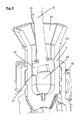
- the in the FIGS. 1 and 2 Part of a headlamp according to the invention shown from different sides comprises the drive shaft 1, 2 and a gear unit 3, which can be driven via the drive shaft.
- the drive shaft 1, 2 has two shaft parts, namely the first shaft part 1 and the second shaft part 2.
- the two shaft parts 1, 2 are connected to each other in the manner of a splined connection, but together do not form a splined shaft in the strict sense.
- the shaft parts are not only axially displaceable against each other and for the transmission of torques designed. Rather, the shaft parts 1, 2 are mutually pivotable. This is not the case with a splined shaft in the narrower sense.
- the first shaft part has a drive head 11, via which a torque can be introduced into the drive shaft 1, 2.
- a torque can be introduced into the drive shaft 1, 2.
- the drive head 11 is mounted in a part 41 of a housing 4 so that the first shaft part 1 can perform a wobbling motion.
- the part 41, on which the drive head 11 is mounted in the housing 4, is formed by a fork 41, which engages in a groove 113 in the drive head 11.
- the fork 41 had against the groove 113 so much game that the wobbling movement of the first shaft part 1 relative to the housing 4 is possible.
- conical sections 114, 115 are provided, which also allow a wobbling movement of the drive head 11 relative to a hollow cylindrical portion 42 of the housing 4. Between these conical sections 114, 115, a groove is provided, in which an O-ring 112 is inserted.
- the O-ring 112 allows sealing of the interior of the housing 4 from the environment of the housing. This is important so that no moisture, e.g. from an engine compartment can penetrate into the headlight.
- the possible pivot axes about which the drive head 11 can pivot relative to the housing 4 lie in the plane of the O-ring 112.
- the drive head 11 is followed by a shaft shank which terminates at a first end of the shaft.
- an external hexagon 12 is provided (see FIGS. 3 to 6 ).
- the hexagon socket 12 is arched or convex and immersed in an elongated hexagon socket 22 of the second shaft part 2 a.
- the second shaft part is rotatably mounted in a bearing portion 31 of the gear unit about its longitudinal axis. Compared to the first shaft part 1, the second shaft part 2 is formed very short. It has an output head 23 with a bevel gear, which cooperates with a bevel gear 32 of the gear unit 3 and transmits a rotational movement of the drive shaft 1, 2 to the bevel gear 32 of the gear unit 3.
- the first end of the second shaft part 2 adjoins the output head 23 of the second shaft part without any further transition.
- This second end of the shaft of the elongated hexagon socket 22 is provided.
- the crowned external hexagon 12 at the first end of the first shaft part 1 dips into the hexagon socket 22 a.
- the hexagon socket 12 is axially movable in the hexagon socket 22.
- the hexagon socket 12 and the associated shaft shaft 13, ie the entire first shaft part 1 with respect to the hexagon socket 22 or the entire second shaft part 2 can be pivoted so that the longitudinal axis of the first shaft part 1 and the second shaft part 2, the axes of rotation of the Shaft parts 1, 2 correspond, are inclined to each other.
- a funnel 21 at the opening of the hexagon socket 22 facilitates insertion of the first shaft part 1 during assembly of the drive shaft 1, 2 in the headlight.
- FIGS. 6 to 8 show different angular positions or inclinations of the first shaft part 1 to the second shaft part 2.
- the different inclinations are caused by the pivoting of the suspension element of the headlight.
- the different positions of the light unit can be seen at the different positions of the second shaft part 2 and the transmission unit 3.
- the gear unit 3 is fixedly attached to the to be adjusted (second) light unit.
Abstract
Description
- Die Erfindung betrifft einen Scheinwerfer mit einem Gehäuse, einem um die erste Achse gegenüber dem Gehäuse schwenkbaren Tragmittel, an der eine erste Lichteinheit angebracht sein kann, und einer zum Tragmittel um eine zweite Achse schwenkbaren zweiten Lichteinheit, wobei der Scheinwerfer eine Antriebswelle zum Schwenken der Lichteinheit um die zweite Achse aufweist, die über ein Getriebe mit der Lichteinheit gekoppelt ist, wobei die Antriebswelle zur Übertragung einer Drehbewegung von einem Antriebskopf der Antriebswelle zu einem Abtriebskopf der Antriebswelle geeignet und eingerichtet ist und wobei der Antriebskopf an dem Gehäuse gelagert ist.
- Ein derartiger Scheinwerfer kann als Hauptscheinwerfer in einem Kraftfahrzeug verwendet werden. Mit einem Hauptscheinwerfer eines Kraftfahrzeugs können verschiedene Lichtverteilungen erzeugt werden, um den Straßenraum vor dem Kraftfahrzeug zu beleuchten. Die bekanntesten Lichtverteilungen sind das Fernlicht und das Abblendlicht. Das Abblendlicht bei einem Kraftfahrzeughauptscheinwerfer ist so eingestellt, dass unterhalb einer Horizontlinie ein sich lang erstreckendes Band beleuchtet ist. Dieses Band wird von einer ersten Lichteinheit erzeugt. Außerdem wird ein kreissektorförmiger Bereich beleuchtet, der - bei Fahrzeugen für den Rechtsverkehr - rechts von der Mitte oberhalb der Horizontlinie zu finden ist. Dieser kreissektorförmige Bereich wird von einer zweiten Lichteinheit des Scheinwerfers erzeugt.
- Bei einem Scheinwerfer der eingangs genannten Art ist die erste Lichteinheit an dem in dem Gehäuse schwenkbaren Tragmittel angebracht. Diese erste Lichteinheit ist zusammen mit dem Tragmittel um die erste Achse schwenkbar. Ein Scheinwerfer mit einem Tragmittel und einer daran angebrachten ersten Lichteinheit ist aus der deutschen Offenlegungsschrift
DE 10 2007 040 728 A1 bekannt. Der dort offenbarte Scheinwerfer weist jedoch keine zweite Lichteinheit auf. - Die zweite Lichteinheit ist ebenfalls zusammen mit dem Tragmittel gegenüber dem Gehäuse um die erste Achse schwenkbar. Sie ist allerdings auch um eine zweite Achse gegenüber dem Treibmittel schwenkbar. Zum Einstellen des Abblendlichts werden die erste Lichteinheit und die zweite Lichteinheit geschwenkt, so dass die gewünschte Abblendlichtverteilung erreicht wird.
- Die Einstellung des Abblendlichts erfolgt nach der Montage des Scheinwerfers im Kraftfahrzeug. Bei der Einstellung wird zunächst der Scheinwerfer durch Schwenken des Tragmittels um die erste Achse, die horizontal verläuft, so eingestellt, dass das von der ersten Lichteinheit beleuchtete Band unterhalb der Horizontlinie zu finden ist. Gleichzeitig damit wird auch die zweite Lichteinheit so eingestellt, dass der kreissektorförmige Bereich unmittelbar oberhalb der Horizontlinie zu finden ist. Allerdings könnte der kreissektorförmige Bereich dann noch zu weit nach rechts oder zu weit nach links leuchten. Um dieses einzustellen wird dann die zweite Lichteinheit um die zweite Achse, die vertikal verläuft, gegenüber dem Tragmittel geschwenkt.
- Damit die zweite Lichteinheit um die zweite, horizontal verlaufende Achse geschwenkt werden kann, ist die Antriebswelle vorgesehen, in welche an dem Antriebskopf der Antriebswelle ein Drehmoment eingeleitet werden kann und die an dem Abtriebskopf das Drehmoment in das Getriebe überträgt, welches die Einstellung der zweiten Lichteinheit bewirkt. Der Antriebskopf der Antriebswelle ist dabei an dem Gehäuse des Scheinwerfers gelagert. Eine Schlüsselfläche an dem Antriebskopf ist von außerhalb des Gehäuses zugänglich. An der Schlüsselfläche kann ein Werkzeug angesetzt werden, um das Drehmoment in die Antriebswelle einzuleiten. Durch das Schwenken des Tragmittels um die erste Achse wird der Abtriebskopf der Antriebswelle allerdings gegenüber dem Antriebskopf verschoben. Diese Verschiebung wird bei bekannten Scheinwerfern durch flexible Wellen oder Kardangelenke ausgeglichen. Diese Lösungen sind allerdings kostenintensiv und aufwändig.
- Hier setzt die vorliegende Erfindung an.
- Der vorliegenden Erfindung liegt die Aufgabe zu Grunde einen Scheinwerfer der eingangs genannten Art so zu verbessern, dass die Verschiebung des Abtriebskopfes gegenüber dem Antriebskopf der Antriebswelle mit einfachen technischen Mitteln ausgeglichen werden kann.
- Diese Aufgabe wird erfindungsgemäß dadurch gelöst, dass die Antriebswelle einen ersten Wellenteil und einen zweiten Wellenteil aufweist, wobei die Wellenteile an ersten Enden zur Übertragung der Drehbewegung nach Art einer Vielkeilverbindung zueinander axial verschiebbar und drehfest mit einander verbunden sind und wobei sich eine zu übertragende Drehbewegung im ersten Wellenteil um eine erste Drehachse und im zweiten Wellenteil um eine zweite Drehachse vollzieht, und dass die Wellenteile um vorzugsweise mehrere Achsen senkrecht zur ersten Drehachse und zur zweiten Drehachse zueinander schwenkbar sind.
- Vielkeilverbindungen werden in Vielkeilwellen dazu benutzt, um Drehmomente zu übertragen aber gleichzeitig eine axiale Verschiebung des Antriebskopfes zum Abtriebskopf der Antriebswelle zu ermöglichen. Eine solche Vielkeilwelle ist beispielsweise aus der Druckschrift mit der Veröffentlichungsnummer
DE 30 02 143 C2 bekannt. Bei bekannten Vielkeilwellen ist jedoch ein Schwenken der die Vielkeilwellen bildenden Wellenteile um eine oder mehrere Achsen senkrecht zu den Drehachsen an Wellenteilen nicht möglich. Hierin unterscheidet sich die Antriebswelle einer erfindungsgemäßen Vorrichtung von einer bekannten Vielkeilwelle. Die Antriebsachse eines erfindungsgemäßen Scheinwerfers ist so eingerichtet, dass die Wellenteile zueinander geneigt werden können. Die Antriebswelle weist somit wenigstens einen Freiheitsgrad mehr auf als eine übliche Vielkeilwelle. Die Antriebswelle einer erfindungsgemäßen Vorrichtung kann also Einknicken. Dieses Einknicken ermöglicht das vertikale Schwenken des Abtriebskopfes der Antriebswelle gegenüber dem Antriebskopf durch das Schwenken des Tragmittels um die erste Achse. - Da ein erfindungsgemäßer Scheinwerfer nicht notwendigerweise eine erste Lichteinheit aufweisen muss, ist in den Ansprüchen die vorstehend als zweite Lichteinheit bezeichnete Einheit als Lichteinheit bezeichnet.
- Bei einem erfindungsgemäßen Scheinwerfer kann der erste Wellenteil für die Verbindung mit dem zweiten Wellenteil am ersten Ende eine Außenzahnung, einen Außensechskant oder dergleichen aufweisen. Der zweite Wellenteil ist für die Verbindung mit dem ersten Wellenteil dann dazu komplementär am ersten Ende mit einer Innenzahnung, einem Innensechskant oder dergleichen ausgestattet. Die zueinander komplementären Teile greifen in einander und können so Drehmomente von einem Wellenteil zum anderen Wellenteil übertragen, wobei die Wellenteile zueinander axial verschiebbar sind. Selbstverständlich ist es dabei auch denkbar, dass das zweite Wellenteil am ersten Ende eine Außenzahnung, einen Außensechskant oder dergleichen aufweist und der erste Wellenteil komplementär dazu mit Innenzahnung, einem Innensechskant oder dergleichen ausgestattet ist.
- Der erste Wellenteil kann am dem ersten Ende gegenüberliegenden Ende den Antriebskopf der Antriebswelle und der zweite Wellenteil am dem ersten Enden gegenüberliegenden Ende den Abtriebskopf aufweisen. Ebenso ist es möglich, dass der erste Wellenteil an dem dem ersten Ende gegenüberliegenden Ende den Abtriebskopf der Antriebswelle und der zweite Wellenteil an dem dem ersten Ende gegenüberliegenden Ende den Antriebskopf aufweist.
- Zum Erleichtern der Schwenkbewegung zwischen den Wellenteilen um eine der Achsen senkrecht zu der ersten Drehachse und der zweiten Drehachse kann die Außenzahnung, der Außensechskant oder dergleichen abgerundet sein. Dadurch kann die Innenzahnung, der Innensechskant oder dergleichen in verschiedenen Stellungen der Wellenteile zueinander tagential an der Außenzahnung, dem Außensechskant oder dergleichen anliegen.
- Der Antriebskopf eines erfindungsgemäßen Scheinwerfers kann einen Innensechskant als Schlüsselfläche aufweisen.
- Bei einem erfindungsgemäßen Scheinwerfer kann das zweite Wellenteil drehbar um die zweite Drehachse an der Lichteinheit gelagert sein.
- Der Abtriebskopf kann ein Kegelrad umfassen. Das Kegelrad des Abtriebkopfes kann ein Kegelrad des Getriebes kämmen.
- Anhand der beigefügten Zeichnungen wird die Erfindung nachfolgend näher erläutert. Dabei zeigt:
- Fig. 1
- in einer ersten perspektivischen Ansicht einen Teil eines erfindungsgemäβen Scheinwerfers umfassend eine Antriebswelle und eine Getriebeeinheit,
- Fig. 2
- in einer zweiten perspektivischen Ansicht den in
Figur 1 dargestellten Teil des Scheinwerfers, - Fig. 3
- einen Schnitt durch den erfindungsgemäßen Scheinwerfer einschließlich eines Schnittes durch die Antriebsachse und die Getriebeeinheit,
- Fig. 4
- ein Detail aus
Fig. 3 , nämlich eine Schnittansicht eines Antriebskopfes, - Fig. 5
- eine Schnittansicht einer Verbindung von einem ersten Wellenteil und einem zweiten Wellenteil der Antriebsachse,
- Fig. 6
- einen Schnitt durch den erfindungsgemäßen Scheinwerfer einschließlich eines Schnittes durch die Antriebsachse und die Getriebeeinheit mit einer ersten Winkelstellung der Wellenteile der Antriebswelle zueinander,
- Fig. 7
- einen Schnitt durch den erfindungsgemäßen Scheinwerfer einschließlich eines Schnittes durch die Antriebsachse und die Getriebeeinheit mit einer zweiten Winkelstellung der Wellenteile der Antriebswelle zueinander und
- Fig. 8
- einen Schnitt durch den erfindungsgemäßen Scheinwerfer einschließlich eines Schnittes durch die Antriebsachse und die Getriebeeinheit mit einer dritten Winkelstellung der Wellenteile der Antriebswelle zueinander,
- Der in den
Figuren 1 und2 von verschiedenen Seiten dargestellte Teil eines erfindungsgemäßen Scheinwerfers umfasst die Antriebswelle 1, 2 und eine Getriebeeinheit 3, die über die Antriebswelle angetrieben werden kann. - Die Antriebswelle 1, 2 hat zwei Wellenteile, nämlich den ersten Wellenteil 1 und den zweiten Wellenteil 2. Die beiden Wellenteile 1, 2 sind nach Art einer Vielkeilverbindung miteinander verbunden, bilden jedoch zusammen keine Vielkeilwelle im engeren Sinne. Im Unterschied zu einer Vielkeilwelle im engeren Sinne sind die Wellenteile nicht nur axial gegeneinander verschiebbar und zur Übertragung von Drehmomenten ausgelegt. Vielmehr sind die Wellenteile 1, 2 gegeneinander schwenkbar. Dieses ist bei einer Vielkeilwelle im engeren Sinne nicht der Fall.
- Der erste Wellenteil weist einen Antriebskopf 11 auf, über den ein Drehmoment in die Antriebswelle 1, 2 eingeleitet werden kann. An dem Antriebskopf 11 ist dazu eine Schlüsselfläche in Form eines Innensechskants 111 vorgesehen. Der Antriebskopf 11 ist in einem Teil 41 eines Gehäuses 4 so gelagert, dass der erste Wellenteil 1 eine Taumelbewegung ausführen kann. Das Teil 41, an dem der Antriebskopf 11 in dem Gehäuse 4 gelagert ist, wird durch eine Gabel 41 gebildet, die in einer Nut 113 im Antriebskopf 11 eingreift. Die Gabel 41 hatte dabei gegenüber der Nut 113 so viel Spiel, dass die Taumelbewegung des ersten Wellenteils 1 gegenüber dem Gehäuse 4 möglich ist. An dem Antriebskopf 11 sind konische Abschnitte 114, 115 vorgesehen, die ebenfalls eine Taumelbewegung des Antriebskopfes 11 gegenüber einem hohlzylindrischen Abschnitt 42 des Gehäuses 4 ermöglichen. Zwischen diesen konischen Abschnitten 114, 115 ist eine Nut vorgesehen, in welche ein O-Ring 112 eingesetzt ist. Der O-Ring 112 ermöglicht eine Abdichtung des Inneren des Gehäuses 4 gegenüber der Umgebung des Gehäuses. Dieses ist wichtig, damit keine Feuchtigkeit z.B. aus einem Motorraum in den Scheinwerfer eindringen kann. Die möglichen Schwenkachsen, um die der Antriebskopf 11 gegenüber dem Gehäuse 4 schwenken kann, liegen in der Ebene des O-Ringes 112.
- An den Antriebskopf 11 schließt sich ein Wellenschaft an der an einem ersten Ende der Welle endet. An dem ersten Ende der Welle ist ein Außensechskant 12 vorgesehen (siehe
Figur 3 bis 6 ). Der Außensechskant 12 ist gewölbt oder ballig ausgebildet und taucht in einen langgestreckten Innensechskant 22 des zweiten Wellenteils 2 ein. Der zweite Wellenteil ist in einem Lagerabschnitt 31 der Getriebeeinheit um seine Längsachse drehbar gelagert. Im Vergleich zu dem ersten Wellenteil 1 ist der zweite Wellenteil 2 sehr kurz ausgebildet. Er weist einen Abtriebskopf 23 mit einem Kegelrad auf, der mit einem Kegelrad 32 der Getriebeeinheit 3 zusammenwirkt und eine Drehbewegung der Antriebswelle 1, 2 auf das Kegelrad 32 der Getriebeeinheit 3 überträgt. An den Abtriebskopf 23 des zweiten Wellenteils schließt sich ohne weiteren Übergang das erste Ende des zweiten Wellenteils 2 an. In diesem zweiten Ende der Welle ist der lang gestreckte Innensechskant 22 vorgesehen. Das ballig ausgebildete Außensechskant 12 am ersten Ende des ersten Wellenteils 1 taucht in den Innensechskant 22 ein. Der Außensechskant 12 ist axial in dem Innensechskant 22 bewegbar. Außerdem kann der Außensechskant 12 und der mit diesem verbundene Wellenschaft 13, d.h. das gesamte erste Wellenteil 1 gegenüber dem Innensechskant 22 beziehungsweise dem gesamten zweiten Wellenteil 2 geschwenkt werden, so dass die Längsachse des ersten Wellenteils 1 und des zweiten Wellenteils 2, die den Drehachsen der Wellenteile 1, 2 entsprechen, zueinander geneigt sind. Ein Trichter 21 an der Öffnung des Innensechskants 22 erleichtert dass Einführen des ersten Wellenteils 1 bei der Montage der Antriebswelle 1, 2 in dem Scheinwerfer. - Die
Figuren 6 bis 8 zeigen verschiedene Winkelstellungen oder Neigungen des ersten Wellenteils 1 zum zweiten Wellenteil 2. Die unterschiedlichen Neigungen werden durch das Schwenken des Tragmittels des Scheinwerfers hervorgerufen. Die unterschiedlichen Stellungen der Lichteinheit sind an den unterschiedlichen Stellungen des zweiten Wellenteils 2 bzw. der Getriebeeinheit 3 erkennbar. Die Getriebeeinheit 3 ist fest an der zu verstellenden (zweiten) Lichteinheit angebracht. -
- 1
- erster Wellenteil
- 11
- Antriebskopf
- 111
- Innensechskant
- 112
- O-Ring
- 113
- Nut
- 114
- Konus
- 115
- Konus
- 12
- Außensechskant, erstes Ende
- 13
- Wellenschaft
- 2
- zweiter Wellenteil
- 21
- Trichter
- 22
- Innensechskant, erstes Ende
- 23
- Abtriebskopf, Kegelrad
- 3
- Getriebeeinheit
- 31
- Kegelrad
- 32
- Lagerabschnitt
- 4
- Gehäuse
- 41
- Gabel
Claims (9)
- Scheinwerfer mit einem Gehäuse (4), einem um die erste Achse gegenüber dem Gehäuse (4) schwenkbaren Tragmittel und einer zum Tragmittel um eine zweite Achse schwenkbaren Lichteinheit, wobei der Scheinwerfer eine Antriebswelle (1, 2) zum Schwenken der Lichteinheit um die zweite Achse aufweist, die über eine Getriebeeinheit (3) mit der Lichteinheit gekoppelt ist, wobei die Antriebswelle (1 ,2) zur Übertragung einer Drehbewegung von einem Antriebskopf (11) der Antriebswelle (1, 2) zu einem Abtriebskopf (23) der Antriebswelle (1, 2) geeignet und eingerichtet ist und wobei der Antriebskopf (11) an dem Gehäuse (4) gelagert ist,
dadurch gekennzeichnet,
dass die Antriebswelle (1, 2) einen ersten Wellenteil (1) und einen zweiten Wellenteil (2) aufweist, wobei die Wellenteile (1, 2) an ersten Enden (12, 22) zur Übertragung der Drehbewegung nach Art einer Vielkeilverbindung zueinander axial verschiebbar und drehfest mit einander verbunden sind und wobei sich eine zu übertragende Drehbewegung im ersten Wellenteil (1) um eine erste Drehachse und im zweiten Wellenteil (2) um eine zweite Drehachse vollzieht, und
dass die Wellenteile (1, 2) um vorzugsweise mehrere Achsen senkrecht zur ersten Drehachse und zur zweiten Drehachse zueinander schwenkbar sind. - Scheinwerfer nach Anspruch 1, dadurch gekennzeichnet, dass der erste Wellenteil (1) für die Verbindung mit dem zweiten Wellenteil (2) am ersten Ende eine Außenzahnung, einen Außensechskant (12) oder dergleichen aufweist und der zweite Wellenteil (2) für die Verbindung mit dem ersten Wellenteil (1) am ersten Ende dazu komplementär eine Innenzahnung, einen Innensechskant (22) oder dergleichen aufweist.
- Scheinwerfer nach Anspruch 1 oder 2, dadurch gekennzeichnet, dass der erste Wellenteil (1) am dem ersten Ende (12) gegenüberliegenden Ende den Antriebskopf (11) der Antriebswelle (1, 2) und der zweite Wellenteil (2) am dem ersten Enden (22) gegenüberliegenden Ende den Abtriebskopf (23) aufweist.
- Scheinwerfer nach Anspruch 2 oder 3, dadurch gekennzeichnet, dass die Außenzahnung, der Außensechskant (12) oder dergleichen zum Erleichtern der Schwenkbewegung eine der Achsen senkrecht zu der ersten Drehachse und der zweiten Drehachse abgerundet oder ballig ist, so dass die Innenzahnung, der Innensechskant (22) oder dergleichen in verschiedenen Stellungen der Wellenteile (1, 2) zueinander tagential an der Außenzahnung, dem Außensechskant (12) oder dergleichen anliegt.
- Scheinwerfer nach einem der Ansprüche 1 bis 4, dadurch gekennzeichnet, dass der Antriebskopf (11) einen Innensechskant (111) aufweist.
- Scheinwerfer nach einem der Ansprüche 1 bis 5, dadurch gekennzeichnet, dass das zweite Wellenteil (2) drehbar um die zweite Drehachse an der Lichteinheit gelagert ist.
- Scheinwerfer nach einem der Ansprüche 1 bis 6, dadurch gekennzeichnet, dass der Abtriebskopf (23) ein Kegelrad umfasst.
- Scheinwerfer nach Anspruch 7, dadurch gekennzeichnet, dass das Kegelrad (23) des Abtriebskopfes ein Kegelrad (31) der Getriebeeinheit (3) kämmt
- Scheinwerfer nach einem der Ansprüche 1 bis 8, dadurch gekennzeichnet, dass der Antriebskopf (11) eine Aufnahme für einen Dichtring, insbesondere einen O-Ring (112) aufweist, und dass der Dichtring den Antriebskopf (11) gegenüber dem Gehäuse (4) abdichtet.
Priority Applications (4)
| Application Number | Priority Date | Filing Date | Title |
|---|---|---|---|
| AT09177015T ATE542708T1 (de) | 2009-11-25 | 2009-11-25 | Scheinwerfer mit einem in einer ersten richtung schwenkbaren tragmittel und einer dazu in einer zweiten richtung schwenkbaren lichteinheit |
| EP09177015A EP2327583B1 (de) | 2009-11-25 | 2009-11-25 | Scheinwerfer mit einem in einer ersten Richtung schwenkbaren Tragmittel und einer dazu in einer zweiten Richtung schwenkbaren Lichteinheit |
| US12/951,132 US20110122642A1 (en) | 2009-11-25 | 2010-11-22 | Headlamp with a carrying element pivoting in a first direction and a light unit pivoting in a second direction |
| CN201010560120.9A CN102069748B (zh) | 2009-11-25 | 2010-11-25 | 前照灯 |
Applications Claiming Priority (1)
| Application Number | Priority Date | Filing Date | Title |
|---|---|---|---|
| EP09177015A EP2327583B1 (de) | 2009-11-25 | 2009-11-25 | Scheinwerfer mit einem in einer ersten Richtung schwenkbaren Tragmittel und einer dazu in einer zweiten Richtung schwenkbaren Lichteinheit |
Publications (2)
| Publication Number | Publication Date |
|---|---|
| EP2327583A1 true EP2327583A1 (de) | 2011-06-01 |
| EP2327583B1 EP2327583B1 (de) | 2012-01-25 |
Family
ID=42102345
Family Applications (1)
| Application Number | Title | Priority Date | Filing Date |
|---|---|---|---|
| EP09177015A Active EP2327583B1 (de) | 2009-11-25 | 2009-11-25 | Scheinwerfer mit einem in einer ersten Richtung schwenkbaren Tragmittel und einer dazu in einer zweiten Richtung schwenkbaren Lichteinheit |
Country Status (4)
| Country | Link |
|---|---|
| US (1) | US20110122642A1 (de) |
| EP (1) | EP2327583B1 (de) |
| CN (1) | CN102069748B (de) |
| AT (1) | ATE542708T1 (de) |
Families Citing this family (2)
| Publication number | Priority date | Publication date | Assignee | Title |
|---|---|---|---|---|
| CN110461650B (zh) * | 2017-03-20 | 2023-04-14 | 黑拉有限责任两合公司 | 用于前灯中的灯单元的光束水平的调节单元 |
| DE102022111131A1 (de) * | 2022-05-05 | 2023-11-09 | HELLA GmbH & Co. KGaA | Verstelleinheit für eine Lichteinheit und Scheinwerfer für ein Kraftfahrzeug |
Citations (6)
| Publication number | Priority date | Publication date | Assignee | Title |
|---|---|---|---|---|
| GB2109082A (en) * | 1981-11-06 | 1983-05-25 | Bosch Gmbh Robert | A headlamp for vehicles especially for motor vehicles |
| DE3002143C2 (de) | 1980-01-22 | 1983-09-22 | Danfoss A/S, 6430 Nordborg | Kupplung zum starren Verbinden einer vielfach genuteten Nabe mit einer Vielkeilwelle |
| US5214971A (en) * | 1992-03-19 | 1993-06-01 | Accurate Threaded Fasteners, Inc. | Angular adjustment mechanism |
| DE10325331A1 (de) * | 2003-06-04 | 2004-12-30 | Automotive Lighting Reutlingen Gmbh | Scheinwerfer |
| DE102005038829A1 (de) * | 2005-08-17 | 2007-07-12 | Automotive Lighting Reutlingen Gmbh | Vorrichtung zur Einstellung der Neigung eines Kraftfahrzeugscheinwerfers |
| DE102007040728A1 (de) | 2007-08-29 | 2009-03-05 | Automotive Lighting Reutlingen Gmbh | Fahrzeugscheinwerfer |
Family Cites Families (4)
| Publication number | Priority date | Publication date | Assignee | Title |
|---|---|---|---|---|
| US6257747B1 (en) * | 1999-06-10 | 2001-07-10 | John E. Burton | Headlamp adjuster |
| DE10257582A1 (de) * | 2002-12-09 | 2004-09-30 | Dorma Gmbh + Co. Kg | Stabilisierung für einen Führungsschlitten, insbesondere für eine von einem Linearantrieb bewegbare Schiebetür oder dergleichen |
| DE102006008363A1 (de) * | 2006-02-21 | 2007-08-30 | Schefenacker Vision Systems Germany Gmbh | Verstellsystem für Scheinwerfer |
| JP2009224037A (ja) * | 2008-03-13 | 2009-10-01 | Koito Mfg Co Ltd | 車輌用前照灯 |
-
2009
- 2009-11-25 AT AT09177015T patent/ATE542708T1/de active
- 2009-11-25 EP EP09177015A patent/EP2327583B1/de active Active
-
2010
- 2010-11-22 US US12/951,132 patent/US20110122642A1/en not_active Abandoned
- 2010-11-25 CN CN201010560120.9A patent/CN102069748B/zh not_active Expired - Fee Related
Patent Citations (6)
| Publication number | Priority date | Publication date | Assignee | Title |
|---|---|---|---|---|
| DE3002143C2 (de) | 1980-01-22 | 1983-09-22 | Danfoss A/S, 6430 Nordborg | Kupplung zum starren Verbinden einer vielfach genuteten Nabe mit einer Vielkeilwelle |
| GB2109082A (en) * | 1981-11-06 | 1983-05-25 | Bosch Gmbh Robert | A headlamp for vehicles especially for motor vehicles |
| US5214971A (en) * | 1992-03-19 | 1993-06-01 | Accurate Threaded Fasteners, Inc. | Angular adjustment mechanism |
| DE10325331A1 (de) * | 2003-06-04 | 2004-12-30 | Automotive Lighting Reutlingen Gmbh | Scheinwerfer |
| DE102005038829A1 (de) * | 2005-08-17 | 2007-07-12 | Automotive Lighting Reutlingen Gmbh | Vorrichtung zur Einstellung der Neigung eines Kraftfahrzeugscheinwerfers |
| DE102007040728A1 (de) | 2007-08-29 | 2009-03-05 | Automotive Lighting Reutlingen Gmbh | Fahrzeugscheinwerfer |
Also Published As
| Publication number | Publication date |
|---|---|
| CN102069748A (zh) | 2011-05-25 |
| ATE542708T1 (de) | 2012-02-15 |
| EP2327583B1 (de) | 2012-01-25 |
| US20110122642A1 (en) | 2011-05-26 |
| CN102069748B (zh) | 2014-11-19 |
Similar Documents
| Publication | Publication Date | Title |
|---|---|---|
| DE102014103028B3 (de) | Lenksäule für ein Kraftfahrzeug | |
| EP1926624B1 (de) | Antriebssystem für den einzelantrieb der beiden antriebsräder eines antriebsräderpaares | |
| DE102010027553B4 (de) | Lenkgetriebe mit Doppelritzel | |
| EP2112021A1 (de) | Scheinwerfer für Fahrzeuge | |
| EP3844046A1 (de) | Elektrisch verstellbare steer-by-wire lenksäule und kraftfahrzeug | |
| DE10162337B4 (de) | Längs eingebauter Antriebsstrang | |
| DE102006031390A1 (de) | Schaltgetriebe | |
| EP2776299B1 (de) | Getriebeeinheit | |
| DE102020211974A1 (de) | Drehmomentrückmeldungsanordnung für eine Fahrzeuglenksäule | |
| EP2327583B1 (de) | Scheinwerfer mit einem in einer ersten Richtung schwenkbaren Tragmittel und einer dazu in einer zweiten Richtung schwenkbaren Lichteinheit | |
| DE202010011852U1 (de) | Vorrichtung zur Einstellung der Distanz zwischen zwei Bauteilen | |
| DE102006024779B4 (de) | Antriebseinrichtung für ein verschwenkbar in einem Gehäuse gelagertes Lichtmodul sowie Scheinwerfer | |
| DE20213364U1 (de) | Antriebsvorrichtung | |
| DE10360245B4 (de) | Anhängekupplung für Personenkraftfahrzeuge | |
| EP2569557B1 (de) | Vorrichtung zur übertragung einer schaltbewegung | |
| DE102019108269B4 (de) | Luftleitvorrichtung mit Getriebe | |
| DE60302533T2 (de) | Kopplungssystem für zwei drehbare Teile und Montageverfahren desselben | |
| DE102017107887A1 (de) | Betätigungsvorrichtung für ein Kraftfahrzeuggetriebe und Schalteinheit | |
| DE3606073C2 (de) | Drehgelenk | |
| EP1880901A1 (de) | Scheinwerferverstellvorrichtung mit Getriebe | |
| EP1140583B1 (de) | Scheibenwischanlage für fahrzeug und verfahren zum betreiben eines wischhebelgestänges | |
| EP1321328B1 (de) | Längs eingebauter Antriebsstrang für ein Kraftfahrzeug | |
| DE102015202075B4 (de) | Schwenkmodul einer Anhängerkupplung | |
| DE102008011718B4 (de) | Scheinwerfer für ein Kraftfahrzeug mit einer Einstelleinrichtung | |
| DE102006003457A1 (de) | Lenkwelle für ein Lenkrad mit feststehender Lenknabe und einem Lenknabengetriebe mit Vorgelegewelle |
Legal Events
| Date | Code | Title | Description |
|---|---|---|---|
| PUAI | Public reference made under article 153(3) epc to a published international application that has entered the european phase |
Free format text: ORIGINAL CODE: 0009012 |
|
| 17P | Request for examination filed |
Effective date: 20100916 |
|
| AK | Designated contracting states |
Kind code of ref document: A1 Designated state(s): AT BE BG CH CY CZ DE DK EE ES FI FR GB GR HR HU IE IS IT LI LT LU LV MC MK MT NL NO PL PT RO SE SI SK SM TR |
|
| AX | Request for extension of the european patent |
Extension state: AL BA RS |
|
| RIC1 | Information provided on ipc code assigned before grant |
Ipc: B60Q 1/068 20060101AFI20110630BHEP |
|
| GRAP | Despatch of communication of intention to grant a patent |
Free format text: ORIGINAL CODE: EPIDOSNIGR1 |
|
| RIN1 | Information on inventor provided before grant (corrected) |
Inventor name: HERBERS, THOMAS |
|
| GRAS | Grant fee paid |
Free format text: ORIGINAL CODE: EPIDOSNIGR3 |
|
| GRAA | (expected) grant |
Free format text: ORIGINAL CODE: 0009210 |
|
| AK | Designated contracting states |
Kind code of ref document: B1 Designated state(s): AT BE BG CH CY CZ DE DK EE ES FI FR GB GR HR HU IE IS IT LI LT LU LV MC MK MT NL NO PL PT RO SE SI SK SM TR |
|
| REG | Reference to a national code |
Ref country code: GB Ref legal event code: FG4D Free format text: NOT ENGLISH |
|
| REG | Reference to a national code |
Ref country code: CH Ref legal event code: EP |
|
| REG | Reference to a national code |
Ref country code: AT Ref legal event code: REF Ref document number: 542708 Country of ref document: AT Kind code of ref document: T Effective date: 20120215 |
|
| REG | Reference to a national code |
Ref country code: IE Ref legal event code: FG4D |
|
| REG | Reference to a national code |
Ref country code: DE Ref legal event code: R096 Ref document number: 502009002555 Country of ref document: DE Effective date: 20120322 |
|
| REG | Reference to a national code |
Ref country code: NL Ref legal event code: VDEP Effective date: 20120125 |
|
| LTIE | Lt: invalidation of european patent or patent extension |
Effective date: 20120125 |
|
| PG25 | Lapsed in a contracting state [announced via postgrant information from national office to epo] |
Ref country code: HR Free format text: LAPSE BECAUSE OF FAILURE TO SUBMIT A TRANSLATION OF THE DESCRIPTION OR TO PAY THE FEE WITHIN THE PRESCRIBED TIME-LIMIT Effective date: 20120125 Ref country code: NO Free format text: LAPSE BECAUSE OF FAILURE TO SUBMIT A TRANSLATION OF THE DESCRIPTION OR TO PAY THE FEE WITHIN THE PRESCRIBED TIME-LIMIT Effective date: 20120425 Ref country code: IS Free format text: LAPSE BECAUSE OF FAILURE TO SUBMIT A TRANSLATION OF THE DESCRIPTION OR TO PAY THE FEE WITHIN THE PRESCRIBED TIME-LIMIT Effective date: 20120525 Ref country code: NL Free format text: LAPSE BECAUSE OF FAILURE TO SUBMIT A TRANSLATION OF THE DESCRIPTION OR TO PAY THE FEE WITHIN THE PRESCRIBED TIME-LIMIT Effective date: 20120125 Ref country code: LT Free format text: LAPSE BECAUSE OF FAILURE TO SUBMIT A TRANSLATION OF THE DESCRIPTION OR TO PAY THE FEE WITHIN THE PRESCRIBED TIME-LIMIT Effective date: 20120125 Ref country code: BG Free format text: LAPSE BECAUSE OF FAILURE TO SUBMIT A TRANSLATION OF THE DESCRIPTION OR TO PAY THE FEE WITHIN THE PRESCRIBED TIME-LIMIT Effective date: 20120425 |
|
| REG | Reference to a national code |
Ref country code: IE Ref legal event code: FD4D |
|
| PG25 | Lapsed in a contracting state [announced via postgrant information from national office to epo] |
Ref country code: LV Free format text: LAPSE BECAUSE OF FAILURE TO SUBMIT A TRANSLATION OF THE DESCRIPTION OR TO PAY THE FEE WITHIN THE PRESCRIBED TIME-LIMIT Effective date: 20120125 Ref country code: PT Free format text: LAPSE BECAUSE OF FAILURE TO SUBMIT A TRANSLATION OF THE DESCRIPTION OR TO PAY THE FEE WITHIN THE PRESCRIBED TIME-LIMIT Effective date: 20120525 Ref country code: PL Free format text: LAPSE BECAUSE OF FAILURE TO SUBMIT A TRANSLATION OF THE DESCRIPTION OR TO PAY THE FEE WITHIN THE PRESCRIBED TIME-LIMIT Effective date: 20120125 Ref country code: FI Free format text: LAPSE BECAUSE OF FAILURE TO SUBMIT A TRANSLATION OF THE DESCRIPTION OR TO PAY THE FEE WITHIN THE PRESCRIBED TIME-LIMIT Effective date: 20120125 Ref country code: GR Free format text: LAPSE BECAUSE OF FAILURE TO SUBMIT A TRANSLATION OF THE DESCRIPTION OR TO PAY THE FEE WITHIN THE PRESCRIBED TIME-LIMIT Effective date: 20120426 |
|
| PG25 | Lapsed in a contracting state [announced via postgrant information from national office to epo] |
Ref country code: CY Free format text: LAPSE BECAUSE OF FAILURE TO SUBMIT A TRANSLATION OF THE DESCRIPTION OR TO PAY THE FEE WITHIN THE PRESCRIBED TIME-LIMIT Effective date: 20120125 |
|
| PG25 | Lapsed in a contracting state [announced via postgrant information from national office to epo] |
Ref country code: SI Free format text: LAPSE BECAUSE OF FAILURE TO SUBMIT A TRANSLATION OF THE DESCRIPTION OR TO PAY THE FEE WITHIN THE PRESCRIBED TIME-LIMIT Effective date: 20120125 Ref country code: EE Free format text: LAPSE BECAUSE OF FAILURE TO SUBMIT A TRANSLATION OF THE DESCRIPTION OR TO PAY THE FEE WITHIN THE PRESCRIBED TIME-LIMIT Effective date: 20120125 Ref country code: DK Free format text: LAPSE BECAUSE OF FAILURE TO SUBMIT A TRANSLATION OF THE DESCRIPTION OR TO PAY THE FEE WITHIN THE PRESCRIBED TIME-LIMIT Effective date: 20120125 Ref country code: SE Free format text: LAPSE BECAUSE OF FAILURE TO SUBMIT A TRANSLATION OF THE DESCRIPTION OR TO PAY THE FEE WITHIN THE PRESCRIBED TIME-LIMIT Effective date: 20120125 Ref country code: IE Free format text: LAPSE BECAUSE OF FAILURE TO SUBMIT A TRANSLATION OF THE DESCRIPTION OR TO PAY THE FEE WITHIN THE PRESCRIBED TIME-LIMIT Effective date: 20120125 Ref country code: RO Free format text: LAPSE BECAUSE OF FAILURE TO SUBMIT A TRANSLATION OF THE DESCRIPTION OR TO PAY THE FEE WITHIN THE PRESCRIBED TIME-LIMIT Effective date: 20120125 Ref country code: CZ Free format text: LAPSE BECAUSE OF FAILURE TO SUBMIT A TRANSLATION OF THE DESCRIPTION OR TO PAY THE FEE WITHIN THE PRESCRIBED TIME-LIMIT Effective date: 20120125 |
|
| PG25 | Lapsed in a contracting state [announced via postgrant information from national office to epo] |
Ref country code: IT Free format text: LAPSE BECAUSE OF FAILURE TO SUBMIT A TRANSLATION OF THE DESCRIPTION OR TO PAY THE FEE WITHIN THE PRESCRIBED TIME-LIMIT Effective date: 20120125 Ref country code: SK Free format text: LAPSE BECAUSE OF FAILURE TO SUBMIT A TRANSLATION OF THE DESCRIPTION OR TO PAY THE FEE WITHIN THE PRESCRIBED TIME-LIMIT Effective date: 20120125 |
|
| PLBE | No opposition filed within time limit |
Free format text: ORIGINAL CODE: 0009261 |
|
| STAA | Information on the status of an ep patent application or granted ep patent |
Free format text: STATUS: NO OPPOSITION FILED WITHIN TIME LIMIT |
|
| 26N | No opposition filed |
Effective date: 20121026 |
|
| REG | Reference to a national code |
Ref country code: DE Ref legal event code: R097 Ref document number: 502009002555 Country of ref document: DE Effective date: 20121026 |
|
| PG25 | Lapsed in a contracting state [announced via postgrant information from national office to epo] |
Ref country code: ES Free format text: LAPSE BECAUSE OF FAILURE TO SUBMIT A TRANSLATION OF THE DESCRIPTION OR TO PAY THE FEE WITHIN THE PRESCRIBED TIME-LIMIT Effective date: 20120506 |
|
| BERE | Be: lapsed |
Owner name: HELLA KGAA HUECK & CO. Effective date: 20121130 |
|
| PG25 | Lapsed in a contracting state [announced via postgrant information from national office to epo] |
Ref country code: BE Free format text: LAPSE BECAUSE OF NON-PAYMENT OF DUE FEES Effective date: 20121130 |
|
| PG25 | Lapsed in a contracting state [announced via postgrant information from national office to epo] |
Ref country code: MT Free format text: LAPSE BECAUSE OF FAILURE TO SUBMIT A TRANSLATION OF THE DESCRIPTION OR TO PAY THE FEE WITHIN THE PRESCRIBED TIME-LIMIT Effective date: 20120125 |
|
| PGFP | Annual fee paid to national office [announced via postgrant information from national office to epo] |
Ref country code: GB Payment date: 20131120 Year of fee payment: 5 |
|
| PG25 | Lapsed in a contracting state [announced via postgrant information from national office to epo] |
Ref country code: TR Free format text: LAPSE BECAUSE OF FAILURE TO SUBMIT A TRANSLATION OF THE DESCRIPTION OR TO PAY THE FEE WITHIN THE PRESCRIBED TIME-LIMIT Effective date: 20120125 Ref country code: MC Free format text: LAPSE BECAUSE OF NON-PAYMENT OF DUE FEES Effective date: 20121130 |
|
| PG25 | Lapsed in a contracting state [announced via postgrant information from national office to epo] |
Ref country code: LU Free format text: LAPSE BECAUSE OF NON-PAYMENT OF DUE FEES Effective date: 20121125 Ref country code: SM Free format text: LAPSE BECAUSE OF FAILURE TO SUBMIT A TRANSLATION OF THE DESCRIPTION OR TO PAY THE FEE WITHIN THE PRESCRIBED TIME-LIMIT Effective date: 20120125 |
|
| REG | Reference to a national code |
Ref country code: CH Ref legal event code: PL |
|
| PG25 | Lapsed in a contracting state [announced via postgrant information from national office to epo] |
Ref country code: HU Free format text: LAPSE BECAUSE OF FAILURE TO SUBMIT A TRANSLATION OF THE DESCRIPTION OR TO PAY THE FEE WITHIN THE PRESCRIBED TIME-LIMIT Effective date: 20091125 Ref country code: CH Free format text: LAPSE BECAUSE OF NON-PAYMENT OF DUE FEES Effective date: 20131130 Ref country code: LI Free format text: LAPSE BECAUSE OF NON-PAYMENT OF DUE FEES Effective date: 20131130 |
|
| GBPC | Gb: european patent ceased through non-payment of renewal fee |
Effective date: 20141125 |
|
| PG25 | Lapsed in a contracting state [announced via postgrant information from national office to epo] |
Ref country code: MK Free format text: LAPSE BECAUSE OF FAILURE TO SUBMIT A TRANSLATION OF THE DESCRIPTION OR TO PAY THE FEE WITHIN THE PRESCRIBED TIME-LIMIT Effective date: 20120125 |
|
| REG | Reference to a national code |
Ref country code: FR Ref legal event code: PLFP Year of fee payment: 7 |
|
| PG25 | Lapsed in a contracting state [announced via postgrant information from national office to epo] |
Ref country code: GB Free format text: LAPSE BECAUSE OF NON-PAYMENT OF DUE FEES Effective date: 20141125 |
|
| PGFP | Annual fee paid to national office [announced via postgrant information from national office to epo] |
Ref country code: AT Payment date: 20151027 Year of fee payment: 7 |
|
| REG | Reference to a national code |
Ref country code: FR Ref legal event code: PLFP Year of fee payment: 8 |
|
| REG | Reference to a national code |
Ref country code: AT Ref legal event code: MM01 Ref document number: 542708 Country of ref document: AT Kind code of ref document: T Effective date: 20161125 |
|
| PG25 | Lapsed in a contracting state [announced via postgrant information from national office to epo] |
Ref country code: AT Free format text: LAPSE BECAUSE OF NON-PAYMENT OF DUE FEES Effective date: 20161125 |
|
| REG | Reference to a national code |
Ref country code: FR Ref legal event code: PLFP Year of fee payment: 9 |
|
| REG | Reference to a national code |
Ref country code: DE Ref legal event code: R081 Ref document number: 502009002555 Country of ref document: DE Owner name: HELLA GMBH & CO. KGAA, DE Free format text: FORMER OWNER: HELLA KGAA HUECK & CO., 59557 LIPPSTADT, DE |
|
| REG | Reference to a national code |
Ref country code: FR Ref legal event code: PLFP Year of fee payment: 10 |
|
| PGFP | Annual fee paid to national office [announced via postgrant information from national office to epo] |
Ref country code: FR Payment date: 20191014 Year of fee payment: 11 |
|
| PG25 | Lapsed in a contracting state [announced via postgrant information from national office to epo] |
Ref country code: FR Free format text: LAPSE BECAUSE OF NON-PAYMENT OF DUE FEES Effective date: 20201130 |
|
| PGFP | Annual fee paid to national office [announced via postgrant information from national office to epo] |
Ref country code: DE Payment date: 20230929 Year of fee payment: 15 |