EP2327577A1 - Dachspitze für ein Cabrioletfahrzeug - Google Patents
Dachspitze für ein Cabrioletfahrzeug Download PDFInfo
- Publication number
- EP2327577A1 EP2327577A1 EP10191773A EP10191773A EP2327577A1 EP 2327577 A1 EP2327577 A1 EP 2327577A1 EP 10191773 A EP10191773 A EP 10191773A EP 10191773 A EP10191773 A EP 10191773A EP 2327577 A1 EP2327577 A1 EP 2327577A1
- Authority
- EP
- European Patent Office
- Prior art keywords
- frame parts
- frame
- vehicle
- fastening means
- rooftop
- Prior art date
- Legal status (The legal status is an assumption and is not a legal conclusion. Google has not performed a legal analysis and makes no representation as to the accuracy of the status listed.)
- Granted
Links
- 238000004519 manufacturing process Methods 0.000 claims abstract description 8
- 238000000034 method Methods 0.000 claims abstract description 7
- 125000006850 spacer group Chemical group 0.000 claims description 10
- 238000004904 shortening Methods 0.000 description 6
- 229910052751 metal Inorganic materials 0.000 description 5
- 239000002184 metal Substances 0.000 description 5
- 239000004744 fabric Substances 0.000 description 3
- 238000003698 laser cutting Methods 0.000 description 3
- 239000000463 material Substances 0.000 description 3
- 229910052782 aluminium Inorganic materials 0.000 description 1
- XAGFODPZIPBFFR-UHFFFAOYSA-N aluminium Chemical compound [Al] XAGFODPZIPBFFR-UHFFFAOYSA-N 0.000 description 1
- 238000005266 casting Methods 0.000 description 1
- 239000002131 composite material Substances 0.000 description 1
- 230000003750 conditioning effect Effects 0.000 description 1
- 238000010276 construction Methods 0.000 description 1
- 230000000694 effects Effects 0.000 description 1
- 238000001125 extrusion Methods 0.000 description 1
- 238000003754 machining Methods 0.000 description 1
- 238000009417 prefabrication Methods 0.000 description 1
Images


Classifications
-
- B—PERFORMING OPERATIONS; TRANSPORTING
- B60—VEHICLES IN GENERAL
- B60J—WINDOWS, WINDSCREENS, NON-FIXED ROOFS, DOORS, OR SIMILAR DEVICES FOR VEHICLES; REMOVABLE EXTERNAL PROTECTIVE COVERINGS SPECIALLY ADAPTED FOR VEHICLES
- B60J7/00—Non-fixed roofs; Roofs with movable panels, e.g. rotary sunroofs
- B60J7/08—Non-fixed roofs; Roofs with movable panels, e.g. rotary sunroofs of non-sliding type, i.e. movable or removable roofs or panels, e.g. let-down tops or roofs capable of being easily detached or of assuming a collapsed or inoperative position
- B60J7/12—Non-fixed roofs; Roofs with movable panels, e.g. rotary sunroofs of non-sliding type, i.e. movable or removable roofs or panels, e.g. let-down tops or roofs capable of being easily detached or of assuming a collapsed or inoperative position foldable; Tensioning mechanisms therefor, e.g. struts
- B60J7/1226—Soft tops for convertible vehicles
- B60J7/1234—Soft tops for convertible vehicles characterised by arches, e.g. shape or material
- B60J7/1239—Front bow
Definitions
- the invention relates to a rooftop for a convertible vehicle, with a extending in the vehicle transverse direction between the lateral frame members of a hood linkage central part, which is connected on both sides via fastening means with the frame parts and can be brought in the vehicle longitudinal direction against a windshield frame to the plant. Furthermore, the invention relates to a method for producing such a rooftop.
- the DE 201 19 840 U1 discloses a connection between profiles of a vehicle body having a curved connection region, wherein at least one of the profiles has at least one material lug for forming the connection between the profiles.
- the profiles represent a roof top part and side frame profiles of a convertible top assembly for a convertible vehicle with a folding top, wherein the roof top part is fixedly connected to a front region of the side frame profiles to form a curved connecting portion.
- the at least one material lug is formed on the roof peak portion and extends beyond the forward end of the side frame profile toward a windshield frame.
- the invention has the object to be able to reduce the tool costs for the production of a rooftop in small series of vehicles.
- the roof top according to the invention for a convertible vehicle comprises a center part extending in the vehicle transverse direction between lateral frame parts of a top linkage, which is connected on both sides via fastening means with the frame parts and can be brought into abutment against a windshield frame in the vehicle longitudinal direction, wherein the prefabricated in the vehicle longitudinal direction with an excess length middle part in Connected with the frame parts state to the windshield frame is shortened fitting.
- the middle part according to the invention By prefabricating the middle part according to the invention with an excess length in the vehicle longitudinal direction, it is possible to use the central part for different types of vehicles can.
- the same tool for making the middle part is usable for the different types of vehicles, so that the tool cost can be reduced.
- the prefabrication of the middle part with excess length this is adapted to the respective vehicle type by shortening. Although resulting from the shortening additional manufacturing costs, but these are significantly lower in small batches than the cost of a new tool for making a rooftop.
- the prefabricated middle part has in particular on its connection side to the windshield frame out the excess length.
- the shortening is done eg by laser cutting.
- the other sides of the prefabricated middle part are already designed to fit and can therefore remain unprocessed.
- the shortening of the prefabricated middle part takes place in particular only on the connection side to the windshield frame.
- the width of the middle part is preferably smaller than the distance between the frame parts, wherein the lateral distances between the central part and the frame parts are completely or at least partially bridged by the fastening means, which are made in particular as separate components.
- the fastening means are made in particular as separate components.
- the lateral distances between the middle part and the frame parts are preferably bridged by adapter pieces, which are manufactured in particular as separate components and preferably cover the fastening means.
- the adapters thus serve as coverage of the lateral distances between the middle part and the frame parts.
- the adapters give the rooftop a desired shape in their lateral edge regions.
- a tool for producing the adapter pieces is significantly cheaper than a tool for producing a rooftop.
- the adapters are e.g. made of plastic, metal or a combination of both materials.
- the fastening means are preferably materially connected to the central part, in particular welded thereto. Furthermore, the fastening means are preferably releasably connected to the frame parts, in particular bolted to the frame parts. Preferably, the fastening means are each formed as an angle piece. In particular, the fastening means are made of metal.
- the fastening means are connected to the frame parts with the interposition of one or more spacers, so that tolerances can be compensated, which can occur when fastening the fastening means to the central part.
- the lateral distances between the middle part and the frame parts are thus bridged by the fastening means and by the spacer or spacers. If no spacer is required, the lateral distances between the middle part and the frame parts are bridged by the fastening means.
- the spacers may e.g. each be designed as a washer or the like. Since the mounting location of the fastening means is adaptable to the respective vehicle type at the central part and, if appropriate, spacers are used, identical fastening means can be used for different types of vehicle. This also allows the costs to be reduced.
- the middle part sits in the transverse direction preferably centrally between the frame parts.
- the middle part is curved at least partially formed.
- the middle part is manufactured as a sheet metal part, as an aluminum die-cast part and / or as a composite extruded profile.
- the middle part consists of metal.
- the top linkage is preferably part of a top, in particular a folding top, which is preferably covered with fabric.
- the roof top according to the invention is preferably used for a soft-top hood.
- the hood covers in a closed state in particular a passenger compartment of the vehicle and is in an open State convertible, in which the top is stored in particular in a convertible top compartment.
- the top linkage is preferably movably mounted on a body of the vehicle.
- the lateral frame parts extend in the closed state of the top in particular in or substantially in the vehicle longitudinal direction.
- the convertible vehicle is preferably a motor vehicle.
- the rooftop according to the invention preferably comprises a universally usable central part, which can be used for different types or derivatives of the same base vehicle.
- the middle part is e.g. formed in sheet metal construction as a bent extrusion or as a casting.
- the starting geometry of the central part has an excess on the connection side to the windshield frame, wherein the connection side, for example, to adapt to the windshield geometry of the respective vehicle type. by laser cutting, is processed.
- the remaining sides of the middle part preferably remain unprocessed.
- a machining of the upper side of the central part is not required, since the curvature of the front roof areas in the vehicle transverse direction is preferably the same for the different types (derivatives) for which the middle part can be used.
- the lateral connections to the frame parts on the left and on the right side of the middle part are preferably made via fastening means and adapters.
- the adapter pieces may for example consist of plastic and are preferably made for the respective vehicle type.
- the advantage of the invention lies in particular in the saving of operating costs, which have a relatively strong effect on the cost of the respective vehicle type, in particular for small quantities.
- Making multiple sets of tools for the entire rooftops of different vehicle types is considerably more expensive than just making relatively small tools for the side Adapterstschreibe. In this way, tooling costs for the middle part can be allocated to several vehicle types.
- the invention further relates to a method for producing a rooftop for a convertible vehicle, wherein a in the vehicle transverse direction between the lateral frame members of a top link extending and brought in the vehicle longitudinal direction against a windshield frame for conditioning or bringable center part is connected on both sides via fastening means with the frame parts, and wherein the middle part prefabricated in the vehicle longitudinal direction with an excess length and shortened to fit the windshield frame before connecting with the frame parts.
- the rooftop manufactured by means of the method is in particular a rooftop according to the invention and can be developed in accordance with all embodiments described in this connection.
- the middle part is made with a smaller width than the distance between the compassionteilten, wherein the lateral distances between the central part and the frame part by the fastening means are completely or at least partially bridged, which are made in particular as separate components.
- the fastening means are connected to the frame parts with the interposition of one or more spacers.
- the lateral distances between the middle part and the frame parts are preferably bridged by adapter pieces, which are manufactured in particular as separate components and preferably cover the fastening means.
- the middle part is preferably arranged centrally between the frame parts in the transverse direction.
- fastening means, adapters and / or spacers described in connection with the method can be developed according to all embodiments described in connection with the roof top according to the invention.
- Fig. 1 is a perspective view of a convertible vehicle 1 can be seen, which has a body 2 and a passenger compartment 3 covering the top 4, which is adjacent to a windshield frame 5.
- the top 4 shown in the closed state can be opened and stored in a schematically indicated top compartment 6 in the rear of the vehicle 1.
- the top 4 includes a hood frame 7 (see Fig. 2 ), which is covered with a fabric 8.
- Fig. 2 is a perspective view of the hood frame 7 can be seen, the fabric covering has been omitted.
- the linkage 7 is movably supported by means of bearings 9 on the body 2 and has at its front end two frame parts 10 and 11, on which a between this rooftop 12, which extends in the vehicle transverse direction y, is fastened to the windshield frame 5 in the closed state of the top 4.
- the roof top 12 comprises a central part 13 and two adapter pieces 14 and 15, between which the middle part 13 is arranged.
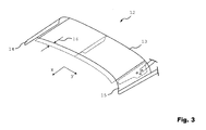
- Fig. 3 is a partial perspective bottom view of the roof top 12 can be seen, the center part 13 is prefabricated x before mounting on the hood frame 7 on its the windshield frame 5 facing the connection side with an excess length 16 in the vehicle longitudinal direction.
- the only schematically indicated excess length 16 is in the mounted state of the central part 13 by shortening, for example by means of laser cutting, adapted to the contour of the windshield frame 5.
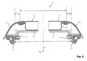
- Fig. 4 is a partial sectional view of the rooftop 12 along the in Fig. 2 shown section line AA, wherein the middle part 13 is secured by means of angle pieces formed fastening means 17 and 18 to the frame parts 10 and 11.
- the middle part 13 is composed of an upper plate 19 and a lower plate 20 which is fixed to the plate 19, and has a width b in the vehicle transverse direction y, which is smaller than the distance c between the two frame parts 10 and 11 in the vehicle transverse direction y is.
- the fastening means 17 and 18 are respectively welded to the lower plate 20 and each firmly connected via a screw 21 with the respective frame part 10 and 11 respectively. Between the fastening means 17 and 18 and the frame parts 10 and 11, a spacer 22 is arranged in each case, which is penetrated by the respective screw 21.
- the adapters 14 and 15 extend laterally outwardly from the central portion 13 and not only bridge the lateral distances d between the middle part 13 and the frame parts 10 and 11, but also cover these partially.
- the fastening means 17 and 18 are thus covered by the adapter pieces 14 and 15. Furthermore, in Fig. 4 the vehicle vertical direction z shown.
Landscapes
- Engineering & Computer Science (AREA)
- Mechanical Engineering (AREA)
- Body Structure For Vehicles (AREA)
Abstract
Description
- Die Erfindung betrifft eine Dachspitze für ein Cabrioletfahrzeug, mit einem sich in Fahrzeugquerrichtung zwischen seitlichen Rahmenteilen eines Verdeckgestänges erstreckenden Mittelteil, welches beidseitig über Befestigungsmittel mit den Rahmenteilen verbunden ist und in Fahrzeuglängsrichtung gegen einen Windschutzscheibenrahmen zur Anlage gebracht werden kann. Ferner betrifft die Erfindung ein Verfahren zur Fertigung einer solchen Dachspitze.
- Die
DE 201 19 840 U1 offenbart eine Verbindung zwischen Profilen eines Fahrzeugaufbaus mit einem gekrümmten Verbindungsbereich, wobei zumindest eines der Profile wenigstens eine Materialfahne zur Ausbildung der Verbindung zwischen den Profilen aufweist. Die Profile stellen ein Dachspitzenteil und seitliche Rahmenprofile eines Verdeckaufbaus für ein Cabrioletfahrzeug mit einem faltbaren Verdeck dar, wobei das Dachspitzenteil mit einem vorderen Bereich der seitlichen Rahmenprofile unter Ausbildung eines gekrümmten Verbindungsbereichs fest verbunden ist. Die wenigstens eine Materialfahne ist an dem Dachspitzenteil ausgebildet und erstreckt über das vordere Ende des seitlichen Rahmenprofiles hinaus in Richtung eines Windschutzscheibenrahmens. - Bei Kleinserien von Fahrzeugen stellt das Herstellen von Werkzeugen einen großen Kostenfaktor dar, sodass die Fertigung des Dachspitzenteils relativ teuer ist.
- Ausgehend hiervon liegt der Erfindung die Aufgabe zugrunde, bei Kleinserien von Fahrzeugen die Werkzeugkosten für die Fertigung einer Dachspitze reduzieren zu können.
- Diese Aufgabe wird erfindungsgemäß mit einer Dachspitze nach Anspruch 1 und mit einem Verfahren nach Anspruch 7 gelöst.
- Die erfindungsgemäße Dachspitze für ein Cabrioletfahrzeug umfasst ein sich in Fahrzeugquerrichtung zwischen seitlichen Rahmenteilen eines Verdeckgestänges erstreckendes Mittelteil, welches beidseitig über Befestigungsmittel mit den Rahmenteilen verbunden ist und in Fahrzeuglängsrichtung gegen einen Windschutzscheibenrahmen zur Anlage gebracht werden kann, wobei das in Fahrzeuglängsrichtung mit einer Überlänge vorgefertigte Mittelteil im mit den Rahmenteilen verbundenen Zustand zum Windschutzscheibenrahmen passend gekürzt ist.
- Es wurde erkannt, dass bei unterschiedlichen Cabrioletfahrzeugtypen desselben Herstellers die Abmessungen der Dachspitzen in Fahrzeugquerrichtung häufig relativ ähnlich sind. Ferner weisen die Dachspitzen in ihrem in Fahrzeugquerrichtung mittleren Bereich, abgesehen von der dem Windschutzscheibenrahmen zugewandten Anschlussseite, häufig dieselbe oder annähernd dieselbe Form auf.
- Durch das erfindungsgemäße Vorfertigen des Mittelteils mit einer Überlänge in Fahrzeuglängsrichtung ist es möglich, das Mittelteil für unterschiedliche Fahrzeugtypen einsetzen zu können. Somit ist für die unterschiedlichen Fahrzeugtypen dasselbe Werkzeug zur Herstellung des Mittelteils verwendbar, sodass die Werkzeugkosten reduziert werden können. Nach der Vorfertigung des Mittelteils mit Überlange wird dieses an den jeweiligen Fahrzeugtyp durch Kürzen angepasst. Zwar entstehen durch das Kürzen zusätzlich Fertigungskosten, diese sind bei Kleinserien aber deutlich geringer als die Herstellungskosten für ein neues Werkzeug zur Herstellung einer Dachspitze.
- Das vorgefertigte Mittelteil weist insbesondere an seiner Anschlussseite zum Windschutzscheibenrahmen hin die Überlänge auf. Durch das Kürzen wird somit das vorgefertigte Mittelteil an die Geometrie des Windschutzscheibenrahmens angepasst. Das Kürzen erfolgt z.B. durch Laserschneiden. Vorzugsweise sind oder werden, abgesehen von der Anschlussseite zum Windschutzscheibenrahmen hin, die übrigen Seiten des vorgefertigten Mittelteils bereits zur Montage passend ausgebildet und können somit unbearbeitet bleiben. Das Kürzen des vorgefertigten Mittelteils erfolgt insbesondere nur an der Anschlussseite zum Windschutzscheibenrahmen hin.
- Die Breite des Mittelteils ist bevorzugt kleiner als der Abstand zwischen den Rahmenteilen, wobei die seitlichen Abstände zwischen dem Mittelteil und den Rahmenteilen durch die Befestigungsmittel vollständig oder zumindest teilweise überbrückt sind, die insbesondere als separate Bauteile gefertigt sind. Somit ist es möglich, zum Überbrücken der Abstände zwischen dem Mittelteil und den Rahmenteilen die Befestigungsmittel an geeigneten Stellen an dem Mittelteil zu befestigen. Dadurch ist das Mittelteil für unterschiedliche Fahrzeugbreiten verwendbar. Auch dies begünstigt die Einsetzbarkeit des Mittelteils für unterschiedliche Fahrzeugtypen, die in ihrer Breite geringfügig variieren.
- Zusätzlich sind die seitlichen Abstände zwischen dem Mittelteil und den Rahmenteilen bevorzugt durch Adapterstücke überbrückt, die insbesondere als separate Bauteile gefertigt sind und vorzugsweise die Befestigungsmittel abdecken. Die Adapterstücke dienen somit als Abdeckung der seitlichen Abstände zwischen dem Mittelteil und den Rahmenteilen. Insbesondere verleihen die Adapterstücke der Dachspitze in ihren seitlichen Randbereichen eine gewünschte Form. Zwar sind die Adapterstücke an den jeweiligen Fahrzeugtyp anzupassen, ein Werkzeug zur Herstellung der Adapterstücke ist aber deutlich kostengünstiger als ein Werkzeug zur Herstellung einer Dachspitze. Die Adapterstücke bestehen z.B. aus Kunststoff, aus Metall oder aus einer Kombination beider Werkstoffe.
- Die Befestigungsmittel sind vorzugsweise stoffschlüssig mit dem Mittelteil verbunden, insbesondere mit diesem verschweißt. Ferner sind die Befestigungsmittel bevorzugt lösbar mit den Rahmenteilen verbunden, insbesondere mit den Rahmenteilen verschraubt. Vorzugsweise sind die Befestigungsmittel jeweils als Winkelstück ausgebildet. Insbesondere bestehen die Befestigungsmittel aus Metall.
- Bevorzugt sind die Befestigungsmittel mit den Rahmenteilen unter Zwischenschaltung einer oder mehrerer Distanzstücke verbunden, sodass Toleranzen ausgleichbar sind, die beim Befestigen der Befestigungsmittel an dem Mittelteil auftreten können. Die seitlichen Abstände zwischen dem Mittelteil und den Rahmenteilen sind somit durch die Befestigungsmittel und durch das oder die Distanzstücke überbrückt. Ist kein Distanzstück erforderlich, so sind die seitlichen Abstände zwischen dem Mittelteil und den Rahmenteilen durch die Befestigungsmittel überbrückt. Die Distanzstücke können z.B. jeweils als Unterlegscheibe oder dergleichen ausgebildet sein. Da der Befestigungsort der Befestigungsmittel an dem Mittelteil an den jeweiligen Fahrzeugtyp anpassbar ist und ggf. Distanzstücke verwendet werden, sind für unterschiedliche Fahrzeugtypen gleiche Befestigungsmittel einsetzbar. Auch hierdurch können die Kosten reduziert werden.
- Das Mittelteil sitzt in Querrichtung bevorzugt mittig zwischen den Rahmenteilen. Vorzugsweise ist das Mittelteil zumindest bereichsweise gekrümmt ausgebildet. Gemäß einer Ausgestaltung der Erfindung ist das Mittelteil als Blechteil, als Aluminiumdruckgussteil und/oder als zusammengesetztes Strangpressprofil gefertigt. Insbesondere besteht das Mittelteil aus Metall.
- Das Verdeckgestänge ist bevorzugt Teil eines Verdecks, insbesondere eines Faltverdecks, welches vorzugsweise mit Stoff bespannt ist. Die erfindungsgemäße Dachspitze wird bevorzugt für ein Softtop-Verdeck eingesetzt. Das Verdeck deckt in einem geschlossenen Zustand insbesondere einen Insassenraum des Fahrzeugs ab und ist in einen geöffneten Zustand überführbar, in welchem das Verdeck insbesondere in einem Verdeckkasten abgelegt ist. Das Verdeckgestänge ist bevorzugt bewegbar an einer Karosserie des Fahrzeugs gelagert. Die seitlichen Rahmenteile erstrecken sich im geschlossenen Zustand des Verdecks insbesondere in oder im Wesentlichen in Fahrzeuglängsrichtung. Das Cabrioletfahrzeug ist bevorzugt ein Kraftfahrzeug.
- Die erfindungsgemäße Dachspitze umfasst bevorzugt ein universell einsetzbares Mittelteil, welches für unterschiedliche Typen oder Derivate des gleichen Basisfahrzeugs einsetzbar ist. Das Mittelteil ist z.B. in Blechschalenbauweise als gebogenes Strangpressteil oder als Gussteil ausgebildet. Die Ausgangsgeometrie des Mittelteils weist an der Anschlussseite zum Windschutzscheibenrahmen ein Übermaß auf, wobei zur Anpassung an die Windschutzscheibengeometrie des jeweiligen Fahrzeugtyps die Anschlussseite, z.B. durch Laserschneiden, bearbeitet wird. Die übrigen Seiten des Mittelteils bleiben vorzugsweise unbearbeitet. Insbesondere ist eine Bearbeitung der Oberseite des Mittelteils nicht erforderlich, da die Wölbung der vorderen Dachbereiche in Fahrzeugquerrichtung bei den unterschiedlichen Typen (Derivaten), für die das Mittelteil verwendbar ist, vorzugsweise gleich ist. Die seitlichen Verbindungen zu den Rahmenteilen auf der linken und auf der rechten Seite des Mittelteils werden bevorzugt über Befestigungsmittel und Adapterstücke hergestellt. Die Adapterstücke können beispielsweise aus Kunststoff bestehen und werden bevorzugt für den jeweiligen Fahrzeugtyp angefertigt.
- Der Vorteil der Erfindung liegt insbesondere in der Einsparung von Betriebsmittelkosten, die sich insbesondere bei kleinen Stückzahlen relativ stark auf die Kosten des jeweiligen Fahrzeugtyps auswirken. Die Anfertigung mehrerer Werkzeugsätze für die kompletten Dachspitzen unterschiedlicher Fahrzeugtypen ist erheblich teurer als nur die Herstellung von relativ kleinen Werkzeugen für die seitlichen Adapterstrücke. Auf diese Weise können Werkzeugkosten für das Mittelteil auf mehrere Fahrzeugtypen umgelegt werden.
- Die Erfindung betrifft ferner ein Verfahren zur Fertigung einer Dachspitze für ein Cabrioletfahrzeug, wobei ein sich in Fahrzeugquerrichtung zwischen seitlichen Rahmenteilen eines Verdeckgestänges erstreckendes und in Fahrzeuglängsrichtung gegen einen Windschutzscheibenrahmen zur Anlage gebrachtes oder bringbares Mittelteil beidseitig über Befestigungsmittel mit den Rahmenteilen verbunden wird, und wobei das Mittelteil in Fahrzeuglängsrichtung mit einer Überlänge vorgefertigt und vor dem Verbinden mit den Rahmenteilen zum Windschutzscheibenrahmen passend gekürzt wird.
- Die mittels des Verfahrens gefertigte Dachspitze ist insbesondere eine erfindungsgemäße Dachspitze und kann gemäß allen in diesem Zusammenhang beschriebenen Ausgestaltungen weitergebildet sein.
- Bevorzugt wird das Mittelteil mit einer kleineren Breite als der Abstand zwischen den Rahmenteilten gefertigt, wobei die seitlichen Abstände zwischen dem Mittelteil und dem Rahmenteil durch die Befestigungsmittel ganz oder zumindest teilweise überbrückt werden, die insbesondere als separate Bauteile gefertigt werden. Gemäß einer Ausgestaltung der Erfindung werden die Befestigungsmittel mit den Rahmenteilen unter Zwischenschaltung einer oder mehrerer Distanzstücke verbunden.
- Zusätzlich werden die seitlichen Abstände zwischen dem Mittelteil und den Rahmenteilen bevorzugt durch Adapterstücke überbrückt, die insbesondere als separate Bauteile gefertigt werden und vorzugsweise die Befestigungsmittel abdecken. Das Mittelteil wird in Querrichtung bevorzugt mittig zwischen den Rahmenteilen angeordnet.
- Die im Zusammenhang mit dem Verfahren beschriebenen Befestigungsmittel, Adapterstücke und/oder Distanzstücke können gemäß allen im Zusammenhang mit der erfindungsgemäßen Dachspitze beschriebenen Ausgestaltungen weitergebildet sein.
- Die Erfindung wird nachfolgend anhand einer bevorzugten Ausführungsform unter Bezugnahme auf die Zeichnung beschrieben. In der Zeichnung zeigen:
- Fig. 1
- eine perspektivische Ansicht eines Cabrioletfahrzeugs mit geschlossenem Verdeck,
- Fig. 2
- eine perspektivische Ansicht eines eine Dachspit- ze gemäß einer Ausführungsform der Erfindung um- fassenden Verdeckgestänges,
- Fig. 3
- eine perspektivische Unteransicht der Dachspize und
- Fig. 4
- eine Schnittansicht durch die Dachspitze entlang der aus
Fig. 2 ersichtlichen Schnittlinie A-A. - Aus
Fig. 1 ist eine perspektivische Ansicht eines Cabrioletfahrzeugs 1 ersichtlich, welches eine Karosserie 2 und ein einen Insassenraum 3 abdeckendes Verdeck 4 aufweist, welches an einen Windschutzscheibenrahmen 5 angrenzt. Das im geschlossenen Zustand dargestellte Verdeck 4 kann geöffnet und in einem schematisch angedeuteten Verdeckkasten 6 im Heck des Fahrzeugs 1 abgelegt werden. Das Verdeck 4 umfasst ein Verdeckgestänge 7 (sieheFig. 2 ), welches mit einem Stoff 8 bespannt ist. - Aus
Fig. 2 ist eine perspektivische Ansicht des Verdeckgestänges 7 ersichtlich, wobei die Stoffbespannung weggelassen wurde. Das Gestänge 7 ist mittels Lager 9 an der Karosserie 2 bewegbar gelagert und weist an seinem vorderen Ende zwei Rahmenteile 10 und 11 auf, an denen eine sich zwischen diesen in Fahrzeugquerrichtung y erstreckende Dachspitze 12 befestigt ist, die im geschlossenen Zustand des Verdecks 4 an dem Windschutzscheibenrahmen 5 anliegt. Die Dachspitze 12 umfasst ein Mittelteil 13 und zwei Adapterstücke 14 und 15, zwischen denen das Mittelteil 13 angeordnet ist. - Aus
Fig. 3 ist eine teilweise perspektivische Unteransicht der Dachspitze 12 ersichtlich, deren Mittelteil 13 vor der Montage an das Verdeckgestänge 7 an seiner dem Windschutzscheibenrahmen 5 zugewandten Anschlussseite mit einer Überlänge 16 in Fahrzeuglängsrichtung x vorgefertigt ist. Die lediglich schematisch angedeutete Überlänge 16 ist im montierten Zustand des Mittelteils 13 durch Kürzen, z.B. mittels Laserschneiden, an die Kontur des Windschutzscheibenrahmens 5 angepasst. - Aus
Fig. 4 ist eine teilweise Schnittansicht der Dachspitze 12 entlang der inFig. 2 gezeigten Schnittlinie A-A ersichtlich, wobei das Mittelteil 13 über als Winkelstücke ausgebildete Befestigungsmittel 17 und 18 an den Rahmenteilen 10 und 11 befestigt ist. Das Mittelteil 13 ist aus einem oberen Blech 19 und aus einem unteren Blech 20, welches an dem Blech 19 befestigt ist, zusammengesetzt und weist in Fahrzeugquerrichtung y eine Breite b auf, die kleiner als der Abstand c zwischen den beiden Rahmenteilen 10 und 11 in Fahrzeugquerrichtung y ist. - Die Befestigungsmittel 17 und 18 sind jeweils an dem unteren Blech 20 angeschweißt und jeweils über eine Schraube 21 mit dem jeweiligen Rahmenteil 10 bzw. 11 fest verbunden. Zwischen den Befestigungsmitteln 17 und 18 und den Rahmenteilen 10 und 11 ist jeweils ein Distanzstück 22 angeordnet, welches von der jeweiligen Schraube 21 durchgriffen ist.
- Die Adapterstücke 14 und 15 erstrecken sich von dem Mittelteil 13 seitlich nach außen und überbrücken nicht nur die seitlichen Abstände d zwischen dem Mittelteil 13 und den Rahmenteilen 10 und 11, sondern decken auch diese teilweise ab. Die Befestigungsmittel 17 und 18 werden somit durch die Adapterstücke 14 und 15 abgedeckt. Ferner ist in
Fig. 4 die Fahrzeughochrichtung z dargestellt.
Claims (10)
- Dachspitze für ein Cabrioletfahrzeug, mit
einem sich in Fahrzeugquerrichtung (y) zwischen seitlichen Rahmenteilen (10, 11) eines Verdeckgestänges (7) erstreckenden Mittelteil (13), welches beidseitig über Befestigungsmittel (17, 18) mit den Rahmenteilen (10, 11) verbunden ist und in Fahrzeuglängsrichtung (x) gegen einen Windschutzscheibenrahmen (5) zur Anlage gebracht werden kann,
dadurch gekennzeichnet,
dass das in Fahrzeuglängsrichtung (x) mit einer Überlänge (16) vorgefertigte Mittelteil (13) im mit den Rahmenteilen (10, 11) verbundenen Zustand zum Windschutzscheibenrahmen (5) passend gekürzt ist. - Dachspitze nach Anspruch 1,
dadurch gekennzeichnet,
dass die Breite (b) des Mittelteils (13) kleiner als der Abstand (c) zwischen den Rahmenteilen (10, 11) ist und die seitlichen Abstände (d) zwischen dem Mittelteil (13) und den Rahmenteilen (10, 11) durch die als separate Bauteile gefertigten Befestigungsmittel (17, 18) zumindest teilweise überbrückt sind. - Dachspitze nach Anspruch 2,
dadurch gekennzeichnet,
dass die seitlichen Abstände (d) zwischen dem Mittelteil (13) und den Rahmenteilen (10, 11) durch als separate Bauteile gefertigte und die Befestigungsmittel (17, 18) abdeckende Adapterstücke (14, 15) überbrückt sind. - Dachspitze nach einem der vorangehenden Ansprüche,
dadurch gekennzeichnet,
dass die Befestigungsmittel (17, 18) mit den Rahmenteilen (10, 11) verschraubt und an dem Mittelteil (13) angeschweißt sind. - Dachspitze nach einem der vorangehenden Ansprüche,
dadurch gekennzeichnet,
dass die Befestigungsmittel (17, 18) mit den Rahmenteilen (10, 11) unter Zwischenschaltung einer oder mehrerer Distanzstücke (22) verbunden sind. - Dachspitze nach einem der vorangehenden Ansprüche,
dadurch gekennzeichnet,
dass das Mittelteil (13) in Fahrzeugquerrichtung (y) mittig zwischen den Rahmenteilen (10, 11) sitzt. - Verfahren zur Fertigung einer Dachspitze für ein Cabrioletfahrzeug, wobei
ein sich in Fahrzeugquerrichtung (y) zwischen seitlichen Rahmenteilen (10, 11) eines Verdeckgestänges (7) erstreckendes und in Fahrzeuglängsrichtung (x) gegen einen Windschutzscheibenrahmen (5) zur Anlage gebrachtes oder bringbares Mittelteil (13) beidseitig über Befestigungsmittel (17, 18) mit den Rahmenteilen (10, 11) verbunden wird,
dadurch gekennzeichnet,
dass das Mittelteil (13) in Fahrzeuglängsrichtung (x) mit einer Überlänge (16) vorgefertigt und vor dem Verbinden mit den Rahmenteilen (10, 11) zum Windschutzscheibenrahmen (5) passend gekürzt wird. - Verfahren nach Anspruch 7,
dadurch gekennzeichnet,
dass das Mittelteil (13) mit einer kleineren Breite (b) als der Abstand (c) zwischen den Rahmenteilen (10, 11) gefertigt wird, wobei die seitlichen Abstände (d) zwischen dem Mittelteil (13) und den Rahmenteilen (10, 11) durch die als separate Bauteile gefertigten Befestigungsmittel (17, 18) zumindest teilweise überbrückt werden. - Verfahren nach Anspruch 8,
dadurch gekennzeichnet,
dass die seitlichen Abstände (d) zwischen dem Mittelteil (13) und den Rahmenteilen (10, 11) durch als separate Bauteile gefertigte und die Befestigungsmittel (17, 18) abdeckende Adapterstücke (14, 15) überbrückt werden. - Verfahren nach einem der Ansprüche 7 bis 9,
dadurch gekennzeichnet,
dass das Mittelteil (13) in Fahrzeugquerrichtung (y) mittig zwischen den Rahmenteilen (10, 11) angeordnet wird.
Applications Claiming Priority (1)
| Application Number | Priority Date | Filing Date | Title |
|---|---|---|---|
| DE200910053700 DE102009053700A1 (de) | 2009-11-18 | 2009-11-18 | Dachspitze für ein Cabrioletfahrzeug |
Publications (2)
| Publication Number | Publication Date |
|---|---|
| EP2327577A1 true EP2327577A1 (de) | 2011-06-01 |
| EP2327577B1 EP2327577B1 (de) | 2013-01-16 |
Family
ID=43532724
Family Applications (1)
| Application Number | Title | Priority Date | Filing Date |
|---|---|---|---|
| EP20100191773 Not-in-force EP2327577B1 (de) | 2009-11-18 | 2010-11-18 | Dachspitze für ein Cabrioletfahrzeug |
Country Status (2)
| Country | Link |
|---|---|
| EP (1) | EP2327577B1 (de) |
| DE (1) | DE102009053700A1 (de) |
Families Citing this family (1)
| Publication number | Priority date | Publication date | Assignee | Title |
|---|---|---|---|---|
| DE102012106972A1 (de) * | 2012-07-31 | 2014-02-06 | Dr. Ing. H.C. F. Porsche Aktiengesellschaft | Verdecklager für ein Cabriolet-Fahrzeug |
Citations (3)
| Publication number | Priority date | Publication date | Assignee | Title |
|---|---|---|---|---|
| DE4001136A1 (de) * | 1990-01-17 | 1991-07-18 | Karmann Gmbh W | Verdeck fuer kabrio-fahrzeuge |
| US5884964A (en) * | 1996-02-26 | 1999-03-23 | Dura Convertible Systems, Inc. | Hybrid header for convertible top |
| DE20119840U1 (de) | 2001-12-06 | 2002-04-25 | Wilhelm Karmann GmbH, 49084 Osnabrück | Verbindung zwischen Profilen eines Fahrzeugaufbaus mit einem gekrümmten Verbindungsbereich |
-
2009
- 2009-11-18 DE DE200910053700 patent/DE102009053700A1/de not_active Withdrawn
-
2010
- 2010-11-18 EP EP20100191773 patent/EP2327577B1/de not_active Not-in-force
Patent Citations (3)
| Publication number | Priority date | Publication date | Assignee | Title |
|---|---|---|---|---|
| DE4001136A1 (de) * | 1990-01-17 | 1991-07-18 | Karmann Gmbh W | Verdeck fuer kabrio-fahrzeuge |
| US5884964A (en) * | 1996-02-26 | 1999-03-23 | Dura Convertible Systems, Inc. | Hybrid header for convertible top |
| DE20119840U1 (de) | 2001-12-06 | 2002-04-25 | Wilhelm Karmann GmbH, 49084 Osnabrück | Verbindung zwischen Profilen eines Fahrzeugaufbaus mit einem gekrümmten Verbindungsbereich |
Also Published As
| Publication number | Publication date |
|---|---|
| EP2327577B1 (de) | 2013-01-16 |
| DE102009053700A1 (de) | 2011-05-19 |
Similar Documents
| Publication | Publication Date | Title |
|---|---|---|
| DE68908798T2 (de) | Fahrzeugkarrosserie und deren Zusammenbauverfahren. | |
| DE102007006722C5 (de) | Träger für eine Karosserie eines Kraftwagens | |
| EP1928724B1 (de) | Kraftfahrzeugkarosserie mit einem adapterträger für ein dachmodul, adapterträger dafür, sowie verfahren zu deren herstellung | |
| DE19506160B4 (de) | Rahmenkonstruktion für Kraftfahrzeuge | |
| EP0561840B1 (de) | Mittelsäule an einer karosserie eines personenkraftwagens | |
| DE3346986A1 (de) | Wagenkasten | |
| DE102014221454A1 (de) | Vorderer Dachquerträger eines Fahrzeugrahmens und Verfahren zum Formen davon | |
| EP2948327B1 (de) | Zwischenschale für eine kraftfahrzeugtür, verfahren zur herstellung zwischenschale und tür für ein kraftfahrzeug | |
| DE1630211B2 (de) | Selbsttragende karosserie fuer personenkraftwagen | |
| DE4139303A1 (de) | Mittelsaeule an einer karosserie eines personenkraftwagens | |
| DE19939978B4 (de) | Verfahren zur Herstellung eines Dachaufbaus eines Fahrzeugs in Mischbauweise | |
| DE4027449A1 (de) | Fahrzeugtuer | |
| EP1921000B1 (de) | Boden vorne eines Karosserieunterbaus | |
| DE102018133048B3 (de) | Verbindungselement zur Befestigung eines Energiespeichers an einem Seitenschweller eines Kraftwagens | |
| DE102007061209B4 (de) | Seitentür für einen Kraftwagen | |
| DE102018006363B4 (de) | Dachmodul für ein Fahrzeugdach eines Personenkraftwagens | |
| DE19946013B4 (de) | Seitengerippe für eine selbsttragende Karosserie eines Kraftfahrzeuges | |
| DE102006052992A1 (de) | Rahmenstruktur für den Unterboden einer selbsttragenden Kraftfahrzeugkarosserie | |
| EP2327577B1 (de) | Dachspitze für ein Cabrioletfahrzeug | |
| DE102014206196A1 (de) | Dachrahmen für eine Fahrzeugkarosserie | |
| DE202007004123U1 (de) | Extrudierte Dicht- oder Abschlussleiste | |
| WO2005039960A1 (de) | Modular aufgebaute fahrerhausbaureihe | |
| DE102013002306A1 (de) | Fahrzeugsäule, insbesondere B-Säule eines Kraftfahrzeuges | |
| DE102004044056A1 (de) | Modulträger aus Leichtmetall-Strangpresskomponenten für ein Fahrzeug | |
| DE10105168A1 (de) | Fahrzeugdach |
Legal Events
| Date | Code | Title | Description |
|---|---|---|---|
| PUAI | Public reference made under article 153(3) epc to a published international application that has entered the european phase |
Free format text: ORIGINAL CODE: 0009012 |
|
| AK | Designated contracting states |
Kind code of ref document: A1 Designated state(s): AL AT BE BG CH CY CZ DE DK EE ES FI FR GB GR HR HU IE IS IT LI LT LU LV MC MK MT NL NO PL PT RO RS SE SI SK SM TR |
|
| AX | Request for extension of the european patent |
Extension state: BA ME |
|
| 17P | Request for examination filed |
Effective date: 20111201 |
|
| RIC1 | Information provided on ipc code assigned before grant |
Ipc: B60J 7/12 20060101AFI20120510BHEP |
|
| GRAP | Despatch of communication of intention to grant a patent |
Free format text: ORIGINAL CODE: EPIDOSNIGR1 |
|
| GRAS | Grant fee paid |
Free format text: ORIGINAL CODE: EPIDOSNIGR3 |
|
| GRAA | (expected) grant |
Free format text: ORIGINAL CODE: 0009210 |
|
| AK | Designated contracting states |
Kind code of ref document: B1 Designated state(s): AL AT BE BG CH CY CZ DE DK EE ES FI FR GB GR HR HU IE IS IT LI LT LU LV MC MK MT NL NO PL PT RO RS SE SI SK SM TR |
|
| REG | Reference to a national code |
Ref country code: GB Ref legal event code: FG4D Free format text: NOT ENGLISH |
|
| REG | Reference to a national code |
Ref country code: CH Ref legal event code: EP |
|
| REG | Reference to a national code |
Ref country code: IE Ref legal event code: FG4D Free format text: LANGUAGE OF EP DOCUMENT: GERMAN |
|
| REG | Reference to a national code |
Ref country code: AT Ref legal event code: REF Ref document number: 593690 Country of ref document: AT Kind code of ref document: T Effective date: 20130215 Ref country code: CH Ref legal event code: EP |
|
| REG | Reference to a national code |
Ref country code: DE Ref legal event code: R096 Ref document number: 502010002115 Country of ref document: DE Effective date: 20130307 |
|
| RAP2 | Party data changed (patent owner data changed or rights of a patent transferred) |
Owner name: VALMET AUTOMOTIVE OY |
|
| REG | Reference to a national code |
Ref country code: NL Ref legal event code: VDEP Effective date: 20130116 |
|
| REG | Reference to a national code |
Ref country code: LT Ref legal event code: MG4D |
|
| PG25 | Lapsed in a contracting state [announced via postgrant information from national office to epo] |
Ref country code: ES Free format text: LAPSE BECAUSE OF FAILURE TO SUBMIT A TRANSLATION OF THE DESCRIPTION OR TO PAY THE FEE WITHIN THE PRESCRIBED TIME-LIMIT Effective date: 20130427 Ref country code: NO Free format text: LAPSE BECAUSE OF FAILURE TO SUBMIT A TRANSLATION OF THE DESCRIPTION OR TO PAY THE FEE WITHIN THE PRESCRIBED TIME-LIMIT Effective date: 20130416 Ref country code: LT Free format text: LAPSE BECAUSE OF FAILURE TO SUBMIT A TRANSLATION OF THE DESCRIPTION OR TO PAY THE FEE WITHIN THE PRESCRIBED TIME-LIMIT Effective date: 20130116 Ref country code: IS Free format text: LAPSE BECAUSE OF FAILURE TO SUBMIT A TRANSLATION OF THE DESCRIPTION OR TO PAY THE FEE WITHIN THE PRESCRIBED TIME-LIMIT Effective date: 20130516 Ref country code: SE Free format text: LAPSE BECAUSE OF FAILURE TO SUBMIT A TRANSLATION OF THE DESCRIPTION OR TO PAY THE FEE WITHIN THE PRESCRIBED TIME-LIMIT Effective date: 20130116 Ref country code: BG Free format text: LAPSE BECAUSE OF FAILURE TO SUBMIT A TRANSLATION OF THE DESCRIPTION OR TO PAY THE FEE WITHIN THE PRESCRIBED TIME-LIMIT Effective date: 20130416 |
|
| PG25 | Lapsed in a contracting state [announced via postgrant information from national office to epo] |
Ref country code: PT Free format text: LAPSE BECAUSE OF FAILURE TO SUBMIT A TRANSLATION OF THE DESCRIPTION OR TO PAY THE FEE WITHIN THE PRESCRIBED TIME-LIMIT Effective date: 20130516 Ref country code: SI Free format text: LAPSE BECAUSE OF FAILURE TO SUBMIT A TRANSLATION OF THE DESCRIPTION OR TO PAY THE FEE WITHIN THE PRESCRIBED TIME-LIMIT Effective date: 20130116 Ref country code: PL Free format text: LAPSE BECAUSE OF FAILURE TO SUBMIT A TRANSLATION OF THE DESCRIPTION OR TO PAY THE FEE WITHIN THE PRESCRIBED TIME-LIMIT Effective date: 20130116 Ref country code: FI Free format text: LAPSE BECAUSE OF FAILURE TO SUBMIT A TRANSLATION OF THE DESCRIPTION OR TO PAY THE FEE WITHIN THE PRESCRIBED TIME-LIMIT Effective date: 20130116 Ref country code: GR Free format text: LAPSE BECAUSE OF FAILURE TO SUBMIT A TRANSLATION OF THE DESCRIPTION OR TO PAY THE FEE WITHIN THE PRESCRIBED TIME-LIMIT Effective date: 20130417 Ref country code: NL Free format text: LAPSE BECAUSE OF FAILURE TO SUBMIT A TRANSLATION OF THE DESCRIPTION OR TO PAY THE FEE WITHIN THE PRESCRIBED TIME-LIMIT Effective date: 20130116 Ref country code: LV Free format text: LAPSE BECAUSE OF FAILURE TO SUBMIT A TRANSLATION OF THE DESCRIPTION OR TO PAY THE FEE WITHIN THE PRESCRIBED TIME-LIMIT Effective date: 20130116 |
|
| PG25 | Lapsed in a contracting state [announced via postgrant information from national office to epo] |
Ref country code: HR Free format text: LAPSE BECAUSE OF FAILURE TO SUBMIT A TRANSLATION OF THE DESCRIPTION OR TO PAY THE FEE WITHIN THE PRESCRIBED TIME-LIMIT Effective date: 20130116 Ref country code: RS Free format text: LAPSE BECAUSE OF FAILURE TO SUBMIT A TRANSLATION OF THE DESCRIPTION OR TO PAY THE FEE WITHIN THE PRESCRIBED TIME-LIMIT Effective date: 20130116 |
|
| PG25 | Lapsed in a contracting state [announced via postgrant information from national office to epo] |
Ref country code: CZ Free format text: LAPSE BECAUSE OF FAILURE TO SUBMIT A TRANSLATION OF THE DESCRIPTION OR TO PAY THE FEE WITHIN THE PRESCRIBED TIME-LIMIT Effective date: 20130116 Ref country code: DK Free format text: LAPSE BECAUSE OF FAILURE TO SUBMIT A TRANSLATION OF THE DESCRIPTION OR TO PAY THE FEE WITHIN THE PRESCRIBED TIME-LIMIT Effective date: 20130116 Ref country code: EE Free format text: LAPSE BECAUSE OF FAILURE TO SUBMIT A TRANSLATION OF THE DESCRIPTION OR TO PAY THE FEE WITHIN THE PRESCRIBED TIME-LIMIT Effective date: 20130116 Ref country code: SK Free format text: LAPSE BECAUSE OF FAILURE TO SUBMIT A TRANSLATION OF THE DESCRIPTION OR TO PAY THE FEE WITHIN THE PRESCRIBED TIME-LIMIT Effective date: 20130116 Ref country code: RO Free format text: LAPSE BECAUSE OF FAILURE TO SUBMIT A TRANSLATION OF THE DESCRIPTION OR TO PAY THE FEE WITHIN THE PRESCRIBED TIME-LIMIT Effective date: 20130116 |
|
| PLBE | No opposition filed within time limit |
Free format text: ORIGINAL CODE: 0009261 |
|
| STAA | Information on the status of an ep patent application or granted ep patent |
Free format text: STATUS: NO OPPOSITION FILED WITHIN TIME LIMIT |
|
| PG25 | Lapsed in a contracting state [announced via postgrant information from national office to epo] |
Ref country code: CY Free format text: LAPSE BECAUSE OF FAILURE TO SUBMIT A TRANSLATION OF THE DESCRIPTION OR TO PAY THE FEE WITHIN THE PRESCRIBED TIME-LIMIT Effective date: 20130116 |
|
| 26N | No opposition filed |
Effective date: 20131017 |
|
| PG25 | Lapsed in a contracting state [announced via postgrant information from national office to epo] |
Ref country code: IT Free format text: LAPSE BECAUSE OF FAILURE TO SUBMIT A TRANSLATION OF THE DESCRIPTION OR TO PAY THE FEE WITHIN THE PRESCRIBED TIME-LIMIT Effective date: 20130116 |
|
| REG | Reference to a national code |
Ref country code: DE Ref legal event code: R097 Ref document number: 502010002115 Country of ref document: DE Effective date: 20131017 |
|
| BERE | Be: lapsed |
Owner name: WILHELM KARMANN G.M.B.H. Effective date: 20131130 |
|
| PG25 | Lapsed in a contracting state [announced via postgrant information from national office to epo] |
Ref country code: MC Free format text: LAPSE BECAUSE OF FAILURE TO SUBMIT A TRANSLATION OF THE DESCRIPTION OR TO PAY THE FEE WITHIN THE PRESCRIBED TIME-LIMIT Effective date: 20130116 |
|
| REG | Reference to a national code |
Ref country code: IE Ref legal event code: MM4A |
|
| PG25 | Lapsed in a contracting state [announced via postgrant information from national office to epo] |
Ref country code: BE Free format text: LAPSE BECAUSE OF NON-PAYMENT OF DUE FEES Effective date: 20131130 |
|
| PG25 | Lapsed in a contracting state [announced via postgrant information from national office to epo] |
Ref country code: IE Free format text: LAPSE BECAUSE OF NON-PAYMENT OF DUE FEES Effective date: 20131118 |
|
| REG | Reference to a national code |
Ref country code: DE Ref legal event code: R082 Ref document number: 502010002115 Country of ref document: DE Representative=s name: KRONTHALER, SCHMIDT & COLL. PATENTANWALTSKANZL, DE |
|
| REG | Reference to a national code |
Ref country code: DE Ref legal event code: R082 Ref document number: 502010002115 Country of ref document: DE Representative=s name: KRONTHALER, SCHMIDT & COLL. PATENTANWALTSKANZL, DE Effective date: 20141121 Ref country code: DE Ref legal event code: R081 Ref document number: 502010002115 Country of ref document: DE Owner name: VALMET AUTOMOTIVE OY, FI Free format text: FORMER OWNER: WILHELM KARMANN GMBH, 49084 OSNABRUECK, DE Effective date: 20141121 |
|
| PGFP | Annual fee paid to national office [announced via postgrant information from national office to epo] |
Ref country code: DE Payment date: 20141120 Year of fee payment: 5 Ref country code: GB Payment date: 20141120 Year of fee payment: 5 |
|
| PGFP | Annual fee paid to national office [announced via postgrant information from national office to epo] |
Ref country code: FR Payment date: 20141118 Year of fee payment: 5 |
|
| PG25 | Lapsed in a contracting state [announced via postgrant information from national office to epo] |
Ref country code: SM Free format text: LAPSE BECAUSE OF FAILURE TO SUBMIT A TRANSLATION OF THE DESCRIPTION OR TO PAY THE FEE WITHIN THE PRESCRIBED TIME-LIMIT Effective date: 20130116 |
|
| PG25 | Lapsed in a contracting state [announced via postgrant information from national office to epo] |
Ref country code: TR Free format text: LAPSE BECAUSE OF FAILURE TO SUBMIT A TRANSLATION OF THE DESCRIPTION OR TO PAY THE FEE WITHIN THE PRESCRIBED TIME-LIMIT Effective date: 20130116 |
|
| REG | Reference to a national code |
Ref country code: CH Ref legal event code: PL |
|
| PG25 | Lapsed in a contracting state [announced via postgrant information from national office to epo] |
Ref country code: CH Free format text: LAPSE BECAUSE OF NON-PAYMENT OF DUE FEES Effective date: 20141130 Ref country code: HU Free format text: LAPSE BECAUSE OF FAILURE TO SUBMIT A TRANSLATION OF THE DESCRIPTION OR TO PAY THE FEE WITHIN THE PRESCRIBED TIME-LIMIT; INVALID AB INITIO Effective date: 20101118 Ref country code: LU Free format text: LAPSE BECAUSE OF NON-PAYMENT OF DUE FEES Effective date: 20131118 Ref country code: MK Free format text: LAPSE BECAUSE OF FAILURE TO SUBMIT A TRANSLATION OF THE DESCRIPTION OR TO PAY THE FEE WITHIN THE PRESCRIBED TIME-LIMIT Effective date: 20130116 Ref country code: LI Free format text: LAPSE BECAUSE OF NON-PAYMENT OF DUE FEES Effective date: 20141130 |
|
| PG25 | Lapsed in a contracting state [announced via postgrant information from national office to epo] |
Ref country code: MT Free format text: LAPSE BECAUSE OF FAILURE TO SUBMIT A TRANSLATION OF THE DESCRIPTION OR TO PAY THE FEE WITHIN THE PRESCRIBED TIME-LIMIT Effective date: 20130116 |
|
| REG | Reference to a national code |
Ref country code: DE Ref legal event code: R119 Ref document number: 502010002115 Country of ref document: DE |
|
| GBPC | Gb: european patent ceased through non-payment of renewal fee |
Effective date: 20151118 |
|
| REG | Reference to a national code |
Ref country code: FR Ref legal event code: ST Effective date: 20160729 |
|
| PG25 | Lapsed in a contracting state [announced via postgrant information from national office to epo] |
Ref country code: DE Free format text: LAPSE BECAUSE OF NON-PAYMENT OF DUE FEES Effective date: 20160601 Ref country code: GB Free format text: LAPSE BECAUSE OF NON-PAYMENT OF DUE FEES Effective date: 20151118 |
|
| PG25 | Lapsed in a contracting state [announced via postgrant information from national office to epo] |
Ref country code: FR Free format text: LAPSE BECAUSE OF NON-PAYMENT OF DUE FEES Effective date: 20151130 |
|
| REG | Reference to a national code |
Ref country code: AT Ref legal event code: MM01 Ref document number: 593690 Country of ref document: AT Kind code of ref document: T Effective date: 20151118 |
|
| PG25 | Lapsed in a contracting state [announced via postgrant information from national office to epo] |
Ref country code: AT Free format text: LAPSE BECAUSE OF NON-PAYMENT OF DUE FEES Effective date: 20151118 |
|
| PG25 | Lapsed in a contracting state [announced via postgrant information from national office to epo] |
Ref country code: AL Free format text: LAPSE BECAUSE OF FAILURE TO SUBMIT A TRANSLATION OF THE DESCRIPTION OR TO PAY THE FEE WITHIN THE PRESCRIBED TIME-LIMIT Effective date: 20130116 |