EP2327488B1 - Sheet shearing method - Google Patents
Sheet shearing method Download PDFInfo
- Publication number
- EP2327488B1 EP2327488B1 EP20090803056 EP09803056A EP2327488B1 EP 2327488 B1 EP2327488 B1 EP 2327488B1 EP 20090803056 EP20090803056 EP 20090803056 EP 09803056 A EP09803056 A EP 09803056A EP 2327488 B1 EP2327488 B1 EP 2327488B1
- Authority
- EP
- European Patent Office
- Prior art keywords
- thin plate
- shearing
- plate
- punch
- thickness
- Prior art date
- Legal status (The legal status is an assumption and is not a legal conclusion. Google has not performed a legal analysis and makes no representation as to the accuracy of the status listed.)
- Not-in-force
Links
- 238000010008 shearing Methods 0.000 title claims description 177
- 238000000034 method Methods 0.000 title claims description 90
- 229910052751 metal Inorganic materials 0.000 claims description 79
- 239000002184 metal Substances 0.000 claims description 79
- 229910052755 nonmetal Inorganic materials 0.000 claims description 67
- 238000005520 cutting process Methods 0.000 claims description 44
- 238000010030 laminating Methods 0.000 claims description 15
- 230000002093 peripheral effect Effects 0.000 claims description 13
- 239000000463 material Substances 0.000 claims description 9
- 238000003825 pressing Methods 0.000 description 18
- 238000004080 punching Methods 0.000 description 17
- 238000012360 testing method Methods 0.000 description 10
- 230000000694 effects Effects 0.000 description 7
- -1 polypropylene Polymers 0.000 description 7
- 238000003754 machining Methods 0.000 description 5
- 229920003023 plastic Polymers 0.000 description 5
- 239000004033 plastic Substances 0.000 description 5
- 239000002648 laminated material Substances 0.000 description 4
- 238000004519 manufacturing process Methods 0.000 description 4
- 238000012986 modification Methods 0.000 description 4
- 230000004048 modification Effects 0.000 description 4
- HBBGRARXTFLTSG-UHFFFAOYSA-N Lithium ion Chemical compound [Li+] HBBGRARXTFLTSG-UHFFFAOYSA-N 0.000 description 3
- 239000004743 Polypropylene Substances 0.000 description 3
- 239000011149 active material Substances 0.000 description 3
- 230000006866 deterioration Effects 0.000 description 3
- 229910001416 lithium ion Inorganic materials 0.000 description 3
- 239000005020 polyethylene terephthalate Substances 0.000 description 3
- 229920001155 polypropylene Polymers 0.000 description 3
- 239000004925 Acrylic resin Substances 0.000 description 2
- 229920000178 Acrylic resin Polymers 0.000 description 2
- 229920001342 Bakelite® Polymers 0.000 description 2
- 229920001875 Ebonite Polymers 0.000 description 2
- 239000004952 Polyamide Substances 0.000 description 2
- 239000004698 Polyethylene Substances 0.000 description 2
- BZHJMEDXRYGGRV-UHFFFAOYSA-N Vinyl chloride Chemical compound ClC=C BZHJMEDXRYGGRV-UHFFFAOYSA-N 0.000 description 2
- 230000001154 acute effect Effects 0.000 description 2
- 229910052782 aluminium Inorganic materials 0.000 description 2
- XAGFODPZIPBFFR-UHFFFAOYSA-N aluminium Chemical compound [Al] XAGFODPZIPBFFR-UHFFFAOYSA-N 0.000 description 2
- 239000010426 asphalt Substances 0.000 description 2
- 239000004637 bakelite Substances 0.000 description 2
- 239000000919 ceramic Substances 0.000 description 2
- 239000011248 coating agent Substances 0.000 description 2
- 238000000576 coating method Methods 0.000 description 2
- 230000005489 elastic deformation Effects 0.000 description 2
- 229920001971 elastomer Polymers 0.000 description 2
- 239000003822 epoxy resin Substances 0.000 description 2
- 239000011521 glass Substances 0.000 description 2
- 239000000123 paper Substances 0.000 description 2
- 229920002647 polyamide Polymers 0.000 description 2
- 229920000515 polycarbonate Polymers 0.000 description 2
- 239000004417 polycarbonate Substances 0.000 description 2
- 229920000647 polyepoxide Polymers 0.000 description 2
- 229920000573 polyethylene Polymers 0.000 description 2
- 229920000139 polyethylene terephthalate Polymers 0.000 description 2
- 229920002635 polyurethane Polymers 0.000 description 2
- 239000004814 polyurethane Substances 0.000 description 2
- 229920000915 polyvinyl chloride Polymers 0.000 description 2
- 239000004800 polyvinyl chloride Substances 0.000 description 2
- 238000011160 research Methods 0.000 description 2
- 239000012209 synthetic fiber Substances 0.000 description 2
- 229920002994 synthetic fiber Polymers 0.000 description 2
- OKTJSMMVPCPJKN-UHFFFAOYSA-N Carbon Chemical compound [C] OKTJSMMVPCPJKN-UHFFFAOYSA-N 0.000 description 1
- 208000032544 Cicatrix Diseases 0.000 description 1
- RYGMFSIKBFXOCR-UHFFFAOYSA-N Copper Chemical compound [Cu] RYGMFSIKBFXOCR-UHFFFAOYSA-N 0.000 description 1
- RTAQQCXQSZGOHL-UHFFFAOYSA-N Titanium Chemical compound [Ti] RTAQQCXQSZGOHL-UHFFFAOYSA-N 0.000 description 1
- 230000002411 adverse Effects 0.000 description 1
- 230000004075 alteration Effects 0.000 description 1
- 229910052799 carbon Inorganic materials 0.000 description 1
- 238000004140 cleaning Methods 0.000 description 1
- 238000007796 conventional method Methods 0.000 description 1
- 229910052802 copper Inorganic materials 0.000 description 1
- 239000010949 copper Substances 0.000 description 1
- 230000007797 corrosion Effects 0.000 description 1
- 238000005260 corrosion Methods 0.000 description 1
- 238000010586 diagram Methods 0.000 description 1
- 238000006073 displacement reaction Methods 0.000 description 1
- 239000011888 foil Substances 0.000 description 1
- 229920005989 resin Polymers 0.000 description 1
- 239000011347 resin Substances 0.000 description 1
- 238000007788 roughening Methods 0.000 description 1
- 231100000241 scar Toxicity 0.000 description 1
- 230000037387 scars Effects 0.000 description 1
- 238000007790 scraping Methods 0.000 description 1
- 239000000126 substance Substances 0.000 description 1
- 239000010936 titanium Substances 0.000 description 1
- 229910052719 titanium Inorganic materials 0.000 description 1
Images





Classifications
-
- B—PERFORMING OPERATIONS; TRANSPORTING
- B21—MECHANICAL METAL-WORKING WITHOUT ESSENTIALLY REMOVING MATERIAL; PUNCHING METAL
- B21D—WORKING OR PROCESSING OF SHEET METAL OR METAL TUBES, RODS OR PROFILES WITHOUT ESSENTIALLY REMOVING MATERIAL; PUNCHING METAL
- B21D28/00—Shaping by press-cutting; Perforating
- B21D28/02—Punching blanks or articles with or without obtaining scrap; Notching
-
- B—PERFORMING OPERATIONS; TRANSPORTING
- B21—MECHANICAL METAL-WORKING WITHOUT ESSENTIALLY REMOVING MATERIAL; PUNCHING METAL
- B21D—WORKING OR PROCESSING OF SHEET METAL OR METAL TUBES, RODS OR PROFILES WITHOUT ESSENTIALLY REMOVING MATERIAL; PUNCHING METAL
- B21D28/00—Shaping by press-cutting; Perforating
- B21D28/02—Punching blanks or articles with or without obtaining scrap; Notching
- B21D28/12—Punching using rotatable carriers
-
- B—PERFORMING OPERATIONS; TRANSPORTING
- B21—MECHANICAL METAL-WORKING WITHOUT ESSENTIALLY REMOVING MATERIAL; PUNCHING METAL
- B21D—WORKING OR PROCESSING OF SHEET METAL OR METAL TUBES, RODS OR PROFILES WITHOUT ESSENTIALLY REMOVING MATERIAL; PUNCHING METAL
- B21D28/00—Shaping by press-cutting; Perforating
- B21D28/24—Perforating, i.e. punching holes
- B21D28/26—Perforating, i.e. punching holes in sheets or flat parts
-
- B—PERFORMING OPERATIONS; TRANSPORTING
- B21—MECHANICAL METAL-WORKING WITHOUT ESSENTIALLY REMOVING MATERIAL; PUNCHING METAL
- B21D—WORKING OR PROCESSING OF SHEET METAL OR METAL TUBES, RODS OR PROFILES WITHOUT ESSENTIALLY REMOVING MATERIAL; PUNCHING METAL
- B21D28/00—Shaping by press-cutting; Perforating
- B21D28/24—Perforating, i.e. punching holes
- B21D28/36—Perforating, i.e. punching holes using rotatable work or tool holders
-
- B—PERFORMING OPERATIONS; TRANSPORTING
- B26—HAND CUTTING TOOLS; CUTTING; SEVERING
- B26F—PERFORATING; PUNCHING; CUTTING-OUT; STAMPING-OUT; SEVERING BY MEANS OTHER THAN CUTTING
- B26F1/00—Perforating; Punching; Cutting-out; Stamping-out; Apparatus therefor
- B26F1/02—Perforating by punching, e.g. with relatively-reciprocating punch and bed
-
- B—PERFORMING OPERATIONS; TRANSPORTING
- B26—HAND CUTTING TOOLS; CUTTING; SEVERING
- B26F—PERFORATING; PUNCHING; CUTTING-OUT; STAMPING-OUT; SEVERING BY MEANS OTHER THAN CUTTING
- B26F1/00—Perforating; Punching; Cutting-out; Stamping-out; Apparatus therefor
- B26F1/38—Cutting-out; Stamping-out
- B26F1/44—Cutters therefor; Dies therefor
-
- B—PERFORMING OPERATIONS; TRANSPORTING
- B26—HAND CUTTING TOOLS; CUTTING; SEVERING
- B26F—PERFORATING; PUNCHING; CUTTING-OUT; STAMPING-OUT; SEVERING BY MEANS OTHER THAN CUTTING
- B26F1/00—Perforating; Punching; Cutting-out; Stamping-out; Apparatus therefor
- B26F1/24—Perforating by needles or pins
-
- B—PERFORMING OPERATIONS; TRANSPORTING
- B26—HAND CUTTING TOOLS; CUTTING; SEVERING
- B26F—PERFORATING; PUNCHING; CUTTING-OUT; STAMPING-OUT; SEVERING BY MEANS OTHER THAN CUTTING
- B26F1/00—Perforating; Punching; Cutting-out; Stamping-out; Apparatus therefor
- B26F1/38—Cutting-out; Stamping-out
- B26F1/384—Cutting-out; Stamping-out using rotating drums
-
- B—PERFORMING OPERATIONS; TRANSPORTING
- B26—HAND CUTTING TOOLS; CUTTING; SEVERING
- B26F—PERFORATING; PUNCHING; CUTTING-OUT; STAMPING-OUT; SEVERING BY MEANS OTHER THAN CUTTING
- B26F1/00—Perforating; Punching; Cutting-out; Stamping-out; Apparatus therefor
- B26F1/38—Cutting-out; Stamping-out
- B26F1/40—Cutting-out; Stamping-out using a press, e.g. of the ram type
-
- B—PERFORMING OPERATIONS; TRANSPORTING
- B26—HAND CUTTING TOOLS; CUTTING; SEVERING
- B26F—PERFORATING; PUNCHING; CUTTING-OUT; STAMPING-OUT; SEVERING BY MEANS OTHER THAN CUTTING
- B26F1/00—Perforating; Punching; Cutting-out; Stamping-out; Apparatus therefor
- B26F1/38—Cutting-out; Stamping-out
- B26F1/44—Cutters therefor; Dies therefor
- B26F2001/4436—Materials or surface treatments therefore
-
- B—PERFORMING OPERATIONS; TRANSPORTING
- B26—HAND CUTTING TOOLS; CUTTING; SEVERING
- B26F—PERFORATING; PUNCHING; CUTTING-OUT; STAMPING-OUT; SEVERING BY MEANS OTHER THAN CUTTING
- B26F1/00—Perforating; Punching; Cutting-out; Stamping-out; Apparatus therefor
- B26F1/38—Cutting-out; Stamping-out
- B26F1/44—Cutters therefor; Dies therefor
- B26F2001/449—Cutters therefor; Dies therefor for shearing, e.g. with adjoining or abutting edges
-
- Y—GENERAL TAGGING OF NEW TECHNOLOGICAL DEVELOPMENTS; GENERAL TAGGING OF CROSS-SECTIONAL TECHNOLOGIES SPANNING OVER SEVERAL SECTIONS OF THE IPC; TECHNICAL SUBJECTS COVERED BY FORMER USPC CROSS-REFERENCE ART COLLECTIONS [XRACs] AND DIGESTS
- Y10—TECHNICAL SUBJECTS COVERED BY FORMER USPC
- Y10T—TECHNICAL SUBJECTS COVERED BY FORMER US CLASSIFICATION
- Y10T83/00—Cutting
- Y10T83/04—Processes
-
- Y—GENERAL TAGGING OF NEW TECHNOLOGICAL DEVELOPMENTS; GENERAL TAGGING OF CROSS-SECTIONAL TECHNOLOGIES SPANNING OVER SEVERAL SECTIONS OF THE IPC; TECHNICAL SUBJECTS COVERED BY FORMER USPC CROSS-REFERENCE ART COLLECTIONS [XRACs] AND DIGESTS
- Y10—TECHNICAL SUBJECTS COVERED BY FORMER USPC
- Y10T—TECHNICAL SUBJECTS COVERED BY FORMER US CLASSIFICATION
- Y10T83/00—Cutting
- Y10T83/04—Processes
- Y10T83/0476—Including stacking of plural workpieces
Definitions
- the present invention relates to a method of shearing a thin plate, and more specifically to a method for forming a product by shearing a thin plate with a thickness of about 0.5 mm or less, which is made of a metal or prepared by laminating one or more non-metal layers on one or respective ones of opposite surfaces of a metal layer.
- the workpiece plate is subjected to shearing by placing a workpiece plate on a die having a punch hole, and moving a punch disposed just above the punch hole downwardly to allow a distal end of the punch to be fitted into the punch hole.
- the punch and the die are disposed upside down, i.e., the punch is disposed just below the die, and the die is moved instead of the punch.
- Non-Patent Document 1 discloses an adequate relationship between a thickness of a workpiece plate, and a gap between a punch and a die (punch hole) for punching the workpiece plate (the gap will hereinafter be referred to simply as "clearance").
- an adequate clearance is described as about 5 to 10% of the thickness of the workpiece plate.
- the clearance when the workpiece plate has a thickness of 1 mm, the clearance is in the range of about 50 to 100 ⁇ m. As long as the clearance is such a value, it is easy to fabricate a forming tool, etc. However, when the workpiece plate has a smaller thickness, e.g., a thickness of 20 ⁇ m, the adequate clearance is reduced to 1 to 2 ⁇ m, so that a high level of fabrication technique, such as precision machining, is required for a forming tool, which leads to a problem of an increase in cost.
- a punching operation using a forming tool fabricated to have a narrowed clearance involves other problems.
- One problem is a reduction in usable life of the forming tool due to wear of the punch and the die.
- a narrower clearance leads to a higher frequency of contact between the punch and the die in elastic deformation ranges thereof, which accelerates wear thereof.
- the punch and the die are deformed beyond the elastic deformation ranges during the contact therebetween, a problem of chipping will also occur.
- Another major problem is a problem with debris to be generated from a workpiece plate during punching. This problem becomes prominent when the workpiece plate is a laminated plate comprised of a metal layer and a non-metal layer. Debris generated from a workpiece plate is trapped between the punch and the die, which causes various problems, such as a problem of an increase in force required for punching, and a problem of an increase in frequency of cleaning required for the punch and the die. Moreover, the debris is likely to cause breakage of the forming tool.
- the conventional punching method has another problem. Specifically, along with punching of a workpiece plate, particularly a metal plate, depending on its compatibility with a forming tool, adhesion of the workpiece plate is likely to occur in a punch. It is possible to prevent the adhesion problem to some extent by coating a punch and a die with ceramics, DLC (Diamond-Like Carbon) or the like. However, in a forming tool having a narrow clearance, only a temporary effect can be obtained because large wear occurs in a punch and a die due to a sliding movement therebetween.
- DLC Diamond-Like Carbon
- Still another problem is deterioration in quality of an outer edge of a punched-out portion of the workpiece plate (product portion). This is because, after punching the workpiece plate, the punched-out portion is moved to a dead center position of the punch while rubbing against an inner surface of the die, i.e., placed in a rubbing state through until it is separated from the die.
- Non-Patent Document 1 A. Hashimoto, "Press Operations & Die Machining Methods New Edition", 7th Edition, Nikkan Kogyo Shimbun, Ltd., April 30, 1975, p 35
- the inventor found that, in a thin plate prepared by laminating one or more non-metal layers on one or respective ones of opposite surfaces of a metal layer, the thin plate is fully sheared before a punch penetrates through the thin plate and becomes fitted into a shearing hole of a die.
- the present invention has been made based on the above finding. Specifically, the present invention provides a method of shearing a thin plate prepared by laminating one or more non-metal layers on one or respective ones of opposite surfaces of a metal layer. The method comprises: placing the thin plate between a punch and a die having a shearing hole; and relatively moving the punch toward and with respect to the shearing hole to thereby shear the thin plate, wherein the relative movement of the punch is stopped to complete the shearing, before the punch penetrates through the thin plate and becomes fitted into the shearing hole.
- the punch is not fitted into the die, so that it is not necessary to severely adjust a clearance as in the conventional punching method designed to allow the punch to be fitted into the die.
- the clearance may be set to a zero clearance, or a minus clearance in which an outer diameter of the punch is set to be greater than an inner diameter of the die, as well as an usual plus clearance.
- it is not necessary to severely adjust a clearance based on precision machining of a forming tool (punch and die), so that it becomes possible to easily fabricate the forming tool and reduce a fabrication cost of the forming tool.
- each of the punch and the die becomes less likely to be worn, which provides extended usable life of the forming tool. Further, a displacement of a sheared portion of a workpiece plate is reduced, and thereby an amount of debris to be generated is reduced.
- the conventional method also has a problem that, along with a vertical movement of the punch, a metal portion of a workpiece plate in contact with the punch adheres to the punch. It is difficult to remove the adhered metal component. If it is tried to remove the adhered metal component by rubbing or scraping, or using chemicals, a surface of the punch will have scars, or higher roughness, or alteration due to corrosion.
- the adhesion phenomenon occurs after 100 shots at the latest, or after only 5 to 10 shots at the earliest.
- the shearing can be performed without bringing the punch into direct contact with a metal portion of a workpiece plate, so that it becomes possible to prevent the workpiece plate from adhering to the punch.
- a shearing state can be excellently maintained, and the thin plate can be sheared with high quality.
- a forming tool there is no need to fabricate a forming tool with a maximally narrowed clearance which causes difficulty in fabrication and leads to a high cost, and therefore there is no need to take a high cost for fabrication of a forming tool.
- the shearing method of the present invention is essentially different from the conventional half blanking/reversed blanking technique, in that the shearing method is designed to fully shear a workpiece plate by a single shearing operation.
- the punch is stopped at a position corresponding to a depth in the thin plate which is equal to or greater than a thickness of the metal layer and equal to or less than a total thickness of the one or more non-metal layers. If the depth corresponding to the stop position of the punch is less than the thickness of the metal layer, a possibility to fail to complete the shearing of the thin plate will be increased. Further, if the depth is greater than the total thickness of the one or more non-metal layers, chipping in the punch and the die, an increase in amount of debris and/or adhesion of a metal component of the thin plate to the punch will occur, which is likely to cause difficulty in sufficiently obtain the effects of the present invention.
- the shearing method of the present invention can also be applied to a thin plate stack formed by stacking a plurality of the thin plates on each other.
- the thin plate stack is placed between the punch and the die, and the relative movement of the punch is stopped to complete the shearing, before the punch penetrates through the thin plate stack and becomes fitted into the shearing hole.
- the plurality of thin plates can be simultaneously sheared to provide enhanced productivity.
- a step of laminating respective sheared portions of the thin plates can be omitted by simultaneously shearing the laminated thin plates.
- the number of the thin plates capable of being simultaneously sheared is about 10 at a maximum, in view of quality of a cut (sheared) surface of a workpiece plate. If the number is excessively increased, the cut surface will be gradually roughened, so that it becomes difficult to use resulting products in the field requiring high quality.
- the punch is stopped at a position corresponding a depth in the thin plate stack which is equal to or greater than a total thickness of the metal layers of the thin plate stack (a sum of respective thicknesses of the metal layers in the plurality of staked thin plates) and equal to or less than a total thickness of the non-metal layers of the thin plate stack (a sum of respective thicknesses of the non-metal layers in the plurality of staked thin plates).
- the shearing method of the present invention can also be applied to shearing using a die cutter and an anvil roll.
- the present invention provides a method of shearing a thin plate prepared by laminating one or more non-metal layers on one or respective ones of opposite surfaces of a metal layer.
- the method comprises: inserting the thin plate between a die cutter provided with a convex push-cutting blade on a surface thereof, and an anvil roll provided with a shearing recess at a position corresponding to the convex push-cutting blade; and rotating and pressing the convex push-cutting blade of the die cutter toward the shearing recess of the anvil roll to thereby shear the thin plate, wherein the thin plate is sheared without causing the convex push-cutting blade of the die cutter to penetrate through the thin plate and become fitted into the shearing recess of the anvil roll.
- This shearing method also provides the same effects as those of the shearing using the punch and the die. In other words, the thin plate is fully sheared before the convex push-cutting blade of the die cutter penetrates through the thin plate and become fitted into the shearing recess of the anvil roll.
- the convex push-cutting blade of the die cutter is thrust to a position corresponding to a depth in the thin plate which is equal to or greater than the thickness of the metal layer and equal to or less than the total thickness of the one or more non-metal layers.
- an intermediate plate having at least one non-metal layer may be inserted between the die cutter and the thin plate. Based on using the intermediate plate in the above manner, the thin plate can be more reliably sheared by a pressing effect arising from plastic flow of the intermediate plate.
- the convex push-cutting blade of the die cutter is thrust to a position corresponding to a depth in a combination of the intermediate plate and the thin plate which is equal to or greater than a total thickness of the metal layers of the thin plate and equal to or less than a total thickness of the one or more non-metal layers of the thin plate and the intermediate plate.
- a press roll devoid of the convex push-cutting blade may be used.
- the present invention provides a method of shearing a thin plate prepared by laminating one or more non-metal layers on one or respective ones of opposite surfaces of a metal layer.
- the method comprises: inserting the thin plate between a press roll, and an anvil roll provided with a shearing recess; and rotating the press roll to press the thin plate toward the shearing recess of the anvil roll to thereby shear the thin plate, wherein an intermediate plate having at least one non-metal layer is inserted between the thin plate and the die cutter, and the thin plate is sheared without pressing the thin plate into the shearing recess of the anvil roll beyond a thickness of the thin plate.
- the thin plate is fully sheared before the thin plate is fully pressed into the shearing recess of the anvil roll.
- the thin plate is pressed to a position corresponding to a depth in the shearing recess of the anvil roll which is equal to or greater than a thickness of the metal layer and equal to or less than a total thickness of the one or more non-metal layers of the thin plate.
- a thin plate stack formed by stacking a plurality of the thin plates on each other may be inserted between the die cutter or press roll and the anvil roll, to simultaneously shear the plurality of stacked thin plates.
- the thin plate stack is inserted between the die cutter and the anvil roll, and all of the thin plates are sheared without causing the convex push-cutting blade of the die cutter to penetrate through the thin plate stack and become fitted into the shearing recess of the anvil roll.
- the convex push-cutting blade of the die cutter is thrust to a position corresponding to a depth in the thin plate stack which is equal to or greater than a total thickness of the metal layers of the thin plate stack and equal to or less than a total thickness of the non-metal layers of the thin plate stack.
- the intermediate plate it is preferable that the convex push-cutting blade of the die cutter is thrust to a position corresponding to a depth in a combination of the intermediate plate and the thin plate stack which is equal to or greater than a total thickness of the metal layers of the thin plate stack and equal to or less than a total thickness of the non-metal layers of the thin plate stack and the intermediate plate.
- the thin plate stack is inserted between the press roll and the anvil roll, and the intermediate plate having at least one non-metal layer is inserted between the thin plate stack and the press roll, whereafter the thin plate stack is sheared without pressing the thin plate stack into the shearing recess of the anvil roll beyond a thickness of the thin plate stack.
- the thin plate stack is pressed to a position corresponding to a depth in the shearing recess of the anvil roll which is equal to or greater than a total thickness of the metal layers of the thin plate stack and equal to or less than a total thickness of the non-metal layers of the thin plate stack.
- a surface of the press roll may be coated with a layer including at least one non-metal layer.
- the present invention provides a method of shearing a thin plate which is made of a metal or prepared by laminating one or more non-metal layers on one or respective ones of opposite surfaces of a metal layer.
- the method comprises: inserting the thin plate between a press roll having a surface coated with a layer including at least one non-metal layer, and an anvil roll provided with a shearing recess; and rotating the press roll to press the thin plate toward the shearing recess of the anvil roll to thereby shear the thin plate, wherein the thin plate is sheared without pressing the thin plate into the shearing recess of the anvil roll beyond a thickness of the thin plate.
- the thin plate is pressed to a position corresponding to a depth in the shearing recess of the anvil roll which is equal to or greater than a thickness of the metal layer and equal to or less than a total thickness of the one or more non-metal layers of the thin plate.
- the thin plate stack is sheared without pressing the thin plate stack into the shearing recess of the anvil roll beyond a thickness of the thin plate stack.
- the thin plate stack is pressed to a position corresponding to a depth in the shearing recess of the anvil roll which is equal to or greater than a total thickness of the metal layers of the thin plate stack and equal to or less than a total thickness of the non-metal layers of the thin plate stack.
- the shearing method of the present invention is applied to a thin plate prepared by laminating one or more non-metal layers on one or respective ones of opposite surfaces of a metal layer.
- the shearing method of the present invention may also be applied to a thin plate made of a metal.
- a thin plate made of a metal is placed between the punch and the die, and the punch is relatively moved toward and with respect to the shearing hole to thereby shear the thin plate, wherein an intermediate plate having at least one non-metal layer is placed between the thin plate and the punch, and the relative movement of the punch is stopped to complete the shearing of the metal plate, before the punch penetrates through the intermediate plate.
- the relative movement of the punch is stopped at a position corresponding to a depth in a combination of the thin plate and the intermediate plate which is equal to or greater than a thickness of the thin plate and equal to or less than a thickness of the intermediate plate.
- a thin plate made of a metal is inserted between the die cutter and the anvil roll, and the convex push-cutting blade of the die cutter is rotated and pressed toward the shearing recess of the anvil roll to thereby shear the thin plate, wherein an intermediate plate having at least one non-metal layer is inserted between the thin plate and the die cutter, and the thin plate is sheared without causing the convex push-cutting blade of the die cutter to penetrate through the intermediate plate and become fitted into the shearing recess of the anvil roll.
- the convex push-cutting blade of the die cutter is thrust to a position corresponding to a depth in a combination of the thin plate and the intermediate plate which is equal to or greater than a thickness of the thin plate and equal to or less than a thickness of the intermediate plate.
- a thin plate made of a metal is inserted between the press roll and the anvil roll, and the press roll is rotated to press the thin plate toward the shearing recess of the anvil roll to thereby shear the thin plate, wherein an intermediate plate having at least one non-metal layer is inserted between the thin plate and the die cutter, and the thin plate is sheared without pressing the thin plate into the shearing recess of the anvil roll beyond a thickness of the thin plate.
- a thin plate made of metal is inserted between the press roll and the anvil roll, and the press roll is rotated to press the thin plate toward the shearing recess of the anvil roll to thereby shear the thin plate, wherein the thin plate is sheared without pressing the thin plate into the shearing recess of the anvil roll beyond a thickness of the thin plate.
- the intermediate plate in the shearing method using the die cutter or press roll, the anvil roll and the intermediate plate, in order to allow the intermediate plate to be repeatedly used, the intermediate plate may be formed in an endless configuration, wherein the intermediate plate is inserted between the die cutter or press roll and the thin plate or thin plate stack and then passed and pressed between a pair of rolls, whereafter the intermediate plate is re-inserted between the die cutter or press roll and the thin plate or thin plate stack.
- the anvil roll may be formed such that the shearing recess thereof has a peripheral edge region made of a material having hardness greater than that of the remaining region of the anvil roll. This makes it possible to reliably perform the shearing while preventing chipping or the like from occurring in the peripheral edge region of the shearing recess which is a shearing area.
- the anvil roll may have at least two cutouts provided at respective positions before and after the shearing recess in a rotation direction thereof, with a given distance from the shearing recess. This makes it possible to prevent the thin plate or thin plate stack from being excessively pressed at respective positions before and after the shearing recess and damaged.
- the present invention makes it possible to shear the thin plate with high quality over a long period of time while allowing a forming tool to be fabricated at relatively low cost, and therefore perform the shearing of the thin plate with high quality at low cost.
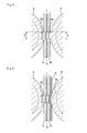
- FIGS. 1(a) and 1(b) are explanatory diagrams showing basis steps of a shearing method according to a first embodiment of the present invention.
- a workpiece plate 1 is an electrode plate for a lithium-ion battery, which is prepared by laminating two active material layers (non-metal layers) 1b on respective ones of opposite surfaces of a metal layer 1a made of copper or aluminum.
- the metal layer 1a has a thickness of 20 ⁇ m
- each of the non-metal layers 1b has a thickness of 80 ⁇ m.
- a thickness of the workpiece plate 1 is 180 ⁇ m in total.
- the workpiece plate 1 is placed on and fixed to a die 2 having a shearing hole 2a. Then, as shown in FIG. 1(b) , a punch 3 disposed just above the shearing hole 2a is moved downwardly to shear the workpiece plate 1.
- the punch 3 is stopped at a position away from an initial contact position between the punch 3 and an upper surface of the workpiece plate 1 by 30 ⁇ m, i.e. at a timing when the punch 3 is moved downwardly (in a depthwise direction of the workpiece plate 1) to a position corresponding to a depth equal to 17% of the thickness of the workpiece plate 1.
- a clearance between the punch and the die is set to 10 ⁇ m. The clearance of 10 ⁇ m is a value free of particular difficulty in fabricating a forming tool.
- the workpiece plate 1 is sheared without bringing the punch 3 into direct contact with the metal layer 1a located in a central region of the workpiece plate 1, so that it becomes possible to prevent a metal component of the metal layer 1a from adhering to the punch 3 and exerting adverse effects on the shearing.
- a problem of roughening of a sheared surface never occurs.
- FIG. 1 shows one example where the workpiece plate 1 is sheared which is prepared by laminating the two non-metal layers 1b on respective ones of the opposite surfaces of the metal layer 1b
- shear a workpiece plate prepared by laminating one non-metal layer on one of opposite surfaces of a metal layer in the same manner.
- the workpiece plate is placed such that the non-metal layer is located on an upper side thereof so as to allow the punch to be brought into contact with the non-metal layer.
- the punch 3 is disposed just above the die 2.
- the punch and the die are disposed upside down, i.e., the punch is disposed just below the die.
- the punch 3 is adapted to be moved vertically.
- the die 2 may be adapted to be moved vertically.
- FIG. 2 illustrates a shearing method according to a second embodiment of the present invention.
- the second embodiment is one example where a plurality of workpiece plates are stacked on each other to form a workpiece plate stack, and then sheared.
- each of eight workpiece plates 1 is an electrode plate for a lithium-ion battery, which has a thickness of 180 ⁇ m, as with the first embodiment, and they are stacked on each other vertically.
- a total thickness of the stacked workpiece plates 1, i.e., workpiece plate stack, is 1.44 mm.
- the punch 3 is stopped at a position away from an initial contact position between the punch 3 and an upper surface of the workpiece plate stack (eight stacked workpiece plates 1) by 200 ⁇ m, i.e. at a timing when the punch 3 is moved downwardly (in a depthwise direction of the workpiece plate stack) to a position corresponding to a depth equal to 14% of the thickness of the workpiece plate stack.
- FIG. 3 illustrates a shearing method according to a third embodiment of the present invention.
- the third embodiment is one example where a thin plate made of a metal is sheared using a punch and a die.
- a thin plate made of a metal is placed on a die 2, and then an intermediate plate 8 having at least one non-metal layer is placed on the workpiece plate 7.
- the workpiece plate 7 is comprised of a titanium plate having a thickness of 20 ⁇ m
- the intermediate plate 8 is comprised of a polypropylene plate having a thickness of 150 ⁇ m.
- a non-metal layer may be used which is made of one selected from the group consisting of acrylic resin, PET, polycarbonate, bakelite, plastic, fluororesin, epoxy resin, polyurethane, polyvinyl chloride, polyamide, polyethylene, vinyl chloride, hard rubber, paper, glass plate, asphalt and synthetic fiber, as well as polypropylene.
- a laminated material comprised of two or more of the non-metal layers or a laminated material comprised of the non-metal layer and a metal layer may be used.
- the punch 3 is stopped at a position away from an initial contact position between the punch 3 and an upper surface of the intermediate plate 8 by 40 ⁇ m, i.e. at a timing when the punch 3 is moved downwardly (in a depthwise direction of the intermediate plate 8 and the workpiece plate 7) to a position corresponding to a depth which is equal to or greater than the thickness of the workpiece plate 7 (the thin plate made of a metal) and equal to or less than the thickness of the intermediate plate 8, and until before the punch 3 penetrates through the intermediate plate 8.
- the workpiece plate 7 is fully sheared.
- a sheared product portion of the workpiece plate can be easily extracted by pushing or sucking it from thereabove or therebelow.
- a thrust depth after the punch 3 is initially brought into contact with the upper surface of the intermediate plate 8 is set to a value equal to or greater than the thickness of the workpiece plate (thin plate made of a metal) and equal to or less than the thickness of the intermediate plate 8.
- a prerequisite in this case is that the thickness of the intermediate plate is greater that the thickness of the workpiece plate (thin plate made of a metal).
- FIG. 4 illustrates a shearing method according to a fourth embodiment of the present invention.
- the fourth embodiment is one example where the present invention is applied to a shearing method using a die cut roll consisting of a die cutter and an anvil roll.
- a workpiece plate 1 in the fourth embodiment is the same as that in the first embodiment.
- a die cutter 4 has a convex push-cutting blade 4a provided on a surface thereof at a position corresponding to a shearing recess 5a of an anvil roll 5.
- the workpiece plate 1 is inserted between the die cutter 4 and the anvil roll 5 which are rotating in respective ones of the arrowed directions, and the convex push-cutting blade 4a of the die cutter is rotated and pressed toward the shearing recess 5a of the anvil roll 5 to shear the workpiece plate 1.
- the workpiece plate 1 is sheared without causing the convex push-cutting blade 4a of the die cutter to penetrate through the workpiece plate 1 and become fitted into the shearing recess 5a of the anvil roll, as shown in FIG. 4 .
- the convex push-cutting blade 4a is thrust to a position where a distal end thereof is located away from an upper surface of the workpiece plate 1 by 20 ⁇ m, i.e., a position corresponding to a depth equal to 11% of the thickness of the workpiece plate 1.
- a sheared product portion of the workpiece plate can be easily extracted by pushing or sucking it from thereabove or therebelow.
- a workpiece plate stack formed by stacking two workpiece plates 1 on each other is inserted between the die cutter 4 and the anvil roll 5, and the convex push-cutting blade 4a is thrust to a position corresponding to a depth equal to 36% of a thickness of the workpiece plate stack (two stacked workpiece plates 1).
- the convex push-cutting blade 4a is thrust to a position corresponding to a depth equal to 36% of a thickness of the workpiece plate stack (two stacked workpiece plates 1).
- the fourth embodiment illustrated in FIG. 4 shows one example where the workpiece plate 1 is sheared which is prepared by laminating the two non-metal layers 1b on respective ones of the opposite surfaces of the metal layer 1b, it is also possible to shear a workpiece plate prepared by laminating one non-metal layer on one of opposite surfaces of a metal layer, in the same manner.
- the workpiece plate is inserted to allow the non-metal layer to come into contact with the die cutter 4.
- FIG. 5 illustrates one modification of the fourth embodiment in FIG. 4 .
- an intermediate plate 6 having at least one non-metal layer is inserted between the die cutter 4 and the workpiece plate 1. Based on interposing the intermediate plate 6 in this manner, the workpiece plate 1 can be more reliably sheared by a pressing effect arising from plastic flow of the intermediate plate 6.
- a non-metal layer may be used which is made of one selected from the group consisting of acrylic resin, PET, polycarbonate, bakelite, plastic, fluororesin, epoxy resin, polyurethane, polyvinyl chloride, polyamide, polyethylene, polypropylene, vinyl chloride, hard rubber, paper, glass plate, asphalt and synthetic fiber.
- a laminated material comprised of two or more of the non-metal layers or a laminated material comprised of the non-metal layer and a metal layer may be used.
- FIG. 6 illustrates a shearing method according to a fifth embodiment of the present invention.
- the fifth embodiment is one example where a thin plate made of a metal is sheared using a die cutter and an anvil roll.
- a die cutter 4 has a convex push-cutting blade 4a provided on a surface thereof at a position corresponding to a shearing recess 5a of an anvil roll 5.
- a thin plate made of a metal as a workpiece plate 7 is inserted between the die cutter 4 and the anvil roll 5 which are rotating in respective ones of the arrowed directions, and an intermediate plate 6 having at least one non-metal layer is inserted between the die cutter 4 and the workpiece plate 7. Then, the convex push-cutting blade 4a of the die cutter is rotated so as to press the workpiece plate 7 toward the shearing recess 5a of the anvil roll 5 through the intermediate plate 6 to shear the workpiece plate 7.
- the workpiece plate 7 is sheared without causing the convex push-cutting blade 4a of the die cutter to penetrate through the intermediate plate 6 and the workpiece plate 7 and become fitted into the shearing recess 5a of the anvil roll.
- a distance (gap) between the die cutter 4 and the anvil roll 5 based on the same criteria as that in the third embodiment, in such a manner that a thrust depth of the workpiece plate (thin plate made of a metal) and the intermediate plate into the shearing recess 5a of the anvil roll becomes equal to or greater than a thickness of the workpiece plate and equal to or less than a thickness of the intermediate plate.
- the distance (gap) between the die cutter 4 and the anvil roll 5 is set to a value equal to or less than [(the thickness of the workpiece plate + the thickness of the intermediate plate) - the thickness of the workpiece plate] and equal to or greater than the thickness of the workpiece plate.
- the thickness of the intermediate plate is greater that the thickness of the workpiece plate (thin plate made of a metal).
- an outer peripheral shape of the convex push-cutting blade 4a of the die cutter is set to be equal to or slightly greater than an inner peripheral shape of the shearing recess 5a of the anvil roll.
- A is a length of one of four sides of the outer peripheral shape of the convex push-cutting blade 4a
- B is a length of a corresponding one of four sides of the inner peripheral shape of the shearing recess 5a.
- A is less than B, burrs are likely to occur in a sheared portion, which causes deterioration in quality of a sheared surface.
- A is greater than 1.1 B, a pressing portion, i.e., an area pressing the workpiece plate, becomes excessively widened, which causes deterioration in quality of the workpiece plate.
- the convex push-cutting blade 4a of the die cutter for use in the present invention will be described below.
- the convex push-cutting blade 4a of the die cutter is typically formed such that only an outer peripheral portion thereof protrudes outwardly to have an acute distal end.
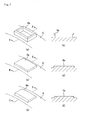
- the convex push-cutting blade 4a is not necessarily formed in a protruding shape with an acute distal end as shown in FIGS. 7(a) and 7(b) , because it is based on shearing.
- the convex push-cutting blade 4a may be formed to protrude in its entirety to have a right-angled edge as shown in FIGS. 7(c) and 7(d) , or may be formed to protrude in its entirety to have an obtuse-angled edge s shown in FIGS. 7(e) and 7(f) . Further, the edge may be rounded as indicated by the broken lines in FIGS. 7(d) and 7(f) .
- FIG. 8 illustrates a shearing method according to a sixth embodiment of the present invention.
- the sixth embodiment is one example where a workpiece plate is sheared using a press roll and an anvil roll.
- a workpiece plate 1 in the sixth embodiment is the same as that in the first embodiment.
- a press roll 9 has a smooth surface devoid of the convex push-cutting blade.
- An anvil roll 5 disposed opposed to the press roll 9 has a shearing recess 5a provided in a surface thereof in conformity to a shape of a product to be cut off.
- the workpiece plate 1 is inserted between the press roll 9 and the anvil roll 5 which are rotating in respective ones of the arrowed directions, and an intermediate plate 6 having at least one non-metal layer is inserted between the press roll 9 and the workpiece plate 1.
- the press roll 9 is rotated so as to press the workpiece plate 1 toward the shearing recess 5a of the anvil roll to shear the workpiece plate 1.
- the workpiece plate 1 is sheared without pressing the workpiece plate 1 into the shearing recess 5a of the anvil roll beyond a thickness of the workpiece plate 1.
- the workpiece plate 1 is pressed to a position corresponding to a depth in the shearing recess 5a of the anvil roll which is equal to or greater than a thickness of a metal layer 1a and equal to or less than a total thickness of one or more non-metal layers 1b of the workpiece plate 1.
- the workpiece plate 1 was actually pressed into the shearing recess 5a of the anvil roll by a depth of 20 ⁇ m. As a result, it was verified that the workpiece plate 1 is fully sheared.
- a workpiece plate stack formed by stacking two workpiece plates 1 on each other is inserted between the press roll 9 and the anvil roll 5, and pressed into the shearing recess 5a of the anvil roll by a depth of 80 ⁇ m. As a result, it was verified that both of the two workpiece plates 1 are fully sheared.
- FIG. 9 illustrates one modification of the sixth embodiment in FIG. 8 .
- a thin plate made of a metal is sheared as a workpiece plate 7.
- the press roll 9 is rotated so as to press the workpiece plate 7 into the shearing recess 5a of the anvil roll through an intermediate plate 6 to shear the workpiece plate 7.
- the workpiece plate is comprised of an aluminum foil having a thickness of 20 ⁇ m
- the intermediate plate 6 is comprised of a PET resin having a thickness of 500 ⁇ m.
- a distance (gap) between the press roll 9 and the anvil roll 5 is set to 500 ⁇ m.
- FIG. 10 illustrates a shearing method according to a seventh embodiment of the present invention.
- the intermediate plate 6 to be inserted between the workpiece plate 1 (7) and the die cutter 4 or press roll 9 is formed as a disposable type.
- an intermediate plate 6 in the seventh embodiment is formed as a repeatedly usable type.
- the intermediate plate 6 is formed in an endless configuration.
- the intermediate plate 6 is inserted between a die cutter 4 and a workpiece plate 1 (7) so as to be used for shearing to and then passed between a pair of rolls 10, 10, whereafter the intermediate plate 6 is re-inserted between the die cutter 4 and the workpiece plate 1 (7).
- a flexible material such as a rubber is used as a material for the intermediate plate 6 to allow the intermediate plate 6 to be easily returned to the original shape.
- a press roll may be used instead of the die cutter 4.
- FIG. 11 illustrates a shearing method according to an eighth embodiment of the present invention.
- the eighth embodiment is one example where a surface of a press roll 9 is coated with an outer layer 9a including at least one non-metal layer, instead of inserting an intermediate layer between the press roll 9 and a workpiece plate 1 (7).
- the shearing method according to the eighth embodiment is capable of performing shearing in the same manner as that in the shearing method designed to insert the intermediate plate between the press roll 9 and the workpiece plate 1 (7), and avoiding using the intermediate plate in a throwaway manner.
- the workpiece plate 1 (7) is sheared without pressing the workpiece plate 1 (7) into a shearing recess 5a of an anvil roll beyond a thickness of the workpiece plate 1(7).
- the outer layer 9a is made of a flexible material such a rubber to allow the outer layer 9a to be easily returned to its original shape.
- FIG. 12 illustrates a shearing method according to a ninth embodiment of the present invention.
- at least two cutouts 5b are provided at respective positions before and after a shearing recess 5a of an anvil roll 5 in a rotation direction thereof, with a given distance from the shearing recess 5a.
- an outer peripheral portion of the anvil roll 5 having a length L between a shearing recess 5a of the anvil roll and each of the cutouts 5a is a region required for the shearing of the workpiece plate 1 (7).
- the cutouts 5b are provided while leaving the regions, so that it becomes possible to prevent the workpiece plate 1(7) from being pressed between the die cutter 4 and the portion of the anvil roll 5 unnecessary for the shearing, while allowing for the shearing of the workpiece plate 1(7).
- the ninth embodiment is effective in such a workpiece plate.
- the length L in the range of 0.5 to 2 mm. If the length L is less than 0.5 mm, the anvil roll is likely to damage a surface region of the workpiece plate around a sheared surface. If the length L is greater than 2 mm, a pressing portion, i.e., an area pressing the workpiece plate, becomes excessively widened, which accelerates damage of the workpiece plate. Thus, it is most preferable to set the length L in the range of 0.5 to 2 mm, in view of preventing damage of a surface of the workpiece plate and minimizing the pressing portion.
- the ninth embodiment in FIG. 12 shows one example using the die cutter 4, it is understood that a press roll may be used instead of the die cutter 4.
- a peripheral edge region of a shearing recess of the anvil roll is made of a material having hardness greater than that of the remaining region of the anvil roll.
- the peripheral edge region of the shearing recess may be made of hard metal, ceramics or DCL coating. This makes it possible to prevent chipping or the like in the peripheral edge portion of the shearing recess which is a shearing area.
- each of the die cutter, the press roll and a body of the anvil roll is made of a material having a capability to facilitate ensuring machining accuracy, and a Young's modulus of 150 GPa or more.
Landscapes
- Engineering & Computer Science (AREA)
- Mechanical Engineering (AREA)
- Life Sciences & Earth Sciences (AREA)
- Forests & Forestry (AREA)
- Punching Or Piercing (AREA)
- Perforating, Stamping-Out Or Severing By Means Other Than Cutting (AREA)
Description
- The present invention relates to a method of shearing a thin plate, and more specifically to a method for forming a product by shearing a thin plate with a thickness of about 0.5 mm or less, which is made of a metal or prepared by laminating one or more non-metal layers on one or respective ones of opposite surfaces of a metal layer.
- As a technique for forming a product from a thin plate, a method of punching (blanking) a thin plate using a forming tool (punch and die) is most common.
- In the punching (blanking) method, the workpiece plate is subjected to shearing by placing a workpiece plate on a die having a punch hole, and moving a punch disposed just above the punch hole downwardly to allow a distal end of the punch to be fitted into the punch hole. In some cases, the punch and the die are disposed upside down, i.e., the punch is disposed just below the die, and the die is moved instead of the punch.
- In regard to conditions for the punching, considerable researches have heretofore been made. For example, the following Non-Patent
Document 1 discloses an adequate relationship between a thickness of a workpiece plate, and a gap between a punch and a die (punch hole) for punching the workpiece plate (the gap will hereinafter be referred to simply as "clearance"). In theNon-Patent Document 1, an adequate clearance is described as about 5 to 10% of the thickness of the workpiece plate. - According to this relationship between the thickness of the workpiece plate and the clearance, when the workpiece plate has a thickness of 1 mm, the clearance is in the range of about 50 to 100 µm. As long as the clearance is such a value, it is easy to fabricate a forming tool, etc. However, when the workpiece plate has a smaller thickness, e.g., a thickness of 20 µm, the adequate clearance is reduced to 1 to 2 µm, so that a high level of fabrication technique, such as precision machining, is required for a forming tool, which leads to a problem of an increase in cost.
- Moreover, a punching operation using a forming tool fabricated to have a narrowed clearance involves other problems. One problem is a reduction in usable life of the forming tool due to wear of the punch and the die. Specifically, a narrower clearance leads to a higher frequency of contact between the punch and the die in elastic deformation ranges thereof, which accelerates wear thereof. Further, if the punch and the die are deformed beyond the elastic deformation ranges during the contact therebetween, a problem of chipping will also occur.
- Another major problem is a problem with debris to be generated from a workpiece plate during punching. This problem becomes prominent when the workpiece plate is a laminated plate comprised of a metal layer and a non-metal layer. Debris generated from a workpiece plate is trapped between the punch and the die, which causes various problems, such as a problem of an increase in force required for punching, and a problem of an increase in frequency of cleaning required for the punch and the die. Moreover, the debris is likely to cause breakage of the forming tool.
- The conventional punching method has another problem. Specifically, along with punching of a workpiece plate, particularly a metal plate, depending on its compatibility with a forming tool, adhesion of the workpiece plate is likely to occur in a punch. It is possible to prevent the adhesion problem to some extent by coating a punch and a die with ceramics, DLC (Diamond-Like Carbon) or the like. However, in a forming tool having a narrow clearance, only a temporary effect can be obtained because large wear occurs in a punch and a die due to a sliding movement therebetween.
- Still another problem is deterioration in quality of an outer edge of a punched-out portion of the workpiece plate (product portion). This is because, after punching the workpiece plate, the punched-out portion is moved to a dead center position of the punch while rubbing against an inner surface of the die, i.e., placed in a rubbing state through until it is separated from the die.
- As above, in shearing based on the conventional punching method, various problems occurs, particularly, when a workpiece plate has a small thickness.
- Non-Patent Document 1: A. Hashimoto, "Press Operations & Die Machining Methods New Edition", 7th Edition, Nikkan Kogyo Shimbun, Ltd., April 30, 1975, p 35
- In view of the above various problems involved in shearing based on the conventional punching method, it is an object of the present invention to provide a method capable of shearing a thin plate with high quality over a long period of time, and significantly excellently shearing a thin plate based on a low-cost forming tool and a low-cost process, without the necessity to subject a forming tool for use in the shearing to precision machining.
- Through various researches on shearing of thin plates, the inventor found that, in a thin plate prepared by laminating one or more non-metal layers on one or respective ones of opposite surfaces of a metal layer, the thin plate is fully sheared before a punch penetrates through the thin plate and becomes fitted into a shearing hole of a die.
- The present invention has been made based on the above finding. Specifically, the present invention provides a method of shearing a thin plate prepared by laminating one or more non-metal layers on one or respective ones of opposite surfaces of a metal layer. The method comprises: placing the thin plate between a punch and a die having a shearing hole; and relatively moving the punch toward and with respect to the shearing hole to thereby shear the thin plate, wherein the relative movement of the punch is stopped to complete the shearing, before the punch penetrates through the thin plate and becomes fitted into the shearing hole.
- As above, in the present invention, the punch is not fitted into the die, so that it is not necessary to severely adjust a clearance as in the conventional punching method designed to allow the punch to be fitted into the die. Thus, the clearance may be set to a zero clearance, or a minus clearance in which an outer diameter of the punch is set to be greater than an inner diameter of the die, as well as an usual plus clearance. In other words, in the present invention, it is not necessary to severely adjust a clearance based on precision machining of a forming tool (punch and die), so that it becomes possible to easily fabricate the forming tool and reduce a fabrication cost of the forming tool.
- In addition, based on the feature that the punch is not fitted into the die, each of the punch and the die becomes less likely to be worn, which provides extended usable life of the forming tool. Further, a displacement of a sheared portion of a workpiece plate is reduced, and thereby an amount of debris to be generated is reduced. The conventional method also has a problem that, along with a vertical movement of the punch, a metal portion of a workpiece plate in contact with the punch adheres to the punch. It is difficult to remove the adhered metal component. If it is tried to remove the adhered metal component by rubbing or scraping, or using chemicals, a surface of the punch will have scars, or higher roughness, or alteration due to corrosion. Moreover, the adhesion phenomenon occurs after 100 shots at the latest, or after only 5 to 10 shots at the earliest. In contrast, in the method of the present invention, the shearing can be performed without bringing the punch into direct contact with a metal portion of a workpiece plate, so that it becomes possible to prevent the workpiece plate from adhering to the punch.
- Thus, a shearing state can be excellently maintained, and the thin plate can be sheared with high quality. As for a forming tool, there is no need to fabricate a forming tool with a maximally narrowed clearance which causes difficulty in fabrication and leads to a high cost, and therefore there is no need to take a high cost for fabrication of a forming tool.
- Meanwhile, in the technical field of punching (blanking), there has been known a method of punching a workpiece plate by subjecting the workpiece plate to half blanking in one direction, and then subjecting the workpiece plate to reversed blanking, instead of punching the workpiece plate by a single punching operation (see, for example,
JP 2004-167547A JP 2001-300647A - Preferably, in the present invention, the punch is stopped at a position corresponding to a depth in the thin plate which is equal to or greater than a thickness of the metal layer and equal to or less than a total thickness of the one or more non-metal layers. If the depth corresponding to the stop position of the punch is less than the thickness of the metal layer, a possibility to fail to complete the shearing of the thin plate will be increased. Further, if the depth is greater than the total thickness of the one or more non-metal layers, chipping in the punch and the die, an increase in amount of debris and/or adhesion of a metal component of the thin plate to the punch will occur, which is likely to cause difficulty in sufficiently obtain the effects of the present invention.
- Through experimental tests conducted by the inventor, it has been found that the shearing method of the present invention can also be applied to a thin plate stack formed by stacking a plurality of the thin plates on each other. In this case, the thin plate stack is placed between the punch and the die, and the relative movement of the punch is stopped to complete the shearing, before the punch penetrates through the thin plate stack and becomes fitted into the shearing hole. In this manner, the plurality of thin plates can be simultaneously sheared to provide enhanced productivity. In cases where a plurality of thin plates are originally used in the form of a laminated structure as in an electrode plate for a lithium-ion battery, etc., a step of laminating respective sheared portions of the thin plates can be omitted by simultaneously shearing the laminated thin plates. However, the number of the thin plates capable of being simultaneously sheared is about 10 at a maximum, in view of quality of a cut (sheared) surface of a workpiece plate. If the number is excessively increased, the cut surface will be gradually roughened, so that it becomes difficult to use resulting products in the field requiring high quality. Preferably, in cases where a thin plate stack formed by stacking a plurality of the thin plates on each other is simultaneously sheared, the punch is stopped at a position corresponding a depth in the thin plate stack which is equal to or greater than a total thickness of the metal layers of the thin plate stack (a sum of respective thicknesses of the metal layers in the plurality of staked thin plates) and equal to or less than a total thickness of the non-metal layers of the thin plate stack (a sum of respective thicknesses of the non-metal layers in the plurality of staked thin plates).
- In addition to the shearing using the punch and the die, the shearing method of the present invention can also be applied to shearing using a die cutter and an anvil roll. Specifically, the present invention provides a method of shearing a thin plate prepared by laminating one or more non-metal layers on one or respective ones of opposite surfaces of a metal layer. The method comprises: inserting the thin plate between a die cutter provided with a convex push-cutting blade on a surface thereof, and an anvil roll provided with a shearing recess at a position corresponding to the convex push-cutting blade; and rotating and pressing the convex push-cutting blade of the die cutter toward the shearing recess of the anvil roll to thereby shear the thin plate, wherein the thin plate is sheared without causing the convex push-cutting blade of the die cutter to penetrate through the thin plate and become fitted into the shearing recess of the anvil roll. This shearing method also provides the same effects as those of the shearing using the punch and the die. In other words, the thin plate is fully sheared before the convex push-cutting blade of the die cutter penetrates through the thin plate and become fitted into the shearing recess of the anvil roll.
- Preferably, in the shearing method using the die cutter and the anvil roll, the convex push-cutting blade of the die cutter is thrust to a position corresponding to a depth in the thin plate which is equal to or greater than the thickness of the metal layer and equal to or less than the total thickness of the one or more non-metal layers.
- Further, in order to more reliably shear the thin plate (i.e., workpiece plate) in the shearing method using the die cutter and the anvil roll, an intermediate plate having at least one non-metal layer may be inserted between the die cutter and the thin plate. Based on using the intermediate plate in the above manner, the thin plate can be more reliably sheared by a pressing effect arising from plastic flow of the intermediate plate. Preferably, in this case, the convex push-cutting blade of the die cutter is thrust to a position corresponding to a depth in a combination of the intermediate plate and the thin plate which is equal to or greater than a total thickness of the metal layers of the thin plate and equal to or less than a total thickness of the one or more non-metal layers of the thin plate and the intermediate plate.
- In the present invention, in place of the die cutter provided with the convex push-cutting blade on a surface thereof, a press roll devoid of the convex push-cutting blade may be used. Specifically, the present invention provides a method of shearing a thin plate prepared by laminating one or more non-metal layers on one or respective ones of opposite surfaces of a metal layer. The method comprises: inserting the thin plate between a press roll, and an anvil roll provided with a shearing recess; and rotating the press roll to press the thin plate toward the shearing recess of the anvil roll to thereby shear the thin plate, wherein an intermediate plate having at least one non-metal layer is inserted between the thin plate and the die cutter, and the thin plate is sheared without pressing the thin plate into the shearing recess of the anvil roll beyond a thickness of the thin plate. In this shearing method, the thin plate is fully sheared before the thin plate is fully pressed into the shearing recess of the anvil roll. Preferably, in this shearing method, the thin plate is pressed to a position corresponding to a depth in the shearing recess of the anvil roll which is equal to or greater than a thickness of the metal layer and equal to or less than a total thickness of the one or more non-metal layers of the thin plate.
- The shearing method using the die cutter or press roll and the anvil roll, a thin plate stack formed by stacking a plurality of the thin plates on each other may be inserted between the die cutter or press roll and the anvil roll, to simultaneously shear the plurality of stacked thin plates. Specifically, in the shearing method using the die cutter and the anvil roll, the thin plate stack is inserted between the die cutter and the anvil roll, and all of the thin plates are sheared without causing the convex push-cutting blade of the die cutter to penetrate through the thin plate stack and become fitted into the shearing recess of the anvil roll. Preferably, in this case, the convex push-cutting blade of the die cutter is thrust to a position corresponding to a depth in the thin plate stack which is equal to or greater than a total thickness of the metal layers of the thin plate stack and equal to or less than a total thickness of the non-metal layers of the thin plate stack. When the intermediate plate is used in combination, it is preferable that the convex push-cutting blade of the die cutter is thrust to a position corresponding to a depth in a combination of the intermediate plate and the thin plate stack which is equal to or greater than a total thickness of the metal layers of the thin plate stack and equal to or less than a total thickness of the non-metal layers of the thin plate stack and the intermediate plate.
- On the other hand, in the shearing method using the press roll and the anvil roll, the thin plate stack is inserted between the press roll and the anvil roll, and the intermediate plate having at least one non-metal layer is inserted between the thin plate stack and the press roll, whereafter the thin plate stack is sheared without pressing the thin plate stack into the shearing recess of the anvil roll beyond a thickness of the thin plate stack. Preferably, in this case, the thin plate stack is pressed to a position corresponding to a depth in the shearing recess of the anvil roll which is equal to or greater than a total thickness of the metal layers of the thin plate stack and equal to or less than a total thickness of the non-metal layers of the thin plate stack.
- In the present invention, in the shearing method using the press roll and the anvil roll, a surface of the press roll may be coated with a layer including at least one non-metal layer. Specifically, the present invention provides a method of shearing a thin plate which is made of a metal or prepared by laminating one or more non-metal layers on one or respective ones of opposite surfaces of a metal layer. The method comprises: inserting the thin plate between a press roll having a surface coated with a layer including at least one non-metal layer, and an anvil roll provided with a shearing recess; and rotating the press roll to press the thin plate toward the shearing recess of the anvil roll to thereby shear the thin plate, wherein the thin plate is sheared without pressing the thin plate into the shearing recess of the anvil roll beyond a thickness of the thin plate. Preferably, in this shearing method, the thin plate is pressed to a position corresponding to a depth in the shearing recess of the anvil roll which is equal to or greater than a thickness of the metal layer and equal to or less than a total thickness of the one or more non-metal layers of the thin plate. In this shearing method, when a plurality of the thin plates are stacked on each other to form a thin plate stack, and the thin plate stack is inserted between the press roll and the anvil roll and sheared, the thin plate stack is sheared without pressing the thin plate stack into the shearing recess of the anvil roll beyond a thickness of the thin plate stack. Preferably, the thin plate stack is pressed to a position corresponding to a depth in the shearing recess of the anvil roll which is equal to or greater than a total thickness of the metal layers of the thin plate stack and equal to or less than a total thickness of the non-metal layers of the thin plate stack.
- As mentioned above, the shearing method of the present invention is applied to a thin plate prepared by laminating one or more non-metal layers on one or respective ones of opposite surfaces of a metal layer. However, the shearing method of the present invention may also be applied to a thin plate made of a metal. Specifically, in a shearing method using a punch and a die having a shearing hole, a thin plate made of a metal is placed between the punch and the die, and the punch is relatively moved toward and with respect to the shearing hole to thereby shear the thin plate, wherein an intermediate plate having at least one non-metal layer is placed between the thin plate and the punch, and the relative movement of the punch is stopped to complete the shearing of the metal plate, before the punch penetrates through the intermediate plate. Preferably, in this case, the relative movement of the punch is stopped at a position corresponding to a depth in a combination of the thin plate and the intermediate plate which is equal to or greater than a thickness of the thin plate and equal to or less than a thickness of the intermediate plate.
- In a shearing method using a die cutter provided with a convex push-cutting blade on a surface thereof and an anvil roll provided with a shearing recess at a position corresponding to the convex push-cutting blade, a thin plate made of a metal is inserted between the die cutter and the anvil roll, and the convex push-cutting blade of the die cutter is rotated and pressed toward the shearing recess of the anvil roll to thereby shear the thin plate, wherein an intermediate plate having at least one non-metal layer is inserted between the thin plate and the die cutter, and the thin plate is sheared without causing the convex push-cutting blade of the die cutter to penetrate through the intermediate plate and become fitted into the shearing recess of the anvil roll. Preferably, in this case, the convex push-cutting blade of the die cutter is thrust to a position corresponding to a depth in a combination of the thin plate and the intermediate plate which is equal to or greater than a thickness of the thin plate and equal to or less than a thickness of the intermediate plate.
- In a shearing method using a press roll and an anvil roll provided with a shearing recess, a thin plate made of a metal is inserted between the press roll and the anvil roll, and the press roll is rotated to press the thin plate toward the shearing recess of the anvil roll to thereby shear the thin plate, wherein an intermediate plate having at least one non-metal layer is inserted between the thin plate and the die cutter, and the thin plate is sheared without pressing the thin plate into the shearing recess of the anvil roll beyond a thickness of the thin plate. In a shearing method using a press roll having a surface coated with a layer including at least one non-metal layer, and an anvil roll provided with a shearing recess, a thin plate made of metal is inserted between the press roll and the anvil roll, and the press roll is rotated to press the thin plate toward the shearing recess of the anvil roll to thereby shear the thin plate, wherein the thin plate is sheared without pressing the thin plate into the shearing recess of the anvil roll beyond a thickness of the thin plate.
- Among the above shearing methods of the present invention, in the shearing method using the die cutter or press roll, the anvil roll and the intermediate plate, in order to allow the intermediate plate to be repeatedly used, the intermediate plate may be formed in an endless configuration, wherein the intermediate plate is inserted between the die cutter or press roll and the thin plate or thin plate stack and then passed and pressed between a pair of rolls, whereafter the intermediate plate is re-inserted between the die cutter or press roll and the thin plate or thin plate stack.
- In the present invention, the anvil roll may be formed such that the shearing recess thereof has a peripheral edge region made of a material having hardness greater than that of the remaining region of the anvil roll. This makes it possible to reliably perform the shearing while preventing chipping or the like from occurring in the peripheral edge region of the shearing recess which is a shearing area.
- Further, the anvil roll may have at least two cutouts provided at respective positions before and after the shearing recess in a rotation direction thereof, with a given distance from the shearing recess. This makes it possible to prevent the thin plate or thin plate stack from being excessively pressed at respective positions before and after the shearing recess and damaged.
- In a method of shearing a thin plate which is made of a metal or prepared by laminating one or more non-metal layers on one or respective ones of opposite surfaces of a metal layer, the present invention makes it possible to shear the thin plate with high quality over a long period of time while allowing a forming tool to be fabricated at relatively low cost, and therefore perform the shearing of the thin plate with high quality at low cost.
-
-
FIGS. 1(a) and 1(b) illustrate basic steps of a shearing method according to a first embodiment of the present invention. -
FIGS. 2(a) and 2(b) illustrate a shearing method according to a second embodiment of the present invention. -
FIGS. 3(a) and 3(b) illustrate a shearing method according to a third embodiment of the present invention. -
FIG. 4 illustrates a shearing method according to a fourth embodiment of the present invention. -
FIG. 5 illustrates one modification of the embodiment inFIG. 4 . -
FIG. 6 illustrates a shearing method according to a fifth embodiment of the present invention. -
FIGS. 7(a) to 7(f) illustrate various examples of a shape of a convex push-cutting blade of a die cutter, whereinFIG. 7(b), FIG. 7(d) and FIG. 7(f) are sectional views taken along the line A-A inFIG. 7(a) , the line B-B inFIG. 7(c) and the line C-C inFIG. 7(e) , respectively. -
FIG. 8 illustrates a shearing method according to a sixth embodiment of the present invention. -
FIG. 9 illustrates one modification of the embodiment inFIG. 8 . -
FIG. 10 illustrates a shearing method according to a seventh embodiment of the present invention. -
FIG. 11 illustrates a shearing method according to an eighth embodiment of the present invention. -
FIG. 12 illustrates a shearing method according to a ninth embodiment of the present invention. - With reference to the drawings, the present invention will now be described based on various embodiments thereof.
-
FIGS. 1(a) and 1(b) are explanatory diagrams showing basis steps of a shearing method according to a first embodiment of the present invention.
In the first embodiment illustrated inFIG. 1 , aworkpiece plate 1 is an electrode plate for a lithium-ion battery, which is prepared by laminating two active material layers (non-metal layers) 1b on respective ones of opposite surfaces of ametal layer 1a made of copper or aluminum. Themetal layer 1a has a thickness of 20 µm, and each of thenon-metal layers 1b has a thickness of 80 µm. Thus, a thickness of theworkpiece plate 1 is 180 µm in total. - As shown in
FIG. 1(a) , theworkpiece plate 1 is placed on and fixed to adie 2 having ashearing hole 2a. Then, as shown inFIG. 1(b) , apunch 3 disposed just above theshearing hole 2a is moved downwardly to shear theworkpiece plate 1. - In the first embodiment, the
punch 3 is stopped at a position away from an initial contact position between thepunch 3 and an upper surface of theworkpiece plate 1 by 30 µm, i.e. at a timing when thepunch 3 is moved downwardly (in a depthwise direction of the workpiece plate 1) to a position corresponding to a depth equal to 17% of the thickness of theworkpiece plate 1. In a test carried out under the above conditions, it was verified that theworkpiece plate 1 is fully sheared. A sheared product portion of theworkpiece plate 1 can be easily extracted by pushing or sucking it from thereabove or therebelow. In the first embodiment, a clearance between the punch and the die is set to 10 µm. The clearance of 10 µm is a value free of particular difficulty in fabricating a forming tool. - As above, in the first embodiment, the
workpiece plate 1 is sheared without bringing thepunch 3 into direct contact with themetal layer 1a located in a central region of theworkpiece plate 1, so that it becomes possible to prevent a metal component of themetal layer 1a from adhering to thepunch 3 and exerting adverse effects on the shearing. In addition, a problem of roughening of a sheared surface never occurs. - Although the first embodiment illustrated in
FIG. 1 shows one example where theworkpiece plate 1 is sheared which is prepared by laminating the twonon-metal layers 1b on respective ones of the opposite surfaces of themetal layer 1b, it is also possible to shear a workpiece plate prepared by laminating one non-metal layer on one of opposite surfaces of a metal layer, in the same manner. Preferably, in this case, the workpiece plate is placed such that the non-metal layer is located on an upper side thereof so as to allow the punch to be brought into contact with the non-metal layer. - In the first embodiment illustrated in
FIG. 1 , thepunch 3 is disposed just above thedie 2. Alternatively, the punch and the die are disposed upside down, i.e., the punch is disposed just below the die. In the first embodiment illustrated in FIG. 1, thepunch 3 is adapted to be moved vertically. Alternatively, thedie 2 may be adapted to be moved vertically. -
FIG. 2 illustrates a shearing method according to a second embodiment of the present invention. The second embodiment is one example where a plurality of workpiece plates are stacked on each other to form a workpiece plate stack, and then sheared. - In the second embodiment, each of eight
workpiece plates 1 is an electrode plate for a lithium-ion battery, which has a thickness of 180 µm, as with the first embodiment, and they are stacked on each other vertically. Thus, a total thickness of the stackedworkpiece plates 1, i.e., workpiece plate stack, is 1.44 mm. - In the second embodiment, the
punch 3 is stopped at a position away from an initial contact position between thepunch 3 and an upper surface of the workpiece plate stack (eight stacked workpiece plates 1) by 200 µm, i.e. at a timing when thepunch 3 is moved downwardly (in a depthwise direction of the workpiece plate stack) to a position corresponding to a depth equal to 14% of the thickness of the workpiece plate stack. In a test carried out under the above conditions, it was verified that all of the eightworkpiece plates 1 are fully sheared. -
FIG. 3 illustrates a shearing method according to a third embodiment of the present invention. The third embodiment is one example where a thin plate made of a metal is sheared using a punch and a die. - As shown in
FIG. 3(a) , a thin plate made of a metal, as aworkpiece plate 7, is placed on adie 2, and then anintermediate plate 8 having at least one non-metal layer is placed on theworkpiece plate 7. In the third embodiment, theworkpiece plate 7 is comprised of a titanium plate having a thickness of 20 µm, and theintermediate plate 8 is comprised of a polypropylene plate having a thickness of 150 µm. As a material of theintermediate plate 8, a non-metal layer may be used which is made of one selected from the group consisting of acrylic resin, PET, polycarbonate, bakelite, plastic, fluororesin, epoxy resin, polyurethane, polyvinyl chloride, polyamide, polyethylene, vinyl chloride, hard rubber, paper, glass plate, asphalt and synthetic fiber, as well as polypropylene. Further, a laminated material comprised of two or more of the non-metal layers or a laminated material comprised of the non-metal layer and a metal layer may be used. - Then, as shown in
FIG. 3(b) , apunch 3 disposed just above ashearing hole 2a of the die is moved downwardly to shear theworkpiece plate 7. - In the third embodiment, the
punch 3 is stopped at a position away from an initial contact position between thepunch 3 and an upper surface of theintermediate plate 8 by 40 µm, i.e. at a timing when thepunch 3 is moved downwardly (in a depthwise direction of theintermediate plate 8 and the workpiece plate 7) to a position corresponding to a depth which is equal to or greater than the thickness of the workpiece plate 7 (the thin plate made of a metal) and equal to or less than the thickness of theintermediate plate 8, and until before thepunch 3 penetrates through theintermediate plate 8. In a test carried out under the above conditions, it was verified that theworkpiece plate 7 is fully sheared. A sheared product portion of the workpiece plate can be easily extracted by pushing or sucking it from thereabove or therebelow. - In the method designed to shear a thin plate made of a metal, through the
intermediate plate 8, as in the third embodiment, it is preferable to stop thepunch 3 before thepunch 3 is moved by a distance equal to the thickness of the thin plate, as the earliest timing, or before thepunch 3 penetrates theintermediate plate 8, as the latest timing, after thepunch 3 is initially brought into contact with the upper surface of theintermediate plate 8. In other words, it is preferable that a thrust depth after thepunch 3 is initially brought into contact with the upper surface of theintermediate plate 8, is set to a value equal to or greater than the thickness of the workpiece plate (thin plate made of a metal) and equal to or less than the thickness of theintermediate plate 8. A prerequisite in this case is that the thickness of the intermediate plate is greater that the thickness of the workpiece plate (thin plate made of a metal). -
FIG. 4 illustrates a shearing method according to a fourth embodiment of the present invention. The fourth embodiment is one example where the present invention is applied to a shearing method using a die cut roll consisting of a die cutter and an anvil roll. Aworkpiece plate 1 in the fourth embodiment is the same as that in the first embodiment. - As shown in
FIG. 4 , adie cutter 4 has a convex push-cutting blade 4a provided on a surface thereof at a position corresponding to ashearing recess 5a of ananvil roll 5. Theworkpiece plate 1 is inserted between thedie cutter 4 and theanvil roll 5 which are rotating in respective ones of the arrowed directions, and the convex push-cutting blade 4a of the die cutter is rotated and pressed toward theshearing recess 5a of theanvil roll 5 to shear theworkpiece plate 1. - In the fourth embodiment, during the shearing operation, the
workpiece plate 1 is sheared without causing the convex push-cutting blade 4a of the die cutter to penetrate through theworkpiece plate 1 and become fitted into theshearing recess 5a of the anvil roll, as shown inFIG. 4 . In the fourth embodiment, the convex push-cutting blade 4a is thrust to a position where a distal end thereof is located away from an upper surface of theworkpiece plate 1 by 20 µm, i.e., a position corresponding to a depth equal to 11% of the thickness of theworkpiece plate 1. In a test carried out under the above conditions, it was verified that theworkpiece plate 1 is fully sheared in the same manner as that in the first embodiment. A sheared product portion of the workpiece plate can be easily extracted by pushing or sucking it from thereabove or therebelow. - Although not illustrated, another test was carried out under the following conditions: A workpiece plate stack formed by stacking two
workpiece plates 1 on each other is inserted between thedie cutter 4 and theanvil roll 5, and the convex push-cutting blade 4a is thrust to a position corresponding to a depth equal to 36% of a thickness of the workpiece plate stack (two stacked workpiece plates 1). As a result, it was verified that all of the twoworkpiece plates 1 are fully sheared in the same manner as that in the second embodiment. - Although the fourth embodiment illustrated in
FIG. 4 shows one example where theworkpiece plate 1 is sheared which is prepared by laminating the twonon-metal layers 1b on respective ones of the opposite surfaces of themetal layer 1b, it is also possible to shear a workpiece plate prepared by laminating one non-metal layer on one of opposite surfaces of a metal layer, in the same manner. Preferably, in this case, the workpiece plate is inserted to allow the non-metal layer to come into contact with thedie cutter 4. -
FIG. 5 illustrates one modification of the fourth embodiment inFIG. 4 . In the modified embodiment illustrated inFIG. 5 , anintermediate plate 6 having at least one non-metal layer is inserted between thedie cutter 4 and theworkpiece plate 1. Based on interposing theintermediate plate 6 in this manner, theworkpiece plate 1 can be more reliably sheared by a pressing effect arising from plastic flow of theintermediate plate 6. - Specifically, as the
intermediate plate 8, a non-metal layer may be used which is made of one selected from the group consisting of acrylic resin, PET, polycarbonate, bakelite, plastic, fluororesin, epoxy resin, polyurethane, polyvinyl chloride, polyamide, polyethylene, polypropylene, vinyl chloride, hard rubber, paper, glass plate, asphalt and synthetic fiber. Further, a laminated material comprised of two or more of the non-metal layers or a laminated material comprised of the non-metal layer and a metal layer may be used. -
FIG. 6 illustrates a shearing method according to a fifth embodiment of the present invention. The fifth embodiment is one example where a thin plate made of a metal is sheared using a die cutter and an anvil roll. - As shown in
FIG. 6 , adie cutter 4 has a convex push-cutting blade 4a provided on a surface thereof at a position corresponding to ashearing recess 5a of ananvil roll 5. In the fifth embodiment, a thin plate made of a metal, as aworkpiece plate 7, is inserted between thedie cutter 4 and theanvil roll 5 which are rotating in respective ones of the arrowed directions, and anintermediate plate 6 having at least one non-metal layer is inserted between thedie cutter 4 and theworkpiece plate 7. Then, the convex push-cutting blade 4a of the die cutter is rotated so as to press theworkpiece plate 7 toward theshearing recess 5a of theanvil roll 5 through theintermediate plate 6 to shear theworkpiece plate 7. During the shearing operation, theworkpiece plate 7 is sheared without causing the convex push-cutting blade 4a of the die cutter to penetrate through theintermediate plate 6 and theworkpiece plate 7 and become fitted into theshearing recess 5a of the anvil roll. - In the method designed to shear the workpiece plate 7 (thin plate made of a metal) by the die cut roll through the
intermediate plate 8, as in the fifth embodiment, it is preferable to set a distance (gap) between thedie cutter 4 and theanvil roll 5, based on the same criteria as that in the third embodiment, in such a manner that a thrust depth of the workpiece plate (thin plate made of a metal) and the intermediate plate into theshearing recess 5a of the anvil roll becomes equal to or greater than a thickness of the workpiece plate and equal to or less than a thickness of the intermediate plate. In other words, it is preferable that the distance (gap) between thedie cutter 4 and theanvil roll 5 is set to a value equal to or less than [(the thickness of the workpiece plate + the thickness of the intermediate plate) - the thickness of the workpiece plate] and equal to or greater than the thickness of the workpiece plate. A prerequisite in this case is that the thickness of the intermediate plate is greater that the thickness of the workpiece plate (thin plate made of a metal). - According to experimental tests carried out by the inventor, in the fourth and fifth embodiments using the
die cutter 4 and theanvil roll 5, it is preferable that an outer peripheral shape of the convex push-cutting blade 4a of the die cutter is set to be equal to or slightly greater than an inner peripheral shape of theshearing recess 5a of the anvil roll. Specifically, as shown inFIG. 4 , it is preferable to satisfy the following relationship: B ≤ A ≤ 1.1 B, where A is a length of one of four sides of the outer peripheral shape of the convex push-cutting blade 4a, and B is a length of a corresponding one of four sides of the inner peripheral shape of theshearing recess 5a. The reason is that, if A is less than B, burrs are likely to occur in a sheared portion, which causes deterioration in quality of a sheared surface. On the other hand; if A is greater than 1.1 B, a pressing portion, i.e., an area pressing the workpiece plate, becomes excessively widened, which causes deterioration in quality of the workpiece plate. - A shape of the convex push-
cutting blade 4a of the die cutter for use in the present invention will be described below. In shearing using the die cutter, as shown inFIGS. 7(a) and 7(b) , the convex push-cutting blade 4a of the die cutter is typically formed such that only an outer peripheral portion thereof protrudes outwardly to have an acute distal end. In the present invention, the convex push-cutting blade 4a is not necessarily formed in a protruding shape with an acute distal end as shown inFIGS. 7(a) and 7(b) , because it is based on shearing. Thus, the convex push-cutting blade 4a may be formed to protrude in its entirety to have a right-angled edge as shown inFIGS. 7(c) and 7(d) , or may be formed to protrude in its entirety to have an obtuse-angled edge s shown inFIGS. 7(e) and 7(f) . Further, the edge may be rounded as indicated by the broken lines inFIGS. 7(d) and 7(f) . -
FIG. 8 illustrates a shearing method according to a sixth embodiment of the present invention. The sixth embodiment is one example where a workpiece plate is sheared using a press roll and an anvil roll. Aworkpiece plate 1 in the sixth embodiment is the same as that in the first embodiment. - As shown in
FIG. 8 , apress roll 9 has a smooth surface devoid of the convex push-cutting blade. Ananvil roll 5 disposed opposed to thepress roll 9 has ashearing recess 5a provided in a surface thereof in conformity to a shape of a product to be cut off. In the sixth embodiment, theworkpiece plate 1 is inserted between thepress roll 9 and theanvil roll 5 which are rotating in respective ones of the arrowed directions, and anintermediate plate 6 having at least one non-metal layer is inserted between thepress roll 9 and theworkpiece plate 1. - Then, the
press roll 9 is rotated so as to press theworkpiece plate 1 toward theshearing recess 5a of the anvil roll to shear theworkpiece plate 1. During the shearing operation, theworkpiece plate 1 is sheared without pressing theworkpiece plate 1 into theshearing recess 5a of the anvil roll beyond a thickness of theworkpiece plate 1. Specifically, theworkpiece plate 1 is pressed to a position corresponding to a depth in theshearing recess 5a of the anvil roll which is equal to or greater than a thickness of ametal layer 1a and equal to or less than a total thickness of one or morenon-metal layers 1b of theworkpiece plate 1. In a test, theworkpiece plate 1 was actually pressed into theshearing recess 5a of the anvil roll by a depth of 20 µm. As a result, it was verified that theworkpiece plate 1 is fully sheared. - Although not illustrated, another test was carried out under the following conditions: A workpiece plate stack formed by stacking two
workpiece plates 1 on each other is inserted between thepress roll 9 and theanvil roll 5, and pressed into theshearing recess 5a of the anvil roll by a depth of 80 µm. As a result, it was verified that both of the twoworkpiece plates 1 are fully sheared. -
FIG. 9 illustrates one modification of the sixth embodiment inFIG. 8 . In the modified embodiment illustrated inFIG. 9 , a thin plate made of a metal is sheared as aworkpiece plate 7. Specifically, thepress roll 9 is rotated so as to press theworkpiece plate 7 into theshearing recess 5a of the anvil roll through anintermediate plate 6 to shear theworkpiece plate 7. - More specifically, the workpiece plate is comprised of an aluminum foil having a thickness of 20 µm, and the
intermediate plate 6 is comprised of a PET resin having a thickness of 500 µm. Further, a distance (gap) between thepress roll 9 and theanvil roll 5 is set to 500 µm. In a test carried out under the above conditions, it was verified that theworkpiece plate 7 is fully sheared. -
FIG. 10 illustrates a shearing method according to a seventh embodiment of the present invention. In the embodiments illustrated inFIGS. 5 ,6 ,8 and9 , theintermediate plate 6 to be inserted between the workpiece plate 1 (7) and thedie cutter 4 orpress roll 9 is formed as a disposable type. Differently, anintermediate plate 6 in the seventh embodiment is formed as a repeatedly usable type. - Specifically, as shown in
FIG. 10 , theintermediate plate 6 is formed in an endless configuration. Theintermediate plate 6 is inserted between adie cutter 4 and a workpiece plate 1 (7) so as to be used for shearing to and then passed between a pair ofrolls intermediate plate 6 is re-inserted between thedie cutter 4 and the workpiece plate 1 (7). Thus, even if plastic deformation corresponding to ashearing recess 5a of the anvil roll (a convex push-cutting blade 4a of the die cutter) occurs in theintermediate plate 6 used for the shearing, due to the pressing during the shearing, theintermediate plate 6 is subsequently passed and pressed between therolls - In cases where the intermediate plate is repeatedly used, it is preferable that a flexible material such a rubber is used as a material for the
intermediate plate 6 to allow theintermediate plate 6 to be easily returned to the original shape. Although the seventh embodiment inFIG. 10 shows one example using thedie cutter 4, it is understood that a press roll may be used instead of thedie cutter 4. -
FIG. 11 illustrates a shearing method according to an eighth embodiment of the present invention. The eighth embodiment is one example where a surface of apress roll 9 is coated with anouter layer 9a including at least one non-metal layer, instead of inserting an intermediate layer between thepress roll 9 and a workpiece plate 1 (7). - The shearing method according to the eighth embodiment is capable of performing shearing in the same manner as that in the shearing method designed to insert the intermediate plate between the
press roll 9 and the workpiece plate 1 (7), and avoiding using the intermediate plate in a throwaway manner. During shearing, the workpiece plate 1 (7) is sheared without pressing the workpiece plate 1 (7) into ashearing recess 5a of an anvil roll beyond a thickness of the workpiece plate 1(7). Preferably, theouter layer 9a is made of a flexible material such a rubber to allow theouter layer 9a to be easily returned to its original shape. -
FIG. 12 illustrates a shearing method according to a ninth embodiment of the present invention. In the ninth embodiment, at least twocutouts 5b are provided at respective positions before and after ashearing recess 5a of ananvil roll 5 in a rotation direction thereof, with a given distance from theshearing recess 5a. - Based on providing the
cutout 5b in this manner, it becomes possible to prevent a workpiece plate 1 (7) from being pressed between adie cutter 4 and a portion of ananvil roll 5 unnecessary for shearing of a workpiece plate 1 (7). In other words, an outer peripheral portion of theanvil roll 5 having a length L between ashearing recess 5a of the anvil roll and each of thecutouts 5a is a region required for the shearing of the workpiece plate 1 (7). Thus, thecutouts 5b are provided while leaving the regions, so that it becomes possible to prevent the workpiece plate 1(7) from being pressed between thedie cutter 4 and the portion of theanvil roll 5 unnecessary for the shearing, while allowing for the shearing of the workpiece plate 1(7). This makes it possible to prevent the workpiece plate 1 (7) from being damaged due to unnecessary pressing. Particularly, in a workpiece plate having an active material layer (non-metal layer) on a surface thereof as used in the first embodiment, the active material layer is brittle and damageable. Thus, the ninth embodiment is effective in such a workpiece plate. - Depending on a diameter of the anvil roll, it is desirable to set the length L in the range of 0.5 to 2 mm. If the length L is less than 0.5 mm, the anvil roll is likely to damage a surface region of the workpiece plate around a sheared surface. If the length L is greater than 2 mm, a pressing portion, i.e., an area pressing the workpiece plate, becomes excessively widened, which accelerates damage of the workpiece plate. Thus, it is most preferable to set the length L in the range of 0.5 to 2 mm, in view of preventing damage of a surface of the workpiece plate and minimizing the pressing portion. Although the ninth embodiment in
FIG. 12 shows one example using thedie cutter 4, it is understood that a press roll may be used instead of thedie cutter 4. - In cases where an anvil roll is used in the above embodiments, it is preferable that a peripheral edge region of a shearing recess of the anvil roll is made of a material having hardness greater than that of the remaining region of the anvil roll. For example, the peripheral edge region of the shearing recess may be made of hard metal, ceramics or DCL coating. This makes it possible to prevent chipping or the like in the peripheral edge portion of the shearing recess which is a shearing area.
- Further, preferably, each of the die cutter, the press roll and a body of the anvil roll is made of a material having a capability to facilitate ensuring machining accuracy, and a Young's modulus of 150 GPa or more.
-
- 1 :
- workpiece plate (thin plate including non-metal layer)
- 1a:
- metal layer
- 1b:
- non-metal layer
- 2:
- die
- 2a:
- shearing hole
- 3:
- punch
- 4:
- die cutter
- 4a:
- convex push-cutting blade
- 5:
- anvil roll
- 5a:
- shearing recess
- 5b:
- cutout
- 6:
- intermediate plate
- 7:
- workpiece plate (thin plate made of metal)
- 8:
- intermediate plate
- 9:
- press roll
- 9a:
- outer layer
- 10:
- roll
Claims (18)
- A method of shearing, comprising: placing between a punch (3) and a die (2) having a shearing hole (2a) either a thin plate (1) prepared by laminating one or more non-metal layers (16) on one or respective ones of opposite surfaces of a metal layer (1a) or a thin plate (7) made of a metal with an intermediate plate (8) having at least one non-metal layer, the intermediate plate (8) being placed between the thin plate (7) made of a metal and the punch (3); and relatively moving the punch (3) toward and with respect to the shearing hole (2a) to thereby shear the thin plate (1) or the thin plate (7) made of a metal, wherein the punch (3) is thrust into the thin plate (1) or the intermediate plate (8) and the relative movement of the punch (3) is stopped to complete the shearing, before the punch (3) penetrates through the thin plate (1) and becomes fitted into the shearing hole (2a) or before the punch (3) penetrates through the intermediate plate (8).
- The method as defined in claim 1, wherein the metal layer (1b) of the thin plate (1a) has a thickness less than a total thickness of the one or more non-metal layers of the thin plate, and wherein the relative movement of the punch (3) is stopped at a position corresponding to a depth in the thin plate which is equal to or greater than the thickness of the metal layer and equal to or less than the total thickness of the one or more non-metal layers.
- The method as defined in claim 1, wherein a plurality of the thin plates (1) are stacked on each other to form a thin plate stack and laced between the punch (3) and the die (2), and wherein the relative movement of the punch (3) is stopped to complete the shearing, before the punch penetrates through the thin plate stack and becomes fitted into the shearing hole.
- The method as defined in claim 3, wherein the metal layer (1b) of the thin plate (1) has a thickness less than a total thickness of the one or more non-metal layers of the thin plate, and wherein the relative movement of the punch (3) is stopped at a position corresponding a depth in the thin plate stack which is equal to or greater than a total thickness of the metal layers of the thin plate stack and equal to or less than a total thickness of the non-metal layers of the thin plate stack.
- The method as defined in an one of claims 1 to 4, wherein the thin plate (7) has a thickness less than that of the intermediate plate (8) and wherein the relative movement of the punch (3) is stopped at a position corresponding to a depth in a combination of the thin plate (7) and the intermediate plate (8) which is equal to or greater than the thickness of the thin plate and equal to or less than the thickness of the intermediate plate.
- A method of shearing according to claim 1. wherein the punch is a convex push-cutting blade (4a) on a surface of a die cutter (4) and the die is an anvil roll (5) provided with a shearing recess (5a) as the shearing hole at a positions corresponding to the convex push-cutting blade; the convex push-cutting blade of the die cutter is rotated and pressed toward the shearing recess of the anvil roll to thereby shear the thin plate or the thin plate made of a metal, and the thin plate or the thin plate made of a metal is sheared without causing the convex push-cutting blade of the die cutter to penetrate through the thin plate and become fitted into the shearing recess of the anvil roll or penetrate through the intermediate plate and become fitted into the shearing recess of the anvil roll.
- The method as defined in claim 6 , wherein the metal layer (1a) of the thin plate (1) has a thickness less than a total thickness of the one or more non-metal layers (1b) of the thin plate, and wherein the convex push-cutting blade (4a) of the die cutter (4) is thrust to a position corresponding to a depth in the thin plate which is equal to or greater than the thickness of the metal layer and equal to or less than the total thickness of the one or more non-metal layers.
- The method as defined in claim 67, wherein a plurality of the thin plates (1) are stacked on each other to form a thin plate stack and inserted between the die cutter (4) and the anvil roll (5), wherein all of the thin plates are sheared without causing the convex push-cutting blade of the die cutter to penetrate through the thin plate stack and become fitted into the shearing recess of the anvil roll.
- The method as defined in claim 8 9, wherein the metal layer (1a) of the thin plate (1) has a thickness less than a total thickness of the one or more non-metal layers (1b) of the thin plate, and wherein the convex push-cutting blade of the die cutter is thrust to a position corresponding to a depth in the thin plate stack which is equal to or greater than a total thickness of the metal layers of the thin plate stack and equal to or less than a total thickness of the non-metal layers of the thin plate stack.
- The method as defined in claim 6 or 8 , wherein an intermediate plate (6) having at least one non-metal layer is inserted between the die cutter and the thin plate or thin plate stack.
- The method as defined in claim 10, wherein the metal layer (1a) of the thin plate has a thickness less than a total thickness of the one or more non-metal layers (1b) of the thin plate and a thickness of the intermediate plate, and wherein the convex push-cutting blade of the die cutter is thrust to a position corresponding to a depth in a combination of the intermediate plate and the thin plate or thin plate stack which is equal to or greater than a total thickness of the metal layers of the thin plate or thin plate stack and equal to or less than a total thickness of the non-metal layers of the thin plate or thin plate stack and the intermediate plate.
- The method as defined in claim 10 or 11, wherein the intermediate plate (6) is formed in an endless configuration, and wherein the intermediate plate is inserted between the die cutter and the thin plate or thin plate stack and then passed and pressed between a pair of rolls (4, 5), whereafter the intermediate plate (6) is re-inserted between the die cutter and the thin plate or thin plate stack.
- The method as defined in any one of claims 6 to 12, wherein the shearing recess (5a) of the anvil roll (5) has a peripheral edge region made of a material having hardness greater than that of the remaining region of the anvil roll.
- The method as defined in any one of claims 6 to 13, wherein the anvil roll (5) has at least two cutouts provided at respective positions before and after the shearing recess in a rotation direction thereof, with a given distance from the shearing recess.
- The method as defined in claim 6, wherein the thin plate (7) has a thickness less than that of the intermediate plate (6), and wherein the convex push-cutting blade of the die cutter is thrust to a position corresponding to a depth in a combination of the thin plate and the intermediate plate which is equal to or greater than the thickness of the thin plate and equal to or less than the thickness of the intermediate plate.
- The method as defined in claim 6 or 15, wherein the intermediate plate (6) is formed in an endless configuration, and wherein the intermediate plate (6) is inserted between the die cutter and the thin plate and then passed and pressed between the die cutter and the anvil roll, whereafter the intermediate plate is re-inserted between the die cutter and the thin plate.
- The method as defined in any one of claims 6, 15 and 16, wherein the shearing recess (5a) of the anvil roll (5) has a peripheral edge region made of a material having hardness greater than that of the remaining region of the anvil roll.
- The method as defined in any one of claims 6 and 15 to 17 wherein the anvil roll (5) has at least two cutouts provided at respective positions before and after the shearing recess in a rotation direction thereof, with a given distance from the shearing recess.
Applications Claiming Priority (2)
| Application Number | Priority Date | Filing Date | Title |
|---|---|---|---|
| JP2008198260 | 2008-07-31 | ||
| PCT/JP2009/063694 WO2010013818A1 (en) | 2008-07-31 | 2009-07-31 | Sheet shearing method |
Publications (3)
| Publication Number | Publication Date |
|---|---|
| EP2327488A1 EP2327488A1 (en) | 2011-06-01 |
| EP2327488A4 EP2327488A4 (en) | 2012-03-07 |
| EP2327488B1 true EP2327488B1 (en) | 2013-02-13 |
Family
ID=41610513
Family Applications (1)
| Application Number | Title | Priority Date | Filing Date |
|---|---|---|---|
| EP20090803056 Not-in-force EP2327488B1 (en) | 2008-07-31 | 2009-07-31 | Sheet shearing method |
Country Status (6)
| Country | Link |
|---|---|
| US (1) | US20110174125A1 (en) |
| EP (1) | EP2327488B1 (en) |
| JP (1) | JP5336490B2 (en) |
| KR (1) | KR101636414B1 (en) |
| CN (1) | CN102112249A (en) |
| WO (1) | WO2010013818A1 (en) |
Cited By (1)
| Publication number | Priority date | Publication date | Assignee | Title |
|---|---|---|---|---|
| DE102022104069A1 (en) | 2022-02-22 | 2023-08-24 | Koenig & Bauer Ag | Device and method for punching and/or breaking out substrates |
Families Citing this family (18)
| Publication number | Priority date | Publication date | Assignee | Title |
|---|---|---|---|---|
| JP3028120B2 (en) | 1990-05-01 | 2000-04-04 | 清水建設株式会社 | Quick-setting material for casting floating structures |
| CN103143903A (en) * | 2011-12-07 | 2013-06-12 | 富泰华工业(深圳)有限公司 | Method for processing hole of metal piece |
| KR101395300B1 (en) * | 2012-06-19 | 2014-05-16 | 박형준 | Hole forming mold assembly in which the hole processing process of the workpiece is shortened |
| JP6080288B2 (en) | 2012-09-07 | 2017-02-15 | 株式会社放電精密加工研究所 | Laminating apparatus and laminated body manufacturing system |
| JP6116175B2 (en) | 2012-09-28 | 2017-04-19 | 株式会社放電精密加工研究所 | Laminating apparatus and laminated body manufacturing system |
| ES2725228T3 (en) * | 2012-11-07 | 2019-09-20 | Alfa Laval Corp Ab | Plate package and method of manufacturing a plate package |
| JP6320856B2 (en) * | 2014-06-18 | 2018-05-09 | 株式会社三井ハイテック | Manufacturing method of laminated iron core |
| JP6649676B2 (en) * | 2014-10-03 | 2020-02-19 | 株式会社三井ハイテック | Manufacturing method of laminated core |
| JP5739575B1 (en) * | 2014-10-21 | 2015-06-24 | 加川 清二 | Method for producing microporous metal foil |
| JP6562070B2 (en) * | 2015-02-25 | 2019-08-21 | 日本製鉄株式会社 | Shearing method |
| JP6605352B2 (en) * | 2016-02-10 | 2019-11-13 | ハル電子 株式会社 | Laminate production equipment for laminated core formation |
| JP6209300B1 (en) * | 2017-04-27 | 2017-10-04 | 日本タングステン株式会社 | Anvil roll, rotary cutter, and workpiece cutting method |
| US11173556B2 (en) * | 2017-05-11 | 2021-11-16 | Ikg Usa, Llc | Rotary serrator knife |
| CN109013824A (en) * | 2018-07-26 | 2018-12-18 | 成都飞机工业(集团)有限责任公司 | A kind of blanking method of aluminium sheet |
| JP7019187B2 (en) * | 2018-10-24 | 2022-02-15 | 株式会社ヒロテック | Hemming finish punch and hemming finish processing method |
| KR102591055B1 (en) * | 2018-11-28 | 2023-10-20 | 삼성디스플레이 주식회사 | Film cutting device |
| KR102864919B1 (en) * | 2021-02-05 | 2025-09-26 | 주식회사 엘지에너지솔루션 | Cutting and Fusing Device for Separator |
| CN113878022B (en) * | 2021-09-09 | 2024-01-09 | 武汉理工大学 | Laminated plasticized fine blanking forming method of metal sheet components |
Family Cites Families (22)
| Publication number | Priority date | Publication date | Assignee | Title |
|---|---|---|---|---|
| US797886A (en) * | 1904-08-12 | 1905-08-22 | Patrick F Deely | Machine for cutting scrap metal. |
| US3205744A (en) * | 1960-05-12 | 1965-09-14 | William F Huck | Rotary perforating device |
| US3237494A (en) * | 1963-07-09 | 1966-03-01 | Dashew Business Machines Inc | Tape cutoff with tab forming means |
| GB1133763A (en) * | 1965-06-14 | 1968-11-20 | United Eng Foundry Co | Side trimming shear and knifehead assembly |
| US3407691A (en) * | 1966-06-01 | 1968-10-29 | Huck William F | Rotary perforating device |
| US3557983A (en) * | 1968-03-14 | 1971-01-26 | Dow Chemical Co | Joining of laminates |
| US3656379A (en) * | 1969-10-22 | 1972-04-18 | Vandervell Products Ltd | Methods of cutting laminated strip material |
| US3657954A (en) * | 1970-06-15 | 1972-04-25 | Alco Machine & Tool Inc | Die cutter assembly and mounting means for punch thereof |
| US3765285A (en) * | 1970-09-21 | 1973-10-16 | Houdaille Industries Inc | Universal urethane die assembly and apparatus for using same |
| GB1403724A (en) * | 1971-12-03 | 1975-08-28 | Ada Halifax Ltd | Joining two components |
| US4273015A (en) * | 1979-06-04 | 1981-06-16 | Johnson Donald R | Dome head punch |
| JPS62214835A (en) * | 1986-03-17 | 1987-09-21 | Shigehiko Yazawa | Punching method for thin sheet by elastic body punch |
| ES2070119T3 (en) * | 1988-03-01 | 1995-06-01 | Mitsubishi Materials Corp | COMPOSITE CARD. |
| US5108855A (en) * | 1990-03-19 | 1992-04-28 | Bridgestone Corporation | Secondary battery |
| JPH08323696A (en) * | 1995-06-01 | 1996-12-10 | Internatl Business Mach Corp <Ibm> | Device for punching out of flexible die, and method to form opening using said device |
| US6093273A (en) * | 1998-07-08 | 2000-07-25 | Margaret K. Lee | Manufacturing process of metal foil card |
| JP2000218598A (en) * | 1999-02-03 | 2000-08-08 | Hitachi Cable Ltd | Manufacturing method of perforated foil |
| JP2001293694A (en) * | 2000-04-17 | 2001-10-23 | Hitachi Cable Ltd | Manufacturing method of perforated foil |
| JP2001300647A (en) | 2000-04-24 | 2001-10-30 | Sankyo Seiki Mfg Co Ltd | Method of manufacturing pressed parts and method of manufacturing laminated core for motor |
| JP2002216775A (en) * | 2001-01-18 | 2002-08-02 | Showa Seiko Kk | Method and apparatus for forming current collector foil for electrode of secondary battery |
| JP2004167547A (en) | 2002-11-20 | 2004-06-17 | Nakamura Mfg Co Ltd | Method for shearing sheet |
| SE527845C2 (en) * | 2004-11-03 | 2006-06-20 | Sandvik Intellectual Property | A support roller for a rotary knife unit and a rotary knife unit with such a support roller |
-
2009
- 2009-07-31 KR KR1020117003818A patent/KR101636414B1/en not_active Expired - Fee Related
- 2009-07-31 EP EP20090803056 patent/EP2327488B1/en not_active Not-in-force
- 2009-07-31 US US13/056,739 patent/US20110174125A1/en not_active Abandoned
- 2009-07-31 JP JP2010522767A patent/JP5336490B2/en active Active
- 2009-07-31 WO PCT/JP2009/063694 patent/WO2010013818A1/en not_active Ceased
- 2009-07-31 CN CN2009801294739A patent/CN102112249A/en active Pending
Cited By (1)
| Publication number | Priority date | Publication date | Assignee | Title |
|---|---|---|---|---|
| DE102022104069A1 (en) | 2022-02-22 | 2023-08-24 | Koenig & Bauer Ag | Device and method for punching and/or breaking out substrates |
Also Published As
| Publication number | Publication date |
|---|---|
| JP5336490B2 (en) | 2013-11-06 |
| JPWO2010013818A1 (en) | 2012-01-12 |
| EP2327488A4 (en) | 2012-03-07 |
| WO2010013818A1 (en) | 2010-02-04 |
| CN102112249A (en) | 2011-06-29 |
| KR20110052638A (en) | 2011-05-18 |
| EP2327488A1 (en) | 2011-06-01 |
| KR101636414B1 (en) | 2016-07-05 |
| US20110174125A1 (en) | 2011-07-21 |
Similar Documents
| Publication | Publication Date | Title |
|---|---|---|
| EP2327488A1 (en) | Sheet shearing method | |
| JP3676192B2 (en) | Punching method for continuously variable transmission belt elements | |
| EP2825798B1 (en) | Methods and devices for cutting composite material and sealing devices made of composite material | |
| US6401510B1 (en) | Method for stamping a part from a multi-layered strip | |
| WO2006080356A1 (en) | Pressing mechine, pressing method, and punched article | |
| JP6316056B2 (en) | Thin plate die and method for manufacturing the same | |
| JP6562070B2 (en) | Shearing method | |
| CN1129631A (en) | Punching tool | |
| JP5416670B2 (en) | Rotary cutter | |
| JP6948540B1 (en) | Label cutter unit, blade, blade manufacturing method, blade manufacturing equipment | |
| US20250091115A1 (en) | Method for shearing amorphous alloy foils | |
| KR101051532B1 (en) | How to Cut Prism Sheet | |
| JP3790090B2 (en) | Cutting method of hard synthetic resin material | |
| US7997114B2 (en) | Method of stamping multilayer sheets | |
| JP6316055B2 (en) | Rotary cutter and manufacturing method thereof | |
| JP5416671B2 (en) | Rotary cutter | |
| EP1169178B1 (en) | Method for stamping a part from a multi-layered strip | |
| WO2023148899A1 (en) | Steel material, automobile component, shearing device, and manufacturing method for steel material | |
| JP3808696B2 (en) | Cutting type and cutting method of synthetic resin material | |
| WO2007009129A3 (en) | Method for forming an etched soft edge metal foil and the product thereof | |
| JP5817168B2 (en) | Metal foil pattern laminate and metal foil die cutting method | |
| JP2017154232A (en) | Cfrp plate cutting method | |
| JPH0470095B2 (en) | ||
| JP5760401B2 (en) | Metal foil die cutting method | |
| JP2001293694A (en) | Manufacturing method of perforated foil |
Legal Events
| Date | Code | Title | Description |
|---|---|---|---|
| PUAI | Public reference made under article 153(3) epc to a published international application that has entered the european phase |
Free format text: ORIGINAL CODE: 0009012 |
|
| 17P | Request for examination filed |
Effective date: 20110223 |
|
| AK | Designated contracting states |
Kind code of ref document: A1 Designated state(s): AT BE BG CH CY CZ DE DK EE ES FI FR GB GR HR HU IE IS IT LI LT LU LV MC MK MT NL NO PL PT RO SE SI SK SM TR |
|
| AX | Request for extension of the european patent |
Extension state: AL BA RS |
|
| DAX | Request for extension of the european patent (deleted) | ||
| A4 | Supplementary search report drawn up and despatched |
Effective date: 20120202 |
|
| RIC1 | Information provided on ipc code assigned before grant |
Ipc: B21D 28/02 20060101AFI20120127BHEP Ipc: B21D 28/12 20060101ALI20120127BHEP |
|
| GRAP | Despatch of communication of intention to grant a patent |
Free format text: ORIGINAL CODE: EPIDOSNIGR1 |
|
| GRAS | Grant fee paid |
Free format text: ORIGINAL CODE: EPIDOSNIGR3 |
|
| GRAA | (expected) grant |
Free format text: ORIGINAL CODE: 0009210 |
|
| AK | Designated contracting states |
Kind code of ref document: B1 Designated state(s): AT BE BG CH CY CZ DE DK EE ES FI FR GB GR HR HU IE IS IT LI LT LU LV MC MK MT NL NO PL PT RO SE SI SK SM TR |
|
| REG | Reference to a national code |
Ref country code: GB Ref legal event code: FG4D |
|
| REG | Reference to a national code |
Ref country code: AT Ref legal event code: REF Ref document number: 596184 Country of ref document: AT Kind code of ref document: T Effective date: 20130215 |
|
| REG | Reference to a national code |
Ref country code: IE Ref legal event code: FG4D |
|
| REG | Reference to a national code |
Ref country code: SE Ref legal event code: TRGR |
|
| REG | Reference to a national code |
Ref country code: DE Ref legal event code: R096 Ref document number: 602009013348 Country of ref document: DE Effective date: 20130411 |
|
| REG | Reference to a national code |
Ref country code: AT Ref legal event code: MK05 Ref document number: 596184 Country of ref document: AT Kind code of ref document: T Effective date: 20130213 |
|
| REG | Reference to a national code |
Ref country code: NL Ref legal event code: VDEP Effective date: 20130213 |
|
| REG | Reference to a national code |
Ref country code: LT Ref legal event code: MG4D |
|
| PG25 | Lapsed in a contracting state [announced via postgrant information from national office to epo] |
Ref country code: NO Free format text: LAPSE BECAUSE OF FAILURE TO SUBMIT A TRANSLATION OF THE DESCRIPTION OR TO PAY THE FEE WITHIN THE PRESCRIBED TIME-LIMIT Effective date: 20130513 Ref country code: BG Free format text: LAPSE BECAUSE OF FAILURE TO SUBMIT A TRANSLATION OF THE DESCRIPTION OR TO PAY THE FEE WITHIN THE PRESCRIBED TIME-LIMIT Effective date: 20130513 Ref country code: AT Free format text: LAPSE BECAUSE OF FAILURE TO SUBMIT A TRANSLATION OF THE DESCRIPTION OR TO PAY THE FEE WITHIN THE PRESCRIBED TIME-LIMIT Effective date: 20130213 Ref country code: IS Free format text: LAPSE BECAUSE OF FAILURE TO SUBMIT A TRANSLATION OF THE DESCRIPTION OR TO PAY THE FEE WITHIN THE PRESCRIBED TIME-LIMIT Effective date: 20130613 Ref country code: LT Free format text: LAPSE BECAUSE OF FAILURE TO SUBMIT A TRANSLATION OF THE DESCRIPTION OR TO PAY THE FEE WITHIN THE PRESCRIBED TIME-LIMIT Effective date: 20130213 Ref country code: ES Free format text: LAPSE BECAUSE OF FAILURE TO SUBMIT A TRANSLATION OF THE DESCRIPTION OR TO PAY THE FEE WITHIN THE PRESCRIBED TIME-LIMIT Effective date: 20130524 |
|
| PG25 | Lapsed in a contracting state [announced via postgrant information from national office to epo] |
Ref country code: GR Free format text: LAPSE BECAUSE OF FAILURE TO SUBMIT A TRANSLATION OF THE DESCRIPTION OR TO PAY THE FEE WITHIN THE PRESCRIBED TIME-LIMIT Effective date: 20130514 Ref country code: PT Free format text: LAPSE BECAUSE OF FAILURE TO SUBMIT A TRANSLATION OF THE DESCRIPTION OR TO PAY THE FEE WITHIN THE PRESCRIBED TIME-LIMIT Effective date: 20130613 Ref country code: FI Free format text: LAPSE BECAUSE OF FAILURE TO SUBMIT A TRANSLATION OF THE DESCRIPTION OR TO PAY THE FEE WITHIN THE PRESCRIBED TIME-LIMIT Effective date: 20130213 Ref country code: SI Free format text: LAPSE BECAUSE OF FAILURE TO SUBMIT A TRANSLATION OF THE DESCRIPTION OR TO PAY THE FEE WITHIN THE PRESCRIBED TIME-LIMIT Effective date: 20130213 Ref country code: BE Free format text: LAPSE BECAUSE OF FAILURE TO SUBMIT A TRANSLATION OF THE DESCRIPTION OR TO PAY THE FEE WITHIN THE PRESCRIBED TIME-LIMIT Effective date: 20130213 Ref country code: LV Free format text: LAPSE BECAUSE OF FAILURE TO SUBMIT A TRANSLATION OF THE DESCRIPTION OR TO PAY THE FEE WITHIN THE PRESCRIBED TIME-LIMIT Effective date: 20130213 Ref country code: PL Free format text: LAPSE BECAUSE OF FAILURE TO SUBMIT A TRANSLATION OF THE DESCRIPTION OR TO PAY THE FEE WITHIN THE PRESCRIBED TIME-LIMIT Effective date: 20130213 |
|
| PG25 | Lapsed in a contracting state [announced via postgrant information from national office to epo] |
Ref country code: HR Free format text: LAPSE BECAUSE OF FAILURE TO SUBMIT A TRANSLATION OF THE DESCRIPTION OR TO PAY THE FEE WITHIN THE PRESCRIBED TIME-LIMIT Effective date: 20130213 |
|
| PG25 | Lapsed in a contracting state [announced via postgrant information from national office to epo] |
Ref country code: EE Free format text: LAPSE BECAUSE OF FAILURE TO SUBMIT A TRANSLATION OF THE DESCRIPTION OR TO PAY THE FEE WITHIN THE PRESCRIBED TIME-LIMIT Effective date: 20130213 Ref country code: DK Free format text: LAPSE BECAUSE OF FAILURE TO SUBMIT A TRANSLATION OF THE DESCRIPTION OR TO PAY THE FEE WITHIN THE PRESCRIBED TIME-LIMIT Effective date: 20130213 Ref country code: RO Free format text: LAPSE BECAUSE OF FAILURE TO SUBMIT A TRANSLATION OF THE DESCRIPTION OR TO PAY THE FEE WITHIN THE PRESCRIBED TIME-LIMIT Effective date: 20130213 Ref country code: SK Free format text: LAPSE BECAUSE OF FAILURE TO SUBMIT A TRANSLATION OF THE DESCRIPTION OR TO PAY THE FEE WITHIN THE PRESCRIBED TIME-LIMIT Effective date: 20130213 Ref country code: CZ Free format text: LAPSE BECAUSE OF FAILURE TO SUBMIT A TRANSLATION OF THE DESCRIPTION OR TO PAY THE FEE WITHIN THE PRESCRIBED TIME-LIMIT Effective date: 20130213 Ref country code: NL Free format text: LAPSE BECAUSE OF FAILURE TO SUBMIT A TRANSLATION OF THE DESCRIPTION OR TO PAY THE FEE WITHIN THE PRESCRIBED TIME-LIMIT Effective date: 20130213 |
|
| PLBE | No opposition filed within time limit |
Free format text: ORIGINAL CODE: 0009261 |
|
| STAA | Information on the status of an ep patent application or granted ep patent |
Free format text: STATUS: NO OPPOSITION FILED WITHIN TIME LIMIT |
|
| 26N | No opposition filed |
Effective date: 20131114 |
|
| REG | Reference to a national code |
Ref country code: DE Ref legal event code: R097 Ref document number: 602009013348 Country of ref document: DE Effective date: 20131114 |
|
| PG25 | Lapsed in a contracting state [announced via postgrant information from national office to epo] |
Ref country code: MC Free format text: LAPSE BECAUSE OF FAILURE TO SUBMIT A TRANSLATION OF THE DESCRIPTION OR TO PAY THE FEE WITHIN THE PRESCRIBED TIME-LIMIT Effective date: 20130213 |
|
| REG | Reference to a national code |
Ref country code: CH Ref legal event code: PL |
|
| GBPC | Gb: european patent ceased through non-payment of renewal fee |
Effective date: 20130731 |
|
| REG | Reference to a national code |
Ref country code: IE Ref legal event code: MM4A |
|
| REG | Reference to a national code |
Ref country code: FR Ref legal event code: ST Effective date: 20140331 |
|
| PG25 | Lapsed in a contracting state [announced via postgrant information from national office to epo] |
Ref country code: LI Free format text: LAPSE BECAUSE OF NON-PAYMENT OF DUE FEES Effective date: 20130731 Ref country code: GB Free format text: LAPSE BECAUSE OF NON-PAYMENT OF DUE FEES Effective date: 20130731 Ref country code: CH Free format text: LAPSE BECAUSE OF NON-PAYMENT OF DUE FEES Effective date: 20130731 |
|
| PG25 | Lapsed in a contracting state [announced via postgrant information from national office to epo] |
Ref country code: FR Free format text: LAPSE BECAUSE OF NON-PAYMENT OF DUE FEES Effective date: 20130731 |
|
| PG25 | Lapsed in a contracting state [announced via postgrant information from national office to epo] |
Ref country code: IE Free format text: LAPSE BECAUSE OF NON-PAYMENT OF DUE FEES Effective date: 20130731 |
|
| PG25 | Lapsed in a contracting state [announced via postgrant information from national office to epo] |
Ref country code: SM Free format text: LAPSE BECAUSE OF FAILURE TO SUBMIT A TRANSLATION OF THE DESCRIPTION OR TO PAY THE FEE WITHIN THE PRESCRIBED TIME-LIMIT Effective date: 20130213 |
|
| PG25 | Lapsed in a contracting state [announced via postgrant information from national office to epo] |
Ref country code: MT Free format text: LAPSE BECAUSE OF FAILURE TO SUBMIT A TRANSLATION OF THE DESCRIPTION OR TO PAY THE FEE WITHIN THE PRESCRIBED TIME-LIMIT Effective date: 20130213 Ref country code: TR Free format text: LAPSE BECAUSE OF FAILURE TO SUBMIT A TRANSLATION OF THE DESCRIPTION OR TO PAY THE FEE WITHIN THE PRESCRIBED TIME-LIMIT Effective date: 20130213 Ref country code: CY Free format text: LAPSE BECAUSE OF FAILURE TO SUBMIT A TRANSLATION OF THE DESCRIPTION OR TO PAY THE FEE WITHIN THE PRESCRIBED TIME-LIMIT Effective date: 20130213 |
|
| PG25 | Lapsed in a contracting state [announced via postgrant information from national office to epo] |
Ref country code: MK Free format text: LAPSE BECAUSE OF FAILURE TO SUBMIT A TRANSLATION OF THE DESCRIPTION OR TO PAY THE FEE WITHIN THE PRESCRIBED TIME-LIMIT Effective date: 20130213 Ref country code: LU Free format text: LAPSE BECAUSE OF NON-PAYMENT OF DUE FEES Effective date: 20130731 Ref country code: HU Free format text: LAPSE BECAUSE OF FAILURE TO SUBMIT A TRANSLATION OF THE DESCRIPTION OR TO PAY THE FEE WITHIN THE PRESCRIBED TIME-LIMIT; INVALID AB INITIO Effective date: 20090731 |
|
| PGFP | Annual fee paid to national office [announced via postgrant information from national office to epo] |
Ref country code: IT Payment date: 20170707 Year of fee payment: 9 Ref country code: DE Payment date: 20170731 Year of fee payment: 9 |
|
| PGFP | Annual fee paid to national office [announced via postgrant information from national office to epo] |
Ref country code: SE Payment date: 20170705 Year of fee payment: 9 |
|
| REG | Reference to a national code |
Ref country code: DE Ref legal event code: R119 Ref document number: 602009013348 Country of ref document: DE |
|
| REG | Reference to a national code |
Ref country code: SE Ref legal event code: EUG |
|
| PG25 | Lapsed in a contracting state [announced via postgrant information from national office to epo] |
Ref country code: DE Free format text: LAPSE BECAUSE OF NON-PAYMENT OF DUE FEES Effective date: 20190201 |
|
| PG25 | Lapsed in a contracting state [announced via postgrant information from national office to epo] |
Ref country code: SE Free format text: LAPSE BECAUSE OF NON-PAYMENT OF DUE FEES Effective date: 20180801 |
|
| PG25 | Lapsed in a contracting state [announced via postgrant information from national office to epo] |
Ref country code: IT Free format text: LAPSE BECAUSE OF NON-PAYMENT OF DUE FEES Effective date: 20180731 |