EP2325601A2 - Mesurage de constructions souterraines, notamment lors de l'avancement souterrain, à l'aide d'embases crapaud - Google Patents
Mesurage de constructions souterraines, notamment lors de l'avancement souterrain, à l'aide d'embases crapaud Download PDFInfo
- Publication number
- EP2325601A2 EP2325601A2 EP20100005172 EP10005172A EP2325601A2 EP 2325601 A2 EP2325601 A2 EP 2325601A2 EP 20100005172 EP20100005172 EP 20100005172 EP 10005172 A EP10005172 A EP 10005172A EP 2325601 A2 EP2325601 A2 EP 2325601A2
- Authority
- EP
- European Patent Office
- Prior art keywords
- measuring
- frogs
- measurement according
- measurement
- building
- Prior art date
- Legal status (The legal status is an assumption and is not a legal conclusion. Google has not performed a legal analysis and makes no representation as to the accuracy of the status listed.)
- Granted
Links
- 238000005259 measurement Methods 0.000 title claims description 134
- 238000010276 construction Methods 0.000 claims abstract description 20
- 239000000725 suspension Substances 0.000 claims abstract description 5
- 241000269350 Anura Species 0.000 claims description 96
- 239000002390 adhesive tape Substances 0.000 claims description 16
- 230000002441 reversible effect Effects 0.000 claims description 10
- 238000012951 Remeasurement Methods 0.000 claims description 8
- 238000004026 adhesive bonding Methods 0.000 claims description 4
- 238000009412 basement excavation Methods 0.000 claims 1
- 230000005641 tunneling Effects 0.000 abstract description 38
- 208000036829 Device dislocation Diseases 0.000 abstract 1
- 239000000853 adhesive Substances 0.000 description 24
- 230000001070 adhesive effect Effects 0.000 description 24
- 238000000034 method Methods 0.000 description 24
- 229910000831 Steel Inorganic materials 0.000 description 11
- 239000010959 steel Substances 0.000 description 11
- 238000005065 mining Methods 0.000 description 9
- 230000008901 benefit Effects 0.000 description 7
- 238000005520 cutting process Methods 0.000 description 6
- 230000002349 favourable effect Effects 0.000 description 6
- 238000009434 installation Methods 0.000 description 6
- 239000000463 material Substances 0.000 description 4
- 230000007246 mechanism Effects 0.000 description 4
- 230000036961 partial effect Effects 0.000 description 4
- 230000008569 process Effects 0.000 description 4
- 239000002689 soil Substances 0.000 description 4
- 238000010408 sweeping Methods 0.000 description 4
- 238000005422 blasting Methods 0.000 description 3
- 239000011888 foil Substances 0.000 description 3
- 230000002829 reductive effect Effects 0.000 description 3
- NIXOWILDQLNWCW-UHFFFAOYSA-M Acrylate Chemical compound [O-]C(=O)C=C NIXOWILDQLNWCW-UHFFFAOYSA-M 0.000 description 2
- 241000238633 Odonata Species 0.000 description 2
- 230000005540 biological transmission Effects 0.000 description 2
- 239000000567 combustion gas Substances 0.000 description 2
- 239000003292 glue Substances 0.000 description 2
- 238000007689 inspection Methods 0.000 description 2
- 238000003801 milling Methods 0.000 description 2
- 239000004033 plastic Substances 0.000 description 2
- 229920003023 plastic Polymers 0.000 description 2
- 238000003825 pressing Methods 0.000 description 2
- 230000008685 targeting Effects 0.000 description 2
- 208000017899 Foot injury Diseases 0.000 description 1
- 208000011092 Hand injury Diseases 0.000 description 1
- 230000006978 adaptation Effects 0.000 description 1
- 239000011093 chipboard Substances 0.000 description 1
- 210000000078 claw Anatomy 0.000 description 1
- 238000012790 confirmation Methods 0.000 description 1
- 230000003247 decreasing effect Effects 0.000 description 1
- 238000001514 detection method Methods 0.000 description 1
- 238000011161 development Methods 0.000 description 1
- 238000006073 displacement reaction Methods 0.000 description 1
- 238000005553 drilling Methods 0.000 description 1
- 230000000694 effects Effects 0.000 description 1
- 239000002360 explosive Substances 0.000 description 1
- 239000006260 foam Substances 0.000 description 1
- 239000011521 glass Substances 0.000 description 1
- 238000003780 insertion Methods 0.000 description 1
- 230000037431 insertion Effects 0.000 description 1
- 238000009413 insulation Methods 0.000 description 1
- 230000003993 interaction Effects 0.000 description 1
- 230000002045 lasting effect Effects 0.000 description 1
- 238000012423 maintenance Methods 0.000 description 1
- 238000004519 manufacturing process Methods 0.000 description 1
- 239000002184 metal Substances 0.000 description 1
- 230000003287 optical effect Effects 0.000 description 1
- 230000002093 peripheral effect Effects 0.000 description 1
- 230000010363 phase shift Effects 0.000 description 1
- 239000002984 plastic foam Substances 0.000 description 1
- 229920002635 polyurethane Polymers 0.000 description 1
- 239000004814 polyurethane Substances 0.000 description 1
- 230000003014 reinforcing effect Effects 0.000 description 1
- 230000000717 retained effect Effects 0.000 description 1
- 239000007787 solid Substances 0.000 description 1
- 230000003068 static effect Effects 0.000 description 1
- 239000000758 substrate Substances 0.000 description 1
- 239000002023 wood Substances 0.000 description 1
- 239000002983 wood substitute Substances 0.000 description 1
Images


Classifications
-
- G—PHYSICS
- G01—MEASURING; TESTING
- G01C—MEASURING DISTANCES, LEVELS OR BEARINGS; SURVEYING; NAVIGATION; GYROSCOPIC INSTRUMENTS; PHOTOGRAMMETRY OR VIDEOGRAMMETRY
- G01C7/00—Tracing profiles
- G01C7/06—Tracing profiles of cavities, e.g. tunnels
-
- E—FIXED CONSTRUCTIONS
- E21—EARTH OR ROCK DRILLING; MINING
- E21D—SHAFTS; TUNNELS; GALLERIES; LARGE UNDERGROUND CHAMBERS
- E21D9/00—Tunnels or galleries, with or without linings; Methods or apparatus for making thereof; Layout of tunnels or galleries
- E21D9/003—Arrangement of measuring or indicating devices for use during driving of tunnels, e.g. for guiding machines
- E21D9/004—Arrangement of measuring or indicating devices for use during driving of tunnels, e.g. for guiding machines using light beams for direction or position control
Definitions
- the invention relates to the measurement of underground structures, in particular in underground propulsion.
- subterranean jacking surveying is essential. But even after completion of an underground structure surveying is necessary to determine, for example, a building work.
- Underground propulsion occurs in mining, in sewer construction, in tunneling, in pipe jacking, underpasses. There are several methods available for underground jacking.
- the building is preferably measured / measured in each direction.
- a cutting tube / cutting shoe is driven through the substrate by means of a tube press. After each press stroke, the press is moved back to the starting position, so that a second piece of pipe in the starting pit can be positioned in front of the press and a renewed press operation causes the propulsion of the pipe section and the second pipe section advances the cutting tube.
- the process is repeated with every third piece of pipe as well as with every other piece of pipe.
- the desired planning position of the channel is transferred to the tunneling tools for the sewer construction.
- Tunneling is most similar to tunneling in mining, even though the tunnel cross sections are different than the sections of the track in mining. Tunneling uses the same methods as in mining. Accordingly, an adjustment and remeasurement as in mining also occurs here.
- the pipe jacking is very similar to the tunneling in some areas, especially for larger dimensions. Accordingly, during tunneling, jacking methods such as those used in tunneling or as in sewer construction also occur.
- Underpasses can be tunnel-like, depending on the dimensions.
- the tachymeter is a device with which one can determine horizontal directions, vertical angles and also oblique distances. With it measurements can be carried out quickly and with great accuracy.
- the electronic tachymeters measure the directions after the targeting process automatically. At the same time, electronic distance measurements are carried out. Either the transit time or, in the case of more precise tachymeters, the transit time and phase shift of an emitted and reflected light beam at the target point are measured.
- the light of the carrier wave is in the infrared region or near the infrared region.
- the reflection The light beam is usually carried out in a prism, preferably in a retroreflective triple prism or triple mirror.
- the measured values are automatically determined electronically with the modern electronic tachymeters, which can be done by combined / connected computers Depending on the existing programs, a two-dimensional or three-dimensional image of buildings can take place with the electronic tachymeter.
- the latest motorized tachymeters are equipped with an adjustment mechanism and a drive mechanism, which allows the auto-sighting of the triple prism / mirror and a target tracking.
- these tachymeters are programmable so that they can automatically measure several points in precise sequence.
- a triple prism is a glass body, which is of the plan and at the back three mutually at an angle of 90 degrees unobstructed surface possesses. It reflects the light like a mirror, but much less lossy.
- the clamping is only possible where there are joints with sufficient width, which are able to accommodate the clamping mechanism. This is not only for the joint seal of serious disadvantage.
- the clamping has several other disadvantages.
- the EP 1408344 describes a method for geodetic measurement, in which the tunnel wall is measured with laser scanners. At the same time, the distance of the laser scanner from the specific measuring points is measured. This results in the position of the laser scanner. The measured values are then evaluated with a computer.
- a disadvantage of the method is considered that the laser scanner only has a relatively small measuring range. Therefore, a variety of measurements is required. This disadvantage affects the stronger the longer the distance.
- the DE102005012107 develops the geodetic measurement after the EP 1408344 further. Various, positional points of the laser are measured and set as fixed points.
- the DE3733553 describes a laser-controlled tunneling shield. To determine the position of the shield propulsion is an electrical reflector that emits signals. All values are processed for machine control in a computer.
- the DE 102004010114 describes a measuring method for controlling tunneling machines. A particular difficulty in the curve pressing of pipes is seen because there is no optical lane through the curve. Nevertheless, to perform a laser measurement, a measurement is provided in the manner of a polygonal line.
- the laser should interact with a target board.
- the laser beam forms the desired position of the tunneling machine.
- the target plate is attached to the tunneling machine and the tunneling machine is moved so that the laser beam hits the target field of the target board. Then the tunneling machine has reached its desired position.
- the DE3120010 describes a surveying system for a pre-pressed, curved pipe string.
- a cutting shoe or cutting tube In front of the pipe string is a cutting shoe or cutting tube. To control the cutting shoe while light beams and crosshairs and lasers and receivers and scanning devices are mentioned as prior art.
- a traverse should be measured.
- the measuring points and scanning systems are arranged at a fixed predetermined distance. During prepressing, the distances of the measuring points remain constant.
- This proposed method prefers light-emitting diodes as measuring points and an ultrasonic measurement.
- the DE69103610 also describes a laser system with reference points. This document is based on the so-called “NATM” tunneling method.
- the propulsion method concerns the
- the holes In order for the demolition of a predetermined mountain outbreak, the holes should be measured and marked by means of lasers.
- the laser is moved by hand, even if a computer helps with the setting.
- the markings are applied by hand.
- a geodetic laser system is provided.
- the system should include: a laser measurement unit to perform the distance and angle measurements, a laser projector to direct the laser beam at a mining site, a control unit to set the measurement points based on geodetic data.
- the laser measuring unit should work independently of the laser projector.
- the DE 2607280 describes a laser measuring device in which light beams are disassembled and deflected by means of a prism.
- the DE60734622 also describes laser measuring devices for tunneling.
- the laser device is combined with a collimation device.
- Such device is common in lasers to focus the laser beam.
- the use of a prism is provided in this document.
- the latest laser trackers are high-precision measuring instruments that use a combination of angle and distance measurement to capture the 3D point coordinates of an object.
- the distance measurement is done by laser interferometer or absolute distance measurement or by a combination of both.
- a laser beam can be generated, which is projected onto the surface to be scanned via a rotating mirror. Due to the rotation mirror, a vast number of measuring points / point cloud are generated.
- the laser beam is reflected by the surface to be measured and, depending on the distance to the surface of the object at different distances on a CCD chip.
- the distances between the laser and the points on the surface of the object are determined by triangulation. Certain contours of the object form as different distances. This data can be used for a subsequent CAD data creation.
- the object of the invention has been found to provide a more economical surveying system for underground structures.
- the invention selects a method as a starting point for the development in which fixed measuring points are created in the underground structure. This does not seem timely in relation to the methods of scanned and computed computers. This means that the invention holds on to the obsolete fixed measuring points. However, the invention goes beyond the prior art in this point by providing adjustable and / or mountable and removable measuring points.
- frogs are used.
- Frogs are known in geodesy for erecting measuring sticks per se.
- on the soil lacks a stable and non-slip support for the bar.
- the frog usually has a round survey on which the bar is then placed. The frogs should convey a clear measuring point.
- the survey personnel carry the frog with them.
- the frogs themselves are not used for the actual measuring instruments because the measuring instruments are mounted on tripods. In most cases it is adjustable tripods, which allow an alignment of the measuring instruments. Nevertheless, according to the invention, the frogs find application to measuring instruments such as tachymeters and prisms.
- the problems described above with regard to the soil do not arise during the construction of the structure.
- the structures usually have a solid and smooth sole, so that there is not the problem that suggests the use of a frog.
- frogs are provided in such structures according to the invention.
- a frog is preferably provided for each measuring device in use (for example, tachymeter and prism).
- One tachymeter and two prisms result in a frog count of three per measurement.
- a combination of individual measuring devices which are in operative connection with a frog, with other measuring devices that rely on measuring points other than frogs.
- the frog is used for the installation according to the invention of the measuring instruments, although the building sole is suitable for the installation of the measuring instruments.
- the frogs remain in the building at least until a surveying step has been completed by gradual surveying.
- the frogs remain in step by step surveying for the duration of several surveying steps in the building. This causes a larger number of frogs.
- one frog is preferably provided for each measuring instrument and measuring device (tachymeter, prism). This results in a frog count of three per measurement step.
- the frogs remain in the structure throughout the survey from the beginning of the structure to the end of the structure.
- the number of frogs corresponds to a number of points of view in conventional surveys with tripods or in the measurement according to another proposal with fixed consoles.
- the number of Points of view depends on the routing of the canal or pipe axis / building axis. In the narrower sense, a route is made up of the straight, circle and transitional elements. In addition there are elements for the vertical course of the route, for example, gradients and their adaptation to the terrain. Tracting elements in the broadest sense are understood to be all quantities that influence the route, regardless of whether they are of a geometric, constructional or operational nature. The routing elements make it possible to optimize the route finding geometrically, structurally and operationally.
- the advantage of keeping frogs on the structure floor according to the invention is their use in surveying in overlapping surveying steps and possibly the possibility of their use for a desired remeasurement.
- the metallic frogs have a common weight. The weight prevents the frogs from shifting when the frogs are accidentally impacted.
- the weight of the frogs according to the invention is reduced. Nevertheless, according to the invention an unintended displacement is counteracted.
- the frogs are sticky to the contact surface with the building.
- a double-sided adhesive tape Such bands are known for Randdämmstsammlung of Kunststoffoff foam.
- Such adhesive strips have bituminous-based adhesives or acrylate adhesives which, after sweeping or sweeping the structural sole, adhere despite the remaining residual dirt. Nevertheless, the tapes are extremely inexpensive and are ideal as a consumable.
- the adhesive tapes are covered by the adhesive surfaces.
- a cover of the adhesive tape is peeled off and the adhesive strip is pressed onto the intended surface. After use, the tapes can be removed again.
- each frog is prepared with an adhesive tape.
- the frog then remains safely in his chosen position on the building sole.
- the adhesive strips make the frog largely independent of the weight, so that a comparatively light material, also wood or chipboard or a wood substitute, can be selected for the frogs.
- the application of the adhesive strips may be limited to the underside of the feet. Then arise very short tape sections. It is advantageous if even short pieces of tape are cut by the surveying crew of a roll of adhesive tape. Optionally, however, also prepared pieces of glue can be provided.
- the adhesive strips and adhesive pieces can be renewed on the underside of the frogs after a single or multiple use.
- the adhesive strip also opens up new forms for the frog.
- the handling of the frogs can also be facilitated by the fact that pull tabs are provided on the adhesive strip.
- the pull tabs can be formed by a protruding end of the adhesive strip.
- a colored marking is preferably provided.
- frogs made of flexible metallic foil or another flexible material, preferably of plastic foil, are also used.
- Such frogs can be easily adapted to any building sole.
- frogs can be easily adapted to any building sole.
- frogs can be easily adapted to any building sole.
- frogs can be easily adapted to any building sole.
- frogs can be easily adapted to any building sole.
- frogs can be easily adapted to any building sole.
- frogs can be easily adapted to any building sole.
- frogs can be easily adapted to any building sole.
- frogs can be easily adapted to any building sole.
- frogs can be easily adapted to any building sole.
- frogs can be easily adapted to any building sole.
- frogs can be easily adapted to any building sole.
- frogs can be easily adapted to any building sole.
- frogs can be easily adapted to any building sole.
- the measuring devices include, for example, the devices described above including measuring points, but especially also tachymeters and prisms and gyroscopes for geodetic range measurements and position determinations.
- the frogs of conventional weight can be distributed according to the invention before the measurement in the building so that they are at hand at each measuring point. If possible, the frogs should not disturb the work in the building before and after the survey.
- Favorable is a suspension of the frogs on one side of the building.
- a hook is suitable for the suspension of the frogs.
- the hook may have a straight or a curved shape.
- the hook is directed with a slight slope upwards.
- the low inclination does not interfere with the removal of the frogs, but already offers a considerable security against unintentional release.
- the hook shape can be changed within wide limits, for example by reinforcing the hook shape, to gain even more security against accidental release.
- the known frogs sometimes have a movable handle, which already allows a suspension.
- the frogs are provided with a fixed eyelet whose opening width is adapted to the hook and facilitates the hanging and removal of the frogs.
- the known frogs have a round shape. The dimensions are chosen so that they are just sufficient for the measuring slats.
- the invention has recognized that the handling of the frogs with a different shape is easier.
- an elongate shape preferably a rounded elongated shape is provided.
- a firm grip can be provided instead of a movable grip on the frog.
- the firm grip With the firm grip, the frogs are easier to remove from the hooks.
- the frogs can lie in the vertical, which leads through the central axis of the building. It is favorable for the inspection of the building, if the frogs lie on one side of the building and leave a lot of space for the inspection of the building.
- the measuring point formed by a frog can be brought to a distance of 20 to 70 cm from the interior wall of the cavity in the case of passable / navigable canals and other accessible / accessible underground structures. It is also possible to choose larger distances,
- the frog is in the middle of the building
- the measuring points are only on one side of the underground structures.
- the measuring points are also on different sides of the building.
- the refraction in the building can be taken into account.
- Refraction refers to the refraction of waves as they pass through media. Depending on the medium, it can lead to significant differences, which are taken into account in geodesy.
- the measuring points can lie in the longitudinal direction of the channels and other underground structures on a straight line or another line in a row. This results forcibly, if the measuring points lie on one side only. If at the same time measuring points lie on several sides, then also several measuring points can lie on a common peripheral line of the channel or other underground building.
- the distances of the measuring points in the building are preferably determined in the pipe laying plan during the construction planning.
- the self-supporting earth / mountain allows first to create underground spaces by means of propulsion and only then to provide with an expansion. This requires the measurement during the propulsion.
- the measuring points or the relevant parts of the measuring device / device must be introduced in accordance with the invention prior to removal.
- the propulsion can be of any kind. Particularly common is the drive with milling machines.
- Certain tunneling methods are systemically linked with simultaneous expansion. This applies, for example, to the above-described press drive.
- the tubes can be equipped with measuring points in the manner according to the invention.
- the measuring points migrate with the pipe sections / pipe sections as the expansion progresses.
- the measurement points once provided are preferably retained. This means that, depending on the configuration, fixed measuring points and / or measuring points migrating with the expansion result.
- the tunneling machine must be calibrated. Thereafter, there is a need for adjustment / control needs due to the usual deviations of the tunneling machine from the planning position during propulsion.
- a measurement along the measuring points using conventional measuring tools. Surveying determines the position, height and dimensions of the underground structures and the direction of propulsion.
- two or more, for example, three target devices can be used on the tunneling machine, so that the position, height and propulsion direction of the tunneling machine can be clearly determined.
- Target devices may be, for example, the known target plates.
- the pipe bottom, the tunnel, etc. can also be sufficient to measure the introduced before the tunneling machine components. This may be the first or last installation element / tubes. Usually, several built-in elements / tubes at one end are sufficient for calibration.
- the calibration can also be done with new measuring vehicles. It can be measured with a vehicle, preferably two vehicles are used, even more preferably three vehicles.
- the measuring vehicles may carry measuring prisms or measuring films or other measuring instruments / devices. With the measuring instruments, measuring points are targeted, measured values are generated and compared with the planning.
- a measuring prism for example, is mounted centrally on the measuring vehicle at a constant height relative to the building floor. The actual position of the building sole can be defined by a dragonfly on the measuring vehicle. Plays the dragonfly, so the measuring prism is perpendicular to the building sole z. B. at a jacking pipe.
- continuous or discontinuous measurements can be made according to the invention.
- the different measurements can be based wholly or partly on other measurement points. This serves to control the measurements. If different measurements lead to the same result, the safety is very high that the measurement was correct or accurate.
- a possible control measurement according to the invention is the backward measurement, in which, after completion of a building, a rescaling takes place by measuring from the finished state of the construction work to the starting point of the construction work.
- the measuring devices are arranged behind each other.
- further measuring devices can be set up.
- a stepwise measurement of the structure takes place. After a first measuring step, the measuring devices are dismantled and, for example, offset by a frog standpoint so that the next measuring step overlaps with the previous surveying step. The surveying steps are then continued until the entire structure has been measured.
- tacheometers and prism devices are used as measuring devices.
- the refraction of the measuring beams can be done several times, so that the measuring beams are completely reflected by the prism to the tachymeter. From this the tachymeter can determine the position of the prism. Similar reflections can also be generated with a reflector based on a mirror. The reflection with a mirror is included in the further, as far as a prism for the reflection of the measuring beam is spoken.
- the measuring beams are straight.
- state-of-the-art measuring devices allow a measurement over a considerable distance, so that in straight running structures for extending the measuring section an ever increasing distance between the measuring devices is also considered or does not preclude the measurement.
- the described frogs can advantageously also be arranged side by side to the longitudinal direction of a structure for two or more. This results in different measuring positions for the measuring devices, so that following a measurement in a measuring position, further measurements can be carried out in the same section of the building and measurement paths are created which run parallel to the first measuring section.
- the measuring sections are reciprocatingly angled / zigzag-shaped and / or crossing each other.
- the back and forth and the end of the cross is then limited to the cavity of the building.
- this includes the fact that single or multiple measuring sections or all measuring sections run back and forth in the building and / or run crossing each other in the building.
- Parallel measuring sections provide a high degree of security for a correct / accurate measurement via the associated control.
- the tachymeters between two prisms are used for measurement at at least two locations. This also increases the accuracy.
- tachymeters and prism devices are used alternately for measurement sections produced simply (without parallel measurement). It is also possible to use a tachymeter together with several prism devices. In this case, the prism devices can be used not only for the total reflection at the measuring point, but in another embodiment also for a transmission or forwarding to a measuring point.
- tachymeters are also designed as prism devices or combined with prism devices.
- the combined tachymeters and prism devices are particularly suitable for the production of parallel measuring sections.
- the prisms can be provided with a target ID function. This feature can be the same as in the target search and target recognition of a Trimble tachymeter.
- the Target ID sends out a non-visible infrared beam onto which a code is modulated. This gives a clear identification possibility for this target beam and for the associated goal.
- the number of codes can be selected within wide limits. For example, eight codes may be selectable. The number of identifiable prisms is corresponding. If the search for a prism is started with a tachymeter, then an active target beam carrying a specific code is searched for. If the sensor in the total station receives such an infrared signal, it decodes the modulated information. If the received information is identical to the set information, the correct target is found and the prism is focused.
- the prism remains unnoticed during the search. In this way, only the correct / desired prisms are taken into account by the total station.
- the usual measuring devices include tachymeters, gyroscopes, measuring prisms and other geodetic measuring devices, in particular laser-based measuring devices and in particular with computer support, so that necessary trigonometric calculations can also take place during the measurement.
- the survey gyro serves to determine independently measured azimuths.
- the basic physical principle is exploited that the earth's rotation affects a rapidly rotating gyro in the form of a straightening moment, which tries to align the gyro axis parallel to the axis of rotation of the earth.
- This principle is used to determine the geographic north direction. It is therefore possible by direction determination to an arbitrary polygon side to determine the respective azimuth of the polygon side.
- the azimuth direction determined by the survey gyro depends only on the earth's rotation.
- vehicles are used with which the measuring devices are moved from measuring point to measuring point.
- the vehicle use according to the invention results in a considerably shorter measuring time during the measurement.
- the number of vehicles is not necessarily identical to the number of measuring devices.
- Each vehicle can also carry two gauges or two tripods with gauges.
- a measuring device or tripod is then provided respectively at the front and at the rear of a vehicle.
- the surveying specialist is also driven by a car / vehicle from measuring point to measuring point. This significantly reduces the physical strain.
- the gauges are aligned with tripods over the described frogs.
- the uniform height of all tripods can be used to bring the tripods for a control survey or for a supplementary survey to different measuring points that have already been measured with other tripods. It is also advantageous if all tripods are provided with the same feet / legs and if the feet / legs of a statical touch the structural sole at a control measurement or for a supplementary measurement at a measuring point in the same place as the feet / legs of the statics in the previous measurement. This can be achieved with the help of templates that mark the position of the feet / legs of a statue on the building sole before the first measurement.
- the frogs can be stored at the designated location and the tripods are placed at the designated location.
- For Lotrecht too (Abloten) of the measuring devices on the frog then only little adjustment is required.
- this adjustment takes place with a modern tripod, which carries the measuring devices and is provided with a target search and a target detection. This reduces the activity of the surveying staff.
- the measuring devices are actuated, for example, in the form of a tachymeter on the tripods with which adjacent measuring devices in the form of prisms on other tripods are measured.
- the frogs may remain in place after the survey, when the tripods are lifted and carried to another location in the building to make a survey with another frog in the same way. On the remaining frogs, the survey can be repeated after some time, when a tripod is carried back to the frog.
- the position of the feet / legs of a tripod is marked with color or otherwise on the building sole at the first use of a station at a measurement site / measurement point.
- frogs are used which at the same time carry markers for the feet / legs and / or form footprints for the tripods.
- the tripods can be three-legged like conventional tripods.
- a four-legged tripod can be an advantage.
- such tripods can be used in structures with a circular or circular cross-section, if the tripods the same height and if the feet / legs have the same footprint
- the feet / legs are sized so that they overlap the frogs.
- tripods are transported with the measuring devices by means of carriages from measuring point / measuring point to measuring point / measuring point.
- the measuring instruments are raised and lowered lowered in the vehicles is arranged.
- Different lifting devices can be used. This includes facilities such as those known from pallet trucks or forklift trucks or tail lifts on trucks.
- the tail lift includes a platform adapted to receive any conventional tripod or other tripod to which a measuring device or a part forming a measuring point can be attached.
- the control measurement can be done by the described parallel measurement or by a backward measurement.
- the actual measurement is carried out by surveying technicians.
- the measurement results are preferably collected and evaluated with a computer.
- the measurement results can be limited to individual parts of the building or completely depict the buildings.
- the measurement can be based wholly or partly on previous measurements.
- the survey can start again from the beginning or build up on the last measurement point.
- the partial survey can include that few intermediate measuring points are used.
- the measurement according to the invention can also be used to measure in advance with the jacking and to carry out a remeasuring in the return. If, during the remeasurement, there is no substantial deviation of the measured values from the measured values during the flow, this may be a confirmation of the correctness of the calibration. On the other hand, with significant deviations of the flow measurement values from the return flow measurements, an error of the structure becomes immediately apparent. This is of great importance to the participants.
- the above-proposed carriage for transporting the tripods and measuring devices preferably has an electric, battery-powered drive, so that no combustion gases resulting from the operation of the car.
- the car can also be operated with conventional engines, if the combustion gases are removed by means of a suction device in the building area or if the building is ventilated accordingly.
- the car is provided with steerable wheels. This facilitates unloading / recharging of the vehicle after truck transport or for truck transport and entering the channel.
- a steerable vehicle dodge internals or lying around material.
- the reverse drive is also to be considered. At least during the propulsion work in the construction phase, the vehicle can not pass through the channel. The reverse is very strenuous over long distances, even difficult.
- a steerable vehicle is optionally provided that has two steering systems, one for the forward drive and one for the reverse drive.
- a lever control is provided.
- Each direction of movement can be assigned a control function.
- a seat for the driver it is advantageous to arrange the seat rotatable, so that the seat can be used after turning for the reverse drive.
- a rotatable seat assembly is also a folding seat with two seating positions into consideration, of which a sitting position for the forward drive and the other sitting position is provided after folding for reversing.
- the vehicle can also be provided with a bogie, so that the seat can be reversed together with the steering for reversing.
- a track-bound vehicle is used instead of the steerable vehicle.
- the vehicle is designed as a track-free vehicle three-wheeled.
- Three-wheeled vehicles have particularly small turning circles, i. are particularly mobile.
- a steering rod instead of a steering wheel on the vehicle can be used.
- a steering rod instead of a steering wheel on the vehicle.
- Favorable are also small dimensions of the vehicle. That carries the cramped conditions in underground structures invoice.
- eyelets on the vehicle frame to lift the vehicle in the press shaft and back again.
- the eyelets serve to hit a Hubgeschirres.
- the vehicle can also be used only as a means of transport for z.
- B. site personnel are used to bridge the partial long distances to the tunneling machine.
- the gauges on the tripods are combined with gauges that are otherwise housed in the structure.
- the other holder than the holder with tripods can be found next to the tripod or instead of tripods application.
- the measurement described above can be carried out regardless of the question of the holder measuring devices as in the embodiments in which the meters are kept in the building / channel alone on tripods.
- An advantage is a detachable bonding of prisms in the building. This will not affect the structure.
- Brackets Other mounting options include a previous attachment of a bracket as an intermediate piece in the building, on which the prisms can then be mounted.
- the holder is preferably made of steel and in turn is glued or clamped on the building surface or secured in any other way.
- steel it is possible to equip the prisms with a magnet, so that the prisms need only be brought into contact with the holder in order to be held by the magnet in the measuring position.
- the attachment as well as the removal of the prisms causes minimal effort.
- the adhesive mount may be in the form of a thin, flexible sheet of steel that adapts to any form of structural ridge or building sidewall.
- the steel sheet may have a thickness of a few tenths of a millimeter, for example a thickness of less than 0.3 mm, preferably a thickness of less than 0.2 mm, even more preferably a thickness of 0.1 mm.
- the steel sheet can be laid continuously in the longitudinal direction of the structure.
- the steel sheets as supports for the prisms described preferably have a thickness less than or equal to 0.5 m, more preferably a thickness less than or equal to 0.4 m and most preferably a thickness less than or equal to 0.3 m.
- the steel sheets preferably have a width less than or equal to 0.3 m, even more preferably a width less than or equal to 0.2 m and most preferably a width less than or equal to 0.1 m.
- the sheets are optionally removed from the roll and cut to length.
- the length of the sections is preferably less than / equal to 1m, more preferably less than / equal to 0.75m and most preferably less than / equal to 0.5m.
- the bracket for the prisms can be permanently or detachably mounted in the building. To the extent that the prisms are intended for a surveying step and to the extent that the prisms are to remain in the structure for more than one surveying step, the number of prisms is increased.
- the advantage of keeping prisms in accordance with the invention is their use in surveying in overlapping surveying steps and optionally the possibility of their use for a desired remeasurement.
- the prisms are sticky at the interface with the building.
- This can be done with a double-sided adhesive tape.
- Such bands are known for edge insulation strips made of plastic foam.
- Such adhesive strips have adhesives based on bituminous or acrylate adhesive, which adhere to sweeping or sweeping the relevant building surface despite the remaining residual dirt. Nevertheless, the tapes are extremely inexpensive and are ideal as a consumable. Their handling is easy
- the adhesive tapes are covered by the adhesive surfaces.
- a cover of the adhesive tape is peeled off and the adhesive strip is pressed onto the intended surface. After use, the tapes can be removed again.
- each prism is prepared with an adhesive tape.
- the remaining cover is removed and pressed the prism with the sticky bottom on the intended building surface.
- the prism then remains safely in its chosen position on the building surface.
- the adhesive strips and adhesive pieces can be renewed after a single or multiple use on the prisms.
- the handling of the prisms can also be facilitated by the fact that pull tabs are provided on the adhesive strip.
- the pull tabs can be formed by a protruding end of the adhesive strip.
- the bond can be for a certain time, temporarily, or for an indefinite period, lasting, designed.
- the tapes described are suitable for a temporary mount.
- construction adhesives such as polyurethane adhesives are suitable.
- various embodiments are shown.
- the various pieces of pipe 4 form a channel piece in the embodiment
- the curvature is created by appropriate control of the tunnel shield 6.
- a laser emitter 7 is provided.
- the laser emitter 7 is used at an initial measuring point in the press shaft at the beginning of the construction project in order to steer the plate 6 issuing from the press shaft correctly.
- the press drive in the exemplary embodiment is supported by a tunneling machine 5 designed as a milling cutter.
- the propulsion shield is articulated relative to the tunneling machine and held with several hydraulic cylinders. These cylinders are operated with a rotary shield with rotating cutters until the shield 6 and the tunneling machine have taken the correct direction.
- the curvature is so small that the tunneling machine can be aimed directly at the laser.
- a measuring point 8 is set up or perceived in one of the tubes 4. From the measuring point 8, the tunneling machine is then sighted again and aligned in accordance with the laser beam.
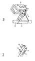
- Fig. 2 shows a measuring device for an inventive measurement by means of vehicle.
- the vehicle carries a four-legged tripod according to the invention and a commercially available total station as a measuring device.
- the exemplary embodiment is a device with the product name Trimble.
- Fig. 4 also shows a measuring device for a measurement according to the invention by means of a vehicle.
- the vehicle carries a console, in measuring function with a standard tacheometer as a measuring device.
- the exemplary embodiment is a device with the product name Trimble.
- the meter 30 is shown offset by 90 degrees for illustrative reasons. In reality, it is provided in the exemplary embodiment that the optics of the measuring device is directed in the longitudinal direction of the console 14 and points away from the console in the direction of an advance travel of the vehicle.
- the Trimble model lets you track passive targets with active target identification.
- the instrument captures and tracks many conventional prisms and targets, even over long distances.
- the target identification ensures the targeting of the right target.
- several prisms can also be used in the measuring area.
- the device has servo motors and angle sensors, as well as an error compensation.
- the device has an internal computer for the tasks described above, as well as its own power supply and a wireless remote transmission of data. This can be used to track work on a computer outside the channel.
- the measuring device is set up on the console by means of a tribrach, which can control the measuring device in a vertical position above the measuring point of the frog.
- a suitable tribrach for example, is the automatic tribrach AD-12 from GEO Laser. This tripod is combined with a laser, which also stands vertically when connected vertically to the housing of the meter.
- the console is adjusted by hand until the laser points exactly to the measuring point of the frog.
- the measuring device can generate the laser beam which is exactly vertical, and if the frog is provided with a reflector, the frog is executed with an automatically controlled mechanism.
- Fig. 4 In the measuring position after Fig. 4 is the console 14 with the rod 50 on the building sole and supports the vehicle via two other, not shown, extended and spaced supports on the building sole.
- the supports provide a stable position for the Vehicle.
- the supports are moved by hand and locked in the support position by clamping.
- the Fig. 3 shows the console 14 in the collapsed state.
- the console 14 is collapsed after completion of the measurement process to make the vehicle more manoeuvrable.
- the Fig. 5 to 7 show a vehicle according to the invention.
- the vehicle is three-wheeled, with two rear wheels 37,38 and a front wheel 36.
- the rear wheels 37,38 are provided with an electric drive.
- a four-wheeled vehicle is provided.
- the drive movement can be controlled electrically, in the embodiment of 0 to 10km per hour.
- the drive is powered by a battery which is arranged in a battery box 39.
- the battery box 39 is connected to the vehicle frame 35. From is located on the vehicle frame 35, a support surface 42 for the transport of measuring instruments and material.
- the vehicle includes a handlebar 41 as a steering.
- the handlebar 41 is rotatably held in the vehicle frame 35 and opens into a fork in which the wheel 36 is held.
- a bucket seat is provided for the driver in the vehicle frame.
- Fig. 4 Belong to the console described a guide rod 50, a guide 51 and a not shown attachment to the support surface 42 of the vehicle.
- the guide rod 50 extends in the illustrated embodiment according to the position of the vehicle vertically and is attached at both ends to the support surface 42 to the vehicle.
- the guide rod is in the illustrated embodiment in one piece, in other embodiments, the rod is telescopic to allow the rod to burst on the channel sole and to use the rod at the same time for a height measurement can.
- the guide 51 can be moved in the exemplary embodiment for adjusting the measuring device 30 up and down. Further, the guide 51 is pivotable on the rod, so that an adjustment can be made by pivoting.
- the further adjustment in the tunnel longitudinal direction is effected by insertion and / or removal of the console 14.
- the manual setting has been replaced in other embodiments by a setting with a hydraulic system.
- 3 vehicles are used for a measurement.
- the vehicle which carries the meter in the form shown, are still a vehicle that carries prisms and deflects the laser beam of the meter, and another vehicle provided with a tripod, in conjunction with a fixed measuring point on the channel bottom of the meter through the described prisms are targeted.
- the inventive vehicle works in the embodiment with a second, same vehicle together, which also carries a Trimble meter.
- Both vehicles travel in steps through the canal. During each step, the vehicles remain in sight.
- Each step is also a surveying step.
- foils are glued as a frog with a measuring point printed thereon by the drivers after the first stop on the channel base and takes place a survey of each frog in the form described above.
- both vehicles continue. However, the rear vehicle only goes up to the front frog to use for the next survey.
- the front vehicle drives a path that defines and stops the next survey step.
- the survey continues in the same overlapping manner.
- Fig. 8 shows another embodiment with a channel 60
- the channel 60 shows supply lines 61, which are held with tools 62. On the brackets conventional frogs 63 are provided.
- Fig. 9 to 11 four-wheeled vehicles 65 and 70 drove into the channel 60.
- the direction of travel is in Fig. 9 denoted by 68.
- Each vehicle carries a four-legged tripod 66. Each tripod is held raised and lowered and thereby deductible on the channel base and lifted from the channel base again.
- the tripods 66 of the vehicles 65 each carry a prism 67.
- the tripod 66 of the vehicle 70 carries a tachymeter 71.
- the tripod 66 is in Fig. 16 in a single view without a vehicle and shown together with a template 81.
- the template 81 consists of a glued on the building sole film, which can be removed again at the end of surveying.
- the vehicles according to Fig. 9 to 14 into the canal until each vehicle has reached a frog 63. Then the vehicles stop. After the first stop, the frogs on the hooks of the supply and media lines are removed from the hooks and placed on the tube sole.
- the positions at which the frogs are stored are pre-planned in the exemplary embodiment in a pipe layout plan. It is advantageous to mark or mark the positions of the frogs already in the tubes before their installation. Prior to installation, in the case of pipe jacking: before the pipes are lowered into the shaft
- the attachment of tags for frogs is performed in the embodiment with templates.
- the position of the feet of the Statives is marked on the building sole. This is true for any kind of tripods.
- the tripods After stopping, the tripods are placed on the tube sole. At the same time the surveying staff tries to settle on the markings for the feet of the tripods. Subsequently, the tripods are aligned with the measuring points of the frogs 63. For alignment then only slight shifts of the measuring devices are required. Thereafter, a conventional geodetic survey can take place with the total station and the two prism devices.
- the above-described survey represents a surveying step.
- the frogs remain lying and the tripods are raised and moved forward so far with the vehicles that the last vehicle in the direction of travel has arrived at the mean frog previously laid in the view.
- the middle vehicle advances until it reaches the first-placed frog.
- the first vehicle remains in sight, stops.
- a new frog is removed and placed on the channel floor. Subsequently, a surveying step takes place as described above.
- the surveying steps continue until the end of the channel.
- the frogs are left lying.
- the results can be compared with the previously obtained measurement results, so that the back measurement allows a control of the survey.
- the resulting surveying steps overlap each other in two measuring points.
- Fig. 15 shows how the vehicles drive back after full measurement. The frogs are hung up in the original form again.
- a backward measurement takes place. This means that during the reverse drive, a measurement takes place according to the measurement on the forward movement. However, the frogs do not remain after the survey, but the frogs are hung up again.
- the reverse direction is designated 80.
- Fig. 17 shows an embodiment in an off-scale representation in the context of vehicles 210 and the seated vehicle drivers who perform the survey.
- a crank is shown as a lifting device.
- the crank acts on a toothed rack via a pinion, so that with one turn in one direction a lifting movement and with a rotation in the other direction a lowering movement can be achieved.
- the tripods designated 211 have been sold on the building sole.
- the frogs 90 are placed after setting the tripods on the building sole.
- the frogs can be roughly aligned with the total station 92 easily.
- each tachymeter can be finely aligned with the laser described above on the associated frog.
- the measuring instruments After aligning the tachymeter with the frogs 90, the measuring instruments take a survey from each measuring point. The measuring devices take positions 91 and 92. This results in crossing, parallel measurements 93 and 94.
- the advantage is that with one measurement the other measurement can be controlled. After the measurement, the tripods 211 are raised again with the lifting device in order to transport the tripods with the measuring devices in the direction of measurement determined by the various measuring steps.
- Fig. 17 also shows an interaction with a further, arranged on the right vehicle 210 with tripod 211 and meters 91 and 92.
- the survey can be accelerated because two surveying steps are combined to form a Verticians Republic.
- Fig. 18 shows yet another embodiment.
- tripods find application 66 on which measuring devices 95 and 96 are mounted one above the other. Also here are parallel, intersecting measurements 97 and 98, with which a check can be made.
- the tachymeter is always placed at a distance of at least 1.5m from the respective targeted prism. This is based on the finding that the accuracy of tachymeters can diminish when the tachymeter are placed very close to a prism.
- the area affected by the decay may end at 0.2 m distance from the prism, but may also end at a distance of 1 m or 1.5 m. In the exemplary embodiment is not differentiated between individual tachymeters, but a distance is maintained, in which all occurring tachymeters measure without decreasing accuracy.
- Fig. 19 shows a four-wheeled vehicle.
- the wheels are arranged under a bottom plate 191 so that inadvertent contact while driving can not take place.
- the bottom plate 191 there is a recess 192.
- surveys through the bottom plate on a frog arranged underneath are possible.
- the wheels are located under fenders 201. Both take into account occupational safety. Hand and foot injuries are excluded.
- On the bottom plate is a rotatable seat with controls on the armrest.
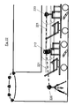
- Fig. 21 shows a schematic view of the beginning of a pipe jacking.
- a shaft 211 has first been run off.
- the reach of the shaft bottom is measured with a total station 212.
- This tachymeter 21 has a tripod for leveling.
- a tribrach a commercially available automatic tripod with the designation AD-12 is provided in the embodiment.
- measuring points 213 on the earth's surface or on the construction pit edge 215 are used.
- the measuring points are formed by prisms, which are targeted by the tachymeter.
- the measuring beams generated thereby are designated 214.
- the tachymeter 212 is also used to measure the channel from the viewpoint on the shaft bottom.
- first prisms 220 are measured, which are arranged on tripods 218 in the channel and are fobbed off to the measuring points of frogs 229.
- the tripods 218 have been transported by vehicles 219 in the channel.
- the prism 229 of the first stator 219 in the channel is dismantled and replaced by the tachymeter 212.
- the tachymeter 212 has previously been disassembled from its tripod in the manhole. In its place, the disassembled prism 220 has arrived. Thereafter, a measurement of the two prisms 220 in front of and behind the tachymeter 212 according to Fig. 22 one.
- each prism can be aligned to the respective measuring tachymeter.
Landscapes
- Engineering & Computer Science (AREA)
- Mining & Mineral Resources (AREA)
- Life Sciences & Earth Sciences (AREA)
- General Life Sciences & Earth Sciences (AREA)
- Radar, Positioning & Navigation (AREA)
- Remote Sensing (AREA)
- Environmental & Geological Engineering (AREA)
- Physics & Mathematics (AREA)
- Multimedia (AREA)
- General Physics & Mathematics (AREA)
- Geochemistry & Mineralogy (AREA)
- Geology (AREA)
- Excavating Of Shafts Or Tunnels (AREA)
- Length Measuring Devices With Unspecified Measuring Means (AREA)
- Length Measuring Devices By Optical Means (AREA)
- Lining And Supports For Tunnels (AREA)
- Geophysics And Detection Of Objects (AREA)
Applications Claiming Priority (3)
| Application Number | Priority Date | Filing Date | Title |
|---|---|---|---|
| DE102009022750 | 2009-05-26 | ||
| DE102010004264 | 2010-01-10 | ||
| DE102010004231 | 2010-01-10 |
Publications (3)
| Publication Number | Publication Date |
|---|---|
| EP2325601A2 true EP2325601A2 (fr) | 2011-05-25 |
| EP2325601A3 EP2325601A3 (fr) | 2012-05-30 |
| EP2325601B1 EP2325601B1 (fr) | 2015-09-30 |
Family
ID=42664614
Family Applications (3)
| Application Number | Title | Priority Date | Filing Date |
|---|---|---|---|
| EP10005172.1A Not-in-force EP2325601B1 (fr) | 2009-05-26 | 2010-05-18 | Mesurage de constructions souterraines, notamment lors de l'avancement souterrain, à l'aide d'embases crapaud |
| EP10005157.2A Not-in-force EP2256456B1 (fr) | 2009-05-26 | 2010-05-18 | Mesure de constructions souterraines, notamment lors de l'avancée souterraine |
| EP10005169.7A Not-in-force EP2256457B1 (fr) | 2009-05-26 | 2010-05-18 | Mesure de constructions souterraines, notamment lors de l'avancée souterraine, à l'aide de consoles |
Family Applications After (2)
| Application Number | Title | Priority Date | Filing Date |
|---|---|---|---|
| EP10005157.2A Not-in-force EP2256456B1 (fr) | 2009-05-26 | 2010-05-18 | Mesure de constructions souterraines, notamment lors de l'avancée souterraine |
| EP10005169.7A Not-in-force EP2256457B1 (fr) | 2009-05-26 | 2010-05-18 | Mesure de constructions souterraines, notamment lors de l'avancée souterraine, à l'aide de consoles |
Country Status (2)
| Country | Link |
|---|---|
| EP (3) | EP2325601B1 (fr) |
| DE (3) | DE102010020822A1 (fr) |
Families Citing this family (9)
| Publication number | Priority date | Publication date | Assignee | Title |
|---|---|---|---|---|
| CN102735223B (zh) * | 2011-07-20 | 2014-03-26 | 中铁四局集团第一工程有限公司 | 试车场路面圆形凸台定位方法 |
| DE102012219100A1 (de) | 2012-10-19 | 2014-04-24 | Oliver Gebauer | Messsystem und Verfahren zur Vermessung von Räumen |
| DE202016101759U1 (de) | 2016-04-04 | 2016-04-25 | VMT GmbH Gesellschaft für Vermessungstechnik | Vorrichtung zum Halten eines Vermessungsinstruments |
| CN108507549B (zh) * | 2018-05-28 | 2020-07-28 | 中国核工业二三建设有限公司 | 高温气冷堆堆内石墨砖和碳砖的安装测量方法 |
| CN113588914B (zh) * | 2021-06-22 | 2023-05-19 | 清华大学 | 一种隧道硐壁岩体检测装置及岩体扰动状态测试方法 |
| ZA202207686B (en) * | 2022-07-12 | 2022-10-26 | China Constr 7Th Eng Division Corp Ltd | Device and system for visual monitoring based on measuring robot |
| CN115573774B (zh) * | 2022-09-13 | 2023-05-05 | 温州信达交通工程试验检测有限公司 | 一种基于机器视觉自适应隧道变形的检测装置 |
| DE102023102055A1 (de) | 2023-01-27 | 2024-08-01 | VMT GmbH Gesellschaft für Vermessungstechnik | Vorrichtung zum Bestimmen der Position einer Tunnelbohrmaschine |
| DE202023100379U1 (de) | 2023-01-27 | 2023-02-14 | VMT GmbH Gesellschaft für Vermessungstechnik | Vorrichtung zum Bestimmen der Position einer Tunnelbohrmaschine |
Citations (10)
| Publication number | Priority date | Publication date | Assignee | Title |
|---|---|---|---|---|
| DE6910361U (de) | 1969-03-13 | 1969-07-10 | Heinz Josef Dipl Ing Knapp | Deckenverkleidungsplatte fuer innenraeume |
| DE2607280A1 (de) | 1976-02-23 | 1977-09-01 | Laser Light Gmbh | Vorrichtung zum ausrichten eines laser-leitstrahlgeraetes zu einem an anderem ort aufgestellten richtgeraet, z.b. einem richtfernrohr |
| DE3120010A1 (de) | 1981-05-20 | 1982-12-09 | Ed. Züblin AG, 7000 Stuttgart | Verfahren zur positionsbestimmung eines vorgepressten hohlprofilstrangs und vorrichtung zur durchfuehrung des verfahrens |
| DE3733553A1 (de) | 1987-10-03 | 1989-04-13 | Marx Hans Juergen | Vorrichtung zum steuern einer schildvortriebsmaschine |
| DE4017833C1 (fr) | 1990-06-02 | 1992-02-06 | Dyckerhoff & Widmann Ag, 8000 Muenchen, De | |
| EP1408344A1 (fr) | 2002-10-07 | 2004-04-14 | Geodata Ziviltechnikergesellschaft m.b.h. | Dispositif et méthode géodésique utilisant un laser à balayage |
| DE102004010114A1 (de) | 2004-02-27 | 2005-09-22 | Schlepütz, Roland | Positionsbestimmung von Erdbau-, Tunnelbau- und Rohrvortriebsmaschinen |
| DE69734622T2 (de) | 1996-03-18 | 2006-07-20 | Kabushiki Kaisha Topcon | Leitstrahlrichtungseinstellvorrichtung |
| DE102005012107A1 (de) | 2005-03-09 | 2006-09-21 | Angermeier Ingenieure Gmbh | Meßsystem und Verfahren zur geodätischen Vermessung von Objekten |
| DE102007014727A1 (de) | 2007-03-26 | 2008-11-20 | Keiper Gmbh & Co.Kg | Fahrzeugsitz, insbesondere Kraftfahrzeugsitz |
Family Cites Families (9)
| Publication number | Priority date | Publication date | Assignee | Title |
|---|---|---|---|---|
| DE3306470A1 (de) * | 1982-08-17 | 1984-02-23 | Peter G. Tiedemann GmbH Ingenieur- u. Vermessungsbüro, 2000 Hamburg | Verfahren und vorrichtung zum vermessen unterirdischer vortriebe |
| DE3404495A1 (de) * | 1984-02-09 | 1985-08-14 | Gewerkschaft Eisenhütte Westfalia, 4670 Lünen | Polygonzug-vermessungsverfahren und vermessungseinrichtung |
| JP2510043B2 (ja) | 1990-11-16 | 1996-06-26 | 佐藤工業株式会社 | レ―ザ―定点マ―キング機能を備えたレ―ザ―測量システム |
| JP2509491B2 (ja) * | 1991-10-04 | 1996-06-19 | 鹿島建設株式会社 | トンネルの内空変位計測方法 |
| JP2711328B2 (ja) * | 1993-05-24 | 1998-02-10 | 西松建設株式会社 | トンネルの測量方法 |
| JP2687102B2 (ja) * | 1995-02-24 | 1997-12-08 | 株式会社関電工 | 測定台車による管路等の自動位置測定法 |
| DE19507346C2 (de) * | 1995-03-02 | 2002-06-13 | Dyckerhoff & Widmann Ag | Verfahren zum Steuern einer Vortriebsmaschine bei der Herstellung eines unterirdischen Hohlraumprofils sowie Einrichtung zur Durchführung des Verfahrens |
| JP4841080B2 (ja) * | 2001-09-04 | 2011-12-21 | 西松建設株式会社 | トンネル坑内の形状測定システムおよび形状測定方法 |
| DE102007014527A1 (de) * | 2007-03-27 | 2008-10-02 | Wilhelm, Jürgen | Klemmstativ für Vermessungszwecke in Tunneln |
-
2010
- 2010-05-18 DE DE102010020822A patent/DE102010020822A1/de not_active Withdrawn
- 2010-05-18 EP EP10005172.1A patent/EP2325601B1/fr not_active Not-in-force
- 2010-05-18 EP EP10005157.2A patent/EP2256456B1/fr not_active Not-in-force
- 2010-05-18 EP EP10005169.7A patent/EP2256457B1/fr not_active Not-in-force
- 2010-05-18 DE DE102010020821A patent/DE102010020821A1/de not_active Withdrawn
- 2010-05-19 DE DE102010021818A patent/DE102010021818A1/de not_active Withdrawn
Patent Citations (10)
| Publication number | Priority date | Publication date | Assignee | Title |
|---|---|---|---|---|
| DE6910361U (de) | 1969-03-13 | 1969-07-10 | Heinz Josef Dipl Ing Knapp | Deckenverkleidungsplatte fuer innenraeume |
| DE2607280A1 (de) | 1976-02-23 | 1977-09-01 | Laser Light Gmbh | Vorrichtung zum ausrichten eines laser-leitstrahlgeraetes zu einem an anderem ort aufgestellten richtgeraet, z.b. einem richtfernrohr |
| DE3120010A1 (de) | 1981-05-20 | 1982-12-09 | Ed. Züblin AG, 7000 Stuttgart | Verfahren zur positionsbestimmung eines vorgepressten hohlprofilstrangs und vorrichtung zur durchfuehrung des verfahrens |
| DE3733553A1 (de) | 1987-10-03 | 1989-04-13 | Marx Hans Juergen | Vorrichtung zum steuern einer schildvortriebsmaschine |
| DE4017833C1 (fr) | 1990-06-02 | 1992-02-06 | Dyckerhoff & Widmann Ag, 8000 Muenchen, De | |
| DE69734622T2 (de) | 1996-03-18 | 2006-07-20 | Kabushiki Kaisha Topcon | Leitstrahlrichtungseinstellvorrichtung |
| EP1408344A1 (fr) | 2002-10-07 | 2004-04-14 | Geodata Ziviltechnikergesellschaft m.b.h. | Dispositif et méthode géodésique utilisant un laser à balayage |
| DE102004010114A1 (de) | 2004-02-27 | 2005-09-22 | Schlepütz, Roland | Positionsbestimmung von Erdbau-, Tunnelbau- und Rohrvortriebsmaschinen |
| DE102005012107A1 (de) | 2005-03-09 | 2006-09-21 | Angermeier Ingenieure Gmbh | Meßsystem und Verfahren zur geodätischen Vermessung von Objekten |
| DE102007014727A1 (de) | 2007-03-26 | 2008-11-20 | Keiper Gmbh & Co.Kg | Fahrzeugsitz, insbesondere Kraftfahrzeugsitz |
Also Published As
| Publication number | Publication date |
|---|---|
| DE102010020821A1 (de) | 2010-12-23 |
| EP2256456A3 (fr) | 2012-05-23 |
| EP2256457B1 (fr) | 2017-05-17 |
| EP2256457A3 (fr) | 2012-05-23 |
| DE102010021818A1 (de) | 2011-12-15 |
| EP2325601A3 (fr) | 2012-05-30 |
| EP2256456B1 (fr) | 2015-12-23 |
| EP2256457A2 (fr) | 2010-12-01 |
| EP2256456A2 (fr) | 2010-12-01 |
| DE102010020822A1 (de) | 2011-12-15 |
| EP2325601B1 (fr) | 2015-09-30 |
Similar Documents
| Publication | Publication Date | Title |
|---|---|---|
| EP2325601B1 (fr) | Mesurage de constructions souterraines, notamment lors de l'avancement souterrain, à l'aide d'embases crapaud | |
| AT403066B (de) | Verfahren zum ermitteln der abweichungen der ist-lage eines gleisabschnittes | |
| DE3120010C2 (fr) | ||
| EP2155968B1 (fr) | Train de finisseuses pour la fabrication d'une couche de revêtement routier en béton ou en asphalte | |
| EP2125597B1 (fr) | Procédé d'installation d'une machine-outil mobile | |
| CH666959A5 (de) | Vorrichtung zur positionsbestimmung eines vorgepressten hohlprofilstranges. | |
| EP0464363B1 (fr) | Procédé et dispositif pour la commande d'un bouclier | |
| DE2901908A1 (de) | Verfahren zur regelung der arbeitsbewegung eines ueber die ortsbrust bewegbaren schraemwerkzeuges einer streckenvortriebsmaschine und vorrichtung zur durchfuehrung dieses verfahrens | |
| DE4131673C2 (de) | Steuereinrichtung für eine Tunnelbohrmaschine | |
| DE102014005112A1 (de) | Messung unterirdischer Bauwerke, insbesonder beim unterirdischen Vortrieb, mit Prismen | |
| DE10129825B4 (de) | Herstellung einer Unterwasserwand | |
| DE102018006464B4 (de) | Vorrichtung zum Positionieren einer elektronischen Einheit an einer Erdbohrvorrichtung | |
| DE4439601A1 (de) | Verfahren zur Richtungssteuerung einer im Untertagebetrieb eingesetzten Maschine sowie zur Durchführung des Verfahrens geeigneten Maschine | |
| DE202010017291U1 (de) | Vorrichtung zur Messung unterirdischer Bauwerke, insbesondere beim unterirdischen Vortrieb, mit mindestens teilweiser mannloser Steuerung | |
| DE2364508C3 (de) | Anordnung zum Verlegen eines Dränrohres in einem vorbestimmten Gefälle | |
| DE3526197A1 (de) | Verfahren und vorrichtung zum einbringen von fertigteiltragelementen, insbesondere stahlbetonstuetzen, in bohrloecher | |
| DE102014015442B4 (de) | Verfahren zum Setzen von Leitdrahtträgern und Setzvorrichtung | |
| DE19507346C2 (de) | Verfahren zum Steuern einer Vortriebsmaschine bei der Herstellung eines unterirdischen Hohlraumprofils sowie Einrichtung zur Durchführung des Verfahrens | |
| EP3236203A1 (fr) | Procede et station totale destinés a commander un engin | |
| DE4420705A1 (de) | Verfahren und Vorrichtung zur kontinuierlichen automatischen Vermessung und Steuerung einer Vortriebsvorrichtung bei Tunnelbauten u. dgl. | |
| DE4314102C1 (de) | Ferngesteuerter Erdvortriebskörper | |
| DE19509135C1 (de) | Verfahren zum Einrichten einer Bohrlafette beim Strossenbohren | |
| EP3960389A1 (fr) | Système de marquage et procédé de marquage | |
| DE102019112535A1 (de) | Projektionsvorrichtung für Tiefbauarbeiten sowie zum Verfahren zum Steuern von Tiefbauarbeiten | |
| JPH0235116B2 (fr) |
Legal Events
| Date | Code | Title | Description |
|---|---|---|---|
| PUAI | Public reference made under article 153(3) epc to a published international application that has entered the european phase |
Free format text: ORIGINAL CODE: 0009012 |
|
| AK | Designated contracting states |
Kind code of ref document: A2 Designated state(s): AL AT BE BG CH CY CZ DE DK EE ES FI FR GB GR HR HU IE IS IT LI LT LU LV MC MK MT NL NO PL PT RO SE SI SK SM TR |
|
| AX | Request for extension of the european patent |
Extension state: BA ME RS |
|
| PUAL | Search report despatched |
Free format text: ORIGINAL CODE: 0009013 |
|
| RIC1 | Information provided on ipc code assigned before grant |
Ipc: E21D 9/00 20060101ALI20120420BHEP Ipc: G01C 7/06 20060101AFI20120420BHEP |
|
| AK | Designated contracting states |
Kind code of ref document: A3 Designated state(s): AL AT BE BG CH CY CZ DE DK EE ES FI FR GB GR HR HU IE IS IT LI LT LU LV MC MK MT NL NO PL PT RO SE SI SK SM TR |
|
| AX | Request for extension of the european patent |
Extension state: BA ME RS |
|
| 17P | Request for examination filed |
Effective date: 20121130 |
|
| 17Q | First examination report despatched |
Effective date: 20150225 |
|
| GRAP | Despatch of communication of intention to grant a patent |
Free format text: ORIGINAL CODE: EPIDOSNIGR1 |
|
| INTG | Intention to grant announced |
Effective date: 20150603 |
|
| GRAS | Grant fee paid |
Free format text: ORIGINAL CODE: EPIDOSNIGR3 |
|
| GRAA | (expected) grant |
Free format text: ORIGINAL CODE: 0009210 |
|
| AK | Designated contracting states |
Kind code of ref document: B1 Designated state(s): AL AT BE BG CH CY CZ DE DK EE ES FI FR GB GR HR HU IE IS IT LI LT LU LV MC MK MT NL NO PL PT RO SE SI SK SM TR |
|
| REG | Reference to a national code |
Ref country code: CH Ref legal event code: EP Ref country code: CH Ref legal event code: NV Representative=s name: ROTTMANN, ZIMMERMANN + PARTNER AG, CH Ref country code: GB Ref legal event code: FG4D Free format text: NOT ENGLISH |
|
| REG | Reference to a national code |
Ref country code: AT Ref legal event code: REF Ref document number: 752671 Country of ref document: AT Kind code of ref document: T Effective date: 20151015 |
|
| REG | Reference to a national code |
Ref country code: IE Ref legal event code: FG4D Free format text: LANGUAGE OF EP DOCUMENT: GERMAN |
|
| REG | Reference to a national code |
Ref country code: DE Ref legal event code: R096 Ref document number: 502010010368 Country of ref document: DE |
|
| REG | Reference to a national code |
Ref country code: NL Ref legal event code: FP |
|
| PG25 | Lapsed in a contracting state [announced via postgrant information from national office to epo] |
Ref country code: LV Free format text: LAPSE BECAUSE OF FAILURE TO SUBMIT A TRANSLATION OF THE DESCRIPTION OR TO PAY THE FEE WITHIN THE PRESCRIBED TIME-LIMIT Effective date: 20150930 Ref country code: LT Free format text: LAPSE BECAUSE OF FAILURE TO SUBMIT A TRANSLATION OF THE DESCRIPTION OR TO PAY THE FEE WITHIN THE PRESCRIBED TIME-LIMIT Effective date: 20150930 Ref country code: FI Free format text: LAPSE BECAUSE OF FAILURE TO SUBMIT A TRANSLATION OF THE DESCRIPTION OR TO PAY THE FEE WITHIN THE PRESCRIBED TIME-LIMIT Effective date: 20150930 Ref country code: GR Free format text: LAPSE BECAUSE OF FAILURE TO SUBMIT A TRANSLATION OF THE DESCRIPTION OR TO PAY THE FEE WITHIN THE PRESCRIBED TIME-LIMIT Effective date: 20151231 Ref country code: NO Free format text: LAPSE BECAUSE OF FAILURE TO SUBMIT A TRANSLATION OF THE DESCRIPTION OR TO PAY THE FEE WITHIN THE PRESCRIBED TIME-LIMIT Effective date: 20151230 |
|
| REG | Reference to a national code |
Ref country code: LT Ref legal event code: MG4D |
|
| PG25 | Lapsed in a contracting state [announced via postgrant information from national office to epo] |
Ref country code: HR Free format text: LAPSE BECAUSE OF FAILURE TO SUBMIT A TRANSLATION OF THE DESCRIPTION OR TO PAY THE FEE WITHIN THE PRESCRIBED TIME-LIMIT Effective date: 20150930 Ref country code: SE Free format text: LAPSE BECAUSE OF FAILURE TO SUBMIT A TRANSLATION OF THE DESCRIPTION OR TO PAY THE FEE WITHIN THE PRESCRIBED TIME-LIMIT Effective date: 20150930 |
|
| PG25 | Lapsed in a contracting state [announced via postgrant information from national office to epo] |
Ref country code: SK Free format text: LAPSE BECAUSE OF FAILURE TO SUBMIT A TRANSLATION OF THE DESCRIPTION OR TO PAY THE FEE WITHIN THE PRESCRIBED TIME-LIMIT Effective date: 20150930 Ref country code: IS Free format text: LAPSE BECAUSE OF FAILURE TO SUBMIT A TRANSLATION OF THE DESCRIPTION OR TO PAY THE FEE WITHIN THE PRESCRIBED TIME-LIMIT Effective date: 20160130 Ref country code: EE Free format text: LAPSE BECAUSE OF FAILURE TO SUBMIT A TRANSLATION OF THE DESCRIPTION OR TO PAY THE FEE WITHIN THE PRESCRIBED TIME-LIMIT Effective date: 20150930 Ref country code: CZ Free format text: LAPSE BECAUSE OF FAILURE TO SUBMIT A TRANSLATION OF THE DESCRIPTION OR TO PAY THE FEE WITHIN THE PRESCRIBED TIME-LIMIT Effective date: 20150930 Ref country code: ES Free format text: LAPSE BECAUSE OF FAILURE TO SUBMIT A TRANSLATION OF THE DESCRIPTION OR TO PAY THE FEE WITHIN THE PRESCRIBED TIME-LIMIT Effective date: 20150930 |
|
| REG | Reference to a national code |
Ref country code: FR Ref legal event code: PLFP Year of fee payment: 7 |
|
| PG25 | Lapsed in a contracting state [announced via postgrant information from national office to epo] |
Ref country code: PL Free format text: LAPSE BECAUSE OF FAILURE TO SUBMIT A TRANSLATION OF THE DESCRIPTION OR TO PAY THE FEE WITHIN THE PRESCRIBED TIME-LIMIT Effective date: 20150930 Ref country code: PT Free format text: LAPSE BECAUSE OF FAILURE TO SUBMIT A TRANSLATION OF THE DESCRIPTION OR TO PAY THE FEE WITHIN THE PRESCRIBED TIME-LIMIT Effective date: 20160201 Ref country code: RO Free format text: LAPSE BECAUSE OF FAILURE TO SUBMIT A TRANSLATION OF THE DESCRIPTION OR TO PAY THE FEE WITHIN THE PRESCRIBED TIME-LIMIT Effective date: 20150930 |
|
| REG | Reference to a national code |
Ref country code: DE Ref legal event code: R097 Ref document number: 502010010368 Country of ref document: DE |
|
| PLBE | No opposition filed within time limit |
Free format text: ORIGINAL CODE: 0009261 |
|
| STAA | Information on the status of an ep patent application or granted ep patent |
Free format text: STATUS: NO OPPOSITION FILED WITHIN TIME LIMIT |
|
| PG25 | Lapsed in a contracting state [announced via postgrant information from national office to epo] |
Ref country code: DK Free format text: LAPSE BECAUSE OF FAILURE TO SUBMIT A TRANSLATION OF THE DESCRIPTION OR TO PAY THE FEE WITHIN THE PRESCRIBED TIME-LIMIT Effective date: 20150930 |
|
| 26N | No opposition filed |
Effective date: 20160701 |
|
| REG | Reference to a national code |
Ref country code: CH Ref legal event code: PCAR Free format text: NEW ADDRESS: GARTENSTRASSE 28 A, 5400 BADEN (CH) |
|
| PG25 | Lapsed in a contracting state [announced via postgrant information from national office to epo] |
Ref country code: SI Free format text: LAPSE BECAUSE OF FAILURE TO SUBMIT A TRANSLATION OF THE DESCRIPTION OR TO PAY THE FEE WITHIN THE PRESCRIBED TIME-LIMIT Effective date: 20150930 |
|
| PG25 | Lapsed in a contracting state [announced via postgrant information from national office to epo] |
Ref country code: LU Free format text: LAPSE BECAUSE OF FAILURE TO SUBMIT A TRANSLATION OF THE DESCRIPTION OR TO PAY THE FEE WITHIN THE PRESCRIBED TIME-LIMIT Effective date: 20160518 |
|
| GBPC | Gb: european patent ceased through non-payment of renewal fee |
Effective date: 20160518 |
|
| REG | Reference to a national code |
Ref country code: IE Ref legal event code: MM4A |
|
| PG25 | Lapsed in a contracting state [announced via postgrant information from national office to epo] |
Ref country code: IE Free format text: LAPSE BECAUSE OF NON-PAYMENT OF DUE FEES Effective date: 20160518 Ref country code: GB Free format text: LAPSE BECAUSE OF NON-PAYMENT OF DUE FEES Effective date: 20160518 |
|
| REG | Reference to a national code |
Ref country code: FR Ref legal event code: PLFP Year of fee payment: 8 |
|
| REG | Reference to a national code |
Ref country code: FR Ref legal event code: PLFP Year of fee payment: 9 |
|
| PG25 | Lapsed in a contracting state [announced via postgrant information from national office to epo] |
Ref country code: HU Free format text: LAPSE BECAUSE OF FAILURE TO SUBMIT A TRANSLATION OF THE DESCRIPTION OR TO PAY THE FEE WITHIN THE PRESCRIBED TIME-LIMIT; INVALID AB INITIO Effective date: 20100518 Ref country code: SM Free format text: LAPSE BECAUSE OF FAILURE TO SUBMIT A TRANSLATION OF THE DESCRIPTION OR TO PAY THE FEE WITHIN THE PRESCRIBED TIME-LIMIT Effective date: 20150930 Ref country code: CY Free format text: LAPSE BECAUSE OF FAILURE TO SUBMIT A TRANSLATION OF THE DESCRIPTION OR TO PAY THE FEE WITHIN THE PRESCRIBED TIME-LIMIT Effective date: 20150930 |
|
| PG25 | Lapsed in a contracting state [announced via postgrant information from national office to epo] |
Ref country code: MK Free format text: LAPSE BECAUSE OF FAILURE TO SUBMIT A TRANSLATION OF THE DESCRIPTION OR TO PAY THE FEE WITHIN THE PRESCRIBED TIME-LIMIT Effective date: 20150930 Ref country code: TR Free format text: LAPSE BECAUSE OF FAILURE TO SUBMIT A TRANSLATION OF THE DESCRIPTION OR TO PAY THE FEE WITHIN THE PRESCRIBED TIME-LIMIT Effective date: 20150930 Ref country code: MT Free format text: LAPSE BECAUSE OF FAILURE TO SUBMIT A TRANSLATION OF THE DESCRIPTION OR TO PAY THE FEE WITHIN THE PRESCRIBED TIME-LIMIT Effective date: 20150930 Ref country code: MC Free format text: LAPSE BECAUSE OF FAILURE TO SUBMIT A TRANSLATION OF THE DESCRIPTION OR TO PAY THE FEE WITHIN THE PRESCRIBED TIME-LIMIT Effective date: 20150930 |
|
| PG25 | Lapsed in a contracting state [announced via postgrant information from national office to epo] |
Ref country code: BG Free format text: LAPSE BECAUSE OF FAILURE TO SUBMIT A TRANSLATION OF THE DESCRIPTION OR TO PAY THE FEE WITHIN THE PRESCRIBED TIME-LIMIT Effective date: 20150930 |
|
| PGFP | Annual fee paid to national office [announced via postgrant information from national office to epo] |
Ref country code: DE Payment date: 20180531 Year of fee payment: 9 Ref country code: CH Payment date: 20180405 Year of fee payment: 9 |
|
| PGFP | Annual fee paid to national office [announced via postgrant information from national office to epo] |
Ref country code: FR Payment date: 20180528 Year of fee payment: 9 Ref country code: AT Payment date: 20180523 Year of fee payment: 9 Ref country code: NL Payment date: 20180518 Year of fee payment: 9 Ref country code: BE Payment date: 20180530 Year of fee payment: 9 Ref country code: IT Payment date: 20180509 Year of fee payment: 9 |
|
| PG25 | Lapsed in a contracting state [announced via postgrant information from national office to epo] |
Ref country code: AL Free format text: LAPSE BECAUSE OF FAILURE TO SUBMIT A TRANSLATION OF THE DESCRIPTION OR TO PAY THE FEE WITHIN THE PRESCRIBED TIME-LIMIT Effective date: 20150930 |
|
| REG | Reference to a national code |
Ref country code: DE Ref legal event code: R119 Ref document number: 502010010368 Country of ref document: DE |
|
| REG | Reference to a national code |
Ref country code: CH Ref legal event code: PL |
|
| REG | Reference to a national code |
Ref country code: NL Ref legal event code: MM Effective date: 20190601 |
|
| REG | Reference to a national code |
Ref country code: AT Ref legal event code: MM01 Ref document number: 752671 Country of ref document: AT Kind code of ref document: T Effective date: 20190518 |
|
| PG25 | Lapsed in a contracting state [announced via postgrant information from national office to epo] |
Ref country code: AT Free format text: LAPSE BECAUSE OF NON-PAYMENT OF DUE FEES Effective date: 20190518 Ref country code: CH Free format text: LAPSE BECAUSE OF NON-PAYMENT OF DUE FEES Effective date: 20190531 Ref country code: LI Free format text: LAPSE BECAUSE OF NON-PAYMENT OF DUE FEES Effective date: 20190531 |
|
| REG | Reference to a national code |
Ref country code: BE Ref legal event code: MM Effective date: 20190531 |
|
| PG25 | Lapsed in a contracting state [announced via postgrant information from national office to epo] |
Ref country code: DE Free format text: LAPSE BECAUSE OF NON-PAYMENT OF DUE FEES Effective date: 20191203 Ref country code: IT Free format text: LAPSE BECAUSE OF NON-PAYMENT OF DUE FEES Effective date: 20190518 Ref country code: NL Free format text: LAPSE BECAUSE OF NON-PAYMENT OF DUE FEES Effective date: 20190601 |
|
| PG25 | Lapsed in a contracting state [announced via postgrant information from national office to epo] |
Ref country code: BE Free format text: LAPSE BECAUSE OF NON-PAYMENT OF DUE FEES Effective date: 20190531 |
|
| PG25 | Lapsed in a contracting state [announced via postgrant information from national office to epo] |
Ref country code: FR Free format text: LAPSE BECAUSE OF NON-PAYMENT OF DUE FEES Effective date: 20190531 |