EP2324546B1 - Method and apparatus for extracting of cable elements - Google Patents
Method and apparatus for extracting of cable elements Download PDFInfo
- Publication number
- EP2324546B1 EP2324546B1 EP09775628.2A EP09775628A EP2324546B1 EP 2324546 B1 EP2324546 B1 EP 2324546B1 EP 09775628 A EP09775628 A EP 09775628A EP 2324546 B1 EP2324546 B1 EP 2324546B1
- Authority
- EP
- European Patent Office
- Prior art keywords
- cable
- clamping
- base part
- cable element
- pipe
- Prior art date
- Legal status (The legal status is an assumption and is not a legal conclusion. Google has not performed a legal analysis and makes no representation as to the accuracy of the status listed.)
- Not-in-force
Links
Images


Classifications
-
- H—ELECTRICITY
- H02—GENERATION; CONVERSION OR DISTRIBUTION OF ELECTRIC POWER
- H02G—INSTALLATION OF ELECTRIC CABLES OR LINES, OR OF COMBINED OPTICAL AND ELECTRIC CABLES OR LINES
- H02G1/00—Methods or apparatus specially adapted for installing, maintaining, repairing or dismantling electric cables or lines
- H02G1/06—Methods or apparatus specially adapted for installing, maintaining, repairing or dismantling electric cables or lines for laying cables, e.g. laying apparatus on vehicle
- H02G1/08—Methods or apparatus specially adapted for installing, maintaining, repairing or dismantling electric cables or lines for laying cables, e.g. laying apparatus on vehicle through tubing or conduit, e.g. rod or draw wire for pushing or pulling
- H02G1/081—Methods or apparatus specially adapted for installing, maintaining, repairing or dismantling electric cables or lines for laying cables, e.g. laying apparatus on vehicle through tubing or conduit, e.g. rod or draw wire for pushing or pulling using pulling means at cable ends, e.g. pulling eyes or anchors
-
- H—ELECTRICITY
- H02—GENERATION; CONVERSION OR DISTRIBUTION OF ELECTRIC POWER
- H02G—INSTALLATION OF ELECTRIC CABLES OR LINES, OR OF COMBINED OPTICAL AND ELECTRIC CABLES OR LINES
- H02G1/00—Methods or apparatus specially adapted for installing, maintaining, repairing or dismantling electric cables or lines
- H02G1/06—Methods or apparatus specially adapted for installing, maintaining, repairing or dismantling electric cables or lines for laying cables, e.g. laying apparatus on vehicle
- H02G1/08—Methods or apparatus specially adapted for installing, maintaining, repairing or dismantling electric cables or lines for laying cables, e.g. laying apparatus on vehicle through tubing or conduit, e.g. rod or draw wire for pushing or pulling
-
- H—ELECTRICITY
- H02—GENERATION; CONVERSION OR DISTRIBUTION OF ELECTRIC POWER
- H02G—INSTALLATION OF ELECTRIC CABLES OR LINES, OR OF COMBINED OPTICAL AND ELECTRIC CABLES OR LINES
- H02G3/00—Installations of electric cables or lines or protective tubing therefor in or on buildings, equivalent structures or vehicles
- H02G3/28—Installations of cables, lines, or separate protective tubing therefor in conduits or ducts pre-established in walls, ceilings or floors
Definitions
- the invention relates to a method for extracting cable elements from cable ducts in cable ducts, wherein the cable element clamped with a clamping device and exerted a tensile force on the cable element and the cable element is pulled out of the cable tube, wherein the cable element is clamped in the cable duct and gradually pulled out of the cable tube in that, after clamping with the clamping device, the cable element is pulled a distance substantially in the longitudinal direction of the cable element from the cable tube, then the clamping device is opened and moved back by the distance in the direction of the cable tube, the cable element is clamped again and pulled out by the distance.
- the present invention relates to a device for extracting cable elements from cable ducts in cable ducts, with a clamping device for clamping the cable element and a device for exerting a tensile force on the cable element for pulling the cable element out of the cable duct.
- a technique for laying fiber optic cables In the process, a pilot hole is first dug between an input shaft and an output shaft by means of a mole machine, and then a flexible guide wire is drawn into the pilot hole.
- the guide wire is connected on the side of the output shaft via a connecting part with the cable bundle to be recovered.
- a device for cyclically pulling the guidewire In the entrance shaft, a device for cyclically pulling the guidewire is attached.
- the extraction device comprises a frame with a plate which comes to rest at the entrance of the pilot bore.
- two hydraulically actuated cylinders are provided, at the ends of which a clamping device for the guide wire is fastened.
- the guide wire and the wire bundle connected thereto are gradually pulled through the pilot hole by a plurality of operation cycles of the cylinders by repeatedly clamping the guide wire, advancing the cylinder pistons so that the guide wire is pulled out a certain distance, and the clamp is released , and the pistons are driven back.
- the WO 2008/031536 A1 shows a method and apparatus for replacing underground cables, wherein a pit is excavated and a pulling force is applied to the underground cable by means of a machine located outside the pit. These are not cable elements that are routed in cable ducts in cable ducts.
- the CH 460 897 A describes a device for laying cables, pipes and the like with which the cable is clamped and moved by lever-like movement of the clamping device, piece by piece. This is a device for laying cables and not for extracting cables, as is the case with the present application. The tensile forces required to extract cable elements from conduits in cable ducts could not be applied to the apparatus of this prior art.
- the shows GB 2 126 800 A a device for moving underground cables, wherein the soil is loosened along the cable, in order to prepare for the extraction or replacement of the cable without having to dig up the earth surface on the entire transfer line.
- a cable clearing device is moved along the cable, thereby loosening the surrounding soil.
- operable element covers both complete cables, as they are commonly laid in cable conduits, as well as parts of cables, such as. individual strands or bundles of strands of a cable.
- the present invention relates primarily to so-called tube cables, in particular for telecommunications, power supply, television, etc., which are usually laid in a plastic or concrete pipe.
- tube cables in particular for telecommunications, power supply, television, etc.
- a plastic or concrete pipe usually laid in a plastic or concrete pipe.
- Tubular cables are often provided on the outside with a water-repellent medium, especially tar, which prevents the ingress of moisture into the interior of the cable.
- Both the water-repellent medium and the sheath of the cable which may be made of plastic or lead, usually sticks to the inside of the cable tube, whereby a withdrawal of such cables is difficult.
- This adhesive effect is enhanced by the fact that frictional heat is generated during the drawing of such a cable, which softens the water-repellent medium but also the cable sheath and makes a connection with the inside of the cable tube.
- a heat development can also occur with already laid cables by the flow of current through the strands of the cable. Dirt in the cable leads to a connection between the cable and the cable and makes it difficult to remove the cable.
- the object of the present invention is to provide an above-mentioned method for extracting cable elements from cable ducts in cable ducts, which is as simple, quick and inexpensive to carry out, and avoids or at least reduces the disadvantages of known methods.
- Another object is to provide an above-mentioned device for extracting cable elements from cable ducts in cable ducts, which is as small as possible and inexpensive and inexpensive to produce and allows rapid and easy use in a cable duct.
- the device should be able to apply a corresponding tensile force to the cable element, so that a solution of the cable element from the cable tube is possible, and a rapid extraction of the cable element is ensured from the cable tube.
- the object of the invention is achieved by an above-mentioned method in which the clamping device is moved on a slide about the distances translationally relative to a base part, and with a arranged between the base part and the carriage drive to achieve the translational movement of the carriage relative to the Base part, a tensile force is applied to the cable element substantially in the longitudinal direction of the cable element, and the base part is supported via an adapter for placement at the end of the cable tube to a wall of the cable duct surrounding the cable tube .
- the procedure can also be carried out directly in the cable duct.
- the method according to the invention is used in particular when the cables or cable elements stick in the cable tube. After the solution of the cable element in the cable tube and conventional Method for extracting the cable elements are used.
- the drawn from the cable conduit cable element is guided out of the cable duct and rolled up.
- the leadership of the cable element from the cable duct can be done by appropriate, known per se pulleys or the like.
- the rolled-up, extended cable element can then be recycled, in particular the recycling of copper usually contained in the cable, the copper strands are supplied.
- the cable element pulled out of the cable tube can also be cut.
- cable pieces can be produced in the desired length, their removal is easier.
- this method is suitable for busy roads, where it is not possible to redirect the traffic around the shaft to arrange a winch and drum.
- a corresponding solvent can be introduced before the extraction process.
- cables are often surrounded by a tar layer. This can be softened, for example, by using fatty acid methyl ester (biodiesel).
- the solvent can be very easily and quickly introduced into the cable tube by being atomized and injected into the cable tube.
- conventional compressors can be used.
- the cable element after detaching the cable element from the cable tube by the stepwise extraction according to the invention from the cable tube, the cable element can be continuously pulled out of the cable tube.
- a known continuous exhaust process which can be carried out for example with a corresponding Quetschwinde, a faster extraction is usually possible.
- the cable element is preferably clamped hydraulically. With corresponding hydraulic cylinders, a sufficiently large clamping force can be applied to the cable element.
- a particularly high clamping force for example in the range of a few tons, so that the cable sheath is firmly connected to the interior of the cable, so that a relative movement between individual cable elements can not take place during the extraction process.
- the object of the invention is also achieved by an above-mentioned device for extracting cable elements from cable ducts in cable ducts, wherein the clamping device is arranged on a carriage, which carriage is arranged translationally movable on a base part substantially in the longitudinal direction of the cable element, and the device for exercise a tensile force on the cable element is provided substantially in the longitudinal direction of the cable element by at least one arranged between the base part and the carriage drive to achieve the translational movement of the carriage relative to the base part, and the base part is formed for support on a wall of the cable duct surrounding the cable tube in that an adapter for arranging at the end of the cable tube is arranged on the base part.
- Such a construction of a device for extracting cable elements makes possible a small and lightweight construction, which can be quickly and easily inserted into a cable duct and used there. It is essential that the device or its base part is supported on a wall surrounding the cable tube, so that the applied tensile force on the cable element is substantially completely available for the extraction process.
- the corresponding counterforce to the tensile force is introduced via the adapter in the wall of the cable tray, without supporting structures or the like. Be charged.
- corresponding support structures which make the device difficult to handle, usually omitted.
- the adapter partially protrudes into the cable tube with the cable element to be pulled out.
- corresponding wedges or the like can also be arranged between the adapter and the inner wall of the cable tube.
- the clamping device is releasably connected to the carriage. Due to the detachable connection, the device can be divided and thus more easily introduced into the cable duct.
- the releasable connection between the clamping device and slide preferably allows a tool-free connection and separation.
- the clamping device also variously to be arranged on the carriage, depending on the space in the cable tray.
- the clamping device can be arranged on the carriage to make the clamping of the cable element within the carriage or seen in the pulling direction are arranged in front of the carriage, so that the clamping of the cable element takes place outside of the carriage.
- the adapter is rotationally symmetrical and usually designed according to the cable tube.
- the adapter will thus preferably have a cylindrical or partially cylindrical shape. This ensures that the entire device can be rotated 360 ° relative to the cable tube and can be placed in a desired position depending on the available space.
- the clamping device preferably comprises at least one hydraulic cylinder.
- the one or more hydraulic cylinders are connected to a corresponding hydraulic unit or a hand pump.
- other, for example, mechanical clamping devices are possible, but which are maintenance-prone and require more time for the clamping operation.
- the clamping device has two, preferably profiled, clamping plates. These profiled, for example, corrugated or serrated clamping plates are pressed into the cable element to be pulled out and prevent it from slipping, so that the full tensile force can act on the cable element.
- flat clamping plates can also suitably shaped clamping plates, such as a U-shaped lower clamping profile, in which the cable to be pulled or Cable element is inserted and an inserted between the legs of the U-shaped profile upper clamping plate can be used.
- the drive for achieving a translational movement of the carriage relative to the base part is preferably formed by at least one hydraulic cylinder.
- the hydraulic cylinders are connected to a corresponding hydraulic unit or a hand pump.
- two hydraulic cylinders are best arranged on both sides of the cable element to be pulled out. With such hydraulic cylinders, a high force can be achieved with a small size.
- the hydraulic cylinders are connected to corresponding controls.
- there are two operating elements wherein a control element is connected to the hydraulic cylinders of the clamping device and controls the clamping of the cable element accordingly, while the other control element is connected to the hydraulic cylinders of the drive to achieve the translational movement of the carriage and the forward and backward movement of the Carriage relative to the base part controls. Operation can be manual or automatic or semi-automatic.
- the base part is preferably formed by two parallel rails, between which the cable element to be pulled out of the cable tube can be arranged. This construction can be easily manufactured and is robust due to the symmetrical arrangement.
- a device for introducing a solvent is provided in the cable tube, so that before or during the extraction process, the possibly existing water-repellent medium on the outside of the cable element softens and thus the extraction process can be facilitated.
- a solvent for the tar often used on the outside of the cable element fatty acid methyl ester is particularly suitable.
- biodiesel is relatively cheap and biodegradable, so contamination of the soil is harmless.
- corresponding support elements or devices for attachment of support elements may be provided on the base member.
- such devices may be formed by tabs or the like.
- a device connectable to the carriage can be used to continuously extend the cable element, thereby enabling a more rapid extraction process.
- a device for continuous extraction of the cable element may be formed for example by a winch or Quetschwinde.
- a device for cutting off the cable element which can also be arranged, for example, on the carriage and can be connected to it, it is possible to cut off the cable element at desired locations in order to produce, for example, easily transportable short cable pieces.
- Fig. 1 shows a cable duct 1 in cross section, in which a plurality of conduits 2 converge.
- the cable duct 1 is accessible via a usually vertically arranged access 3, which is closed with a corresponding cover (not shown).
- cable duct 1 run several cable tubes 2 together, each having one or more cable elements 5.
- the cable ducts 2 may be provided with a lining 4, for example made of plastic.
- the cable elements 5 are divided and relocated, for example, in corresponding pipes for connection with the individual households or the cable elements merely connected to each other.
- the cable elements 5 are surrounded by tar, plastic, in particular PVC, or other materials which stick in the cable tube 2 or the liner 4 and can make the extraction process of such a cable element 5 more difficult.
- Fig. 2 schematically shows a pull-out according to the prior art, in which the cable element 5 is guided over deflection rollers 6 via the vertical access 3 from the cable duct 1, and outside of the cable duct 1, a corresponding tensile force F is applied to the cable element.
- the tensile force F can be generated by appropriate winches or the like. (Not shown). Due to the mentioned sticking of the cable elements 5 in the cable tube 2 usually has a particularly high tensile force F act on the cable element 5 to allow a pull out. For example, tensile forces of 3000-6000 kg or more are common.
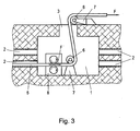
- Fig. 3 shows the principle of another method of the prior art for extracting a cable element 5 from the cable tube 2 in a cable duct 1, wherein a device 8 for applying a tensile force F on the cable element 5 in the cable duct 1 is arranged.
- a device 8 for applying a tensile force F on the cable element 5 in the cable duct 1 is arranged.
- Such a device 8 for example, by a Quetschwinde, consisting of two rollers 9, between which the cable element 5 is clamped formed.
- Such a device 8, which can also generate the usual tensile forces F for pulling out a cable element 5 from a cable tube 2, and also corresponding support means (not shown) are particularly bulky and heavy, which is why their handling in the cable duct 1 is also complex.
- the Figs. 4A to 4D show the principle of the method according to the invention and the device according to the invention for extracting a cable element 5 from the cable tube 2 in a cable duct 1.
- the device 10 essentially consists of a base part 11 and a relative to the base part 11 substantially in the longitudinal direction of the cable element 5 translationally movable carriage 12 with a clamping device 13.
- the base part 11 has an adapter 14 for arrangement and support at the end of the cable tube 2 with the cable element 5 to be pulled out.
- the base member 11 is disposed directly in front of the cable tube 2 of the cable element 5 to be pulled out and supports itself on the wall 15, which surrounds the opening of the cable tube 2, accordingly.
- the entire tensile force of, for example 2-6 t can be applied directly and without danger to the cable element 5 to be pulled out.
- the safety during the extraction process can be substantially increased since the tensile force is applied directly to the cable element 5 and no tension occurs in the cable duct 1.
- the device 10 according to the invention can be made particularly small and light, so that it can be placed quickly and easily in the cable duct 1. According to Fig. 4A the cable element 5 is clamped by the clamping device 13 and then according to Fig.
- a solvent for example fatty acid methyl ester (biodiesel)
- biodiesel fatty acid methyl ester
- FIGS. 5 and 6 show an embodiment of a device 10 according to the invention for extracting a cable element 5 from a cable tube 2 in a cable duct 1 in side view and Top view.
- the device 10 consists of a base part 11, which is essentially formed by two parallel rails 17.
- the base part 11 is provided with an adapter 14, or formed integrally therewith, which projects partially into the cable tube 2.
- the adapter 14 is rotationally symmetrical, as is the usually circularly shaped cable tube 2, so that the entire device 10 for extracting the cable element 5 from the cable tube 2 can be rotated 360 ° relative to the cable tube 2. This is particularly advantageous in tight spaces in the cable duct 1, since the device 10 can be arranged so that sufficient space for clamping the cable element 5 is available.
- the carriage 12 is also formed from rails 18 which are slidably disposed on the rails 17 of the base member 11 in the longitudinal direction of the cable member 5.
- the clamping device 13 is detachably connected to the carriage 12 and, in the illustrated variant, has three hydraulic cylinders 20 for clamping the cable element 5.
- the hydraulic cylinders 19, 20 are connected to a corresponding hydraulic unit or a hand pump (not shown).
- On the base member 11 devices 21 may be provided for attachment of support members 22.
- the device 10 can be easily divided and the items can be quickly and easily introduced into the cable duct 1.
- the clamping device 13 also as in Fig. 7 arranged to arrange.
- the clamping device 13 with respect to the variant according to the Fig. 5 and 6 turned and placed in the pulling direction in front of the carriage 12, namely outside of the carriage 12, and connected thereto by corresponding connecting elements. In this way, in the case of lack of space, laterally next to the cable element 5, this can be clamped more easily and pulled out of the cable tube 2.
- the clamping device 13 preferably has two correspondingly profiled clamping plates 23, between which the cable element 5 is squeezed.
- the Fig. 5-7 show only one of many possible embodiments for carrying out the method according to the invention. Due to the direct application of the method and the device in the cable duct 1 at the opening of the cable tube 2 with the cable element 5 to be pulled out, the device 10 can be particularly simple and easy to set up and quickly arranged in the cable duct 1 and removed again from this.
Description
Die Erfindung betrifft ein Verfahren zum Extrahieren von Kabelelementen aus Kabelrohren in Kabelschächten, wobei das Kabelelement mit einer Klemmvorrichtung geklemmt und auf das Kabelelement eine Zugkraft ausgeübt und das Kabelelement aus dem Kabelrohr gezogen wird, wobei das Kabelelement im Kabelschacht geklemmt und schrittweise aus dem Kabelrohr gezogen wird, indem das Kabelelement nach dem Klemmen mit der Klemmvorrichtung eine Strecke im Wesentlichen in Längsrichtung des Kabelelements aus dem Kabelrohr gezogen wird, danach die Klemmvorrichtung geöffnet und um die Strecke in Richtung des Kabelrohres zurückbewegt wird, das Kabelelement erneut geklemmt und um die Strecke herausgezogen wird.The invention relates to a method for extracting cable elements from cable ducts in cable ducts, wherein the cable element clamped with a clamping device and exerted a tensile force on the cable element and the cable element is pulled out of the cable tube, wherein the cable element is clamped in the cable duct and gradually pulled out of the cable tube in that, after clamping with the clamping device, the cable element is pulled a distance substantially in the longitudinal direction of the cable element from the cable tube, then the clamping device is opened and moved back by the distance in the direction of the cable tube, the cable element is clamped again and pulled out by the distance.
Ebenso betrifft die vorliegende Erfindung eine Vorrichtung zum Extrahieren von Kabelelementen aus Kabelrohren in Kabelschächten, mit einer Klemmvorrichtung zum Klemmen des Kabelelements und einer Vorrichtung zur Ausübung einer Zugkraft auf das Kabelelement zum Ausziehen des Kabelelements aus dem Kabelrohr.Also, the present invention relates to a device for extracting cable elements from cable ducts in cable ducts, with a clamping device for clamping the cable element and a device for exerting a tensile force on the cable element for pulling the cable element out of the cable duct.
Aus der
Die
Die
Schließlich zeigt die
Unter den Begriff "Kabelelement" fallen sowohl komplette Kabel, wie sie üblicherweise in Kabelrohren verlegt sind, als auch Teile von Kabeln, wie z.B. einzelne Litzen oder Bündel von Litzen eines Kabels.The term "cable element" covers both complete cables, as they are commonly laid in cable conduits, as well as parts of cables, such as. individual strands or bundles of strands of a cable.
Die vorliegende Erfindung bezieht sich in erster Linie auf so genannte Röhrenkabel, insbesondere für die Telekommunikation, Stromversorgung, Fernsehen, usw., welche üblicherweise in einem Kunststoff- oder Betonrohr verlegt werden. Meistens wird nur ein Kabel pro Kabelrohr, welches einen Durchmesser von beispielsweise 100 mm aufweist, verlegt. Es können aber auch mehrere Kabel oder auch andere Leitungen in derartigen Kabelrohren verlegt werden. Röhrenkabel sind an der Außenseite häufig mit einem wasserabweisenden Medium, insbesondere Teer, versehen, welches das Eindringen von Feuchtigkeit in das Innere des Kabels verhindert. Sowohl das wasserabweisende Medium als auch der Mantel des Kabels, welcher aus Kunststoff oder Blei bestehen kann, klebt in der Regel an der Innenseite des Kabelrohres an, wodurch ein Ausziehen derartiger Kabel erschwert wird. Verstärkt wird diese Klebewirkung dadurch, dass während des Einziehens eines solchen Kabels Reibungswärme entsteht, welche das wasserabweisende Medium aber auch den Kabelmantel erweicht und mit der Innenseite des Kabelrohres eine Verbindung herstellt. Eine Wärmeentwicklung kann auch bei bereits verlegten Kabeln durch den Stromfluss durch die Litzen des Kabels entstehen. Auch Schmutz im Kabelrohr führt zu einer Verbindung zwischen dem Kabelrohr und dem Kabel und erschwert ein Ausziehen des Kabels.The present invention relates primarily to so-called tube cables, in particular for telecommunications, power supply, television, etc., which are usually laid in a plastic or concrete pipe. Mostly, only one cable per cable tube, which has a diameter of, for example, 100 mm, laid. But it can also be laid several cables or other lines in such conduits. Tubular cables are often provided on the outside with a water-repellent medium, especially tar, which prevents the ingress of moisture into the interior of the cable. Both the water-repellent medium and the sheath of the cable, which may be made of plastic or lead, usually sticks to the inside of the cable tube, whereby a withdrawal of such cables is difficult. This adhesive effect is enhanced by the fact that frictional heat is generated during the drawing of such a cable, which softens the water-repellent medium but also the cable sheath and makes a connection with the inside of the cable tube. A heat development can also occur with already laid cables by the flow of current through the strands of the cable. Dirt in the cable leads to a connection between the cable and the cable and makes it difficult to remove the cable.
Zum Ausziehen von Kabeln aus Kabelrohren in Kabelschächten müssen daher relativ hohe Zugkräfte auf das Kabel aufgebracht werden, welche in der Lage sind, die Verbindung zwischen dem Kabel und dem Kabelrohr zu lösen und das Gewicht des Kabels zu ziehen. Nachdem die Kabelschächte, welche einen Zugang zu den Kabelrohren bieten, meist relativ klein sind, werden die Vorrichtungen zum Ausziehen des Kabels aus den Kabelrohren häufig außerhalb der Schächte angeordnet. Dies erfordert die Anordnung entsprechender Umlenkrollen, welche das auszuziehende Kabel vom Ende des Kabelrohres bis zur Vorrichtung zum Aufbringen einer Zugkraft auf das Kabel, z.B. eine entsprechende Seilwinde, leiten. Bei jeder Umlenkrolle geht ein beträchtlicher Teil der Zugkraft verloren, welcher durch diese aufgenommen werden muss. Bei der Anordnung mehrerer Umlenkrollen steht schließlich nur mehr ein Bruchteil der von der Seilwinde aufgebrachten Zugkraft für das Herausziehen des Kabels aus dem Kabelrohr zur Verfügung. Um jedoch die häufig im Kabelrohr festgeklebten Kabel lösen zu können, muss die Seilwinde eine entsprechend hohe Zugkraft liefern können. Dementsprechend voluminös und schwer müssen die Seilwinde aber auch die Umlenkrollen ausgebildet sein, wodurch sich der Ausziehvorgang besonders beschwerlich und auch Zeit- und Kostenintensiv, gestaltet.Therefore, to pull cables from conduits into conduits, relatively high tensile forces must be applied to the conduit, which are capable of releasing the connection between the conduit and the conduit and pulling the weight of the cable. After the cable ducts, which provide access to the cable ducts, are usually relatively small, the devices for removing the cable from the cable ducts are often arranged outside the ducts. This requires the arrangement of corresponding pulleys, which pull the cable to be pulled out from the end of the cable tube to the device for applying a tensile force to the cable, e.g. a corresponding winch, conduct. With each pulley, a considerable part of the traction is lost, which must be absorbed by them. In the arrangement of several pulleys is finally only a fraction of the force applied by the winch tensile force for pulling out the cable from the cable tube available. However, in order to solve the often glued in the cable tube cable, the winch must be able to deliver a correspondingly high tensile force. Accordingly voluminous and heavy the winch but also the pulleys must be formed, making the extraction process particularly arduous and also time and cost intensive designed.
Zur Verbesserung wurden bereits Vorrichtungen zur Aufbringung der Zugkraft im Schacht angeordnet, sodass die Umlenkrollen zur Führung des Kabels zur Seilwinde vermieden werden können oder zumindest deren Anzahl reduziert werden kann. Allerdings sind derartige Winden, beispielsweise Quetschwinden, die zur kontinuierlichen Extraktion des Kabels aus dem Kabelrohr eingesetzt werden, ebenfalls relativ schwer und voluminös, weshalb eine Handhabung in einem Kabelschacht entsprechend aufwändig ist.To improve devices for applying the tensile force have already been arranged in the shaft, so that the pulleys to guide the cable to winch can be avoided or at least their number can be reduced. However, they are Such winches, such as squeezing winches, which are used for continuous extraction of the cable from the cable conduit, also relatively heavy and bulky, so handling in a cable tray is correspondingly expensive.
Die Aufgabe der vorliegenden Erfindung besteht daher in der Schaffung eines oben genannten Verfahrens zum Extrahieren von Kabelelementen aus Kabelrohren in Kabelschächten, welches möglichst einfach, rasch und kostengünstig durchführbar ist, und die Nachteile bekannter Verfahren vermeidet oder zumindest reduziert.The object of the present invention is to provide an above-mentioned method for extracting cable elements from cable ducts in cable ducts, which is as simple, quick and inexpensive to carry out, and avoids or at least reduces the disadvantages of known methods.
Eine weitere Aufgabe besteht in der Schaffung einer oben genannten Vorrichtung zum Extrahieren von Kabelelementen aus Kabelrohren in Kabelschächten, welche möglichst klein und leicht sowie kostengünstig herstellbar ist und eine rasche und einfache Anwendung in einem Kabelschacht zulässt. Die Vorrichtung soll in der Lage sein, eine entsprechende Zugkraft auf das Kabelelement aufzubringen, sodass eine Lösung des Kabelelements aus dem Kabelrohr möglich ist, und ein rasches Ausziehen des Kabelelements aus dem Kabelrohr gewährleistet wird.Another object is to provide an above-mentioned device for extracting cable elements from cable ducts in cable ducts, which is as small as possible and inexpensive and inexpensive to produce and allows rapid and easy use in a cable duct. The device should be able to apply a corresponding tensile force to the cable element, so that a solution of the cable element from the cable tube is possible, and a rapid extraction of the cable element is ensured from the cable tube.
Gelöst wird die erfindungsgemäße Aufgabe durch ein oben genanntes Verfahren, bei dem die Klemmvorrichtung auf einem Schlitten um die Strecken translatorisch gegenüber einem Basisteil bewegt wird, und mit einer durch einen zwischen den Basisteil und dem Schlitten angeordneten Antrieb zur Erzielung der translatorischen Bewegung des Schlittens gegenüber dem Basisteil, eine Zugkraft auf das Kabelelement im Wesentlichen in Längsrichtung des Kabelelements aufgebracht wird, und der Basisteil über einen Adapter zur Anordnung am Ende des Kabelrohres an einer das Kabelrohr umgebenden Wand des Kabelschachts abgestützt wird.. Durch das schrittweise Herausziehen des Kabelelements aus dem Kabelrohr kann das Verfahren auch im Kabelschacht direkt vorgenommen werden. Dadurch dass die Zugkraft auf das Kabelelement im Wesentlichen in Längsrichtung des Kabelelements aufgebracht wird, kann im Wesentlichen die volle Zugkraft auf das Kabel wirken. Das erfindungsgemäße Verfahren wird insbesondere dann angewendet, wenn die Kabel bzw. Kabelelemente im Kabelrohr festkleben. Nach der Lösung des Kabelelements im Kabelrohr können auch herkömmliche Verfahren zum Extrahieren der Kabelelemente verwendet werden.The object of the invention is achieved by an above-mentioned method in which the clamping device is moved on a slide about the distances translationally relative to a base part, and with a arranged between the base part and the carriage drive to achieve the translational movement of the carriage relative to the Base part, a tensile force is applied to the cable element substantially in the longitudinal direction of the cable element, and the base part is supported via an adapter for placement at the end of the cable tube to a wall of the cable duct surrounding the cable tube .. By gradually pulling the cable element out of the cable tube can the procedure can also be carried out directly in the cable duct. As a result of the tensile force being applied to the cable element essentially in the longitudinal direction of the cable element, essentially the full tensile force can act on the cable. The method according to the invention is used in particular when the cables or cable elements stick in the cable tube. After the solution of the cable element in the cable tube and conventional Method for extracting the cable elements are used.
Vorzugsweise wird das aus dem Kabelrohr gezogene Kabelelement aus dem Kabelschacht geführt und aufgerollt. Die Führung des Kabelelements aus dem Kabelschacht kann durch entsprechende, an sich bekannte Umlenkrollen oder dgl. erfolgen. Das aufgerollte, ausgezogene Kabelelement kann danach einer Wiederverwertung, insbesondere der Wiederverwertung des üblicherweise im Kabel enthaltenen Kupfers der Kupferlitzen, zugeführt werden.Preferably, the drawn from the cable conduit cable element is guided out of the cable duct and rolled up. The leadership of the cable element from the cable duct can be done by appropriate, known per se pulleys or the like. The rolled-up, extended cable element can then be recycled, in particular the recycling of copper usually contained in the cable, the copper strands are supplied.
Alternativ zum Aufrollen des ausgezogenen Kabelelements oder auch in Kombination mit dem Aufrollen kann das aus dem Kabelrohr gezogene Kabelelement auch geschnitten werden. Dadurch können Kabelstücke in gewünschter Länge erzeugt werden, deren Abtransport einfacher ist. Beispielsweise eignet sich dieses Verfahren auf stark befahrenen Straßen, wo eine Umleitung des Verkehrs um den Schacht zur Anordnung einer Winde und Trommel nicht möglich ist, besonders.As an alternative to rolling up the extended cable element or in combination with the rolling, the cable element pulled out of the cable tube can also be cut. As a result, cable pieces can be produced in the desired length, their removal is easier. For example, this method is suitable for busy roads, where it is not possible to redirect the traffic around the shaft to arrange a winch and drum.
Um das Kabelelement im Kabelrohr zu lösen, kann vor dem Auszugsvorgang ein entsprechendes Lösungsmittel eingebracht werden. Wie bereits oben erwähnt, sind Kabel häufig mit einer Teerschicht umgeben. Diese kann beispielsweise durch Anwendung von Fettsäuremethylester (Biodiesel) erweicht werden.In order to solve the cable element in the cable tube, a corresponding solvent can be introduced before the extraction process. As mentioned above, cables are often surrounded by a tar layer. This can be softened, for example, by using fatty acid methyl ester (biodiesel).
Das Lösungsmittel kann sehr einfach und rasch in das Kabelrohr eingebracht werden, indem es zerstäubt und in das Kabelrohr eingeblasen wird. Zum Einblasen können herkömmliche Kompressoren verwendet werden.The solvent can be very easily and quickly introduced into the cable tube by being atomized and injected into the cable tube. For blowing conventional compressors can be used.
Wie bereits oben erwähnt, kann nach dem Lösen des Kabelelements aus dem Kabelrohr durch das schrittweise erfindungsgemäße Ausziehen aus dem Kabelrohr das Kabelelement kontinuierlich aus dem Kabelrohr gezogen werden. Durch die Anwendung eines an sich bekannten kontinuierlichen Ausziehverfahrens, welches beispielsweise mit einer entsprechenden Quetschwinde vorgenommen werden kann, ist meist ein rascherer Ausziehvorgang möglich.As already mentioned above, after detaching the cable element from the cable tube by the stepwise extraction according to the invention from the cable tube, the cable element can be continuously pulled out of the cable tube. By using a known continuous exhaust process, which can be carried out for example with a corresponding Quetschwinde, a faster extraction is usually possible.
Das Kabelelement wird vorzugsweise hydraulisch geklemmt. Mit entsprechenden Hydraulikzylindern kann eine ausreichend große Klemmkraft auf das Kabelelement aufgebracht werden. Beim Ausziehen vollständiger Kabel ist es zweckmäßig, eine besonders hohe Klemmkraft, beispielsweise im Bereich einiger Tonnen, aufzubringen, sodass der Kabelmantel mit dem Inneren des Kabels fest verbunden wird, sodass beim Ausziehvorgang eine Relativbewegung zwischen einzelnen Kabelelementen nicht stattfinden kann.The cable element is preferably clamped hydraulically. With corresponding hydraulic cylinders, a sufficiently large clamping force can be applied to the cable element. When pulling out complete cables, it is expedient to apply a particularly high clamping force, for example in the range of a few tons, so that the cable sheath is firmly connected to the interior of the cable, so that a relative movement between individual cable elements can not take place during the extraction process.
Gelöst wird die erfindungsgemäße Aufgabe auch durch eine oben genannte Vorrichtung zum Extrahieren von Kabelelementen aus Kabelrohren in Kabelschächten, wobei die Klemmvorrichtung auf einem Schlitten angeordnet ist, welcher Schlitten im Wesentlichen in Längsrichtung des Kabelelements translatorisch beweglich auf einem Basisteil angeordnet ist, und die Vorrichtung zur Ausübung einer Zugkraft auf das Kabelelement im Wesentlichen in Längsrichtung des Kabelelements durch zumindest einen zwischen dem Basisteil und dem Schlitten angeordneten Antrieb zur Erzielung der translatorischen Bewegung des Schlittens gegenüber dem Basisteil vorgesehen ist, und der Basisteil zur Abstützung an einer das Kabelrohr umgebenden Wand des Kabelschachts ausgebildet ist, indem am Basisteil ein Adapter zur Anordnung am Ende des Kabelrohres angeordnet ist. Durch eine derartige Ausbildung einer Vorrichtung zum Extrahieren von Kabelelementen ist eine kleine und leichte Konstruktion möglich, welche rasch und einfach in einen Kabelschacht eingebracht und dort angewendet werden kann. Wesentlich dabei ist, dass sich die Vorrichtung bzw. dessen Basisteil an einer das Kabelrohr umgebenden Wand abstützt, sodass die aufgebrachte Zugkraft auf das Kabelelement im Wesentlichen vollständig für den Ausziehvorgang zur Verfügung steht. Die entsprechende Gegenkraft zur Zugkraft wird über den Adapter in die Wand des Kabelschachts eingeleitet, ohne dass Stützkonstruktionen oder dgl. belastet werden. Somit können entsprechende Stützkonstruktionen, welche die Vorrichtung schwerer handhabbar machen, in der Regel entfallen. Der Adapter ragt teilweise in das Kabelrohr mit dem auszuziehenden Kabelelement hinein. Zur Fixierung der Vorrichtung im Kabelrohr des auszuziehenden Kabelelements können auch entsprechende Keile oder dgl. zwischen Adapter und Innenwand des Kabelrohres angeordnet werden.The object of the invention is also achieved by an above-mentioned device for extracting cable elements from cable ducts in cable ducts, wherein the clamping device is arranged on a carriage, which carriage is arranged translationally movable on a base part substantially in the longitudinal direction of the cable element, and the device for exercise a tensile force on the cable element is provided substantially in the longitudinal direction of the cable element by at least one arranged between the base part and the carriage drive to achieve the translational movement of the carriage relative to the base part, and the base part is formed for support on a wall of the cable duct surrounding the cable tube in that an adapter for arranging at the end of the cable tube is arranged on the base part. Such a construction of a device for extracting cable elements makes possible a small and lightweight construction, which can be quickly and easily inserted into a cable duct and used there. It is essential that the device or its base part is supported on a wall surrounding the cable tube, so that the applied tensile force on the cable element is substantially completely available for the extraction process. The corresponding counterforce to the tensile force is introduced via the adapter in the wall of the cable tray, without supporting structures or the like. Be charged. Thus, corresponding support structures, which make the device difficult to handle, usually omitted. The adapter partially protrudes into the cable tube with the cable element to be pulled out. For fixing the device in the cable tube of the cable element to be pulled out, corresponding wedges or the like can also be arranged between the adapter and the inner wall of the cable tube.
Vorzugsweise ist die Klemmvorrichtung lösbar mit dem Schlitten verbunden. Durch die lösbare Verbindung kann die Vorrichtung geteilt und somit leichter in den Kabelschacht eingebracht werden. Die lösbare Verbindung zwischen Klemmvorrichtung und Schlitten lässt vorzugsweise eine werkzeuglose Verbindung und Trennung zu. Zusätzlich ist es bei entsprechender Konstruktion möglich, die Klemmvorrichtung auch verschiedenartig am Schlitten anzuordnen, je nach den Platzverhältnissen im Kabelschacht. Insbesondere kann die Klemmvorrichtung auf dem Schlitten angeordnet werden, um die Klemmung des Kabelelements innerhalb des Schlittens vorzunehmen oder auch in Zugrichtung gesehen vor dem Schlitten angeordnet werden, sodass die Klemmung des Kabelelements außerhalb des Schlittens erfolgt.Preferably, the clamping device is releasably connected to the carriage. Due to the detachable connection, the device can be divided and thus more easily introduced into the cable duct. The releasable connection between the clamping device and slide preferably allows a tool-free connection and separation. In addition, it is possible with appropriate construction, the clamping device also variously to be arranged on the carriage, depending on the space in the cable tray. In particular, the clamping device can be arranged on the carriage to make the clamping of the cable element within the carriage or seen in the pulling direction are arranged in front of the carriage, so that the clamping of the cable element takes place outside of the carriage.
Vorzugsweise ist der Adapter rotationssymmetrisch ausgebildet und üblicherweise entsprechend dem Kabelrohr gestaltet. Bei üblicherweise runden Kabelrohren wird der Adapter somit bevorzugt eine zylindrische oder teilweise zylindrische Form haben. Dadurch wird gewährleistet, dass die gesamte Vorrichtung um 360° gegenüber dem Kabelrohr gedreht werden kann und je nach vorhandenem Platz in einer gewünschten Lage platziert werden kann.Preferably, the adapter is rotationally symmetrical and usually designed according to the cable tube. In usually round cable ducts, the adapter will thus preferably have a cylindrical or partially cylindrical shape. This ensures that the entire device can be rotated 360 ° relative to the cable tube and can be placed in a desired position depending on the available space.
Die Klemmvorrichtung umfasst vorzugsweise zumindest einen Hydraulikzylinder. Der oder die Hydraulikzylinder sind mit einem entsprechenden Hydraulikaggregat oder auch einer Handpumpe verbunden. Theoretisch sind auch andere, beispielsweise mechanische Klemmvorrichtungen möglich, welche jedoch wartungsanfälliger sind und mehr Zeit für den Klemmvorgang benötigen.The clamping device preferably comprises at least one hydraulic cylinder. The one or more hydraulic cylinders are connected to a corresponding hydraulic unit or a hand pump. Theoretically, other, for example, mechanical clamping devices are possible, but which are maintenance-prone and require more time for the clamping operation.
Um eine optimale Klemmung des Kabelelements zu erzielen und ein Durchrutschen desselben zu verhindern, weist die Klemmvorrichtung zwei, vorzugsweise profilierte, Klemmplatten auf. Diese profilierten, beispielsweise gewellt oder gezahnt ausgebildeten Klemmplatten werden in das auszuziehende Kabelelement eingepresst und verhindern ein Durchrutschen desselben, sodass die vollständige Zugkraft auf das Kabelelement wirken kann. Anstelle der Verwendung von ebenen Klemmplatten können auch geeignet geformte Klemmplatten, beispielsweise ein U-förmig geformtes unteres Klemmprofil, in welche das auszuziehende Kabel bzw. Kabelelement eingelegt wird und eine zwischen den Schenkeln des U-förmigen Profils eingelegte obere Klemmplatte, verwendet werden.In order to achieve optimum clamping of the cable element and to prevent it from slipping, the clamping device has two, preferably profiled, clamping plates. These profiled, for example, corrugated or serrated clamping plates are pressed into the cable element to be pulled out and prevent it from slipping, so that the full tensile force can act on the cable element. Instead of using flat clamping plates can also suitably shaped clamping plates, such as a U-shaped lower clamping profile, in which the cable to be pulled or Cable element is inserted and an inserted between the legs of the U-shaped profile upper clamping plate can be used.
Auch der Antrieb zur Erzielung einer translatorischen Bewegung des Schlittens gegenüber dem Basisteil ist vorzugsweise durch zumindest einen Hydraulikzylinder gebildet. Wie bereits oben erwähnt, sind die Hydraulikzylinder mit einem entsprechenden Hydraulikaggregat oder einer Handpumpe verbunden. Um eine symmetrische Anordnung des Antriebs beiderseits des auszuziehenden Kabelelements zu erzielen, werden am besten zwei Hydraulikzylinder beiderseits des auszuziehenden Kabelelements angeordnet. Mit solchen Hydraulikzylindern kann eine hohe Kraft bei gleichzeitig geringer Baugröße erzielt werden.Also, the drive for achieving a translational movement of the carriage relative to the base part is preferably formed by at least one hydraulic cylinder. As already mentioned above, the hydraulic cylinders are connected to a corresponding hydraulic unit or a hand pump. In order to achieve a symmetrical arrangement of the drive on both sides of the cable element to be pulled out, two hydraulic cylinders are best arranged on both sides of the cable element to be pulled out. With such hydraulic cylinders, a high force can be achieved with a small size.
Zur leichten Handhabbarkeit der Extraktionsvorrichtung sind die Hydraulikzylinder mit entsprechenden Bedienelementen verbunden. Im einfachsten Fall existieren zwei Bedienelemente, wobei ein Bedienelement mit den Hydraulikzylindern der Klemmvorrichtung verbunden ist und die Klemmung des Kabelelements entsprechend steuert, während das andere Bedienelement mit den Hydraulikzylindern des Antriebs zur Erzielung der translatorischen Bewegung des Schlittens verbunden ist und die Vor- und Rückbewegung des Schlittens gegenüber dem Basisteil steuert. Die Bedienung kann manuell oder auch automatisch oder teilautomatisch erfolgen.For easy handling of the extraction device, the hydraulic cylinders are connected to corresponding controls. In the simplest case, there are two operating elements, wherein a control element is connected to the hydraulic cylinders of the clamping device and controls the clamping of the cable element accordingly, while the other control element is connected to the hydraulic cylinders of the drive to achieve the translational movement of the carriage and the forward and backward movement of the Carriage relative to the base part controls. Operation can be manual or automatic or semi-automatic.
Der Basisteil ist vorzugsweise durch zwei parallele Schienen gebildet, zwischen welchen das aus dem Kabelrohr zu ziehende Kabelelement anordenbar ist. Diese Konstruktion kann einfach hergestellt werden und ist durch die symmetrische Anordnung entsprechend robust.The base part is preferably formed by two parallel rails, between which the cable element to be pulled out of the cable tube can be arranged. This construction can be easily manufactured and is robust due to the symmetrical arrangement.
Vorzugsweise ist eine Vorrichtung zum Einbringen eines Lösungsmittels in das Kabelrohr vorgesehen, sodass vor bzw. während des Ausziehvorgangs das allenfalls vorhandene wasserabweisende Medium an der Außenseite des Kabelelements erweicht und somit der Ausziehvorgang erleichtert werden kann. Als Lösungsmittel für den häufig verwendeten Teer an der Außenseite des Kabelelements eignet sich Fettsäuremethylester (Biodiesel) besonders. Zudem ist Biodiesel relativ billig und biologisch abbaubar, sodass eine Kontamination des Erdreichs unbedenklich ist.Preferably, a device for introducing a solvent is provided in the cable tube, so that before or during the extraction process, the possibly existing water-repellent medium on the outside of the cable element softens and thus the extraction process can be facilitated. As a solvent for the tar often used on the outside of the cable element fatty acid methyl ester (biodiesel) is particularly suitable. In addition, biodiesel is relatively cheap and biodegradable, so contamination of the soil is harmless.
Für eine allenfalls zweckmäßige Abstützung der Extraktionsvorrichtung im Kabelschacht können am Basiselement entsprechende Stützelemente oder Vorrichtungen zur Anbringung von Stützelementen vorgesehen sein. In einfachster Form können derartige Vorrichtungen durch Laschen oder dgl. am Basiselement gebildet sein, zwischen welchen entsprechende Stützen oder Bolzen zu Wänden im Kabelschacht angeordnet werden können.For a possibly expedient support of the extraction device in the cable duct corresponding support elements or devices for attachment of support elements may be provided on the base member. In the simplest form such devices may be formed by tabs or the like. On the base member between which corresponding supports or bolts can be arranged to walls in the cable duct.
Sobald das Kabelelement vom Kabelrohr gelöst wurde, kann eine mit dem Schlitten verbindbare Vorrichtung zum kontinuierlichen Ausziehen des Kabelelements eingesetzt werden, durch die ein rascherer Ausziehvorgang ermöglicht wird. Eine derartige Vorrichtung zum kontinuierlichen Ausziehen des Kabelelements kann beispielsweise durch eine Seilwinde oder Quetschwinde gebildet sein.Once the cable element has been detached from the conduit, a device connectable to the carriage can be used to continuously extend the cable element, thereby enabling a more rapid extraction process. Such a device for continuous extraction of the cable element may be formed for example by a winch or Quetschwinde.
Durch eine Vorrichtung zum Abschneiden des Kabelelements, welche beispielsweise auch am Schlitten angeordnet und mit diesem verbindbar ausgebildet sein kann, ist es möglich, das Kabelelement an gewünschten Stellen abzuschneiden, um beispielsweise leichter abtransportierbare kurze Kabelstücke herzustellen.By means of a device for cutting off the cable element, which can also be arranged, for example, on the carriage and can be connected to it, it is possible to cut off the cable element at desired locations in order to produce, for example, easily transportable short cable pieces.
Die vorliegende Erfindung wird anhand der beigefügten Zeichnungen näher erläutert. Darin zeigen
-
Fig. 1 einen Kabelschacht im Querschnitt; -
Fig. 2 die Anwendung eines herkömmlichen Verfahrens zum Ausziehen eines Kabelelements aus dem Kabelrohr in einem Kabelschacht; -
Fig. 3 ein alternatives Verfahren zum Ausziehen eines Kabelrohrs aus dem Kabelrohr eines Kabelschachts nach dem Stand der Technik; -
Fig. 4A bis 4D das Prinzip des erfindungsgemäßen Verfahrens zum Extrahieren eines Kabelelements aus dem Kabelrohr in einem Kabelschacht; -
Fig. 5 eine Ausführungsform einer erfindungsgemäßen Vorrichtung zum Extrahieren eines Kabelelements aus Kabelrohren in Kabelschächten in Seitenansicht; -
Fig. 6 die Vorrichtung gemäßFig. 5 in Draufsicht; und -
Fig. 7 eine alternative Ausführungsform einer erfindungsgemäßen Vorrichtung zum Extrahieren von Kabelelementen aus Kabelrohren in Kabelschächten.
-
Fig. 1 a cable duct in cross section; -
Fig. 2 the use of a conventional method for extracting a cable element from the cable tube in a cable duct; -
Fig. 3 an alternative method for extracting a cable tube from the cable tube of a cable duct according to the prior art; -
Figs. 4A to 4D the principle of the method according to the invention for extracting a cable element from the cable tube in a cable duct; -
Fig. 5 an embodiment of an apparatus according to the invention for extracting a cable element from cable ducts in cable ducts in side view; -
Fig. 6 the device according toFig. 5 in plan view; and -
Fig. 7 an alternative embodiment of a device according to the invention for extracting cable elements from cable conduits in cable ducts.
Die
Weiters ist es möglich, vor dem Ausziehvorgang oder auch währenddessen ein Lösungsmittel, beispielsweise Fettsäuremethylester (Biodiesel), in das Kabelrohr 2 einzubringen, beispielsweise mittels Druckluft einzublasen, wodurch ein allfälliger Mantel aus Teer um das Kabelelement 5 erweicht und der Ausziehvorgang erleichtert werden kann.Furthermore, it is possible to introduce a solvent, for example fatty acid methyl ester (biodiesel), into the
Die
Durch die bevorzugte lösbare Verbindung der Klemmvorrichtung 13 mit dem Schlitten 12 kann die Vorrichtung 10 einfach geteilt und können die Einzelteile rasch und einfach in den Kabelschacht 1 eingebracht werden. Zusätzlich ist es möglich, die Klemmvorrichtung 13 auch wie in
Die
Claims (15)
- A method for extracting cable elements (5) from cable pipes (2) in cable ducts (1), wherein the cable element (5) is clamped by a clamping apparatus (13) and a tensile force (F) is applied onto the cable element (5) and the cable element (5) is extracted from the cable pipe (2), with the cable element (5) being clamped within the cable duct (1) and extracted from the cable pipe (2) step by step by pulling the cable element (5) out of the cable pipe (2) by a section (Δx), essentially in the longitudinal direction of the cable element (5) after clamping it by the clamping apparatus (13), then opening the clamping apparatus (13) and moving it back by the section (Δx) in the direction of the cable pipe (2), clamping the cable element (5) again and extracting it by the section (Δx), characterised in that the clamping apparatus (13) is moved substantially in the longitudinal direction of the cable element (5) by the sections (Δx) on a skid (12) in a translational manner with respect to a base part (11), and that via a drive unit (16) arranged between the base part (11) and the skid (12) a tensile force (F) is applied onto the cable element (5) substantially in the longitudinal direction of the cable element for achieving the translational movement of the skid (12) with respect to the base part (11), and that the base part (11), via an adapter (14) to be arranged at the end of the cable pipe (2), is braced against a wall (15) of the cable shaft (1) surrounding the cable pipe (2).
- The method according to claim 1, characterised in that the cable element (5) extracted from the cable pipe (2) is being cut off.
- The method according to claim 1 or 2, characterised in that a solvent is fed into the cable pipe (2).
- The method according to claim 3, characterised in that the solvent is atomized and blown into the cable pipe (2).
- The method according to any one of claims 1 to 4, characterised in that the cable element (5) is being clamped hydraulically.
- An apparatus (10) for extracting cable elements (5) from cable pipes (2) in cable ducts (1), with a clamping apparatus (13) for clamping the cable element (5) and an apparatus (8) for applying a tensile force (F) onto the cable element (5) for extracting the cable element (5) from the cable pipe (2), characterised in that the clamping apparatus (13) is arranged on a skid (12), which skid (12) is arranged essentially in the longitudinal direction of the cable element (5) so as to move in a translational manner on a base part (11) and in that the apparatus (8) for applying a tensile force (F) onto the cable element (5) via at least one drive unit (16) arranged between the base part (11) and the skid (12) is provided for achieving the translational movement of the skid (12) with respect to the base part (11), and in that the base part (11) is designed to be braced against a wall (15) of the cable shaft (1) surrounding the cable pipe (2) by an adapter (14) to be arranged at the end of the cable pipe (2) being arranged on the base part (11).
- The apparatus (10) according to claim 6, characterised in that the clamping apparatus (13) is releasably connected to the skid (12).
- The apparatus (10) according to claim 6 of 7, characterised in that the adapter (14) is designed rotationally symmetrically.
- The apparatus (10) according to any one of claims 6 to 8, characterised in that the clamping apparatus (13) comprises at least one hydraulic cylinder (20).
- The apparatus (10) according to any one of claims 6 to 9, characterised in that the clamping apparatus (13) comprises two clamping plates (23) that preferably have profiles.
- The apparatus (10) according to any one of claims 6 to 10, characterised in that the drive unit (16) for achieving a translational movement of the skid (12) with respect to the base part (11) is formed by at least one, preferably two, hydraulic cylinders (19).
- The apparatus (10) according to any one of claims 6 to 11, characterised in that the base part (11) is formed by two parallel tracks (17) between which the cable element (5) to be extracted from the cable pipe (2) is arrangeable.
- The apparatus (10) according to any one of claims 6 to 12, characterised in that a device for feeding a solvent into the cable pipe (2) is provided.
- The apparatus (10) according to any one of claims 6 to 13, characterised in that on the base element (11) supporting elements (22) or devices (21) for the attachment of supporting elements (22) are provided.
- The apparatus (10) according to any one of claims 6 to 14, characterised in that a means for cutting off the cable element (5) is provided.
Applications Claiming Priority (2)
| Application Number | Priority Date | Filing Date | Title |
|---|---|---|---|
| AT0139008A AT507239B1 (en) | 2008-09-08 | 2008-09-08 | METHOD AND DEVICE FOR EXTRACTING CABLE ELEMENTS FROM CABLE TUBES IN CABLE HOLES |
| PCT/AT2009/000350 WO2010025489A1 (en) | 2008-09-08 | 2009-09-07 | Method and apparatus for extracting of cable elements |
Publications (2)
| Publication Number | Publication Date |
|---|---|
| EP2324546A1 EP2324546A1 (en) | 2011-05-25 |
| EP2324546B1 true EP2324546B1 (en) | 2014-03-05 |
Family
ID=41404399
Family Applications (1)
| Application Number | Title | Priority Date | Filing Date |
|---|---|---|---|
| EP09775628.2A Not-in-force EP2324546B1 (en) | 2008-09-08 | 2009-09-07 | Method and apparatus for extracting of cable elements |
Country Status (8)
| Country | Link |
|---|---|
| US (1) | US20110168959A1 (en) |
| EP (1) | EP2324546B1 (en) |
| JP (1) | JP2012502603A (en) |
| KR (1) | KR20110056311A (en) |
| CN (1) | CN102150336A (en) |
| AT (1) | AT507239B1 (en) |
| CA (1) | CA2735468A1 (en) |
| WO (1) | WO2010025489A1 (en) |
Families Citing this family (8)
| Publication number | Priority date | Publication date | Assignee | Title |
|---|---|---|---|---|
| AT507239B1 (en) * | 2008-09-08 | 2011-02-15 | Pichler Alois | METHOD AND DEVICE FOR EXTRACTING CABLE ELEMENTS FROM CABLE TUBES IN CABLE HOLES |
| US9391433B2 (en) * | 2011-11-21 | 2016-07-12 | Wesco Distribution, Inc. | Conduit space recovery system |
| GB2522230A (en) * | 2014-01-17 | 2015-07-22 | Deflux Holdings Ltd | Method and apparatus for removing a cable core from a cable sheath |
| CA2947934A1 (en) * | 2014-05-08 | 2015-11-12 | Jsm Construction Limited | Conveyance member removal method and device |
| CN105398015B (en) * | 2014-05-26 | 2017-06-06 | 郑文斌 | A kind of method for manufacturing air-blowing pipeline |
| CN109546571A (en) * | 2018-11-27 | 2019-03-29 | 国家电网有限公司 | It is a kind of for removing the pneumatic device of high-voltage line sundries |
| CN109713607A (en) * | 2018-11-27 | 2019-05-03 | 国家电网有限公司 | One kind being used for electrical device for eliminating impurities |
| DE102019102164B4 (en) * | 2019-01-29 | 2020-08-06 | Lisa Dräxlmaier GmbH | Device for inserting a flexible line |
Citations (1)
| Publication number | Priority date | Publication date | Assignee | Title |
|---|---|---|---|---|
| WO2010025489A1 (en) * | 2008-09-08 | 2010-03-11 | Alois Pichler | Method and apparatus for extracting of cable elements |
Family Cites Families (14)
| Publication number | Priority date | Publication date | Assignee | Title |
|---|---|---|---|---|
| CH460897A (en) | 1967-12-29 | 1968-08-15 | Nordostschweizerische Kraftwer | Device for laying cables, pipes and the like. |
| US3736822A (en) * | 1971-06-14 | 1973-06-05 | A Mcvaugh | Mobile apparatus for salvaging underground and overhead cable |
| CA1195516A (en) | 1982-09-02 | 1985-10-22 | Douglas P. Kelley | Cable gripping apparatus having forward and rearward movement capabilities |
| US4846445A (en) * | 1984-09-13 | 1989-07-11 | Pfeffer Wilford W | Hydraulic fence post puller |
| US4822005A (en) * | 1985-10-16 | 1989-04-18 | Fpl Qualtec, Inc. | Cable pulling system and adaptor |
| DE3819820C1 (en) * | 1988-06-08 | 1989-06-15 | Berliner Wasser-Betriebe Eigenbetrieb Von Berlin, 1000 Berlin, De | |
| US5190679A (en) * | 1991-03-14 | 1993-03-02 | American Polywater Corporation | Aqueous based loosener composition adapted for removing cable from a conduit |
| JP2965286B2 (en) * | 1996-09-02 | 1999-10-18 | 株式会社トーエネック | Cable laying and / or removing device |
| JP2000134744A (en) * | 1998-10-26 | 2000-05-12 | Furukawa Electric Co Ltd:The | Removing method for cable laid in conduit |
| JP4150242B2 (en) * | 2002-10-28 | 2008-09-17 | アイレック技建株式会社 | Residual cable removal device |
| US7128499B2 (en) * | 2004-04-28 | 2006-10-31 | Earth Tool Company, L.L.C. | Method for extracting underground pipe |
| US20070048090A1 (en) * | 2005-08-31 | 2007-03-01 | Wentworth Steven W | Method and apparatus for installation of underground ducts |
| US20070253781A1 (en) * | 2006-04-24 | 2007-11-01 | The Charles Machines Works, Inc. | Cable Injector And Puller For Pipe Bursting |
| DE102006043772B4 (en) | 2006-09-13 | 2009-04-09 | Tracto-Technik Gmbh | Method and device for replacing buried old lines |
-
2008
- 2008-09-08 AT AT0139008A patent/AT507239B1/en not_active IP Right Cessation
-
2009
- 2009-09-07 US US13/062,422 patent/US20110168959A1/en not_active Abandoned
- 2009-09-07 WO PCT/AT2009/000350 patent/WO2010025489A1/en active Application Filing
- 2009-09-07 KR KR1020117007858A patent/KR20110056311A/en not_active Application Discontinuation
- 2009-09-07 CA CA2735468A patent/CA2735468A1/en not_active Abandoned
- 2009-09-07 CN CN2009801351750A patent/CN102150336A/en active Pending
- 2009-09-07 JP JP2011525372A patent/JP2012502603A/en active Pending
- 2009-09-07 EP EP09775628.2A patent/EP2324546B1/en not_active Not-in-force
Patent Citations (1)
| Publication number | Priority date | Publication date | Assignee | Title |
|---|---|---|---|---|
| WO2010025489A1 (en) * | 2008-09-08 | 2010-03-11 | Alois Pichler | Method and apparatus for extracting of cable elements |
Also Published As
| Publication number | Publication date |
|---|---|
| AT507239B1 (en) | 2011-02-15 |
| AT507239A1 (en) | 2010-03-15 |
| CN102150336A (en) | 2011-08-10 |
| JP2012502603A (en) | 2012-01-26 |
| WO2010025489A1 (en) | 2010-03-11 |
| US20110168959A1 (en) | 2011-07-14 |
| EP2324546A1 (en) | 2011-05-25 |
| CA2735468A1 (en) | 2010-03-11 |
| KR20110056311A (en) | 2011-05-26 |
Similar Documents
| Publication | Publication Date | Title |
|---|---|---|
| EP2324546B1 (en) | Method and apparatus for extracting of cable elements | |
| DE4205574C2 (en) | Channel body and method for laying a cable in it | |
| DE69534139T2 (en) | Installation of cable ducts | |
| DE102006013410B4 (en) | Device for laying pipelines in trenches | |
| DE3603238C2 (en) | ||
| DE4241856C1 (en) | Pipe laying with moving jacking press | |
| DE19829667C1 (en) | Method of changing buried pipeline | |
| WO2003004823A1 (en) | Cable pull device for pulling in pipes | |
| DE2524969C3 (en) | Device for laying pipelines | |
| DE4038156A1 (en) | Cable laying system using pressurised flow medium - uses cable insertion housing sealed to end of protective cable sleeve | |
| EP0748971A2 (en) | Method and device for removing, without excavation, lead and plastic pipes laid in the ground | |
| AT509158B1 (en) | DEVICE FOR REMOVING OR REPLACING CABLES | |
| DE3835901C2 (en) | Procedure for replacing a pipe laid in the ground | |
| DE2918382A1 (en) | Pipeline section laying tackle - has parallel supports with arms bearing against section and thrusters for lengthwise movement | |
| DE10353442B4 (en) | Device for space-saving trenchless pulling of propulsion bodies by means of a flexible traction means | |
| DE3925504A1 (en) | Device for drawing out pipe embedded in solid material - has wall abutment plate and draw element guided through pipe | |
| DE10125869C2 (en) | Cable pulling device and method | |
| DE1811421A1 (en) | Method for laying cables and pipes in the body of the roadway | |
| DE10125861C1 (en) | System, for moving earth boring tool or pipe section through subterranean bore, comprises linear drive connected by cable to pipe, opposite end being connected by second cable to hose which can be inflated, so that pipe is pulled back | |
| EP1167681A1 (en) | Method and apparatus for laying a conduit in the ground | |
| DE3731611A1 (en) | Method and device for subsequently drawing cables into cable conduits | |
| DE10125848C2 (en) | Combination drive and method | |
| DE10163643C1 (en) | Pipe driving system for removal of old buried pipe and replacement with new pipe of greater diameter has drive mechanism installed in trench to push tapered mandrel and new pipe | |
| DE4127311A1 (en) | Hydraulic press station for driving tubular casings to tap water supplies - is located in shaft and comprises press ring and draw bars together with thrust plates | |
| DE1167285B (en) | Reduction device for operating the drill string of a drill motor suspended from a flexible pipe |
Legal Events
| Date | Code | Title | Description |
|---|---|---|---|
| PUAI | Public reference made under article 153(3) epc to a published international application that has entered the european phase |
Free format text: ORIGINAL CODE: 0009012 |
|
| 17P | Request for examination filed |
Effective date: 20110316 |
|
| AK | Designated contracting states |
Kind code of ref document: A1 Designated state(s): AT BE BG CH CY CZ DE DK EE ES FI FR GB GR HR HU IE IS IT LI LT LU LV MC MK MT NL NO PL PT RO SE SI SK SM TR |
|
| AX | Request for extension of the european patent |
Extension state: AL BA RS |
|
| DAX | Request for extension of the european patent (deleted) | ||
| GRAP | Despatch of communication of intention to grant a patent |
Free format text: ORIGINAL CODE: EPIDOSNIGR1 |
|
| INTG | Intention to grant announced |
Effective date: 20130905 |
|
| GRAS | Grant fee paid |
Free format text: ORIGINAL CODE: EPIDOSNIGR3 |
|
| GRAA | (expected) grant |
Free format text: ORIGINAL CODE: 0009210 |
|
| AK | Designated contracting states |
Kind code of ref document: B1 Designated state(s): AT BE BG CH CY CZ DE DK EE ES FI FR GB GR HR HU IE IS IT LI LT LU LV MC MK MT NL NO PL PT RO SE SI SK SM TR |
|
| REG | Reference to a national code |
Ref country code: GB Ref legal event code: FG4D Free format text: NOT ENGLISH |
|
| REG | Reference to a national code |
Ref country code: CH Ref legal event code: EP |
|
| REG | Reference to a national code |
Ref country code: AT Ref legal event code: REF Ref document number: 655431 Country of ref document: AT Kind code of ref document: T Effective date: 20140315 |
|
| REG | Reference to a national code |
Ref country code: IE Ref legal event code: FG4D Free format text: LANGUAGE OF EP DOCUMENT: GERMAN |
|
| REG | Reference to a national code |
Ref country code: DE Ref legal event code: R096 Ref document number: 502009008941 Country of ref document: DE Effective date: 20140417 |
|
| REG | Reference to a national code |
Ref country code: NL Ref legal event code: VDEP Effective date: 20140305 |
|
| PG25 | Lapsed in a contracting state [announced via postgrant information from national office to epo] |
Ref country code: LT Free format text: LAPSE BECAUSE OF FAILURE TO SUBMIT A TRANSLATION OF THE DESCRIPTION OR TO PAY THE FEE WITHIN THE PRESCRIBED TIME-LIMIT Effective date: 20140305 Ref country code: NO Free format text: LAPSE BECAUSE OF FAILURE TO SUBMIT A TRANSLATION OF THE DESCRIPTION OR TO PAY THE FEE WITHIN THE PRESCRIBED TIME-LIMIT Effective date: 20140605 |
|
| REG | Reference to a national code |
Ref country code: LT Ref legal event code: MG4D |
|
| PG25 | Lapsed in a contracting state [announced via postgrant information from national office to epo] |
Ref country code: FI Free format text: LAPSE BECAUSE OF FAILURE TO SUBMIT A TRANSLATION OF THE DESCRIPTION OR TO PAY THE FEE WITHIN THE PRESCRIBED TIME-LIMIT Effective date: 20140305 Ref country code: CY Free format text: LAPSE BECAUSE OF FAILURE TO SUBMIT A TRANSLATION OF THE DESCRIPTION OR TO PAY THE FEE WITHIN THE PRESCRIBED TIME-LIMIT Effective date: 20140305 Ref country code: SE Free format text: LAPSE BECAUSE OF FAILURE TO SUBMIT A TRANSLATION OF THE DESCRIPTION OR TO PAY THE FEE WITHIN THE PRESCRIBED TIME-LIMIT Effective date: 20140305 |
|
| PG25 | Lapsed in a contracting state [announced via postgrant information from national office to epo] |
Ref country code: HR Free format text: LAPSE BECAUSE OF FAILURE TO SUBMIT A TRANSLATION OF THE DESCRIPTION OR TO PAY THE FEE WITHIN THE PRESCRIBED TIME-LIMIT Effective date: 20140305 Ref country code: LV Free format text: LAPSE BECAUSE OF FAILURE TO SUBMIT A TRANSLATION OF THE DESCRIPTION OR TO PAY THE FEE WITHIN THE PRESCRIBED TIME-LIMIT Effective date: 20140305 |
|
| PG25 | Lapsed in a contracting state [announced via postgrant information from national office to epo] |
Ref country code: IS Free format text: LAPSE BECAUSE OF FAILURE TO SUBMIT A TRANSLATION OF THE DESCRIPTION OR TO PAY THE FEE WITHIN THE PRESCRIBED TIME-LIMIT Effective date: 20140705 Ref country code: NL Free format text: LAPSE BECAUSE OF FAILURE TO SUBMIT A TRANSLATION OF THE DESCRIPTION OR TO PAY THE FEE WITHIN THE PRESCRIBED TIME-LIMIT Effective date: 20140305 Ref country code: EE Free format text: LAPSE BECAUSE OF FAILURE TO SUBMIT A TRANSLATION OF THE DESCRIPTION OR TO PAY THE FEE WITHIN THE PRESCRIBED TIME-LIMIT Effective date: 20140305 Ref country code: CZ Free format text: LAPSE BECAUSE OF FAILURE TO SUBMIT A TRANSLATION OF THE DESCRIPTION OR TO PAY THE FEE WITHIN THE PRESCRIBED TIME-LIMIT Effective date: 20140305 Ref country code: RO Free format text: LAPSE BECAUSE OF FAILURE TO SUBMIT A TRANSLATION OF THE DESCRIPTION OR TO PAY THE FEE WITHIN THE PRESCRIBED TIME-LIMIT Effective date: 20140305 Ref country code: BG Free format text: LAPSE BECAUSE OF FAILURE TO SUBMIT A TRANSLATION OF THE DESCRIPTION OR TO PAY THE FEE WITHIN THE PRESCRIBED TIME-LIMIT Effective date: 20140605 |
|
| PG25 | Lapsed in a contracting state [announced via postgrant information from national office to epo] |
Ref country code: SK Free format text: LAPSE BECAUSE OF FAILURE TO SUBMIT A TRANSLATION OF THE DESCRIPTION OR TO PAY THE FEE WITHIN THE PRESCRIBED TIME-LIMIT Effective date: 20140305 Ref country code: PL Free format text: LAPSE BECAUSE OF FAILURE TO SUBMIT A TRANSLATION OF THE DESCRIPTION OR TO PAY THE FEE WITHIN THE PRESCRIBED TIME-LIMIT Effective date: 20140305 Ref country code: ES Free format text: LAPSE BECAUSE OF FAILURE TO SUBMIT A TRANSLATION OF THE DESCRIPTION OR TO PAY THE FEE WITHIN THE PRESCRIBED TIME-LIMIT Effective date: 20140305 |
|
| REG | Reference to a national code |
Ref country code: DE Ref legal event code: R097 Ref document number: 502009008941 Country of ref document: DE |
|
| PG25 | Lapsed in a contracting state [announced via postgrant information from national office to epo] |
Ref country code: PT Free format text: LAPSE BECAUSE OF FAILURE TO SUBMIT A TRANSLATION OF THE DESCRIPTION OR TO PAY THE FEE WITHIN THE PRESCRIBED TIME-LIMIT Effective date: 20140707 |
|
| PLBE | No opposition filed within time limit |
Free format text: ORIGINAL CODE: 0009261 |
|
| STAA | Information on the status of an ep patent application or granted ep patent |
Free format text: STATUS: NO OPPOSITION FILED WITHIN TIME LIMIT |
|
| PG25 | Lapsed in a contracting state [announced via postgrant information from national office to epo] |
Ref country code: DK Free format text: LAPSE BECAUSE OF FAILURE TO SUBMIT A TRANSLATION OF THE DESCRIPTION OR TO PAY THE FEE WITHIN THE PRESCRIBED TIME-LIMIT Effective date: 20140305 |
|
| 26N | No opposition filed |
Effective date: 20141208 |
|
| REG | Reference to a national code |
Ref country code: DE Ref legal event code: R097 Ref document number: 502009008941 Country of ref document: DE Effective date: 20141208 |
|
| PG25 | Lapsed in a contracting state [announced via postgrant information from national office to epo] |
Ref country code: IT Free format text: LAPSE BECAUSE OF FAILURE TO SUBMIT A TRANSLATION OF THE DESCRIPTION OR TO PAY THE FEE WITHIN THE PRESCRIBED TIME-LIMIT Effective date: 20140305 |
|
| PG25 | Lapsed in a contracting state [announced via postgrant information from national office to epo] |
Ref country code: MC Free format text: LAPSE BECAUSE OF FAILURE TO SUBMIT A TRANSLATION OF THE DESCRIPTION OR TO PAY THE FEE WITHIN THE PRESCRIBED TIME-LIMIT Effective date: 20140305 Ref country code: LU Free format text: LAPSE BECAUSE OF FAILURE TO SUBMIT A TRANSLATION OF THE DESCRIPTION OR TO PAY THE FEE WITHIN THE PRESCRIBED TIME-LIMIT Effective date: 20140907 |
|
| REG | Reference to a national code |
Ref country code: CH Ref legal event code: PL |
|
| GBPC | Gb: european patent ceased through non-payment of renewal fee |
Effective date: 20140907 |
|
| PG25 | Lapsed in a contracting state [announced via postgrant information from national office to epo] |
Ref country code: SI Free format text: LAPSE BECAUSE OF FAILURE TO SUBMIT A TRANSLATION OF THE DESCRIPTION OR TO PAY THE FEE WITHIN THE PRESCRIBED TIME-LIMIT Effective date: 20140305 |
|
| REG | Reference to a national code |
Ref country code: IE Ref legal event code: MM4A |
|
| REG | Reference to a national code |
Ref country code: FR Ref legal event code: ST Effective date: 20150529 |
|
| PG25 | Lapsed in a contracting state [announced via postgrant information from national office to epo] |
Ref country code: BE Free format text: LAPSE BECAUSE OF NON-PAYMENT OF DUE FEES Effective date: 20140930 |
|
| PG25 | Lapsed in a contracting state [announced via postgrant information from national office to epo] |
Ref country code: CH Free format text: LAPSE BECAUSE OF NON-PAYMENT OF DUE FEES Effective date: 20140930 Ref country code: LI Free format text: LAPSE BECAUSE OF NON-PAYMENT OF DUE FEES Effective date: 20140930 Ref country code: GB Free format text: LAPSE BECAUSE OF NON-PAYMENT OF DUE FEES Effective date: 20140907 |
|
| PG25 | Lapsed in a contracting state [announced via postgrant information from national office to epo] |
Ref country code: IE Free format text: LAPSE BECAUSE OF NON-PAYMENT OF DUE FEES Effective date: 20140907 Ref country code: FR Free format text: LAPSE BECAUSE OF NON-PAYMENT OF DUE FEES Effective date: 20140930 |
|
| REG | Reference to a national code |
Ref country code: AT Ref legal event code: MM01 Ref document number: 655431 Country of ref document: AT Kind code of ref document: T Effective date: 20140907 |
|
| PG25 | Lapsed in a contracting state [announced via postgrant information from national office to epo] |
Ref country code: AT Free format text: LAPSE BECAUSE OF NON-PAYMENT OF DUE FEES Effective date: 20140907 |
|
| PG25 | Lapsed in a contracting state [announced via postgrant information from national office to epo] |
Ref country code: SM Free format text: LAPSE BECAUSE OF FAILURE TO SUBMIT A TRANSLATION OF THE DESCRIPTION OR TO PAY THE FEE WITHIN THE PRESCRIBED TIME-LIMIT Effective date: 20140305 |
|
| PG25 | Lapsed in a contracting state [announced via postgrant information from national office to epo] |
Ref country code: GR Free format text: LAPSE BECAUSE OF FAILURE TO SUBMIT A TRANSLATION OF THE DESCRIPTION OR TO PAY THE FEE WITHIN THE PRESCRIBED TIME-LIMIT Effective date: 20140606 Ref country code: MT Free format text: LAPSE BECAUSE OF FAILURE TO SUBMIT A TRANSLATION OF THE DESCRIPTION OR TO PAY THE FEE WITHIN THE PRESCRIBED TIME-LIMIT Effective date: 20140305 |
|
| PG25 | Lapsed in a contracting state [announced via postgrant information from national office to epo] |
Ref country code: TR Free format text: LAPSE BECAUSE OF FAILURE TO SUBMIT A TRANSLATION OF THE DESCRIPTION OR TO PAY THE FEE WITHIN THE PRESCRIBED TIME-LIMIT Effective date: 20140305 Ref country code: HU Free format text: LAPSE BECAUSE OF FAILURE TO SUBMIT A TRANSLATION OF THE DESCRIPTION OR TO PAY THE FEE WITHIN THE PRESCRIBED TIME-LIMIT; INVALID AB INITIO Effective date: 20090907 |
|
| PG25 | Lapsed in a contracting state [announced via postgrant information from national office to epo] |
Ref country code: MK Free format text: LAPSE BECAUSE OF FAILURE TO SUBMIT A TRANSLATION OF THE DESCRIPTION OR TO PAY THE FEE WITHIN THE PRESCRIBED TIME-LIMIT Effective date: 20140305 |
|
| PGFP | Annual fee paid to national office [announced via postgrant information from national office to epo] |
Ref country code: DE Payment date: 20190619 Year of fee payment: 11 |
|
| REG | Reference to a national code |
Ref country code: DE Ref legal event code: R119 Ref document number: 502009008941 Country of ref document: DE |
|
| PG25 | Lapsed in a contracting state [announced via postgrant information from national office to epo] |
Ref country code: DE Free format text: LAPSE BECAUSE OF NON-PAYMENT OF DUE FEES Effective date: 20210401 |