EP2323876B1 - Abtriebswelle für einen scheibenwischerantrieb - Google Patents
Abtriebswelle für einen scheibenwischerantrieb Download PDFInfo
- Publication number
- EP2323876B1 EP2323876B1 EP09780620.2A EP09780620A EP2323876B1 EP 2323876 B1 EP2323876 B1 EP 2323876B1 EP 09780620 A EP09780620 A EP 09780620A EP 2323876 B1 EP2323876 B1 EP 2323876B1
- Authority
- EP
- European Patent Office
- Prior art keywords
- output shaft
- wiper drive
- internally threaded
- shaft
- internal thread
- Prior art date
- Legal status (The legal status is an assumption and is not a legal conclusion. Google has not performed a legal analysis and makes no representation as to the accuracy of the status listed.)
- Not-in-force
Links
- 239000000463 material Substances 0.000 claims description 3
- 229910000831 Steel Inorganic materials 0.000 claims description 2
- 239000002184 metal Substances 0.000 claims description 2
- 239000010959 steel Substances 0.000 claims description 2
- 238000004519 manufacturing process Methods 0.000 description 13
- 230000005540 biological transmission Effects 0.000 description 7
- 238000003754 machining Methods 0.000 description 4
- 238000011161 development Methods 0.000 description 2
- 230000018109 developmental process Effects 0.000 description 2
- 238000003825 pressing Methods 0.000 description 2
- 238000007493 shaping process Methods 0.000 description 2
- 230000003993 interaction Effects 0.000 description 1
- 238000000034 method Methods 0.000 description 1
- 238000000465 moulding Methods 0.000 description 1
Images
Classifications
-
- B—PERFORMING OPERATIONS; TRANSPORTING
- B60—VEHICLES IN GENERAL
- B60S—SERVICING, CLEANING, REPAIRING, SUPPORTING, LIFTING, OR MANOEUVRING OF VEHICLES, NOT OTHERWISE PROVIDED FOR
- B60S1/00—Cleaning of vehicles
- B60S1/02—Cleaning windscreens, windows or optical devices
- B60S1/04—Wipers or the like, e.g. scrapers
- B60S1/06—Wipers or the like, e.g. scrapers characterised by the drive
- B60S1/16—Means for transmitting drive
- B60S1/18—Means for transmitting drive mechanically
- B60S1/24—Means for transmitting drive mechanically by rotary cranks
-
- B—PERFORMING OPERATIONS; TRANSPORTING
- B60—VEHICLES IN GENERAL
- B60S—SERVICING, CLEANING, REPAIRING, SUPPORTING, LIFTING, OR MANOEUVRING OF VEHICLES, NOT OTHERWISE PROVIDED FOR
- B60S1/00—Cleaning of vehicles
- B60S1/02—Cleaning windscreens, windows or optical devices
- B60S1/04—Wipers or the like, e.g. scrapers
- B60S1/06—Wipers or the like, e.g. scrapers characterised by the drive
- B60S1/16—Means for transmitting drive
- B60S1/166—Means for transmitting drive characterised by the combination of a motor-reduction unit and a mechanism for converting rotary into oscillatory movement
-
- B—PERFORMING OPERATIONS; TRANSPORTING
- B60—VEHICLES IN GENERAL
- B60S—SERVICING, CLEANING, REPAIRING, SUPPORTING, LIFTING, OR MANOEUVRING OF VEHICLES, NOT OTHERWISE PROVIDED FOR
- B60S1/00—Cleaning of vehicles
- B60S1/02—Cleaning windscreens, windows or optical devices
- B60S1/04—Wipers or the like, e.g. scrapers
- B60S1/06—Wipers or the like, e.g. scrapers characterised by the drive
- B60S1/16—Means for transmitting drive
-
- F—MECHANICAL ENGINEERING; LIGHTING; HEATING; WEAPONS; BLASTING
- F16—ENGINEERING ELEMENTS AND UNITS; GENERAL MEASURES FOR PRODUCING AND MAINTAINING EFFECTIVE FUNCTIONING OF MACHINES OR INSTALLATIONS; THERMAL INSULATION IN GENERAL
- F16D—COUPLINGS FOR TRANSMITTING ROTATION; CLUTCHES; BRAKES
- F16D1/00—Couplings for rigidly connecting two coaxial shafts or other movable machine elements
- F16D1/02—Couplings for rigidly connecting two coaxial shafts or other movable machine elements for connecting two abutting shafts or the like
- F16D1/033—Couplings for rigidly connecting two coaxial shafts or other movable machine elements for connecting two abutting shafts or the like by clamping together two faces perpendicular to the axis of rotation, e.g. with bolted flanges
-
- F—MECHANICAL ENGINEERING; LIGHTING; HEATING; WEAPONS; BLASTING
- F16—ENGINEERING ELEMENTS AND UNITS; GENERAL MEASURES FOR PRODUCING AND MAINTAINING EFFECTIVE FUNCTIONING OF MACHINES OR INSTALLATIONS; THERMAL INSULATION IN GENERAL
- F16D—COUPLINGS FOR TRANSMITTING ROTATION; CLUTCHES; BRAKES
- F16D1/00—Couplings for rigidly connecting two coaxial shafts or other movable machine elements
- F16D1/06—Couplings for rigidly connecting two coaxial shafts or other movable machine elements for attachment of a member on a shaft or on a shaft-end
- F16D1/076—Couplings for rigidly connecting two coaxial shafts or other movable machine elements for attachment of a member on a shaft or on a shaft-end by clamping together two faces perpendicular to the axis of rotation, e.g. with bolted flanges
-
- F—MECHANICAL ENGINEERING; LIGHTING; HEATING; WEAPONS; BLASTING
- F16—ENGINEERING ELEMENTS AND UNITS; GENERAL MEASURES FOR PRODUCING AND MAINTAINING EFFECTIVE FUNCTIONING OF MACHINES OR INSTALLATIONS; THERMAL INSULATION IN GENERAL
- F16D—COUPLINGS FOR TRANSMITTING ROTATION; CLUTCHES; BRAKES
- F16D1/00—Couplings for rigidly connecting two coaxial shafts or other movable machine elements
- F16D1/06—Couplings for rigidly connecting two coaxial shafts or other movable machine elements for attachment of a member on a shaft or on a shaft-end
- F16D1/08—Couplings for rigidly connecting two coaxial shafts or other movable machine elements for attachment of a member on a shaft or on a shaft-end with clamping hub; with hub and longitudinal key
- F16D1/0852—Couplings for rigidly connecting two coaxial shafts or other movable machine elements for attachment of a member on a shaft or on a shaft-end with clamping hub; with hub and longitudinal key with radial clamping between the mating surfaces of the hub and shaft
- F16D1/087—Couplings for rigidly connecting two coaxial shafts or other movable machine elements for attachment of a member on a shaft or on a shaft-end with clamping hub; with hub and longitudinal key with radial clamping between the mating surfaces of the hub and shaft due to other loading elements in the hub or shaft
Definitions
- the invention relates to an output shaft for a windshield wiper drive, in particular for a windshield wiper drive, according to the preamble of claim 1, a windshield wiper drive according to claim 6 and a use of an output shaft according to claim 7.
- Known windshield wiper drives include an electric motor that rotatably drives an output shaft via a worm gear.
- a crank (so-called engine crank) is fixed at the end non-rotatably on which a linkage is articulated.
- the engine crank is fixed by means of a fastening screw on the output shaft, wherein an external thread of the fastening screw cooperates with a front side introduced directly into the one-piece output shaft internal thread.
- a disadvantage of the known windshield wiper drive is the comparatively complex production of the output shaft, in particular because the thread is cut by machining in the production of the output shaft.
- the publication GB 2 088 707 A shows a transmission housing for a windshield wiper assembly comprising an output shaft with an inner bore into which an axle bolt can be inserted for the purpose of attaching a motor crank.
- the publication DE 102 059 956 A1 shows a windshield wiper device with at least one drive device, which has at least one output shaft, wherein the output shaft comprises an internal thread.
- the patent US 6,447,404 B1 shows a two-piece golf club, which can be screwed by means of a connecting part comprising two parts which can be screwed together.
- the invention is therefore based on the object to provide an easily manufacturable output shaft for a windshield wiper drive for fixing an engine crank. Furthermore, the object is to provide a windshield wiper drive with a correspondingly optimized output shaft.
- the basic idea of the invention is that the internal thread for the interaction of the fastening screw for fixing the engine crank on the drive shaft is no longer introduced as in the prior art directly in the production of the output shaft in a one-piece output shaft, but instead in a, especially available as a mass-produced , Inngewindeteil is provided which is fixed against rotation on an elongated shaft portion of the output shaft.
- Output shaft not in one piece, but at least, preferably exactly, formed in two parts and includes a Internal thread having female thread part, which is non-rotatably connected to a, at least approximately cylindrical, shaft part.
- the production of the output shaft simplifies, since in the shaping of the output shaft, in particular by cold forming, can be dispensed with a separate machining for introducing the internal thread.
- the internal thread part used during the production of the output shaft can be manufactured or obtained separately and requires no further processing in the actual production or assembly of the output shaft.
- the actual production process of the output shaft for a windshield wiper drive is shortened by the invention, whereby the production costs are minimized.
- the internally threaded part is formed as a spiral thread as an alternative to the claimed embodiment of the internally threaded part as a closed-end internally threaded sleeve.
- the female thread part is pressed into the shaft part and / or molded.
- the pressing and / or molding is preferably carried out during cold forming of a rod-like element for producing the elongated shaft part.
- the shaping of the shaft part thus takes place in a common step with the fixing of the internally threaded part, so that it is possible to dispense with a separate assembly step.
- the elongated shaft part is completely dispensed with a machining.
- the elongated shaft part is made exclusively by cold forming an elongated metal part (blank).
- the internally threaded part is arranged on the elongated shaft part such that a fastening screw for fixing the motor crank can be introduced and screwed from one end side into the internal thread of the internally threaded part.
- the internally threaded part is arranged in an end opening (receptacle) of the shaft part, wherein the opening is not formed as an opening continuous in the axial direction, but as a blind hole opening, so as not to unnecessarily weaken the robustness of the output shaft.
- the output shaft in which the internal thread part and the elongated shaft part made of different materials, in particular of different steels, are formed, wherein the materials according to the functions or type of stress.
- the internal thread part or the elongated shaft part are selected.
- the internal thread part essentially has the task of fixing the fastening screw in the axial direction, in order to press the motor crank axially against the output shaft in this manner.
- the elongated shaft part is essentially the task, on the one hand to absorb a torque from the transmission and pass it on to the engine crank.
- the output shaft in which this, for example, formed by a knurling, positive locking means for positive connection with a driven gear of a transmission of a windshield wiper drive has. It is also an embodiment feasible, in which the output shaft in one piece with such a driven wheel, which preferably as a worm wheel a worm gear is formed, is formed.
- the invention also leads to a windshield wiper drive, in particular a windshield wiper drive, comprising an electric motor, a driven by the electric motor gear and a previously described output shaft which is displaceable by means of the transmission about its longitudinal axis in rotation.
- the windshield wiper drive comprises a rotatably fixed to the output shaft by means of a fastening screw motor crank, wherein the fastening screw is screwed to the internal thread of the female thread part of the output shaft.
- the invention also leads to a use of a multi-part, previously described output shaft as the output shaft of a windshield wiper drive for rotationally driving a crankshaft.
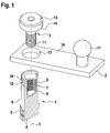
- FIG. 1 shows in the only one FIG. 1 an output shaft of a windshield wiper drive and a means of a fastening screw fixable on the output shaft engine crank for driving a linkage.
- Fig. 1 are an output shaft 1, an engine crank 2 and a mounting screw 3 of an otherwise not shown and known per se, designed as windshield wiper drive, wiper drive shown.
- the windshield wiper drive comprises, in addition to the aforementioned components, an electric motor which rotatively drives a transmission designed in particular as a worm gear. From this transmission, not shown, in turn, the output shaft 1 shown is driven to rotate about its longitudinal central axis L.
- the output shaft in the region of their drawing plane in the lower end 4 has a marginal knurling 5 (positive locking means).
- the output shaft 1 is formed in two parts and includes an elongated, substantially cylindrical shaft portion 6 and a non-rotatably connected to the shaft part 6 female thread part 7 with an internal thread 8.
- the female thread part 7 is a mass-produced, prefabricated component, which is used for the manufacture or assembly of the output shaft 1. This can be dispensed with a machining of the shaft part 6, as would be necessary for a one-piece output shaft 1.
- the internal thread part 7 is positively in a frontal, designed as a blind hole receptacle. 9 of the shaft part 6 was added.
- the rotationally fixed attachment of the internal thread part 7 on the shaft part 6 was carried out during the cold forming process for producing the shaft part shape shown. In particular, during the cold forming, the lower knurling 5 as well as an upper knurling 10 in the plane of the drawing were formed to positively connect the output shaft 1 to the motor crank 2.
- Fig. 1 results, it is in the female thread part 7 is a closed end threaded sleeve.
- a simple thread spiral in the receptacle 9 of the output shaft 1 by form and / or frictional engagement.
- the internal thread 8 of the internal thread part 7 is designed to cooperate with an external thread 11 of the fastening screw 3, which serves for the axial pressing of the motor crank 2 against a circumferential shoulder 12 provided on the outer circumference of the output shaft 1.
- the engine crank 2 For non-rotatably connecting the engine crank 2 and the output shaft 1, the engine crank 2 is slipped with a through hole 13 over the axial end of the output shaft 1 with its upper knurling 10, whereupon the fastening screw 3 is screwed into the internal thread 8 of the female thread part 7.
- the fastening screw 3 passes through the passage opening 13 in the axial direction.
- the mounting screw 3 When fully assembled engine crank 2, the mounting screw 3 is supported with an annular lower head surface 14 of a screw head 15 of the mounting screw 3 on a side facing away from the output shaft 1 flat side 16 in the region radially outside the through hole 13 and acts on the motor crank 2 characterized with an axial contact pressure.
- the upper knurling 10 digs during assembly in the inner circumference of the through hole 13, whereby in addition to the press connection, a positive connection is achieved.
- the engine crank 2 is formed as a flat disc and carries at a distance from the passage opening 13 so at a distance from the longitudinal center axis L of the output shaft 1 a spherical pivot pin 17 for fixing the driven by the engine crank 2, not shown linkage of the windshield wiper drive.
Landscapes
- Engineering & Computer Science (AREA)
- Mechanical Engineering (AREA)
- General Engineering & Computer Science (AREA)
- Connection Of Motors, Electrical Generators, Mechanical Devices, And The Like (AREA)
- Gears, Cams (AREA)
- Shafts, Cranks, Connecting Bars, And Related Bearings (AREA)
- Gear Transmission (AREA)
Description
- Die Erfindung betrifft eine Abtriebswelle für einen Scheibenwischerantrieb, insbesondere für einen Frontscheibenwischerantrieb, gemäß dem Oberbegriff des Anspruchs 1, einen Scheibenwischerantrieb gemäß Anspruch 6 sowie eine Verwendung einer Abtriebswelle gemäß Anspruch 7.
- Bekannte Frontscheibenwischerantriebe umfassen einen Elektromotor, der über ein Schneckengetriebe eine Abtriebswelle rotierend antreibt. An der Abtriebswelle des Scheibenwischerantriebs ist endseitig drehfest eine Kurbel (so genannte Motorkurbel) festgelegt, an der ein Gestänge angelenkt ist. Über das Gestänge werden zwei quer zur Fahrzeuglängsrichtung beabstandete Wischerwellen pendelnd angetrieben, wobei jede Wischerwelle drehfest mit einem einen Wischergummi tragenden Wischerarm verbunden ist. Bei bekannten Scheibenwischerantrieben ist die Motorkurbel mittels einer Befestigungsschraube an der Abtriebswelle festgelegt, wobei ein Außengewinde der Befestigungsschraube mit einem stirnseitig unmittelbar in die einteilige Abtriebswelle eingebrachten Innengewinde zusammenwirkt. Nachteilig bei dem bekannten Scheibenwischerantrieb ist die vergleichsweise aufwändige Fertigung der Abtriebswelle, insbesondere deshalb, weil das Gewinde durch spanende Bearbeitung bei der Herstellung der Abtriebswelle geschnitten wird.
- Die Offenlegungsschrift
GB 2 088 707 A - Die Offenlegungsschrift
DE 102 059 956 A1 zeigt eine Scheibenwischvorrichtung mit mindestens einer Antriebseinrichtung, die mindestens eine Abtriebswelle aufweist, wobei die Abtriebswelle ein Innengewinde umfasst. - Die Patentschrift
US 6,447,404 B1 zeigt einen zweiteiligen Golfschläger, welcher mittels eines Verbindungsteils umfassend zwei miteinander verschraubbare Teile verschraubt werden kann. - Der Erfindung liegt daher die Aufgabe zugrunde, eine einfach fertigbare Abtriebswelle für einen Scheibenwischerantrieb zum Festlegen einer Motorkurbel bereitzustellen. Ferner besteht die Aufgabe darin, einen Scheibenwischerantrieb mit einer entsprechend optimierten Abtriebswelle bereitzustellen.
- Diese Aufgabe wird hinsichtlich der Abtriebswelle mit den Merkmalen des Anspruchs 1 und hinsichtlich des Scheibenwischerantriebs mit den Merkmalen des Anspruchs 8 gelöst. Vorteilhafte Weiterbildungen der Erfindung sind in den Unteransprüchen angegeben. In den Rahmen der Erfindung fallen sämtliche Kombinationen aus zumindest zwei in der Beschreibung, den Ansprüchen und/oder den Figuren offenbarten Merkmalen.
- Der Grundgedanke der Erfindung besteht darin, dass das Innengewinde zum Zusammenwirken der Befestigungsschraube zum Festlegen der Motorkurbel an der Antriebswelle nicht mehr wie im Stand der Technik unmittelbar bei der Herstellung der Abtriebswelle in eine einteilige Abtriebswelle eingebracht wird, sondern stattdessen in einem, insbesondere als Massenartikel erhältlichen, Innengewindeteil vorgesehen ist, welches drehfest an einem langgestreckten Wellenteil der Abtriebswelle festgelegt ist. Anders ausgedrückt ist eine nach dem Konzept der Erfindung ausgebildete Abtriebswelle nicht einteilig, sondern zumindest, vorzugsweise genau, zweiteilig ausgebildet und umfasst ein ein Innengewinde aufweisendes Innengewindeteil, das drehfest mit einem, zumindest näherungsweise zylindrischen, Wellenteil verbunden ist. Durch diese Maßnahme vereinfacht sich die Herstellung der Abtriebswelle, da bei der Formgebung der Abtriebswelle, insbesondere durch Kaltumformen, auf eine separate spanende Bearbeitung zum Einbringen des Innengewindes verzichtet werden kann. Das beim Herstellen der Abtriebswelle zum Einsatz kommende Innengewindeteil kann separat hergestellt oder bezogen werden und bedarf bei der eigentlichen Fertigung bzw. Montage der Abtriebswelle keiner weiteren Bearbeitung. Insgesamt wird durch die Erfindung der eigentliche Herstellungsprozess der Abtriebswelle für einen Scheibenwischerantrieb verkürzt, wodurch die Herstellungskosten minimiert werden.
- Nach einer nicht beanspruchte Ausführungsform kann vorgesehen sein, dass das Innengewindeteil als Gewindespirale ausgebildet ist als Alternative zu der beanspruchte Ausführungsform des Innengewindeteils als einseitig geschlossene Innengewindehülse.
- In Weiterbildung der Erfindung ist mit Vorteil vorgesehen, dass das Innengewindeteil in das Wellenteil eingepresst und/oder eingeformt ist. Das Einpressen und/oder Einformen erfolgt dabei vorzugsweise während einer Kaltumformung eines stangenartigen Elementes zur Herstellung des langgestreckten Wellenteils. Die Formgebung des Wellenteils erfolgt also in einem gemeinsamen Schritt mit dem Festlegen des Innengewindeteils, so dass auf einen separaten Montageschritt verzichtet werden kann.
- Mit Vorteil ist vorgesehen, dass bei der Herstellung des langgestreckten Wellenteils auf eine spanende Bearbeitung vollständig verzichtet wird. Dies kann dadurch realisiert werden, dass das langgestreckte Wellenteil ausschließlich durch Kaltumformen eines länglichen Metallteils (Rohling) hergestellt ist.
- Nach der Erfindung ist das Innengewindeteil derart am langgestreckten Wellenteil angeordnet, dass von einer Stirnseite her in das Innengewinde des Innengewindeteils eine Befestigungsschraube zum Festlegen der Motorkurbel eingeführt und verschraubt werden kann. Hierzu ist das Innengewindeteil in einer stirnseitigen Öffnung (Aufnahme) des Wellenteils angeordnet, wobei die Öffnung nicht als in axialer Richtung durchgehende Öffnung, sondern als Sacklochöffnung ausgebildet ist, um die Robustheit der Abtriebswelle nicht unnötig zu schwächen.
- Besonders zweckmäßig ist eine Ausführungsvariante der Abtriebswelle, bei der das Innengewindeteil und das langgestreckte Wellenteil aus unterschiedlichen Materialien, insbesondere aus unterschiedlichen Stählen, ausgebildet sind, wobei die Materialien entsprechend der Funktionen bzw. Beanspruchungsart. des Innengewindeteils bzw. des langgestreckten Wellenteils gewählt sind. So hat das Innengewindeteil im Wesentlichen die Aufgabe die Befestigungsschraube in axialer Richtung zu fixieren, um auf diese Weise die Motorkurbel axial gegen die Abtriebswelle zu pressen. Dem langgestreckten Wellenteil kommt im Wesentlichen die Aufgabe zu, zum einen ein Drehmoment von dem Getriebe aufzunehmen und an die Motorkurbel weiterzugeben.
- Besonders bevorzugt ist eine Ausführungsform der Abtriebswelle, bei der diese, beispielsweise von einer Rändelung gebildete, Formschlussmittel zum formschlüssigen Verbinden mit einem Abtriebszahnrad eines Getriebes eines Scheibenwischerantriebs aufweist. Es ist auch eine Ausführungsform realisierbar, bei der die Abtriebswelle einteilig mit einem derartigen Abtriebsrad, welches vorzugsweise als Schneckenrad eines Schneckengetriebes ausgebildet ist, ausgeformt ist.
- Die Erfindung führt auch auf einen Scheibenwischerantrieb, insbesondere einen Frontscheibenwischerantrieb, umfassend einen Elektromotor, ein von dem Elektromotor angetriebenes Getriebe sowie eine zuvor beschriebene Abtriebswelle, die mittels des Getriebes um ihre Längsachse in Rotation versetzbar ist. Ferner umfasst der Scheibenwischerantrieb eine drehfest an der Abtriebswelle mittels einer Befestigungsschraube festgelegte Motorkurbel, wobei die Befestigungsschraube mit dem Innengewinde des Innengewindeteils der Abtriebswelle verschraubt ist. Durch die zumindest, vorzugsweise ausschließlich, zweiteilige Ausbildung der Abtriebswelle, umfassend ein langgestrecktes Wellenteil und ein drehfest mit diesem verbundenes Innengewindeteil kann die Herstellung der Abtriebswelle vereinfacht werden, wodurch sich die Herstellung des Scheibenwischerantriebs insgesamt sowie dessen Herstellungskosten minimieren.
- Darüber hinaus führt die Erfindung auch auf eine Verwendung einer mehrteiligen, zuvor beschriebenen Abtriebswelle als Abtriebswelle eines Scheibenwischerantriebs zum rotierenden Antreiben einer Kurbelwelle.
- Weitere Vorteile, Merkmale und Einzelheiten der Erfindung ergeben sich aus der nachfolgenden Beschreibung eines bevorzugten Ausführungsbeispiels sowie anhand der Zeichnung. Diese zeigt in der einzigen
Figur 1 eine Abtriebswelle eines Scheibenwischerantriebs sowie eine mittels einer Befestigungsschraube an der Abtriebswelle festlegbare Motorkurbel zum Antreiben eines Gestänges. - In
Fig. 1 sind eine Abtriebswelle 1, eine Motorkurbel 2 und eine Befestigungsschraube 3 eines ansonsten nicht weiter dargestellten und an sich bekannten, als Frontscheibenwischerantrieb ausgebildeten, Scheibenwischerantriebs gezeigt. Der Scheibenwischerantrieb umfasst neben den vorgenannten Bauelementen einen Elektromotor, der rotierend ein insbesondere als Schneckengetriebe ausgebildetes Getriebe antreibt. Von diesem nicht dargestellten Getriebe wiederum wird die gezeigte Abtriebswelle 1 rotierend um ihre Längsmittelachse L angetrieben. Zum formschlüssigen Verbinden der Abtriebswelle 1 mit einem nicht gezeigten, als Schneckenrad ausgebildeten Abtriebszahnrad des nicht gezeigten Getriebes umfasst die Abtriebswelle im Bereich ihres in der Zeichnungsebene unteren Endes 4 eine randseitige Rändelung 5 (Formschlussmittel). - Wie sich aus
Fig. 1 ergibt, ist die Abtriebswelle 1 zweiteilig ausgebildet und umfasst ein langgestrecktes, im Wesentlichen zylinderförmiges Wellenteil 6 sowie ein drehfest mit dem Wellenteil 6 verbundenes Innengewindeteil 7 mit einem Innengewinde 8. Bei dem Innengewindeteil 7 handelt es sich um ein als Massenprodukt erhältliches, vorgefertigtes Bauteil, was zum Herstellen bzw. zur Montage der Abtriebswelle 1 eingesetzt wird. Hierdurch kann auf eine spanende Bearbeitung des Wellenteils 6, wie sie bei einer einteiligen Abtriebswelle 1 notwendig wäre, verzichtet werden. Das Innengewindeteil 7 ist formschlüssig in einer stirnseitigen, als Sacklochöffnung ausgebildeten Aufnahme 9 des Wellenteils 6 aufgenommen. Die drehfeste Befestigung des Innengewindeteils 7 an dem Wellenteil 6 erfolgte während des Kaltverformungsprozesses zur Herstellung der gezeigten Wellenteilform. Insbesondere wurden während des Kaltverformens die untere Rändelung 5 sowie eine in der Zeichnungsebene obere Rändelung 10 zum formschlüssigen Verbinden der Abtriebswelle 1 mit der Motorkurbel 2 eingeformt. - Wie sich aus
Fig. 1 ergibt, handelt es sich bei dem Innengewindeteil 7 um eine endseitig geschlossene Gewindehülse. Alternativ ist es denkbar, eine einfache Gewindespirale in die Aufnahme 9 der Abtriebswelle 1 durch Form- und/oder Reibschluss zu integrieren. - Das Innengewinde 8 des Innengewindeteils 7 ist zum Zusammenwirken mit einem Außengewinde 11 der Befestigungsschraube 3 ausgebildet, die zum axialen Pressen der Motorkurbel 2 gegen eine am Außenumfang der Abtriebswelle 1 vorgesehene Umfangsschulter 12 dient.
- Zum drehfesten Verbinden der Motorkurbel 2 und der Abtriebswelle 1 wird die Motorkurbel 2 mit einer Durchgangsöffnung 13 über das axiale Ende der Abtriebswelle 1 mit seiner oberen Rändelung 10 gestülpt, woraufhin die Befestigungsschraube 3 in das Innengewinde 8 des Innengewindeteils 7 eingeschraubt wird. Dabei durchsetzt die Befestigungsschraube 3 die Durchgangsöffnung 13 in axialer Richtung. Bei fertig montierter Motorkurbel 2 stützt sich die Befestigungsschraube 3 mit einer ringförmigen Unterkopffläche 14 eines Schraubenkopfes 15 der Befestigungsschraube 3 an einer von der Abtriebswelle 1 abgewandten Flachseite 16 im Bereich radial außerhalb der Durchgangsöffnung 13 ab und beaufschlagt die Motorkurbel 2 dadurch mit einer axialen Anpresskraft. Die obere Rändelung 10 gräbt sich bei der Montage in den Innenumfang der Durchgangsöffnung 13 ein, wodurch zusätzlich zu der Pressverbindung eine formschlüssige Verbindung erzielt wird.
- Wie sich weiter aus
Fig. 1 ergibt, ist die Motorkurbel 2 als Flachscheibe ausgebildet und trägt mit Abstand zu der Durchgangsöffnung 13 also mit Abstand zu der Längsmittelachse L der Abtriebswelle 1 einen kugelförmigen Gelenkzapfen 17 zum Festlegen des von der Motorkurbel 2 anzutreibenden, nicht gezeigten Gestänges des Scheibenwischerantriebs.
Claims (7)
- Abtriebswelle für einen Scheibenwischerantrieb, mit einem Innengewinde (8) zur Aufnahme (9) einer Befestigungsschraube (3) zum Festlegen einer Motorkurbel (2),
wobei,
das Innengewinde (8) in einem Innengewindeteil (7) vorgesehen ist, das drehfest an einem langgestreckten Wellenteil (6) festgelegt ist, wobei das Wellenteil (6) einen, vorzugsweise zylindrischen oder konischen, Rändelabschnitt zum formschlüssigen Festlegen der Motorkurbel (2) aufweist, wobei das Innengewindeteil (7) als einseitig geschlossene innengewindehülse ausgebildet ist, dadurch gekennzeichnet, daß die Innengewindehülse in einer stirnseitigen, als Sacklochöffnung ausgebildeten, Öffnung des Wellenteils (6) angeordnet ist. - Abtriebswelle nach Anspruch 1,
dadurch gekennzeichnet,
dass das Innengewindeteil (7) in das langgestreckte Wellenteil (6), eingepresst und/oder eingeformt ist. - Abtriebswelle nach einem der Ansprüche 1 oder 2,
dadurch gekennzeichnet,
dass das langgestreckte Wellenteil (6) ausschließlich durch Kaltumformen aus einem stangenförmigen Metallteil gebildet ist. - Abtriebswelle nach einem der vorhergehenden Ansprüchen,
dadurch gekennzeichnet,
dass das Innengewindeteil (7) und das langgestreckte Welienteil (6) aus unterschiedlichen Materialien, insbesondere unterschiedlichen Stählen, ausgebildet sind. - Abtriebswelle nach einem der vorhergehenden Ansprüchen,
dadurch gekennzeichnet,
dass die Abtriebswelle (1) Formschlussmittel zum formschlüssigen Verbinden mit einem Abtriebsrad eines Getriebes aufweist. - Scheibenwischerantrieb, insbesondere Frontscheibenwischerantrieb, mit einem ein Elektromotor, einem Getriebe mit einer Abtriebswelle (1) nach einem der vorhergehenden Ansprüche, sowie mit einer Motorkurbel (2), die mittels einer mit dem Innengewinde (8) der Abtriebswelle (1) verschraubten Befestigungsschraube (3) an der Abtriebswelle (1) festgelegt ist.
- Verwendung einer Abtriebswelle (1) nach einem der Ansprüche 1 bis 5 als Abtriebswelle (1) eines Scheibenwischerantriebs zum rotierenden Antreiben einer Motorkurbel (2).
Applications Claiming Priority (3)
| Application Number | Priority Date | Filing Date | Title |
|---|---|---|---|
| DE102008041233 | 2008-08-13 | ||
| DE102008041864A DE102008041864A1 (de) | 2008-08-13 | 2008-09-08 | Abtriebswelle für einen Scheibenwischerantrieb |
| PCT/EP2009/059050 WO2010018042A1 (de) | 2008-08-13 | 2009-07-15 | Abtriebswelle für einen scheibenwischerantrieb |
Publications (2)
| Publication Number | Publication Date |
|---|---|
| EP2323876A1 EP2323876A1 (de) | 2011-05-25 |
| EP2323876B1 true EP2323876B1 (de) | 2016-07-06 |
Family
ID=41528244
Family Applications (1)
| Application Number | Title | Priority Date | Filing Date |
|---|---|---|---|
| EP09780620.2A Not-in-force EP2323876B1 (de) | 2008-08-13 | 2009-07-15 | Abtriebswelle für einen scheibenwischerantrieb |
Country Status (8)
| Country | Link |
|---|---|
| EP (1) | EP2323876B1 (de) |
| JP (1) | JP2011530447A (de) |
| KR (1) | KR20110042308A (de) |
| CN (1) | CN102119093A (de) |
| BR (1) | BRPI0918895A2 (de) |
| DE (1) | DE102008041864A1 (de) |
| RU (1) | RU2011109083A (de) |
| WO (1) | WO2010018042A1 (de) |
Families Citing this family (1)
| Publication number | Priority date | Publication date | Assignee | Title |
|---|---|---|---|---|
| FR3039111B1 (fr) * | 2015-07-24 | 2017-07-28 | Valeo Systemes Dessuyage | Organe de sortie, dispositif de motorisation pour l’entrainement d’au moins un bras d’essuie-glace de vehicule automobile et procede de fabrication d’un organe de sortie |
Family Cites Families (5)
| Publication number | Priority date | Publication date | Assignee | Title |
|---|---|---|---|---|
| DE3045504A1 (de) * | 1980-12-03 | 1982-07-01 | SWF-Spezialfabrik für Autozubehör Gustav Rau GmbH, 7120 Bietigheim-Bissingen | Wischanlage fuer kraftfahrzeuge |
| US6447404B1 (en) * | 2000-09-05 | 2002-09-10 | Kurt C. Wilbur | Separable-shaft golf club |
| DE10259956B4 (de) * | 2002-12-20 | 2014-11-13 | Robert Bosch Gmbh | Scheibenwischvorrichtung, insbesondere für ein Kraftfahrzeug |
| DE20315460U1 (de) * | 2003-10-08 | 2005-02-17 | Liebherr-Hydraulikbagger Gmbh | Lagerbolzenverbindung |
| DE102007027662B4 (de) * | 2007-06-15 | 2017-08-24 | Robert Bosch Gmbh | Scheibenwischervorrichtung |
-
2008
- 2008-09-08 DE DE102008041864A patent/DE102008041864A1/de not_active Ceased
-
2009
- 2009-07-15 BR BRPI0918895A patent/BRPI0918895A2/pt not_active IP Right Cessation
- 2009-07-15 KR KR1020117003218A patent/KR20110042308A/ko not_active Withdrawn
- 2009-07-15 RU RU2011109083/11A patent/RU2011109083A/ru not_active Application Discontinuation
- 2009-07-15 EP EP09780620.2A patent/EP2323876B1/de not_active Not-in-force
- 2009-07-15 WO PCT/EP2009/059050 patent/WO2010018042A1/de not_active Ceased
- 2009-07-15 CN CN2009801312417A patent/CN102119093A/zh active Pending
- 2009-07-15 JP JP2011522455A patent/JP2011530447A/ja active Pending
Also Published As
| Publication number | Publication date |
|---|---|
| DE102008041864A1 (de) | 2010-02-18 |
| CN102119093A (zh) | 2011-07-06 |
| KR20110042308A (ko) | 2011-04-26 |
| WO2010018042A1 (de) | 2010-02-18 |
| RU2011109083A (ru) | 2012-09-20 |
| BRPI0918895A2 (pt) | 2015-12-01 |
| JP2011530447A (ja) | 2011-12-22 |
| EP2323876A1 (de) | 2011-05-25 |
Similar Documents
| Publication | Publication Date | Title |
|---|---|---|
| EP2229300B1 (de) | Scheibenwischerantrieb | |
| EP2499395B1 (de) | Getriebeantriebseinheit | |
| DE3045504A1 (de) | Wischanlage fuer kraftfahrzeuge | |
| WO1993001027A1 (de) | Bohrhammer | |
| DE102006042322A1 (de) | Scheibenwischeranlage mit einem Scheibenwischerantrieb, insbesondere für einen Heckscheibenwischer eines Kraftfahrzeugs mit einer modular austauschbaren Getriebeanordnung | |
| DE102006027345B4 (de) | Wischanlage für Fahrzeugscheiben | |
| EP2318735B1 (de) | Getriebe-antriebseinheit | |
| EP2323876A1 (de) | Abtriebswelle für einen scheibenwischerantrieb | |
| EP2815931A1 (de) | Scheibenwischermotor | |
| EP1444118B1 (de) | Scheibenwischvorrichtung, insbesondere für ein kraftfahrzeug | |
| DE10259956B4 (de) | Scheibenwischvorrichtung, insbesondere für ein Kraftfahrzeug | |
| EP2147837A1 (de) | Scheibenwischerantrieb | |
| DE102008054746B4 (de) | Scheibenwischvorrichtung, insbesondere für eine Heckscheibe eines Kraftfahrzeugs | |
| DE19639593B4 (de) | Wischervorrichtung | |
| EP2127054A1 (de) | Elektromotorische antriebseinheit, insbesondere für scheibenwischer von fahrzeugen | |
| EP1480859B1 (de) | Scheibenwischvorrichtung, insbesondere für ein kraftfahrzeug | |
| DE102008040703B4 (de) | Scheibenwischerantrieb sowie Bausatz für einen Scheibenwischerantrieb | |
| DE102008040695A1 (de) | Abtriebswelle-Wischerarm-Verbindung sowie Scheibenwischerantrieb | |
| DE102018204270A1 (de) | Spindelantrieb und Komfortantrieb mit einem Spindelantrieb | |
| EP2493730B1 (de) | Scheibenwischvorrichtung in einem fahrzeug | |
| DE202007009492U1 (de) | Welle-Nabe-Verbindung mit Exzenterspannhülse | |
| EP2032400A1 (de) | Elektromotorischer wischerantrieb | |
| DE102005031263A1 (de) | Gelenkbeschlag mit Keilspielausgleich | |
| EP1288088B1 (de) | Wischeranlage mit einer Platine | |
| DE102006017930A1 (de) | Getriebe-Antriebseinheit mit einem Lagerbolzen, sowie Verfahren zu dessen Herstellung |
Legal Events
| Date | Code | Title | Description |
|---|---|---|---|
| PUAI | Public reference made under article 153(3) epc to a published international application that has entered the european phase |
Free format text: ORIGINAL CODE: 0009012 |
|
| 17P | Request for examination filed |
Effective date: 20110314 |
|
| AK | Designated contracting states |
Kind code of ref document: A1 Designated state(s): AT BE BG CH CY CZ DE DK EE ES FI FR GB GR HR HU IE IS IT LI LT LU LV MC MK MT NL NO PL PT RO SE SI SK SM TR |
|
| AX | Request for extension of the european patent |
Extension state: AL BA RS |
|
| DAX | Request for extension of the european patent (deleted) | ||
| 17Q | First examination report despatched |
Effective date: 20121022 |
|
| GRAP | Despatch of communication of intention to grant a patent |
Free format text: ORIGINAL CODE: EPIDOSNIGR1 |
|
| INTG | Intention to grant announced |
Effective date: 20160204 |
|
| INTG | Intention to grant announced |
Effective date: 20160209 |
|
| GRAS | Grant fee paid |
Free format text: ORIGINAL CODE: EPIDOSNIGR3 |
|
| GRAA | (expected) grant |
Free format text: ORIGINAL CODE: 0009210 |
|
| AK | Designated contracting states |
Kind code of ref document: B1 Designated state(s): AT BE BG CH CY CZ DE DK EE ES FI FR GB GR HR HU IE IS IT LI LT LU LV MC MK MT NL NO PL PT RO SE SI SK SM TR |
|
| REG | Reference to a national code |
Ref country code: GB Ref legal event code: FG4D Free format text: NOT ENGLISH |
|
| REG | Reference to a national code |
Ref country code: AT Ref legal event code: REF Ref document number: 810458 Country of ref document: AT Kind code of ref document: T Effective date: 20160715 Ref country code: CH Ref legal event code: EP |
|
| REG | Reference to a national code |
Ref country code: IE Ref legal event code: FG4D Free format text: LANGUAGE OF EP DOCUMENT: GERMAN |
|
| REG | Reference to a national code |
Ref country code: DE Ref legal event code: R096 Ref document number: 502009012792 Country of ref document: DE |
|
| REG | Reference to a national code |
Ref country code: FR Ref legal event code: PLFP Year of fee payment: 8 |
|
| PGFP | Annual fee paid to national office [announced via postgrant information from national office to epo] |
Ref country code: DE Payment date: 20160927 Year of fee payment: 8 |
|
| REG | Reference to a national code |
Ref country code: NL Ref legal event code: MP Effective date: 20160706 |
|
| REG | Reference to a national code |
Ref country code: LT Ref legal event code: MG4D |
|
| PGFP | Annual fee paid to national office [announced via postgrant information from national office to epo] |
Ref country code: FR Payment date: 20160825 Year of fee payment: 8 |
|
| PG25 | Lapsed in a contracting state [announced via postgrant information from national office to epo] |
Ref country code: BE Free format text: LAPSE BECAUSE OF NON-PAYMENT OF DUE FEES Effective date: 20160731 |
|
| PG25 | Lapsed in a contracting state [announced via postgrant information from national office to epo] |
Ref country code: IT Free format text: LAPSE BECAUSE OF FAILURE TO SUBMIT A TRANSLATION OF THE DESCRIPTION OR TO PAY THE FEE WITHIN THE PRESCRIBED TIME-LIMIT Effective date: 20160706 Ref country code: IS Free format text: LAPSE BECAUSE OF FAILURE TO SUBMIT A TRANSLATION OF THE DESCRIPTION OR TO PAY THE FEE WITHIN THE PRESCRIBED TIME-LIMIT Effective date: 20161106 Ref country code: NL Free format text: LAPSE BECAUSE OF FAILURE TO SUBMIT A TRANSLATION OF THE DESCRIPTION OR TO PAY THE FEE WITHIN THE PRESCRIBED TIME-LIMIT Effective date: 20160706 Ref country code: NO Free format text: LAPSE BECAUSE OF FAILURE TO SUBMIT A TRANSLATION OF THE DESCRIPTION OR TO PAY THE FEE WITHIN THE PRESCRIBED TIME-LIMIT Effective date: 20161006 Ref country code: FI Free format text: LAPSE BECAUSE OF FAILURE TO SUBMIT A TRANSLATION OF THE DESCRIPTION OR TO PAY THE FEE WITHIN THE PRESCRIBED TIME-LIMIT Effective date: 20160706 Ref country code: LT Free format text: LAPSE BECAUSE OF FAILURE TO SUBMIT A TRANSLATION OF THE DESCRIPTION OR TO PAY THE FEE WITHIN THE PRESCRIBED TIME-LIMIT Effective date: 20160706 Ref country code: HR Free format text: LAPSE BECAUSE OF FAILURE TO SUBMIT A TRANSLATION OF THE DESCRIPTION OR TO PAY THE FEE WITHIN THE PRESCRIBED TIME-LIMIT Effective date: 20160706 |
|
| PG25 | Lapsed in a contracting state [announced via postgrant information from national office to epo] |
Ref country code: SE Free format text: LAPSE BECAUSE OF FAILURE TO SUBMIT A TRANSLATION OF THE DESCRIPTION OR TO PAY THE FEE WITHIN THE PRESCRIBED TIME-LIMIT Effective date: 20160706 Ref country code: ES Free format text: LAPSE BECAUSE OF FAILURE TO SUBMIT A TRANSLATION OF THE DESCRIPTION OR TO PAY THE FEE WITHIN THE PRESCRIBED TIME-LIMIT Effective date: 20160706 Ref country code: PL Free format text: LAPSE BECAUSE OF FAILURE TO SUBMIT A TRANSLATION OF THE DESCRIPTION OR TO PAY THE FEE WITHIN THE PRESCRIBED TIME-LIMIT Effective date: 20160706 Ref country code: LV Free format text: LAPSE BECAUSE OF FAILURE TO SUBMIT A TRANSLATION OF THE DESCRIPTION OR TO PAY THE FEE WITHIN THE PRESCRIBED TIME-LIMIT Effective date: 20160706 Ref country code: GR Free format text: LAPSE BECAUSE OF FAILURE TO SUBMIT A TRANSLATION OF THE DESCRIPTION OR TO PAY THE FEE WITHIN THE PRESCRIBED TIME-LIMIT Effective date: 20161007 Ref country code: PT Free format text: LAPSE BECAUSE OF FAILURE TO SUBMIT A TRANSLATION OF THE DESCRIPTION OR TO PAY THE FEE WITHIN THE PRESCRIBED TIME-LIMIT Effective date: 20161107 |
|
| REG | Reference to a national code |
Ref country code: CH Ref legal event code: PL |
|
| REG | Reference to a national code |
Ref country code: DE Ref legal event code: R097 Ref document number: 502009012792 Country of ref document: DE |
|
| PG25 | Lapsed in a contracting state [announced via postgrant information from national office to epo] |
Ref country code: EE Free format text: LAPSE BECAUSE OF FAILURE TO SUBMIT A TRANSLATION OF THE DESCRIPTION OR TO PAY THE FEE WITHIN THE PRESCRIBED TIME-LIMIT Effective date: 20160706 Ref country code: LI Free format text: LAPSE BECAUSE OF NON-PAYMENT OF DUE FEES Effective date: 20160731 Ref country code: RO Free format text: LAPSE BECAUSE OF FAILURE TO SUBMIT A TRANSLATION OF THE DESCRIPTION OR TO PAY THE FEE WITHIN THE PRESCRIBED TIME-LIMIT Effective date: 20160706 Ref country code: MC Free format text: LAPSE BECAUSE OF FAILURE TO SUBMIT A TRANSLATION OF THE DESCRIPTION OR TO PAY THE FEE WITHIN THE PRESCRIBED TIME-LIMIT Effective date: 20160706 Ref country code: CH Free format text: LAPSE BECAUSE OF NON-PAYMENT OF DUE FEES Effective date: 20160731 |
|
| REG | Reference to a national code |
Ref country code: IE Ref legal event code: MM4A |
|
| PLBE | No opposition filed within time limit |
Free format text: ORIGINAL CODE: 0009261 |
|
| STAA | Information on the status of an ep patent application or granted ep patent |
Free format text: STATUS: NO OPPOSITION FILED WITHIN TIME LIMIT |
|
| PG25 | Lapsed in a contracting state [announced via postgrant information from national office to epo] |
Ref country code: CZ Free format text: LAPSE BECAUSE OF FAILURE TO SUBMIT A TRANSLATION OF THE DESCRIPTION OR TO PAY THE FEE WITHIN THE PRESCRIBED TIME-LIMIT Effective date: 20160706 Ref country code: BG Free format text: LAPSE BECAUSE OF FAILURE TO SUBMIT A TRANSLATION OF THE DESCRIPTION OR TO PAY THE FEE WITHIN THE PRESCRIBED TIME-LIMIT Effective date: 20161006 Ref country code: SM Free format text: LAPSE BECAUSE OF FAILURE TO SUBMIT A TRANSLATION OF THE DESCRIPTION OR TO PAY THE FEE WITHIN THE PRESCRIBED TIME-LIMIT Effective date: 20160706 Ref country code: SK Free format text: LAPSE BECAUSE OF FAILURE TO SUBMIT A TRANSLATION OF THE DESCRIPTION OR TO PAY THE FEE WITHIN THE PRESCRIBED TIME-LIMIT Effective date: 20160706 Ref country code: DK Free format text: LAPSE BECAUSE OF FAILURE TO SUBMIT A TRANSLATION OF THE DESCRIPTION OR TO PAY THE FEE WITHIN THE PRESCRIBED TIME-LIMIT Effective date: 20160706 |
|
| 26N | No opposition filed |
Effective date: 20170407 |
|
| GBPC | Gb: european patent ceased through non-payment of renewal fee |
Effective date: 20161006 |
|
| PG25 | Lapsed in a contracting state [announced via postgrant information from national office to epo] |
Ref country code: GB Free format text: LAPSE BECAUSE OF NON-PAYMENT OF DUE FEES Effective date: 20161006 Ref country code: IE Free format text: LAPSE BECAUSE OF NON-PAYMENT OF DUE FEES Effective date: 20160715 |
|
| PG25 | Lapsed in a contracting state [announced via postgrant information from national office to epo] |
Ref country code: SI Free format text: LAPSE BECAUSE OF FAILURE TO SUBMIT A TRANSLATION OF THE DESCRIPTION OR TO PAY THE FEE WITHIN THE PRESCRIBED TIME-LIMIT Effective date: 20160706 Ref country code: LU Free format text: LAPSE BECAUSE OF NON-PAYMENT OF DUE FEES Effective date: 20160715 |
|
| REG | Reference to a national code |
Ref country code: AT Ref legal event code: MM01 Ref document number: 810458 Country of ref document: AT Kind code of ref document: T Effective date: 20160715 |
|
| PG25 | Lapsed in a contracting state [announced via postgrant information from national office to epo] |
Ref country code: AT Free format text: LAPSE BECAUSE OF NON-PAYMENT OF DUE FEES Effective date: 20160715 |
|
| REG | Reference to a national code |
Ref country code: DE Ref legal event code: R119 Ref document number: 502009012792 Country of ref document: DE |
|
| REG | Reference to a national code |
Ref country code: FR Ref legal event code: ST Effective date: 20180330 |
|
| PG25 | Lapsed in a contracting state [announced via postgrant information from national office to epo] |
Ref country code: DE Free format text: LAPSE BECAUSE OF NON-PAYMENT OF DUE FEES Effective date: 20180201 |
|
| PG25 | Lapsed in a contracting state [announced via postgrant information from national office to epo] |
Ref country code: HU Free format text: LAPSE BECAUSE OF FAILURE TO SUBMIT A TRANSLATION OF THE DESCRIPTION OR TO PAY THE FEE WITHIN THE PRESCRIBED TIME-LIMIT; INVALID AB INITIO Effective date: 20090715 Ref country code: FR Free format text: LAPSE BECAUSE OF NON-PAYMENT OF DUE FEES Effective date: 20170731 Ref country code: CY Free format text: LAPSE BECAUSE OF FAILURE TO SUBMIT A TRANSLATION OF THE DESCRIPTION OR TO PAY THE FEE WITHIN THE PRESCRIBED TIME-LIMIT Effective date: 20160706 |
|
| PG25 | Lapsed in a contracting state [announced via postgrant information from national office to epo] |
Ref country code: MK Free format text: LAPSE BECAUSE OF FAILURE TO SUBMIT A TRANSLATION OF THE DESCRIPTION OR TO PAY THE FEE WITHIN THE PRESCRIBED TIME-LIMIT Effective date: 20160706 Ref country code: TR Free format text: LAPSE BECAUSE OF FAILURE TO SUBMIT A TRANSLATION OF THE DESCRIPTION OR TO PAY THE FEE WITHIN THE PRESCRIBED TIME-LIMIT Effective date: 20160706 Ref country code: MT Free format text: LAPSE BECAUSE OF FAILURE TO SUBMIT A TRANSLATION OF THE DESCRIPTION OR TO PAY THE FEE WITHIN THE PRESCRIBED TIME-LIMIT Effective date: 20160706 |