EP2322403A2 - Automatic coupling for railway vehicles with side buffers - Google Patents
Automatic coupling for railway vehicles with side buffers Download PDFInfo
- Publication number
- EP2322403A2 EP2322403A2 EP10014549A EP10014549A EP2322403A2 EP 2322403 A2 EP2322403 A2 EP 2322403A2 EP 10014549 A EP10014549 A EP 10014549A EP 10014549 A EP10014549 A EP 10014549A EP 2322403 A2 EP2322403 A2 EP 2322403A2
- Authority
- EP
- European Patent Office
- Prior art keywords
- coupling
- cylinder
- head
- chamber
- clutch
- Prior art date
- Legal status (The legal status is an assumption and is not a legal conclusion. Google has not performed a legal analysis and makes no representation as to the accuracy of the status listed.)
- Granted
Links
Images

Classifications
-
- B—PERFORMING OPERATIONS; TRANSPORTING
- B61—RAILWAYS
- B61G—COUPLINGS; DRAUGHT AND BUFFING APPLIANCES
- B61G9/00—Draw-gear
- B61G9/20—Details; Accessories
- B61G9/24—Linkages between draw-bar and framework
-
- B—PERFORMING OPERATIONS; TRANSPORTING
- B61—RAILWAYS
- B61G—COUPLINGS; DRAUGHT AND BUFFING APPLIANCES
- B61G7/00—Details or accessories
- B61G7/08—Adjustable coupling heads
Definitions
- the invention relates to an automatic coupling for rail vehicles with side buffers for receiving pressure forces, with coupling halves, each having on the one hand a coupling head and on the other hand connected to a pulling device for transmitting the tensile forces on the vehicle body.
- the invention has for its object to provide a coupling for rail vehicles of the type mentioned, with which the coupling process automatically, quickly, safely, with low impact energy and relatively small constructive structure is feasible.
- the coupling head and the traction device is a free-lifting device with an axially displaceable pneumatic cylinder is mounted, which is frontally attached to the coupling head and the piston is connected to the drawbar of the traction device, wherein in the uncoupled state of the coupling head occupies a defined position by aerating the cylinder and during the coupling process, the required counterpressure counteracts, while after the clutch by venting the cylinder, a powerless free lift of the clutch is generated, which ensures the operation of the clutch as a pure traction coupling.
- the coupling according to the invention makes it possible to carry out an automatic coupling operation on straight or curved paths with or without a gradient, because it is able to eliminate the interference of the buffers during the coupling process.
- it causes the clutch in the coupled state moves freely in the pressure direction in the area of the maximum buffer spring travel and thus initiates no significant pressure forces in the vehicles, which reinforces the box structure might require.
- the free-lift device also allows the coupling of vehicles with low impact speeds, because the pneumatic cylinder can hold the necessary back pressure at a low level of force in the applied state.
- the invention further provides that the coupling plane of the coupling is arranged lying behind the buffer plane by an amount dependent on the tension between buffers and pulling device.
- the coupling plane is adjustable according to the invention as a function of the bracing force or (pre) adjustable. The latter can be changed step by step by inserting spacers in the drawbars. As a result, the coupling tension is adjustable to minimize the jerking movements in the longitudinal direction of the drawstring.
- the invention also provides that the pneumatic cylinder has a front chamber which can be acted upon by compressed air and a rear chamber which can be acted upon with hydraulic oil, the coupling head being pushed into a position in front of the buffer level when the front chamber is acted upon and retracted when the rear chamber is acted upon and in the rear chamber Dome position is braced, after the clutch, the venting of the front chamber ensures the power-free free travel of the clutch, while the loading of the rear chamber maintains the preload length of the clutch. In this way, the influence of the page buffer on the dome operation is largely reduced or even eliminated.
- the front cylinder chamber is pressurized with compressed air from the feed line of the vehicle, while the rear cylinder chamber is supplied with hydraulic oil from a piston carrier attached to the head carrier.
- a check valve is arranged between the rear cylinder chamber and the piston accumulator, which is closed as soon as the tensile force exceeds the clamping force of the clutch.
- the inventive design of the traction device as a pneumatic / hydraulic device makes it possible to control the coupling process conveniently with a multi-way valve, which is useful for automatic operation.
- the invention further provides that the traction device is provided with a height support and a centering, wherein the height support is formed by a fixed to the head support of the vehicle body and supported on rubber springs Traverse, while the centering is integrated in the Traverse and the coupling head in the dome ready Holds position or leads him back into this.
- the support height of the free lift device can preferably be adjusted.
- Coupling 1 shown consists of two identically designed coupling halves 2, 3, each composed of a coupling head 4, a pulling device 5 (change generally) and an intermediate piston / cylinder unit 14, 15 as a clamping device.
- the coupling halves 2, 3 are arranged centrally between two side buffers 7, 8 in the head carrier 9 of the respective vehicle body.
- the side buffers 7, 8 are known to have the function to absorb pressure forces and to initiate the headgear of the vehicle boxes.
- the vehicles are on a winding track.
- the side buffers are effective on one side during the coupling process.
- the coupling head 4 and the pulling device 5 are conventional construction and are therefore not described in detail below.
- the traction device 5 is known to have the task to initiate the tensile forces occurring during driving in the vehicle body. For this she is with a Tie rod 10 is provided, which is hinged to a bolt 11 arranged in the vehicle body. At this a drawbar 12 is hinged with a spring set 13.
- piston / cylinder unit is assigned a free-lifting device 6, wherein the cylinder 14 is fixed to the front side of the coupling head 4 and the piston 15 is connected to the drawbar 10 of the pulling device 5.
- piston 15 By the piston 15 a pressurizable with compressed air chamber 16 is defined in the cylinder 14, which is fed via the compressed air feed line 17 of the vehicle.
- Each coupling half 2 or 3 is supported on the head support 9 with a height support 18. This is formed by a supported on elastic elements, such as hollow rubber springs 19, Traverse 20, which is suspended on the head support 9 with a bracket 21.
- a centering center 22 is integrated, which engages under the cylinder 14 of the free-lifting device and holds the coupling half 2 and 3 in the clutch-ready position or leads back into this.
- the cylinder 14 is axially displaceable in the centering center 22. It can also be deflected together with the piston 15 and the pull rod 10 by a small angle, wherein the steering axis coincides with the central axis of the pin 11.
- the height of the coupling is adjustable with the height support 18 to accommodate the design features of the vehicles to be coupled.
- the coupling halves 2, 3 are installed so that the coupling plane of the coupling head 4 is disposed in the uncoupled state with a defined amount e in front of the plane of the clutch in the clamped state, while in the coupled state is their coupling plane behind the buffer plane by an amount d , of the depends on the respectively set clamping force.
- the amount d is selected in practice so that the biasing force is substantially the same as that of the screw coupling so that it does not cause large jerking movements in the longitudinal direction of the train in operation.
- the buffer bias can be adjusted step by step by inserting spacers in the pulling device 5.
- the cylinder 14 In the uncoupled or ready for coupling state, the cylinder 14 is supplied with compressed air from the feed line 17 and the chamber 16 acted upon. As a result, the cylinder 14 can advance the coupling head 4 and keep the coupling in a defined position in the uncoupled state: In addition, this ensures that the coupling head 4 opposes the necessary counterpressure force during the coupling process.
- the air cushion in the chamber 16 acts as an air spring, if during the dome operation, the pressure force is too great by the impact speed of the vehicles.
- the chamber 16 is vented, so that the clutch can perform a powerless free lift while driving. This ensures that it only uses the vehicles during operation with tensile forces that correspond to conventional screw couplings. This makes it possible to install the inventive coupling in existing rail vehicles without reinforcing the vehicle body.
- the free lift of the clutch is released during the coupling process by the clutch is pneumatically brought by applying the chamber 16 in the front stop of the free lift.
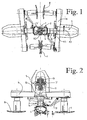
- FIG. 3 to FIG. 5 differs from the basic version Fig. 2 in that in it the cylinder 14 is provided with a one-piece front chamber 24 and a two-part rear chamber 25, wherein the front chamber 24 with compressed air and the rear chamber 25 can be acted upon with hydraulic oil.
- the supply of the cylinder 14 with compressed air as well as the drive means for the hydraulic oil via the compressed air supply line 17 of the vehicle.
- a piston accumulator 26 is provided on the head carrier 9.
- the coupling head 4 By applying pressure to the front chamber 24 with compressed air, the coupling head 4 is advanced over the abutting surface of the buffers (FIG. Fig. 3 ). The coupling head 4 is thus pneumatically extended in front of the buffer layer. This largely eliminates the influence of the buffers on the dome operation. In this way, it is possible to perform the coupling process even in tight curves without large deflection of the page buffer.
- the admission of the front chamber 24 is maintained, which ensures that the coupling head 4 can muster the necessary counter-pressure force when Kuppein.
- hydraulic oil is forced into the rear chamber 25, whereby the clutch is retracted and clamped with the required force ( Fig. 4 ).
- the front chamber 24 is vented, thus ensuring the powerless free lift of the clutch.
- the rear chamber 25 remains filled with oil, which in turn ensures the preload length of the coupling ( Fig. 5 ).
- the rear chamber 25 is closed by a check valve 27.
- This causes the preload length of the clutch to be held and the spring 12 of the traction device 5 to be tensioned under the influence of the drawbar 12.
- the coupling can transmit high tensile forces of the order of magnitude of up to about 1000 kN.
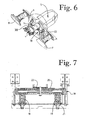
- the arrangement of the check valve 27 is in the circuit diagram according to Fig. 8 illustrated schematically. As can be seen there, the control of the coupling process by means of a 5/2 way valve 28 is performed. Such a simple control is very suitable for the automatic operation of the clutch.
- the free-lift device has the effect that the traction coupling can automatically and freely shorten when the buffers are compressed. It can move freely in the coupled state in the pressure direction in the area of the maximum buffer spring travel.
- the tensile force is introduced into the vehicles via the bolts 11.
- the coupling forms a stretched line between the pivot points of the tie rods 10 in the center axes of these bolts.
- the kinematic behavior of the coupling is comparable to that of a conventional screw coupling.
- the towing device 5 of the counter-coupling In order for the coupling process to take place safely, the towing device 5 of the counter-coupling must oppose a force which in practice may amount to approximately 40 kN.
- a different clamping device between the coupling head 4 and the pulling device 5 may be provided.
- a cylinder 54 and a therein by means of a spindle motor with a spindle 56 longitudinally adjustable piston is provided inside the cylinder 54.
- a formed with compressed air chamber 57 Inside the cylinder 54 is a formed with compressed air chamber 57, wherein the coupling head 4 is pushed upon exposure of the front chamber 57 in a provision with its coupling plane in front of the buffer layer, analogous to that in Fig. 2 is illustrated.
- the coupling head 4 can be brought into the desired starting position and then the coupling can be performed with the necessary counter-pressure force and also the tensile force in the coupled state.
Abstract
Description
Die Erfindung betrifft eine automatische Kupplung für Schienenfahrzeuge mit Seitenpuffern zur Aufnahme von Druckkräften, mit Kupplungshälften, die jeweils einerseits einen Kupplungskopf aufweisen und andererseits mit einer Zugeinrichtung zur Übertragung der Zugkräfte auf den Fahrzeugkasten verbunden sind.The invention relates to an automatic coupling for rail vehicles with side buffers for receiving pressure forces, with coupling halves, each having on the one hand a coupling head and on the other hand connected to a pulling device for transmitting the tensile forces on the vehicle body.
Schienenfahrzeuge dieser Art werden bekanntlich in Personen- oder Güterzügen eingesetzt, die sowohl auf geraden als auch auf kurvigen Strecken mit Gefälle fahren sollen. Das bringt mit sich, dass der Kupplungsvorgang gegebenenfalls auch in kurvigen Streckenbereichen ohne oder mit Gefälle stattfindet. Die Züge werden in der Regel mit Schraubenkupplungen ausgerüstet, die mit Gewindestangen mit Links- und Rechtsgewinde versehen sind. Derartige Kupplungen müssen aber von Hand betätigt werden. Sie sind daher hinsichtlich ihrer Handhabung zeitaufwendig und auch nicht ungefährlich für die sie bedienende Person.Railway vehicles of this type are known to be used in passenger or freight trains, which should travel on both straight and curved roads with gradients. This implies that the coupling process, if necessary, even in curvy sections without or with gradients. The trains are usually equipped with screw couplings, which are provided with threaded rods with left and right-hand thread. But such couplings must be operated by hand. They are therefore time-consuming in terms of handling and also not dangerous for the person serving them.
Der Erfindung liegt die Aufgabe zugrunde, eine Kupplung für Schienenfahrzeuge der eingangs genannten Art zu schaffen, mit welcher der Kupplungsvorgang automatisch, schnell, sicher, mit geringer Stossenergie und mit verhältnismässig kleinem konstruktivem Aufbau durchführbar ist.The invention has for its object to provide a coupling for rail vehicles of the type mentioned, with which the coupling process automatically, quickly, safely, with low impact energy and relatively small constructive structure is feasible.
Diese Aufgabe wird erfindungsgemäss nach Anspruch 1 gelöst.This object is achieved according to claim 1.
Sehr vorteilhaft ist dem Kupplungskopf und der Zugeinrichtung eine Freihubvorrichtung mit einem axial verschiebbaren Pneumatikzylinder eingebaut ist, der stirnseitig am Kupplungskopf befestigt ist und dessen Kolben mit der Zugstange der Zugeinrichtung verbunden ist, wobei im ungekuppelten Zustand der Kupplungskopf durch Belüften des Zylinder eine definierte Stellung einnimmt und beim Kupplungsvorgang die erforderliche Gegendruckkraft entgegenbringt, während nach erfolgter Kupplung durch Entlüften des Zylinders ein kraftloser Freihub der Kupplung erzeugt wird, der den Betrieb der Kupplung als reine Zugkupplung sicherstellt.Very advantageous is the coupling head and the traction device is a free-lifting device with an axially displaceable pneumatic cylinder is mounted, which is frontally attached to the coupling head and the piston is connected to the drawbar of the traction device, wherein in the uncoupled state of the coupling head occupies a defined position by aerating the cylinder and during the coupling process, the required counterpressure counteracts, while after the clutch by venting the cylinder, a powerless free lift of the clutch is generated, which ensures the operation of the clutch as a pure traction coupling.
Die erfindungsgemässe Kupplung ermöglicht die Durchführung eines automatischen Kuppelvorgangs auf geraden oder kurvigen Strecken mit oder ohne Gefälle, weil sie in der Lage ist, die Störwirkung der Puffer beim Kuppelvorgang zu eliminieren. Ausserdem bewirkt sie, dass die Kupplung im gekuppelten Zustand sich in Druckrichtung im Bereich der maximalen Pufferfederwege frei bewegt und somit keine nennenswerten Druckkräfte in die Fahrzeuge einleitet, die eine Verstärkung der Kastenstruktur erfordern könnten. Die Freihubvorrichtung ermöglicht zudem das Ankuppeln der Fahrzeuge mit kleinen Aufprallgeschwindigkeiten, weil der Pneumatikzylinder im beaufschlagten Zustand den notwendigen Gegendruck auf einem tiefen Kraftniveau halten kann.The coupling according to the invention makes it possible to carry out an automatic coupling operation on straight or curved paths with or without a gradient, because it is able to eliminate the interference of the buffers during the coupling process. In addition, it causes the clutch in the coupled state moves freely in the pressure direction in the area of the maximum buffer spring travel and thus initiates no significant pressure forces in the vehicles, which reinforces the box structure might require. The free-lift device also allows the coupling of vehicles with low impact speeds, because the pneumatic cylinder can hold the necessary back pressure at a low level of force in the applied state.
Die Erfindung sieht ferner vor, dass die Kupplungsebene der Kupplung um einen von der Verspannung zwischen Puffern und Zugeinrichtung abhängigen Betrag hinter der Pufferebene liegend angeordnet ist. Die Kupplungsebene ist erfindungsgemäss in Abhängigkeit von der Verspannkraft justierbar bzw. (vor)einstellbar. Letztere kann stufenweise durch Einlegen von Distanzscheiben in den Zugeinrichtungen verändert werden. Dadurch ist auch die Kupplungsverspannung einstellbar, um die Ruckbewegungen in Längsrichtung des Zugverbands zu minimieren.The invention further provides that the coupling plane of the coupling is arranged lying behind the buffer plane by an amount dependent on the tension between buffers and pulling device. The coupling plane is adjustable according to the invention as a function of the bracing force or (pre) adjustable. The latter can be changed step by step by inserting spacers in the drawbars. As a result, the coupling tension is adjustable to minimize the jerking movements in the longitudinal direction of the drawstring.
Die Erfindung sieht ausserdem vor, dass der Pneumatikzylinder eine mit Druckluft beaufschlagbare vordere Kammer und eine mit Hydrauliköl beaufschlagbare hintere Kammer aufweist, wobei der Kupplungskopf bei Beaufschlagung der vorderen Kammer in eine Bereitstellung vor die Pufferebene geschoben wird und bei Beaufschlagung der hinteren Kammer zurückgezogen und in der Kuppelstellung verspannt wird, wobei nach erfolgter Kupplung die Entlüftung der vorderen Kammer den -kraftlosen Freihub der Kupplung sicherstellt, während die Beaufschlagung der hinteren Kammer die Vorspannlänge der Kupplung aufrechterhält. Auf diese Weise wird der Einfluss der Seitenpuffer auf den Kuppelvorgang weitgehend reduziert oder sogar eliminiert.The invention also provides that the pneumatic cylinder has a front chamber which can be acted upon by compressed air and a rear chamber which can be acted upon with hydraulic oil, the coupling head being pushed into a position in front of the buffer level when the front chamber is acted upon and retracted when the rear chamber is acted upon and in the rear chamber Dome position is braced, after the clutch, the venting of the front chamber ensures the power-free free travel of the clutch, while the loading of the rear chamber maintains the preload length of the clutch. In this way, the influence of the page buffer on the dome operation is largely reduced or even eliminated.
Zweckmässigerweise wird die vordere Zylinderkammer mit Druckluft aus der Speiseleitung des Fahrzeuges beaufschlagt, während die hintere Zylinderkammer mit Hydrauliköl von einem am Kopfträger angebrachten Kolbenspeicher versorgt wird. Um sicherzustellen, dass die Kupplung in der Lage ist, auch hohe Zugkräfte zu übertragen, ist zwischen der hinteren Zylinderkammer und dem Kolbenspeicher ein Rückschlagventil angeordnet, das geschlossen wird, sobald die Zugkraft die Verspannkraft der Kupplung übersteigt.Conveniently, the front cylinder chamber is pressurized with compressed air from the feed line of the vehicle, while the rear cylinder chamber is supplied with hydraulic oil from a piston carrier attached to the head carrier. To ensure that the coupling is able to transmit high tensile forces, a check valve is arranged between the rear cylinder chamber and the piston accumulator, which is closed as soon as the tensile force exceeds the clamping force of the clutch.
Die erfindungsgemässe Ausführung der Zugeinrichtung als pneumatisch/hydraulische Vorrichtung ermöglicht es, den Kupplungsvorgang bequem mit einem Mehrwegeventil zu steuern, was zweckdienlich ist für den automatischen Betrieb.The inventive design of the traction device as a pneumatic / hydraulic device makes it possible to control the coupling process conveniently with a multi-way valve, which is useful for automatic operation.
Die Erfindung sieht ferner vor, dass die Zugeinrichtung mit einer Höhenabstützung und einer Mittenzentrierung versehen ist, wobei die Höhenabstützung durch eine am Kopfträger des Fahrzeugkastens befestigte und auf Gummifedern abgestützte Traverse gebildet ist, während die Mittenzentrierung in der Traverse integriert ist und den Kupplungskopf in der kuppelbereiten Stellung hält oder ihn in diese zurückführt.The invention further provides that the traction device is provided with a height support and a centering, wherein the height support is formed by a fixed to the head support of the vehicle body and supported on rubber springs Traverse, while the centering is integrated in the Traverse and the coupling head in the dome ready Holds position or leads him back into this.
Die Stützhöhe der Freihubvorrichtung kann vorzugsweise eingestellt werden.The support height of the free lift device can preferably be adjusted.
Um die Krafteinleitung der Kupplung in den Kurvenabschnitten gleich wie bei der Schraubenkupplung zu halten, ist es vorzugsweise vorgesehen, dass der Drehpunkt der Kupplung mit dem der Zugeinrichtung zusammenfällt:In order to keep the introduction of force of the coupling in the curved sections the same as in the screw coupling, it is preferably provided that the pivot point of the coupling coincides with that of the pulling device:
Die Erfindung wird nachfolgend anhand zweier Ausführungsbeispiele unter Bezugnahme auf die Zeichnung näher erläutert. Es zeigen:
- Fig. 1
- die erfindungsgemässe Kupplung in gekuppeltem Zustand, in der Draufsicht dargestellt,
- Fig. 2
- eine Kupplungshälfte der Kupplung aus
Fig. 1 in gekuppeltem Zustand, - Fig. 3
- einen Längsschnitt durch die Kupplungshälfte aus
Fig. 2 in einer ausfahrbaren Variante, in Bereitstellung vor dem Kup- pelvorgang dargestellt, - Fig. 4
- die Kupplungshälfte aus
Fig. 3 nach abgeschlossenem Kup- pelvorgang, wobei die Kupplung verspannt ist, - Fig. 5
- die Kupplungshälfte aus
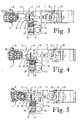
Fig. 3 während des Fahrbetriebs im gekuppelten Zustand, - Fig. 6
- die Kupplungshälfte -aus
Fig. 2 undFig. 3 , perspektivisch dar- gestellt, - Fig. 7
- die Einzelheit VII aus
Fig. 6 , in der Vorderansicht und vergrö- ssert dargestellt, - Fig. 8
- einen Steuerschaltplan für die Kupplung aus
Fig. 3 bis Fig. 5 , schematisch dargestellt, und - Fig. 9
- einen Längsschnitt durch eine Variante einer erfindungsge- mässen Kupplung.
- Fig. 1
- the coupling according to the invention in the coupled state, shown in plan view,
- Fig. 2
- a coupling half of the clutch
Fig. 1 in coupled condition, - Fig. 3
- a longitudinal section through the coupling half
Fig. 2 in an extendable variant, shown in preparation before the coupling process, - Fig. 4
- the coupling half off
Fig. 3 after completion of the coupling process, whereby the coupling is braced, - Fig. 5
- the coupling half off
Fig. 3 while driving in the coupled state, - Fig. 6
- the coupling half -off
Fig. 2 andFig. 3 , in perspective, - Fig. 7
- the detail VII
Fig. 6 , in front view and enlarged, - Fig. 8
- a control circuit diagram for the clutch
FIG. 3 to FIG. 5 , shown schematically, and - Fig. 9
- a longitudinal section through a variant of a erfindungsge- mässen coupling.
Die in
Der Kupplungskopf 4 und die Zugeinrichtung 5 sind konventioneller Bauweise und werden daher nachfolgend nicht näher beschrieben. Die Zugeinrichtung 5 hat bekanntlich die Aufgabe, die im Fahrbetrieb auftretenden Zugkräfte in den Fahrzeugkasten einzuleiten. Hierfür ist sie mit einer Zugstange 10 versehen, die an einem im Fahrzeugkasten angeordneten Bolzen 11 angelenkt ist. An diesem ist auch eine Zuggabel 12 mit einem Federsatz 13 angelenkt.The
In der Kolben/Zylindereinheit ist eine Freihubvorrichtung 6 zugeordnet, wobei der Zylinder 14 stirnseitig am Kupplungskopf 4 befestigt und der Kolben 15 mit der Zugstange 10 der Zugeinrichtung 5 verbunden ist. Durch den Kolben 15 wird im Zylinder 14 eine mit Druckluft beaufschlagbare Kammer 16 definiert, die über die Druckluftspeiseleitung 17 des Fahrzeuges gespeist wird.In the piston / cylinder unit is assigned a free-lifting
Jede Kupplungshälfte 2 bzw. 3 ist am Kopfträger 9 mit einer Höhenabstützung 18 abgestützt. Diese ist durch eine auf elastischen Elementen, wie Gummihohlfedern 19, abgestützte Traverse 20 gebildet, die am Kopfträger 9 mit einer Halterung 21 aufgehängt ist. In der Traverse 20 ist eine Mittenzentrierung 22 integriert, welche den Zylinder 14 der Freihubvorrichtung untergreift und die Kupplungshälfte 2 bzw. 3 in der kupplungsbereiten Position hält oder in diese zurückführt. Der Zylinder 14 ist axial in der Mittenzentrierung 22 verschiebbar. Er kann auch zusammen mit dem Kolben 15 und der Zugstange 10 um einen geringen Winkelbetrag ausgelenkt werden, wobei die Lenkachse mit der Mittelachse des Bolzens 11 zusammenfällt.Each
Die Kupplungshöhe ist mit der Höhenabstützung 18 einstellbar, um sie den Konstruktionsmerkmalen der zu verkuppelnden Fahrzeuge anzupassen.The height of the coupling is adjustable with the
Wie aus
Die Puffervorspannung kann stufenweise durch Einlegen von Distanzscheiben in der Zugeinrichtung 5 eingestellt werden.The buffer bias can be adjusted step by step by inserting spacers in the pulling
Im ungekuppelten bzw. kuppelbereiten Zustand wird der Zylinder 14 mit Druckluft aus der Speiseleitung 17 versorgt und die Kammer 16 beaufschlagt. Dadurch kann der Zylinder 14 den Kupplungskopf 4 voranschieben und die Kupplung im ungekuppelten Zustand in einer definierten Stellung bereithalten: Ausserdem wird damit sichergestellt, dass der Kupplungskopf 4 während des Kuppelvorgangs die nötige Gegendruckkraft entgegensetzt. Dabei wirkt das Luftkissen in der Kammer 16 als Luftfeder, falls beim Kuppelvorgang die Druckkraft durch die Aufprallgeschwindigkeit der Fahrzeuge zu gross ist.In the uncoupled or ready for coupling state, the
Nach abgeschlossenem Kuppelvorgang wird die Kammer 16 entlüftet, so dass die Kupplung während des Fahrbetriebs einen kraftlosen Freihub ausführen kann. Damit wird sichergestellt, dass sie im Betrieb die Fahrzeuge nur mit Zugkräften beansprucht, die den bei herkömmlichen Schraubenkupplungen entsprechen. Dadurch ist es möglich, die erfindungsgemässe Kupplung in vorhandenen Schienenfahrzeugen einzubauen, ohne den Fahrzeugkasten zu verstärken.After completion of the dome operation, the
Der Freihub der Kupplung wird beim Kupplungsvorgang aufgehoben, indem die Kupplung durch Beaufschlagen der Kammer 16 pneumatisch in den vorderen Anschlag des Freihubes gebracht wird.The free lift of the clutch is released during the coupling process by the clutch is pneumatically brought by applying the
Die Variante nach
Durch Beaufschlagung der vorderen Kammer 24 mit Druckluft wird der Kupplungskopf 4 über die Stossfläche der Puffer in Bereitstellung vorgeschoben (
Beim Kuppelvorgang wird die Beaufschlagung der vorderen Kammer 24 aufrechterhalten, was sicherstellt, dass der Kupplungskopf 4 beim Kuppein die nötige Gegendruckkraft aufbringen kann. Sobald der mechanische Kuppelvorgang abgeschlossen ist, wird Hydrauliköl in die hintere Kammer 25 gepresst, wodurch die Kupplung zurückgezogen und mit der erforderlichen Kraft verspannt wird (
Sobald die Zugkraft die Verspannkraft der Kupplung übersteigt, wird die hintere Kammer 25 durch ein Rückschlagventil 27 geschlossen. Das bewirkt, dass die Vorspannlänge der Kupplung gehalten und die Feder 12 der Zugeinrichtung 5 unter dem Einfluss der Zuggabel 12 gespannt wird. In diesem Zustand kann die Kupplung hohe Zugkräfte in der Grössenordnung von bis ca. 1000 kN übertragen. Die Anordnung des Rückschlagventils 27 ist im Schaltplan gemäss
Die erfindungsgemässe Freihubvorrichtung bewirkt, dass die Zugkupplung sich beim Einfedern der Puffer automatisch frei und kraftlos verkürzen kann. Sie kann sich im gekuppelten Zustand in Druckrichtung im Bereich der maximalen Pufferfederwege frei bewegen.The free-lift device according to the invention has the effect that the traction coupling can automatically and freely shorten when the buffers are compressed. It can move freely in the coupled state in the pressure direction in the area of the maximum buffer spring travel.
Die Zugkraft wird in die Fahrzeuge über die Bolzen 11 eingeleitet. Dabei bildet die Kupplung eine gestreckte Linie zwischen den Drehpunkten der Zugstangen 10 in den Mittelachsen dieser Bolzen. Insofern ist das kinematische Verhalten der Kupplung mit dem einer herkömmlichen Schraubenkupplung vergleichbar.The tensile force is introduced into the vehicles via the
Damit der Kupplungsvorgang sicher stattfindet, muss die Zugeinrichtung 5 der Gegenkupplung eine Kraft entgegensetzen, die in der Praxis bis ca. 40 kN betragen kann.In order for the coupling process to take place safely, the towing
Die Erfindung ist mit dem obigen Ausführungsbeispiel ausreichend dargetan. Sie könnte aber noch in anderen Varianten erläutert sein.The invention is sufficiently demonstrated with the above embodiment. But you could still be explained in other variants.
So könnte zum Beispiel bei einer Kupplung 50 gemäss
Claims (15)
zwischen dem Kupplungskopf (4) und dem Fahrzeugkasten eine Spannvorrichtung vorgesehen ist, welche beim Kuppeln eine Längsverstellung zwischen dem Kupplungskopf (4) und dem Fahrzeugkasten und die erforderliche Verspannkraft erzeugt.Automatic coupling for rail vehicles with side buffers (7, 8) for receiving compressive forces, with coupling halves, each having on the one hand a coupling head (4) and on the other hand connected to a pulling device (5) for transmitting the tensile forces to a vehicle body of the rail vehicle, characterized that
between the coupling head (4) and the vehicle body, a tensioning device is provided, which generates a longitudinal adjustment between the coupling head (4) and the vehicle body and the required clamping force when coupling.
der Pneumatikzylinder (14) eine mit Druckluft beaufschlagbare vordere Kammer (24) und eine mit Hydrauliköl beaufschlagbare hintere Kammer (25) aufweist, wobei der Kupplungskopf (4) bei Beaufschlagung der vorderen Kammer (24) in eine Bereitstellung vor die Pufferebene geschoben wird und bei Beaufschlagung der hinteren Kammer (25) zurückgezogen und in der Kuppelstellung verspannt wird, wobei nach erfolgter Kupplung die Entlüftung der vorderen Kammer (24) den kraftlosen Freihub der Kupplung sicherstellt, während die Beaufschlagung der hinteren Kammer (25) die Vorspannlänge der Kupplung aufrechterhält.Coupling according to one of the preceding claims 2 to 6, characterized in that
the pneumatic cylinder (14) has a front chamber (24) which can be acted upon with compressed air and a rear chamber (25) which can be acted upon with hydraulic oil, the coupling head (4) being pushed into a provision in front of the buffer plane when the front chamber (24) is acted upon Exposing the rear chamber (25) is withdrawn and clamped in the coupling position, wherein after the clutch, the venting of the front chamber (24) ensures the power free free travel of the clutch, while the loading of the rear chamber (25) maintains the preload length of the clutch.
der Kupplungsvorgang über ein Mehrwegeventil (28) steuerbar ist.Coupling according to one of claims 1 to 9, characterized in that
the coupling process via a multi-way valve (28) is controllable.
Priority Applications (1)
| Application Number | Priority Date | Filing Date | Title |
|---|---|---|---|
| PL10014549T PL2322403T3 (en) | 2009-11-13 | 2010-11-12 | Automatic coupling for railway vehicles with side buffers |
Applications Claiming Priority (1)
| Application Number | Priority Date | Filing Date | Title |
|---|---|---|---|
| CH01753/09A CH702215A2 (en) | 2009-11-13 | 2009-11-13 | Automatic coupling for rail vehicles with side buffers. |
Publications (3)
| Publication Number | Publication Date |
|---|---|
| EP2322403A2 true EP2322403A2 (en) | 2011-05-18 |
| EP2322403A3 EP2322403A3 (en) | 2012-04-18 |
| EP2322403B1 EP2322403B1 (en) | 2014-09-24 |
Family
ID=43627297
Family Applications (1)
| Application Number | Title | Priority Date | Filing Date |
|---|---|---|---|
| EP10014549.9A Active EP2322403B1 (en) | 2009-11-13 | 2010-11-12 | Automatic coupling for railway vehicles with side buffers |
Country Status (3)
| Country | Link |
|---|---|
| EP (1) | EP2322403B1 (en) |
| CH (1) | CH702215A2 (en) |
| PL (1) | PL2322403T3 (en) |
Cited By (7)
| Publication number | Priority date | Publication date | Assignee | Title |
|---|---|---|---|---|
| EP2537730A1 (en) * | 2011-06-21 | 2012-12-26 | Schwab Verkehrstechnik AG | Buffer or coupling for a rail vehicle |
| EP3205551A1 (en) | 2016-02-12 | 2017-08-16 | Faiveley Transport Schwab AG | Coupling device for a rail vehicle |
| CN108349513A (en) * | 2015-11-05 | 2018-07-31 | 科尔达软件有限公司 | System for coupling and discharging vehicle of the traveling on the railway network automatically |
| CN110525473A (en) * | 2019-09-30 | 2019-12-03 | 中车青岛四方车辆研究所有限公司 | Hitch erecting by overhang |
| EP3608196A1 (en) | 2018-08-08 | 2020-02-12 | Faiveley Transport Schwab AG | Coupling with an electrical coupling for coupling two railway vehicles |
| EP3750771A1 (en) | 2019-06-14 | 2020-12-16 | Faiveley Transport Schwab AG | Coupling with an electric coupling, especially for a rail vehicle |
| EP3855043A1 (en) * | 2020-01-22 | 2021-07-28 | Faiveley Transport Schwab AG | Pulling and pushing device in particular for a coupling of a railway vehicle |
Families Citing this family (2)
| Publication number | Priority date | Publication date | Assignee | Title |
|---|---|---|---|---|
| CH713677B1 (en) | 2017-04-06 | 2021-04-30 | Faiveley Transp Schwab Ag | Linkage device for a coupling of a rail vehicle. |
| CH714078B1 (en) * | 2017-08-23 | 2021-08-16 | Faiveley Transp Schwab Ag | Coupling for a rail vehicle. |
Family Cites Families (6)
| Publication number | Priority date | Publication date | Assignee | Title |
|---|---|---|---|---|
| US2499300A (en) * | 1946-02-23 | 1950-02-28 | Gen Motors Corp | Locomotive coupling device |
| BE571932A (en) * | 1957-10-15 | |||
| NL123487C (en) * | 1959-01-23 | |||
| DE19513386A1 (en) * | 1995-04-08 | 1996-10-10 | Scharfenbergkupplung Gmbh | Adjustable coupling rod |
| DE19757621B4 (en) * | 1997-12-23 | 2005-02-10 | Knorr-Bremse Systeme für Schienenfahrzeuge GmbH | Automatic traction coupling |
| DE10020351A1 (en) * | 2000-04-26 | 2001-11-08 | Knorr Bremse Systeme | Actuating device for an automatic changeover and / or a locking system of an automatic clutch |
-
2009
- 2009-11-13 CH CH01753/09A patent/CH702215A2/en not_active Application Discontinuation
-
2010
- 2010-11-12 EP EP10014549.9A patent/EP2322403B1/en active Active
- 2010-11-12 PL PL10014549T patent/PL2322403T3/en unknown
Non-Patent Citations (1)
| Title |
|---|
| None |
Cited By (9)
| Publication number | Priority date | Publication date | Assignee | Title |
|---|---|---|---|---|
| EP2537730A1 (en) * | 2011-06-21 | 2012-12-26 | Schwab Verkehrstechnik AG | Buffer or coupling for a rail vehicle |
| CN108349513A (en) * | 2015-11-05 | 2018-07-31 | 科尔达软件有限公司 | System for coupling and discharging vehicle of the traveling on the railway network automatically |
| CN108349513B (en) * | 2015-11-05 | 2020-07-03 | 科尔达软件有限公司 | System for automatically coupling and releasing vehicles travelling on the railway network |
| EP3205551A1 (en) | 2016-02-12 | 2017-08-16 | Faiveley Transport Schwab AG | Coupling device for a rail vehicle |
| EP3608196A1 (en) | 2018-08-08 | 2020-02-12 | Faiveley Transport Schwab AG | Coupling with an electrical coupling for coupling two railway vehicles |
| EP3750771A1 (en) | 2019-06-14 | 2020-12-16 | Faiveley Transport Schwab AG | Coupling with an electric coupling, especially for a rail vehicle |
| CN110525473A (en) * | 2019-09-30 | 2019-12-03 | 中车青岛四方车辆研究所有限公司 | Hitch erecting by overhang |
| CN110525473B (en) * | 2019-09-30 | 2024-02-13 | 中车青岛四方车辆研究所有限公司 | Hanging device for coupler |
| EP3855043A1 (en) * | 2020-01-22 | 2021-07-28 | Faiveley Transport Schwab AG | Pulling and pushing device in particular for a coupling of a railway vehicle |
Also Published As
| Publication number | Publication date |
|---|---|
| EP2322403A3 (en) | 2012-04-18 |
| EP2322403B1 (en) | 2014-09-24 |
| CH702215A2 (en) | 2011-05-13 |
| PL2322403T3 (en) | 2015-04-30 |
Similar Documents
| Publication | Publication Date | Title |
|---|---|---|
| EP2322403B1 (en) | Automatic coupling for railway vehicles with side buffers | |
| DE10360516B4 (en) | Device for secondary suspension of a car body in a rail vehicle with an active spring element | |
| DE2625274A1 (en) | COMPRESSED AIR BRAKING SYSTEM FOR COMBINED AUTOMATIC AND DIRECTLY ACTING BRAKING | |
| EP2644775A2 (en) | Self-propelled milling machine, use of a lifting column of a milling machine, and method for increasing the efficiency of a milling machine | |
| DE102006049408B4 (en) | Method and device for replacing a defective or worn rail piece | |
| DE4313473C2 (en) | Closing unit for an injection molding machine | |
| DE3149113A1 (en) | SAFETY DEVICE FOR VEHICLES | |
| DE19944754B4 (en) | Train-pressure buffing gear | |
| DE2805635C2 (en) | Device for lateral veering of motor vehicles | |
| EP3208173A1 (en) | Bogie for a rail vehicle, method for compensating the variation of wheels diameter for rail vehicles and rail vehicle | |
| EP3446944B1 (en) | Coupling for a rail vehicle | |
| EP0915001A1 (en) | Connection between vehicle bodies | |
| DE4311362C2 (en) | Braking system for freight cars | |
| EP3504098B1 (en) | Rail vehicle coupling for connecting two rail vehicles | |
| AT391663B (en) | SEMI-AUTOMATIC EXTENSION ARMS WITH EXTENSION TUBE FOR A TRUCK TRAILER | |
| DE202004014532U1 (en) | Installation box for railway train buffer, has spring held with hinge pins and stop plate screwed with it, which is connected to clutch arm where thrust forces transfer the traction power over moving thrust piece | |
| EP1070645B1 (en) | Supporting device for automatic coupling for rail vehicles | |
| DE2554463A1 (en) | Rail conversion for tractor - with flanged wheels moved by rear and front hitches to sit between pneumatic wheels and rails in friction contact | |
| DE10054762A1 (en) | Run-up brake unit for single-axle vehicle trailers has rod linkage with longitudinal and cross bars and connected to pressure regulators of regulating system connected to wheel brake cylinders of individual trailer wheels | |
| EP1501643B1 (en) | Device and method for mounting a roll ring onto a shaft of a rolling stand | |
| EP3429925A1 (en) | Towing vehicle | |
| DE4236335C2 (en) | Device for locking or fixing a lift for the disabled | |
| EP0306816A1 (en) | Hydraulic length variation device for a coupling bar of a trailer with a central running gear | |
| EP1070646B1 (en) | Automatic coupling for rail vehicles, especially traction coupling | |
| DE102021131726A1 (en) | RAIL CONSTRUCTION HAVING TWO SEPARABLE CONSTRUCTION SECTIONS AND METHODS FOR SEPARATING, FORMING OR MAINTAINING SUCH CONSTITUTION |
Legal Events
| Date | Code | Title | Description |
|---|---|---|---|
| PUAI | Public reference made under article 153(3) epc to a published international application that has entered the european phase |
Free format text: ORIGINAL CODE: 0009012 |
|
| AK | Designated contracting states |
Kind code of ref document: A2 Designated state(s): AL AT BE BG CH CY CZ DE DK EE ES FI FR GB GR HR HU IE IS IT LI LT LU LV MC MK MT NL NO PL PT RO RS SE SI SK SM TR |
|
| AX | Request for extension of the european patent |
Extension state: BA ME |
|
| PUAL | Search report despatched |
Free format text: ORIGINAL CODE: 0009013 |
|
| AK | Designated contracting states |
Kind code of ref document: A3 Designated state(s): AL AT BE BG CH CY CZ DE DK EE ES FI FR GB GR HR HU IE IS IT LI LT LU LV MC MK MT NL NO PL PT RO RS SE SI SK SM TR |
|
| AX | Request for extension of the european patent |
Extension state: BA ME |
|
| RIC1 | Information provided on ipc code assigned before grant |
Ipc: B61G 7/08 20060101AFI20120312BHEP Ipc: B61G 9/24 20060101ALI20120312BHEP |
|
| 17P | Request for examination filed |
Effective date: 20121003 |
|
| 17Q | First examination report despatched |
Effective date: 20130402 |
|
| GRAP | Despatch of communication of intention to grant a patent |
Free format text: ORIGINAL CODE: EPIDOSNIGR1 |
|
| INTG | Intention to grant announced |
Effective date: 20140414 |
|
| GRAS | Grant fee paid |
Free format text: ORIGINAL CODE: EPIDOSNIGR3 |
|
| GRAA | (expected) grant |
Free format text: ORIGINAL CODE: 0009210 |
|
| AK | Designated contracting states |
Kind code of ref document: B1 Designated state(s): AL AT BE BG CH CY CZ DE DK EE ES FI FR GB GR HR HU IE IS IT LI LT LU LV MC MK MT NL NO PL PT RO RS SE SI SK SM TR |
|
| REG | Reference to a national code |
Ref country code: GB Ref legal event code: FG4D Free format text: NOT ENGLISH |
|
| REG | Reference to a national code |
Ref country code: CH Ref legal event code: EP |
|
| REG | Reference to a national code |
Ref country code: AT Ref legal event code: REF Ref document number: 688472 Country of ref document: AT Kind code of ref document: T Effective date: 20141015 |
|
| REG | Reference to a national code |
Ref country code: IE Ref legal event code: FG4D Free format text: LANGUAGE OF EP DOCUMENT: GERMAN |
|
| REG | Reference to a national code |
Ref country code: DE Ref legal event code: R096 Ref document number: 502010007931 Country of ref document: DE Effective date: 20141106 |
|
| REG | Reference to a national code |
Ref country code: CH Ref legal event code: NV Representative=s name: LUCHS AND PARTNER AG PATENTANWAELTE, CH |
|
| REG | Reference to a national code |
Ref country code: SE Ref legal event code: TRGR |
|
| REG | Reference to a national code |
Ref country code: NL Ref legal event code: T3 |
|
| PG25 | Lapsed in a contracting state [announced via postgrant information from national office to epo] |
Ref country code: LT Free format text: LAPSE BECAUSE OF FAILURE TO SUBMIT A TRANSLATION OF THE DESCRIPTION OR TO PAY THE FEE WITHIN THE PRESCRIBED TIME-LIMIT Effective date: 20140924 Ref country code: GR Free format text: LAPSE BECAUSE OF FAILURE TO SUBMIT A TRANSLATION OF THE DESCRIPTION OR TO PAY THE FEE WITHIN THE PRESCRIBED TIME-LIMIT Effective date: 20141225 Ref country code: NO Free format text: LAPSE BECAUSE OF FAILURE TO SUBMIT A TRANSLATION OF THE DESCRIPTION OR TO PAY THE FEE WITHIN THE PRESCRIBED TIME-LIMIT Effective date: 20141224 |
|
| REG | Reference to a national code |
Ref country code: LT Ref legal event code: MG4D |
|
| PG25 | Lapsed in a contracting state [announced via postgrant information from national office to epo] |
Ref country code: CY Free format text: LAPSE BECAUSE OF FAILURE TO SUBMIT A TRANSLATION OF THE DESCRIPTION OR TO PAY THE FEE WITHIN THE PRESCRIBED TIME-LIMIT Effective date: 20140924 Ref country code: RS Free format text: LAPSE BECAUSE OF FAILURE TO SUBMIT A TRANSLATION OF THE DESCRIPTION OR TO PAY THE FEE WITHIN THE PRESCRIBED TIME-LIMIT Effective date: 20140924 Ref country code: LV Free format text: LAPSE BECAUSE OF FAILURE TO SUBMIT A TRANSLATION OF THE DESCRIPTION OR TO PAY THE FEE WITHIN THE PRESCRIBED TIME-LIMIT Effective date: 20140924 Ref country code: HR Free format text: LAPSE BECAUSE OF FAILURE TO SUBMIT A TRANSLATION OF THE DESCRIPTION OR TO PAY THE FEE WITHIN THE PRESCRIBED TIME-LIMIT Effective date: 20140924 |
|
| PG25 | Lapsed in a contracting state [announced via postgrant information from national office to epo] |
Ref country code: ES Free format text: LAPSE BECAUSE OF FAILURE TO SUBMIT A TRANSLATION OF THE DESCRIPTION OR TO PAY THE FEE WITHIN THE PRESCRIBED TIME-LIMIT Effective date: 20140924 Ref country code: PT Free format text: LAPSE BECAUSE OF FAILURE TO SUBMIT A TRANSLATION OF THE DESCRIPTION OR TO PAY THE FEE WITHIN THE PRESCRIBED TIME-LIMIT Effective date: 20150126 Ref country code: SK Free format text: LAPSE BECAUSE OF FAILURE TO SUBMIT A TRANSLATION OF THE DESCRIPTION OR TO PAY THE FEE WITHIN THE PRESCRIBED TIME-LIMIT Effective date: 20140924 Ref country code: RO Free format text: LAPSE BECAUSE OF FAILURE TO SUBMIT A TRANSLATION OF THE DESCRIPTION OR TO PAY THE FEE WITHIN THE PRESCRIBED TIME-LIMIT Effective date: 20140924 Ref country code: IS Free format text: LAPSE BECAUSE OF FAILURE TO SUBMIT A TRANSLATION OF THE DESCRIPTION OR TO PAY THE FEE WITHIN THE PRESCRIBED TIME-LIMIT Effective date: 20150124 Ref country code: EE Free format text: LAPSE BECAUSE OF FAILURE TO SUBMIT A TRANSLATION OF THE DESCRIPTION OR TO PAY THE FEE WITHIN THE PRESCRIBED TIME-LIMIT Effective date: 20140924 Ref country code: CZ Free format text: LAPSE BECAUSE OF FAILURE TO SUBMIT A TRANSLATION OF THE DESCRIPTION OR TO PAY THE FEE WITHIN THE PRESCRIBED TIME-LIMIT Effective date: 20140924 |
|
| REG | Reference to a national code |
Ref country code: PL Ref legal event code: T3 |
|
| REG | Reference to a national code |
Ref country code: DE Ref legal event code: R097 Ref document number: 502010007931 Country of ref document: DE |
|
| PG25 | Lapsed in a contracting state [announced via postgrant information from national office to epo] |
Ref country code: LU Free format text: LAPSE BECAUSE OF FAILURE TO SUBMIT A TRANSLATION OF THE DESCRIPTION OR TO PAY THE FEE WITHIN THE PRESCRIBED TIME-LIMIT Effective date: 20141112 Ref country code: MC Free format text: LAPSE BECAUSE OF FAILURE TO SUBMIT A TRANSLATION OF THE DESCRIPTION OR TO PAY THE FEE WITHIN THE PRESCRIBED TIME-LIMIT Effective date: 20140924 |
|
| PG25 | Lapsed in a contracting state [announced via postgrant information from national office to epo] |
Ref country code: DK Free format text: LAPSE BECAUSE OF FAILURE TO SUBMIT A TRANSLATION OF THE DESCRIPTION OR TO PAY THE FEE WITHIN THE PRESCRIBED TIME-LIMIT Effective date: 20140924 |
|
| PLBE | No opposition filed within time limit |
Free format text: ORIGINAL CODE: 0009261 |
|
| STAA | Information on the status of an ep patent application or granted ep patent |
Free format text: STATUS: NO OPPOSITION FILED WITHIN TIME LIMIT |
|
| GBPC | Gb: european patent ceased through non-payment of renewal fee |
Effective date: 20141224 |
|
| REG | Reference to a national code |
Ref country code: IE Ref legal event code: MM4A |
|
| 26N | No opposition filed |
Effective date: 20150625 |
|
| PG25 | Lapsed in a contracting state [announced via postgrant information from national office to epo] |
Ref country code: GB Free format text: LAPSE BECAUSE OF NON-PAYMENT OF DUE FEES Effective date: 20141224 Ref country code: IE Free format text: LAPSE BECAUSE OF NON-PAYMENT OF DUE FEES Effective date: 20141112 |
|
| REG | Reference to a national code |
Ref country code: FR Ref legal event code: PLFP Year of fee payment: 6 |
|
| PG25 | Lapsed in a contracting state [announced via postgrant information from national office to epo] |
Ref country code: SI Free format text: LAPSE BECAUSE OF FAILURE TO SUBMIT A TRANSLATION OF THE DESCRIPTION OR TO PAY THE FEE WITHIN THE PRESCRIBED TIME-LIMIT Effective date: 20140924 |
|
| PG25 | Lapsed in a contracting state [announced via postgrant information from national office to epo] |
Ref country code: SM Free format text: LAPSE BECAUSE OF FAILURE TO SUBMIT A TRANSLATION OF THE DESCRIPTION OR TO PAY THE FEE WITHIN THE PRESCRIBED TIME-LIMIT Effective date: 20140924 |
|
| PG25 | Lapsed in a contracting state [announced via postgrant information from national office to epo] |
Ref country code: BG Free format text: LAPSE BECAUSE OF FAILURE TO SUBMIT A TRANSLATION OF THE DESCRIPTION OR TO PAY THE FEE WITHIN THE PRESCRIBED TIME-LIMIT Effective date: 20140924 |
|
| PG25 | Lapsed in a contracting state [announced via postgrant information from national office to epo] |
Ref country code: MT Free format text: LAPSE BECAUSE OF FAILURE TO SUBMIT A TRANSLATION OF THE DESCRIPTION OR TO PAY THE FEE WITHIN THE PRESCRIBED TIME-LIMIT Effective date: 20140924 Ref country code: TR Free format text: LAPSE BECAUSE OF FAILURE TO SUBMIT A TRANSLATION OF THE DESCRIPTION OR TO PAY THE FEE WITHIN THE PRESCRIBED TIME-LIMIT Effective date: 20140924 Ref country code: HU Free format text: LAPSE BECAUSE OF FAILURE TO SUBMIT A TRANSLATION OF THE DESCRIPTION OR TO PAY THE FEE WITHIN THE PRESCRIBED TIME-LIMIT; INVALID AB INITIO Effective date: 20101112 |
|
| REG | Reference to a national code |
Ref country code: FR Ref legal event code: PLFP Year of fee payment: 7 |
|
| PGFP | Annual fee paid to national office [announced via postgrant information from national office to epo] |
Ref country code: CH Payment date: 20161130 Year of fee payment: 7 |
|
| REG | Reference to a national code |
Ref country code: FR Ref legal event code: PLFP Year of fee payment: 8 |
|
| PG25 | Lapsed in a contracting state [announced via postgrant information from national office to epo] |
Ref country code: MK Free format text: LAPSE BECAUSE OF FAILURE TO SUBMIT A TRANSLATION OF THE DESCRIPTION OR TO PAY THE FEE WITHIN THE PRESCRIBED TIME-LIMIT Effective date: 20140924 |
|
| PG25 | Lapsed in a contracting state [announced via postgrant information from national office to epo] |
Ref country code: LI Free format text: LAPSE BECAUSE OF NON-PAYMENT OF DUE FEES Effective date: 20171130 Ref country code: CH Free format text: LAPSE BECAUSE OF NON-PAYMENT OF DUE FEES Effective date: 20171130 |
|
| REG | Reference to a national code |
Ref country code: FR Ref legal event code: PLFP Year of fee payment: 9 |
|
| PG25 | Lapsed in a contracting state [announced via postgrant information from national office to epo] |
Ref country code: AL Free format text: LAPSE BECAUSE OF FAILURE TO SUBMIT A TRANSLATION OF THE DESCRIPTION OR TO PAY THE FEE WITHIN THE PRESCRIBED TIME-LIMIT Effective date: 20140924 |
|
| PGFP | Annual fee paid to national office [announced via postgrant information from national office to epo] |
Ref country code: SE Payment date: 20221118 Year of fee payment: 13 Ref country code: NL Payment date: 20221118 Year of fee payment: 13 Ref country code: IT Payment date: 20221122 Year of fee payment: 13 Ref country code: FR Payment date: 20221122 Year of fee payment: 13 Ref country code: FI Payment date: 20221121 Year of fee payment: 13 Ref country code: DE Payment date: 20221104 Year of fee payment: 13 Ref country code: AT Payment date: 20221121 Year of fee payment: 13 |
|
| PGFP | Annual fee paid to national office [announced via postgrant information from national office to epo] |
Ref country code: PL Payment date: 20221024 Year of fee payment: 13 Ref country code: BE Payment date: 20221118 Year of fee payment: 13 |
|
| P01 | Opt-out of the competence of the unified patent court (upc) registered |
Effective date: 20230530 |