EP2320136B1 - Installation frame with fixing device - Google Patents
Installation frame with fixing device Download PDFInfo
- Publication number
- EP2320136B1 EP2320136B1 EP10189712.2A EP10189712A EP2320136B1 EP 2320136 B1 EP2320136 B1 EP 2320136B1 EP 10189712 A EP10189712 A EP 10189712A EP 2320136 B1 EP2320136 B1 EP 2320136B1
- Authority
- EP
- European Patent Office
- Prior art keywords
- installation frame
- clamping element
- state
- mounting frame
- clamping
- Prior art date
- Legal status (The legal status is an assumption and is not a legal conclusion. Google has not performed a legal analysis and makes no representation as to the accuracy of the status listed.)
- Not-in-force
Links
Images


Classifications
-
- F—MECHANICAL ENGINEERING; LIGHTING; HEATING; WEAPONS; BLASTING
- F21—LIGHTING
- F21V—FUNCTIONAL FEATURES OR DETAILS OF LIGHTING DEVICES OR SYSTEMS THEREOF; STRUCTURAL COMBINATIONS OF LIGHTING DEVICES WITH OTHER ARTICLES, NOT OTHERWISE PROVIDED FOR
- F21V21/00—Supporting, suspending, or attaching arrangements for lighting devices; Hand grips
- F21V21/02—Wall, ceiling, or floor bases; Fixing pendants or arms to the bases
- F21V21/04—Recessed bases
Definitions
- the invention relates to a mounting frame, in particular for recessed lighting, with a fastening device.
- the fastening device allows the installation of the mounting frame in a section of a false ceiling.
- the false ceiling can be a suspended ceiling or any plate, such as an intermediate plate in a piece of furniture, a partition or an intermediate floor.
- Recessed luminaires for mounting in such intermediate ceilings are known from the prior art.
- EP 0 870 982 A2 and DE 33 29 794 A1 each recessed lights described which are held by means of a screw thread in position.
- components of the mounting frame are moved against each other until the false ceiling is clamped.
- a spring component engages in the screw thread, thereby preventing it from slipping out.
- the components must be moved against each other by hand or with the aid of a screwing tool, which is cumbersome especially in an overhead installation in a false ceiling.
- the described fuse complicates the disassembly of the mounting frame.
- the DE 10 2007 036 979 A1 describes a fastener for a recessed light.
- the fastener includes a locking member that can be moved relative to a base member between a mounting position and a locking position.
- the locking element can be pivoted so far outwardly by a vertical axis that it engages over a ceiling part. In the swung-in state On the other hand, the locking element runs tangentially to the circumferential line of the installation frame.
- a recessed luminaire which includes a pair of rotary bolts for mounting the lamp.
- the rotary latch are pivoted to its locking position to the outside and pulled against the undercut surface.
- a Formrichtgesperre allows axial movement only in the feed direction.
- the object is achieved by a mounting frame according to claim 1.
- the force required for clamping the false ceiling generated by a first spring element, and a part of the fastening device in the cross section of the mounting frame is displaced to facilitate insertion into the false ceiling.
- the mounting frame according to the invention in this case has a support element, which rests in the installed state of the mounting frame on a first surface of the false ceiling, and a pressing member which rests on a second surface of the false ceiling, wherein the first and second surfaces face each other.
- the pressure element is mounted in a direction to the support member and movable away from it.
- the mounting frame according to the invention has a first spring element, which exerts an axial force on the contact pressure element in the direction of the support element. In the assembled state, the intermediate ceiling between the contact pressure element and the support element is clamped in this way.
- the pressing element according to the invention in a plane parallel to the mounting plane of the mounting frame displaced to form a first, retracted state in which contact pressure for insertion of the mounting frame in the cut is at least partially retracted within the clear width of the cutout, and a second, extended state to form, in which the pressing element is extended over the edge of the clear width of the cutout and the support element is substantially opposite to clamp the false ceiling. Due to the displaceability of the pressing element so that the insertion of the mounting frame is facilitated in the cutout of the false ceiling. Furthermore, the pressing element in the second, extended state prevents slipping out of the mounting frame from the false ceiling.
- the pressing element is pivotally mounted. This makes it possible to put the mounting frame in a first, retracted state in which the cross section of the mounting frame is minimized at the level of one or more pressing elements, and a simple insertion of the mounting frame is made possible in the cutout of a false ceiling. Furthermore, a swinging of the pressing element is thereby possible, whereby the pressing element comes to rest on a back of the false ceiling. Swinging is a particularly simple method the cross-sectional enlargement, which can be easily performed by a fitter even with limited visibility.
- the pressing element is displaceable in a different manner, for example, it may be displaceable along an axis.
- the mounting frame also has a resting surface against which presses the pressing member in the first, retracted state, wherein the axial distance between the rest surface and the support element is greater than the thickness of the false ceiling.
- a bias of the first spring element results.
- this is then guided by the bias on the surface of the false ceiling, without the fitter would have to spend a force for this purpose.
- it is therefore only necessary to shift the contact element horizontally outwards.
- the mounting frame moreover has a holding surface which prevents the pressing element from moving back from the second, extended state into the first, retracted state.
- the holding surface extends substantially perpendicular to the mounting plane. In this way, unintentional disassembly of the mounting frame is avoided.
- the mounting frame has a biasing element, which presses the pressing element in the first, retracted state.
- the biasing member may be formed, for example, as a coil spring or leaf spring. Since the first, retracted state corresponds to the state during assembly, an accidental transition to the second, extended state during assembly is prevented. Furthermore, this ensures that a fixing of the mounting frame only happens when the fitter actively displaces the contact pressure.
- the contact pressure element is guided by means of a guide device in the axial direction. This ensures that the contact element moves only in the axial direction, and accidental avoidance in another direction is avoided. Especially when mounting a heavier recessed light it can make sense to use a first spring element with a high spring constant. The converted by such a spring during assembly forces are directed in this embodiment by the guide device, so that damage to the mounting frame and / or the false ceiling and injury to the fitter is avoided when improper installation.
- the guide device is rod-shaped and the contact pressure element has a guide region, wherein the guide region engages around the rod-shaped guide device.
- the guide region can have, for example, one or more through holes or one or more clip elements. This offers the advantage that the contact pressure element can only be moved along the rod. Furthermore, this allows a secure guidance of the contact pressure element.
- the guide by gripping the rod-shaped guide device also reduces a risk of injury to the fitter.
- the first spring element is designed as a spiral spring, which is arranged along the guide device.
- the spiral spring can be arranged around the guide rod. This results in a space-saving arrangement of guide means, first spring element and contact pressure.
- At least two pressing elements are present, which are formed in pairs as wing elements. This offers the advantage that with the help of a single handle two pressing elements can be extended simultaneously by the installer. Furthermore, a paired arrangement allows a horizontal bias of two contact elements by means of a single, biasing member.
- the support element is designed as a circumferential or at least partially circumferential flange. This results on the one hand, the advantage that a possibly existing horizontal gap between the mounting frame and false ceiling is covered by the support element. On the other hand, this results in the possibility to provide several pressing elements whose forces act against the same support element.
- the support element or the flange is round, in particular circular.
- the flange may be angular, in particular rectangular, eg square. It is also advantageous if the outer contour of the flange is adapted to the shape of the mounting frame. This is the case, for example, with a circular flange which is coupled to a cylindrical mounting ring.
- the mounting frame further comprises a blocking element at a fixed distance from the support element.
- the blocking element On a part of its surface, the blocking element has a surface structure into which a portion of the surface of the contact pressure element can couple.
- a frictional connection between the contact pressure element and the blocking element is generated, which counteracts an axial movement of the pressing element.
- Such a coupled state prevents in particular a removal of the contact pressure element from the false ceiling in the installed state. This offers the advantage that a part of the force acting in the installed state, which is required for clamping the false ceiling, can be delivered via the blocking element to the mounting frame.
- the blocking element may be integral with other components of the mounting frame, e.g. be formed on a mounting ring.
- the blocking element in this case has a notch
- the pressing member has a projection which can engage in the notch.
- the formation of the surface structure as a notch or projection allows easy production of the components.
- the projection may be sized to allow easy coupling into the notch.
- the notch or the projection may extend in particular in a direction parallel to the installation plane. In this way, there is a larger contact surface between notch and projection, whereby the force acting in the clamped state is better distributed.
- the notches or projections are each spaced apart in the axial direction, ie perpendicular to the installation plane.
- this preferred embodiment allows a mounting of the mounting frame in false ceilings of different thicknesses. At different thicknesses of the false ceiling, the pressing element has different distances to the support element in the installed state of the mounting frame. The arrangement of a plurality of notches or projections in the axial direction therefore allows securing of the pressing element for different thicknesses of the false ceiling.
- the pressing element is also tiltable about an axis which is perpendicular to the axial direction.
- the pressing element can assume a first, untilted and a second, tilted state.
- the surface structures of the pressing element or of the blocking element engage only in the second, tilted state. In this state results in a contact surface over which the frictional connection is generated, which counteracts an axial movement of the pressing member.
- the surface structures are not coupled, so that unimpeded movement of the contact element in the axial direction is possible. Therefore, the first, untilted state has the advantage that the pressure element can easily be guided during assembly against the surface of the false ceiling and can be removed from there.
- the pressing element is transferred to the second, tilted state in this embodiment.
- the coupled surface structures act as an additional securing mechanism adjacent to the first spring element.
- the tiltability of the contact element allows an easy transfer from the first to the second state, which facilitates the assembly, in particular with limited visibility and overhead mounting.
- the pressing element is transferred in the installed state of the mounting frame by a bearing force in the second, tilted state.
- the contact force is created by the pressing of the pressing element on the O-bei specifications the false ceiling by the first spring element, whereby a torque is generated, which causes a tilting of the pressing element.
- the second, tilted state generated thereby the surface structures of the pressing element and of the blocking element engage in one another, whereby an axial movement of the pressing element and thus disassembly of the mounting frame is prevented.
- the pressing element also has an operating section, via which a fitter can exert a force on the contact pressure element.
- the force generates a torque which transfers the contact pressure element into the first, untilted state.
- the surface structures of the pressing element and the blocking element are not coupled. This allows an axial movement of the pressing element and thus a facilitated disassembly of the mounting frame.
- the operating section allows a simple, tool-free disassembly, which is easily possible even with limited visibility and an overhead work of the mechanic.
- the operating section may be formed, for example, as an edge or surface on the contact pressure element. Alternatively, it can also be attached to the pressing element as an additional, outwardly pointing handle.
- the mounting frame on several pressing elements.
- an arrangement of several pressing elements at different positions of the mounting frame allows a more even distribution of forces. This results in a more advantageous distribution of force both in the mounting frame and in the false ceiling, which counteracts premature material fatigue.
- two pressing elements are arranged in pairs.
- the contact elements can be identical.
- Particularly preferred is the paired arrangement of two identical pressing elements, which are rotated by 180 ° to each other. This results in an advantage in that only one type of pressing must be made. This reduces the production costs.
- the installation frame according to the invention of the fastening device is shown using the example of a mounting frame for a circular downlight.
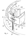
- FIG. 1 shows the mounting frame 1 in a preferred embodiment, which is inserted into the false ceiling 100.
- the mounting frame 1 comprises a cylindrical side wall 40.
- On the outer side of the side wall 40 a plurality of pressing elements 30 are arranged, which are formed in this embodiment as wing elements.
- the support element 20 terminates as a circumferential flange on the underside.
- the side wall 40 and the support element 20 are rigidly connected together.
- the pressing elements 30 rest on the false ceiling 100. They lie opposite the flange-like support element 20, and clamp together with this the false ceiling 100 a.
- the mounting frame 1 has a rod-shaped guide device 41. Along the guide means 41, the pressing elements can be moved to the false ceiling 100 to or from this.
- the side wall 40 is extended in a direction away from the false ceiling 100.
- the extended portion 401 in this case has a vertical gap 402, in which the rod-shaped guide means 41 is arranged.
- the guide device 41 is attached at one end to the side wall 40.
- a head element 42 At the other end it is held in position by a head element 42.
- the head element 42 is attached to the extended portion 401 of the side wall.
- the thus fixed guide means 41 allows a guided movement of the pressing member 30 in the axial direction. Also in FIG. 1 it can be seen that the pressing elements 30 abut in the mounted state on the outer surface of the side wall 40. In this way, a moving back of the pressing elements 30 is prevented in the interior of the mounting frame 1.
- FIG. 2 shows the same installation frame FIG. 1 in a supervision.
- four wing-shaped pressing elements 30 can be seen, which are arranged in pairs.
- two wing-shaped pressing elements 30 are mounted on a guide device 41.
- FIG. 2 is clearly seen how the cross-sectional area of the mounting frame 1 is increased by the pressing elements 30 are extended from the interior of the mounting frame 1.
- the contact pressure elements 30 are in the region of their diegelend Schemee 303 on the outer surface of the side wall 40 at.
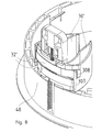
- FIG. 3 shows the mounting frame 1 in the unmounted state.
- the pressing elements 30 rest on an upper resting surface 403 of the side wall 40 and are pivoted into the interior of the mounting frame 1.
- the cross-sectional area of the mounting frame 1 is minimized, so that a performing of the mounting frame 1 by a Section of the false ceiling 100 is facilitated for assembly.
- the contact pressure elements 30 in the unassembled state of the installation frame have a greater axial distance to the support element 20 than in the mounted state. For an attachment of the mounting frame 1 to the false ceiling 100, it is therefore necessary to shift the pressing elements to the outside and at the same time to move them downwards, in the direction of the support element 20.
- the first spring element 31 is formed in the illustrated embodiment as a spiral spring, which is plugged onto the rod-shaped guide means 41 and is located between the paired pressing members 30 and the head member 42.
- the pressing elements 30 in this case have guide regions 301, which encompass the guide device 41. In this way, a guidance of the pressing elements 30 in the axial direction along the guide device is made possible.
- this storage also allows pivoting of the pressing elements 30 in a horizontal plane around the guide device 41 around. In the in FIG. 4 illustrated first, retracted state, the pressing elements 30 are on a resting surface 403 of the side wall 40. As a result, an axial movement of the pressing elements 30 in the direction of the support element 20 is prevented.
- the fitter exerts a force on the copegelend Schemee 303 of the pressing members 30 to push them outward on the side wall 40 to. This causes a torque which leads to a rotation of the pressing members 30 around the guide means 41 around. In this way, the fitter swivels the pressing elements 30 outwards. As a result, the pressing elements 30 are transferred to a second, pivoted-out state, in which they no longer rest on the resting surface 403.
- the coil spring 31 generates an axial force which presses the pressing elements 30 downwards in the direction of the support element 20. The movement ends when the pressing elements 30 rest on the surface of the false ceiling 100, which is thereby clamped between the pressing elements 30 and the support element 20.
- a biasing element in the form of a second spring element 32 can be seen, which is formed in this embodiment as a spiral spring.
- the second spring element 32 is also mounted on the guide means 41 and is located between two guide portions 301 of the two paired pressing members 30.
- the ends of the coil spring 32 engage in the guide portions 301 of the wing members 30 such that the coil spring 32, the wing elements 30th pushed inward, in the first, swung state. This prevents inadvertent pivoting of the wing elements 30 to the outside.
- the second spring element 32 presses the pressing elements 30 with their viagelend Schemeen 303 against the outer wall 40. In this way, the horizontal position of the pressing is fixed and an unintentional intermediate pivoting avoided.
- FIG. 6 shows a detailed view of the pressing member 30.
- the pressing member 30 is formed in the preferred embodiment as a wing member comprising a wing outer portion 303 and guide portions 301 has.
- each pressing element has two guide regions 301 which are approximately at right angles to the wing outer region 303.
- the guide portions 301 each have a through hole 305.
- the through holes 305 surround the guide 41, which is fixed to the side wall 40.
- the through-holes 305 have a smooth inner surface in the preferred embodiment.
- Both the through holes 305 and the guide 41 have a circular cross section.
- the diameter of the through-holes 305 is slightly larger than the diameter of the rod-shaped guide device 41.
- This type of mounting of the contact-pressure element 30 enables three types of movement: a) axial displacement of the contact-pressure element 30 on the guide device 41, b) pivoting of the contact-pressure element 30 around the guide means 41 in a horizontal plane, and c) tilting the pressing member 30 about an axis which is perpendicular to the guide means 41.
- the latter tilting movement is made possible in that the through holes 305 have a larger diameter than the guide means 41. The effect of the tilting movement will be described in detail in the next section.
- the pressing member 30 further has projections 302 on a surface of one of its guide portions 301.
- the projections are oriented toward the interior of the mounting frame. This corresponds to the Condition in which the mounting frame is mounted.
- the protrusions 302 face to the side, toward the side wall 40.
- the side wall 40 in this area a plurality of parallel notches 406 on.
- the notches 406 are arranged along the gap 402 and surround the guide device 41.
- the guide regions 301 of the pressing elements 30 do not engage around the rod-shaped guide device 41 in a form-fitting manner, but leave play.
- the gap 402, the guide regions 301, the projections 302 and the guide device 41 are dimensioned such that the projections 302 do not couple into the notches 406 when the pressing elements are in a first, untilted state. Only by tilting the pressing elements 30, the projections 302 engage in the notches 406, so that a bearing surface is formed, via which a force acts on the pressing member 30, which counteracts an axial movement of the pressing member 30.
- the pressing member 30 is in the second, tilted state, the axial position of the pressing member 30 with respect to the support member 20 is thus fixed.
- the pressing elements 30 have foot sections 304 in the lower region, as can be seen in FIG.
- a bearing force acts on these foot sections 304.
- a torque is generated, which causes a tilting of the pressing elements 30 about an axis perpendicular to the guide device 41.
- the pressing elements are transferred to the second, tilted state.
- the projections 302 engage with the notches 406, whereby a locking mechanism is generated, which prevents unintentional release of the pressing elements 30 in the mounted state of the mounting frame 1.
- the pressing elements 30 have operating sections 306, as in FIG FIG. 6 is recognizable.
- the operating portions 306 are formed in the illustrated embodiment as projecting elements on the guide portions 301, and point in the second, extended state of the mounting frame in the direction of its interior. In this way, they are accessible to the fitter, so that this can spend a disassembly on the operating section 306 a force on the pressing member 30 upwards. Since the operating sections 306 are located significantly closer to the guide device 41 than the foot sections 304, this exertion of force generates a torque which counteracts the tilting of the pressing elements 30.
- Figure 7a shows the same preferred embodiment of the mounting frame 1 in an exploded view.
- the smooth outer surface of the side wall 40 is not shown, so that support ribs 45 are visible.
- the head element 42 is attached to an extended portion 401 of the side wall 40.
- the guide device 41 is mounted delimitingly by the head element 42 and the side wall 40. This is inserted at its upper end in the head element 42 and at its lower end in a hole 404 which is located in an intermediate rib of the side wall 40.
- the guide device 41 is fixed in an axial direction, perpendicular to the plane defined by the support element 20 level.
- the guide means 41 is also not rotatably mounted.
- the guide device 41 serves to arrange the first spring element 31, a pair of wing elements 30 and the second spring element 32.
- the spring element 31 designed as a spiral spring engages against the head element 42 at the upper end.
- the first spring element 31 engages against the arrangement consisting of two pressing elements 30 and second spring element 32, as shown in FIG FIG. 4 can be seen more clearly.
- the pressing elements 30 each have two guide regions 301. These are nested in the arrangement on the guide device 41 such that the upper guide region of the second contact pressure element follows the upper guide region of the first contact pressure element. Then follows the second spring element 32, which is followed by the lower guide region of the first pressing element, followed by the lower guide region of the second pressing element.
- the second spring element 32 separates in this way the two upper guide areas of the two lower guide areas. Furthermore, engages by this structure, the second spring element 32 at its one end against the first pressing member, and at its second end against the second pressing member.
- the spring force generated therefore acts on both wing elements and is effective to pivot both pressing elements in the direction of the interior of the mounting frame 1.
- the fitter presses the pressing elements 30 outward at their wing end regions 303, so that the second spring element 32 is additionally tensioned.
- the wing elements 30 slide downwards, in the direction of the support element 20.
- the wing elements 30 abut against an outer surface of the side wall 40 in the region of their wing outer regions 303.
- the spring force of The second spring element 32 presses horizontally the wing outer regions 303 against the side wall 40. This causes a horizontal fixation of the wing elements 30th
- the installer attacks from the interior of the mounting frame 1 to the wing elements 30.
- the wing members 30 Once the wing members 30 are above the side wall 40, the wing members 30, driven by the force of the second spring member 32, pivot inwardly. In this position, the wing elements are held by the second spring element 32.
- the force caused by the first spring element 31 now acts against the resting surface 403 of the side wall 40.
- FIG. 8 shows a further embodiment in which the biasing element is formed by two leaf springs 32 '.
- the leaf springs engage in a fastening device 307, which is provided in the contact pressure element 30 ', and on a guide device 308 on the opposing pressure element 30'.
- each leaf spring 32 ' engages at one end thereof into one and at its other end into the other end of the paired pressing members. In this way, a bias voltage is achieved, which presses the pressing elements 30 'with their wing outer region 303 in the direction of the interior of the mounting frame 1.
Description
Die Erfindung betrifft einen Einbaurahmen, insbesondere für Einbauleuchten, mit einer Befestigungsvorrichtung. Die Befestigungsvorrichtung erlaubt die Montage des Einbaurahmens in einem Ausschnitt einer Zwischendecke. Die Zwischendecke kann dabei eine abgehängte Raumdecke oder eine beliebige Platte, beispielsweise eine Zwischenplatte in einem Möbelstück, eine Zwischenwand oder ein Zwischenboden sein.The invention relates to a mounting frame, in particular for recessed lighting, with a fastening device. The fastening device allows the installation of the mounting frame in a section of a false ceiling. The false ceiling can be a suspended ceiling or any plate, such as an intermediate plate in a piece of furniture, a partition or an intermediate floor.
Einbauleuchten zur Montage in derartigen Zwischendecken sind aus dem Stand der Technik bekannt. So sind beispielsweise in
Ferner ist aus der
Die
Darüber hinaus ist aus der
Weiterhin sind in
In
Es ist daher Aufgabe der Erfindung, einen Einbaurahmen mit Befestigungsvorrichtung zur Verfügung zu stellen, welcher eine einfache Montage und Demontage ermöglicht.It is therefore an object of the invention to provide a mounting frame with fastening device available, which allows easy assembly and disassembly.
Die Aufgabe wird erfindungsgemäß durch einen Einbaurahmen nach Anspruch 1 gelöst. Die zum Einspannen der Zwischendecke benötigte Kraft durch ein erstes Federelement erzeugt, und ein Teil der Befestigungsvorrichtung in den Querschnitt des Einbaurahmens verlagerbar ist, um ein Einführen in die Zwischendecke zu erleichtern.The object is achieved by a mounting frame according to
Der erfindungsgemäße Einbaurahmen weist dabei ein Auflageelement auf, welches im eingebauten Zustand des Einbaurahmens auf einer ersten Oberfläche der Zwischendecke anliegt, sowie ein Anpresselement, welches auf einer zweiten Oberfläche der Zwischendecke anliegt, wobei die erste und zweite Oberfläche einander gegenüberliegen. Das Anpresselement ist dabei in einer Richtung auf das Auflageelement zu und von diesem weg beweglich gelagert. Ferner weist der erfindungsgemäße Einbaurahmen ein erstes Federelement auf, welches eine axiale Kraft auf das Anpresselement in Richtung des Auflageelements ausübt. Im montierten Zustand wird auf diese Weise die Zwischendecke zwischen dem Anpresselement und dem Auflageelement eingespannt. Darüber hinaus ist das Anpresselement erfindungsgemäß in einer Ebene parallel zur Einbauebene des Einbaurahmens verlagerbar, um einen ersten, eingefahrenen Zustand zu bilden, in welchem Anpresselement für ein Einführen des Einbaurahmens in den Ausschnitt zumindest teilweise innerhalb der lichten Weite des Ausschnitts eingefahren ist, und um einen zweiten, ausgefahrenen Zustand zu bilden, in welchem das Anpresselement über den Rand der lichten Weite des Ausschnitts ausgefahren ist und dem Auflageelement im Wesentlichen gegenüberliegt, um die Zwischendecke einzuspannen. Durch die Verlagerbarkeit des Anpresselements ist damit das Einführen des Einbaurahmens in den Ausschnitt der Zwischendecke erleichtert. Ferner verhindert das Anpresselement im zweiten, ausgefahrenen Zustand ein Herausrutschen des Einbaurahmens aus der Zwischendecke.The mounting frame according to the invention in this case has a support element, which rests in the installed state of the mounting frame on a first surface of the false ceiling, and a pressing member which rests on a second surface of the false ceiling, wherein the first and second surfaces face each other. The pressure element is mounted in a direction to the support member and movable away from it. Furthermore, the mounting frame according to the invention has a first spring element, which exerts an axial force on the contact pressure element in the direction of the support element. In the assembled state, the intermediate ceiling between the contact pressure element and the support element is clamped in this way. In addition, the pressing element according to the invention in a plane parallel to the mounting plane of the mounting frame displaced to form a first, retracted state in which contact pressure for insertion of the mounting frame in the cut is at least partially retracted within the clear width of the cutout, and a second, extended state to form, in which the pressing element is extended over the edge of the clear width of the cutout and the support element is substantially opposite to clamp the false ceiling. Due to the displaceability of the pressing element so that the insertion of the mounting frame is facilitated in the cutout of the false ceiling. Furthermore, the pressing element in the second, extended state prevents slipping out of the mounting frame from the false ceiling.
In einer bevorzugten Ausführungsform ist das Anpresselement schwenkbar gelagert. Hierdurch wird es ermöglicht, den Einbaurahmen in einen ersten, eingefahrenen Zustand zu versetzen, in welchem der Querschnitt des Einbaurahmens auf der Höhe des einen oder der mehreren Anpresselemente minimiert ist, und ein einfaches Einführen des Einbaurahmens in den Ausschnitt einer Zwischendecke ermöglicht wird. Ferner ist hierdurch ein Ausschwenken des Anpresselementes möglich, wodurch das Anpresselement auf einer Rückseite der Zwischendecke zum Anliegen kommt. Das Ausschwenken stellt dabei eine besonders einfache Methode der Querschnittsvergrößerung dar, welche von einem Monteur auch bei eingeschränkter Sicht leicht durchgeführt werden kann. In weiteren Ausführungsformen ist das Anpresselement auf eine andere Weise verlagerbar, beispielsweise kann es entlang einer Achse verschiebbar sein.In a preferred embodiment, the pressing element is pivotally mounted. This makes it possible to put the mounting frame in a first, retracted state in which the cross section of the mounting frame is minimized at the level of one or more pressing elements, and a simple insertion of the mounting frame is made possible in the cutout of a false ceiling. Furthermore, a swinging of the pressing element is thereby possible, whereby the pressing element comes to rest on a back of the false ceiling. Swinging is a particularly simple method the cross-sectional enlargement, which can be easily performed by a fitter even with limited visibility. In further embodiments, the pressing element is displaceable in a different manner, for example, it may be displaceable along an axis.
In einer besonders vorteilhaften Ausführungsform weist der Einbaurahmen außerdem eine Ruhefläche auf, gegen welche das Anpresselement in dem ersten, eingefahrenen Zustand drückt, wobei der axiale Abstand zwischen der Ruhefläche und dem Auflageelement größer ist als die Dicke der Zwischendecke. Auf diese Weise ergibt sich eine Vorspannung des ersten Federelements. Bei einem Ausfahren des Anpresselementes wird dieses dann durch die Vorspannung auf die Oberfläche der Zwischendecke geführt, ohne dass der Monteur hierzu eine Kraft aufwenden müsste. Zur Montage ist es daher nur erforderlich, das Anpresselement horizontal nach außen zu verlagern. Ein besonderer Vorteil ergibt sich dadurch, dass die zum Einspannen der Zwischendecke erforderliche Kraft nicht von dem Monteur selbst aufgewendet werden muss.In a particularly advantageous embodiment, the mounting frame also has a resting surface against which presses the pressing member in the first, retracted state, wherein the axial distance between the rest surface and the support element is greater than the thickness of the false ceiling. In this way, a bias of the first spring element results. Upon extension of the pressing element this is then guided by the bias on the surface of the false ceiling, without the fitter would have to spend a force for this purpose. For mounting, it is therefore only necessary to shift the contact element horizontally outwards. A particular advantage results from the fact that the force required to clamp the false ceiling does not have to be used by the installer himself.
In einer bevorzugten Ausführungsform weist der Einbaurahmen darüber hinaus eine Haltefläche auf, welche ein Zurückbewegen des Anpresselementes aus dem zweiten, ausgefahrenen Zustand in den ersten, eingefahrenen Zustand verhindert. Die Haltefläche verläuft dabei im Wesentlichen senkrecht zur Einbauebene. Auf diese Weise wird eine unbeabsichtigte Demontage des Einbaurahmens vermieden.In a preferred embodiment, the mounting frame moreover has a holding surface which prevents the pressing element from moving back from the second, extended state into the first, retracted state. The holding surface extends substantially perpendicular to the mounting plane. In this way, unintentional disassembly of the mounting frame is avoided.
In einer bevorzugten Ausführungsform weist der Einbaurahmen ein Vorspannelement auf, welches das Anpresselement in den ersten, eingefahrenen Zustand drückt. Das Vorspannelement kann beispielsweise als Spiralfeder oder Blattfeder ausgebildet sein. Da der erste, eingefahrene Zustand dem Zustand während der Montage entspricht, wird ein versehentlicher Übergang in den zweiten, ausgefahrenen Zustand während der Montage verhindert. Weiterhin wird hierdurch sichergestellt, dass ein Fixieren des Einbaurahmens erst geschieht, wenn der Monteur das Anpresselement aktiv verlagert.In a preferred embodiment, the mounting frame has a biasing element, which presses the pressing element in the first, retracted state. The biasing member may be formed, for example, as a coil spring or leaf spring. Since the first, retracted state corresponds to the state during assembly, an accidental transition to the second, extended state during assembly is prevented. Furthermore, this ensures that a fixing of the mounting frame only happens when the fitter actively displaces the contact pressure.
In einer bevorzugten Ausführungsform wird das Anpresselement mit Hilfe einer Führungseinrichtung in axialer Richtung geführt. Hierdurch wird sichergestellt, dass sich das Anpresselement nur in axialer Richtung bewegt, und ein unbeabsichtigtes Ausweichen in eine andere Richtung vermieden wird. Gerade bei der Montage einer schwereren Einbauleuchte kann es dabei sinnvoll sein, ein erstes Federelement mit einer hohen Federkonstante zu verwenden. Die durch eine solche Feder bei der Montage umgesetzten Kräfte werden in dieser Ausführungsform durch die Führungseinrichtung gelenkt, so dass eine Beschädigung des Einbaurahmens und/oder der Zwischendecke sowie eine Verletzung des Monteurs bei unsachgemäßer Montage vermieden wird.In a preferred embodiment, the contact pressure element is guided by means of a guide device in the axial direction. This ensures that the contact element moves only in the axial direction, and accidental avoidance in another direction is avoided. Especially when mounting a heavier recessed light it can make sense to use a first spring element with a high spring constant. The converted by such a spring during assembly forces are directed in this embodiment by the guide device, so that damage to the mounting frame and / or the false ceiling and injury to the fitter is avoided when improper installation.
Gemäß einer bevorzugten Ausführungsform ist die Führungseinrichtung stabförmig ausgebildet und das Anpresselement weist einen Führungsbereich auf, wobei der Führungsbereich die stabförmige Führungseinrichtung umgreift. Hierzu kann der Führungsbereich beispielsweise ein oder mehrere Durchgangslöcher oder ein oder mehrere Klammerelemente aufweisen. Dies bietet den Vorteil, dass das Anpresselement nur entlang des Stabes bewegt werden kann. Ferner ermöglicht dies eine sichere Führung des Anpresselements. Die Führung durch Umgreifen der stabförmigen Führungseinrichtung verringert ferner ein Verletzungsrisiko für den Monteur.According to a preferred embodiment, the guide device is rod-shaped and the contact pressure element has a guide region, wherein the guide region engages around the rod-shaped guide device. For this purpose, the guide region can have, for example, one or more through holes or one or more clip elements. This offers the advantage that the contact pressure element can only be moved along the rod. Furthermore, this allows a secure guidance of the contact pressure element. The guide by gripping the rod-shaped guide device also reduces a risk of injury to the fitter.
In einer besonders bevorzugten Ausführungsform ist das erste Federelement dabei als Spiralfeder ausgebildet, die entlang der Führungseinrichtung angeordnet ist. Insbesondere kann die Spiralfeder dabei um den Führungsstab herum angeordnet sein. Hierdurch ergibt sich eine platzsparende Anordnung von Führungseinrichtung, erstem Federelement und Anpresselement.In a particularly preferred embodiment, the first spring element is designed as a spiral spring, which is arranged along the guide device. In particular, the spiral spring can be arranged around the guide rod. This results in a space-saving arrangement of guide means, first spring element and contact pressure.
Gemäß einer bevorzugten Ausführungsform sind zumindest zwei Anpresselemente vorhanden, die paarweise als Flügelelemente ausgebildet sind. Dies bietet den Vorteil, dass mit Hilfe eines einzigen Handgriffs zwei Anpresselemente gleichzeitig durch den Monteur ausgefahren werden können. Ferner ermöglicht eine paarweise Anordnung eine horizontale Vorspannung von zwei Anpresselementen mit Hilfe eines einzigen, Vorspannelements.According to a preferred embodiment, at least two pressing elements are present, which are formed in pairs as wing elements. This offers the advantage that with the help of a single handle two pressing elements can be extended simultaneously by the installer. Furthermore, a paired arrangement allows a horizontal bias of two contact elements by means of a single, biasing member.
Gemäß einer bevorzugten Ausführungsform ist das Auflageelement als umlaufender oder zumindest teilweise umlaufender Flansch ausgebildet. Hieraus ergibt sich zum einen der Vorteil, dass ein eventuell bestehender horizontaler Spalt zwischen Einbaurahmen und Zwischendecke durch das Auflageelement verdeckt wird. Zum anderen ergibt sich hierdurch die Möglichkeit, mehrere Anpresselemente vorzusehen, deren Kräfte gegen das gleiche Auflageelement wirken. In einer bevorzugten Ausführungsform ist das Auflageelement bzw. der Flansch rund, insbesondere kreisförmig. In anderen Ausführungsformen kann der Flansch eckig, insbesondere rechteckig, z.B. quadratisch sein. Vorteilhaft ist auch, wenn die äußere Kontur des Flansches an die Form des Einbaurahmens angepasst ist. Dies ist beispielsweise bei einem kreisrunden Flansch der Fall, der an einen zylinderförmigen Einbauring gekoppelt ist.According to a preferred embodiment, the support element is designed as a circumferential or at least partially circumferential flange. This results on the one hand, the advantage that a possibly existing horizontal gap between the mounting frame and false ceiling is covered by the support element. On the other hand, this results in the possibility to provide several pressing elements whose forces act against the same support element. In a preferred embodiment, the support element or the flange is round, in particular circular. In other embodiments, the flange may be angular, in particular rectangular, eg square. It is also advantageous if the outer contour of the flange is adapted to the shape of the mounting frame. This is the case, for example, with a circular flange which is coupled to a cylindrical mounting ring.
Gemäß einer bevorzugten Ausführungsform weist der Einbaurahmen ferner ein Sperrelement in festem Abstand zum Auflageelement auf. Auf einem Teil seiner Oberfläche besitzt das Sperrelement dabei eine Oberflächenstruktur, in welche ein Teilbereich der Oberfläche des Anpresselements einkoppeln kann. Hierdurch wird ein Kraftschluss zwischen dem Anpresselement und dem Sperrelement erzeugt, der einer axialen Bewegung des Anpresselements entgegenwirkt. Ein derartiger eingekoppelter Zustand verhindert dabei insbesondere ein Entfernen des Anpresselements von der Zwischendecke in dem eingebauten Zustand. Dies bietet den Vorteil, dass ein Teil der im eingebauten Zustand wirkenden Kraft, welche zum Einspannen der Zwischendecke benötigt wird, über das Sperrelement an den Einbaurahmen abgegeben werden kann. Hierdurch ergibt sich ein Sicherungsmechanismus, der zusätzlich zu dem ersten Federelement einer unbeabsichtigten Demontage des Einbaurahmens entgegenwirkt. Gleichzeitig wird die Tragkraft zwischen dem ersten Federelement und dem Sperrelement verteilt, so dass das erste Federelement entlastet wird. Das Sperrelement kann insbesondere einstückig an anderen Komponenten des Einbaurahmens, z.B. an einem Einbauring gebildet sein.According to a preferred embodiment, the mounting frame further comprises a blocking element at a fixed distance from the support element. On a part of its surface, the blocking element has a surface structure into which a portion of the surface of the contact pressure element can couple. As a result, a frictional connection between the contact pressure element and the blocking element is generated, which counteracts an axial movement of the pressing element. Such a coupled state prevents in particular a removal of the contact pressure element from the false ceiling in the installed state. This offers the advantage that a part of the force acting in the installed state, which is required for clamping the false ceiling, can be delivered via the blocking element to the mounting frame. This results in a securing mechanism, which counteracts in addition to the first spring element inadvertent disassembly of the mounting frame. At the same time, the carrying capacity is distributed between the first spring element and the blocking element, so that the first spring element is relieved. In particular, the blocking element may be integral with other components of the mounting frame, e.g. be formed on a mounting ring.
In einer bevorzugten Ausführungsform weist das Sperrelement dabei eine Kerbe auf, und das Anpresselement weist einen Vorsprung auf, der in die Kerbe eingreifen kann. Die Ausbildung der Oberflächenstruktur als Kerbe bzw. Vorsprung ermöglicht eine einfache Herstellung der Komponenten. Ferner kann der Vorsprung bemessen sein, um ein einfaches Einkoppeln in die Kerbe zu ermöglichen. Die Kerbe bzw. der Vorsprung können sich dabei insbesondere in eine Richtung parallel zur Einbauebene erstrecken. Auf diese Weise ergibt sich eine größere Auflagefläche zwischen Kerbe und Vorsprung, wodurch die im eingespannten Zustand wirkende Kraft besser verteilt wird.In a preferred embodiment, the blocking element in this case has a notch, and the pressing member has a projection which can engage in the notch. The formation of the surface structure as a notch or projection allows easy production of the components. Further, the projection may be sized to allow easy coupling into the notch. The notch or the projection may extend in particular in a direction parallel to the installation plane. In this way, there is a larger contact surface between notch and projection, whereby the force acting in the clamped state is better distributed.
In einer bevorzugten Ausführungsform sind mehrere parallele Kerben und/oder parallele Vorsprünge vorhanden. Die Kerben bzw. Vorsprünge sind dabei jeweils in axialer Richtung, d.h. senkrecht zur Einbauebene, voneinander beabstandet. Auf diese Weise ergeben sich mehrere mögliche axiale Positionen, in welchen das Anpresselement in das Sperrelement einrasten kann. Insbesondere erlaubt diese bevorzugte Ausführungsform eine Montage des Einbaurahmens in Zwischendecken verschiedener Dicken. Bei verschiedenen Dicken der Zwischendecke besitzt das Anpresselement im eingebauten Zustand des Einbaurahmens verschiedene Abstände zu dem Auflageelement. Die Anordnung mehrerer Kerben bzw. Vorsprünge in axialer Richtung erlaubt daher eine Sicherung des Anpresselements für unterschiedliche Dicken der Zwischendecke.In a preferred embodiment, there are multiple parallel notches and / or parallel protrusions. The notches or projections are each spaced apart in the axial direction, ie perpendicular to the installation plane. In this way, there are several possible axial positions in which the pressing element can engage in the locking element. In particular, this preferred embodiment allows a mounting of the mounting frame in false ceilings of different thicknesses. At different thicknesses of the false ceiling, the pressing element has different distances to the support element in the installed state of the mounting frame. The arrangement of a plurality of notches or projections in the axial direction therefore allows securing of the pressing element for different thicknesses of the false ceiling.
In einer bevorzugten Ausführungsform ist das Anpresselement darüber hinaus um eine Achse kippbar, die senkrecht zur Axialrichtung verläuft. Das Anpresselement kann dabei einen ersten, ungekippten und einen zweiten, gekippten Zustand einnehmen. In der bevorzugten Ausführungsform koppeln die Oberflächenstrukturen des Anpresselements bzw. des Sperrelements nur in dem zweiten, gekippten Zustand ein. In diesem Zustand ergibt sich eine Kontaktfläche, über die der Kraftschluss erzeugt wird, die einer axialen Bewegung des Anpresselements entgegenwirkt. In dem ersten, ungekippten Zustand koppeln in der bevorzugten Ausführungsform die Oberflächenstrukturen hingegen nicht ein, wodurch eine ungehinderte Bewegung des Anpresselements in axialer Richtung möglich ist. Daher bietet der erste, ungekippte Zustand den Vorteil, dass das Anpresselement bei der Montage leicht gegen die Oberfläche der Zwischendecke geführt werden kann und von dort wieder entfernt werden kann. Zur Sicherung des Anpresselements im eingebauten Zustand wird in dieser Ausführungsform das Anpresselement in den zweiten, gekippten Zustand überführt. In diesem Zustand wirken die eingekoppelten Oberflächenstrukturen als zusätzlicher Sicherungsmechanismus neben dem ersten Federelement. Die Kippbarkeit des Anpresselements erlaubt dabei ein leichtes Überführen von dem ersten in den zweiten Zustand, was die Montage insbesondere bei eingeschränkter Sicht und Über-Kopf-Montage erleichtert.In a preferred embodiment, the pressing element is also tiltable about an axis which is perpendicular to the axial direction. The pressing element can assume a first, untilted and a second, tilted state. In the preferred embodiment, the surface structures of the pressing element or of the blocking element engage only in the second, tilted state. In this state results in a contact surface over which the frictional connection is generated, which counteracts an axial movement of the pressing member. By contrast, in the first embodiment, in the first embodiment, the surface structures are not coupled, so that unimpeded movement of the contact element in the axial direction is possible. Therefore, the first, untilted state has the advantage that the pressure element can easily be guided during assembly against the surface of the false ceiling and can be removed from there. To secure the pressing element in the installed state, the pressing element is transferred to the second, tilted state in this embodiment. In this state, the coupled surface structures act as an additional securing mechanism adjacent to the first spring element. The tiltability of the contact element allows an easy transfer from the first to the second state, which facilitates the assembly, in particular with limited visibility and overhead mounting.
Gemäß einer bevorzugten Ausführungsform wird das Anpresselement im eingebauten Zustand des Einbaurahmens durch eine Auflagekraft in den zweiten, gekippten Zustand überführt. Die Auflagekraft entsteht dabei durch das Andrücken des Anpresselements auf die O-beifläche der Zwischendecke durch das erste Federelement, wodurch ein Drehmoment erzeugt wird, welches ein Kippen des Anpresselements bewirkt. In dem dadurch erzeugten zweiten, gekippten Zustand koppeln die Oberflächenstrukturen des Anpresselements und des Sperrelements ineinander, wodurch eine axiale Bewegung des Anpresselements und damit eine Demontage des Einbaurahmens verhindert wird. Dies bietet den Vorteil, dass im eingebauten Zustand automatisch der zweite, gekippte Zustand erzeugt wird, welcher eine zusätzliche Sicherung des Einbaurahmens bewirkt. Dies verhindert zudem ein unbeabsichtigtes Kippen des Anpresselements in den ersten, ungekippten Zustand.According to a preferred embodiment, the pressing element is transferred in the installed state of the mounting frame by a bearing force in the second, tilted state. The contact force is created by the pressing of the pressing element on the O-beifläche the false ceiling by the first spring element, whereby a torque is generated, which causes a tilting of the pressing element. In the second, tilted state generated thereby, the surface structures of the pressing element and of the blocking element engage in one another, whereby an axial movement of the pressing element and thus disassembly of the mounting frame is prevented. This offers the advantage that in the installed state automatically the second, tilted state is generated, which is an additional Securing the mounting frame causes. This also prevents inadvertent tilting of the pressing element in the first, untilted state.
Gemäß einer bevorzugten Ausführungsform weist das Anpresselement darüber hinaus einen Bedienabschnitt auf, über den ein Monteur eine Kraft auf das Anpresselement ausüben kann. Die Kraft erzeugt dabei ein Drehmoment, welches das Anpresselement in den ersten, ungekippten Zustand überführt. In diesem Zustand sind die Oberflächenstrukturen des Anpresselements und des Sperrelements nicht eingekoppelt. Dies ermöglicht eine axiale Bewegung des Anpresselements und damit eine erleichterte Demontage des Einbaurahmens. Der Bedienabschnitt erlaubt dabei eine einfache, werkzeuglose Demontage, die auch bei eingeschränkter Sicht und einem Über-Kopf-Arbeiten des Monteurs leicht möglich ist. Der Bedienabschnitt kann beispielsweise als Kante oder Fläche an dem Anpresselement ausgebildet sein. Alternativ kann er auch als zusätzlicher, nach außen weisender Griff an dem Anpresselement befestigt sein.According to a preferred embodiment, the pressing element also has an operating section, via which a fitter can exert a force on the contact pressure element. The force generates a torque which transfers the contact pressure element into the first, untilted state. In this state, the surface structures of the pressing element and the blocking element are not coupled. This allows an axial movement of the pressing element and thus a facilitated disassembly of the mounting frame. The operating section allows a simple, tool-free disassembly, which is easily possible even with limited visibility and an overhead work of the mechanic. The operating section may be formed, for example, as an edge or surface on the contact pressure element. Alternatively, it can also be attached to the pressing element as an additional, outwardly pointing handle.
Gemäß einer bevorzugten Ausführungsform weist der Einbaurahmen mehrere Anpresselemente auf. Dies bietet den Vorteil, dass die im montierten Zustand wirkenden Kräfte auf mehrere Anpresselemente verteilt werden. Sollte durch eine Beschädigung eines der Anpresselemente ausfallen, wird der Einbaurahmen durch die anderen Anpresselemente gehalten. Ferner erlaubt eine Anordnung mehrerer Anpresselemente an verschiedenen Positionen des Einbaurahmens eine gleichmäßigere Verteilung der Kräfte. Hierdurch ergibt sich eine vorteilhaftere Kraftverteilung sowohl in dem Einbaurahmen als auch in der Zwischendecke, die einer vorzeitigen Materialermüdung entgegenwirkt.According to a preferred embodiment, the mounting frame on several pressing elements. This offers the advantage that the forces acting in the mounted state are distributed to several pressing elements. Should fail due to damage to one of the pressing elements, the mounting frame is held by the other pressing elements. Furthermore, an arrangement of several pressing elements at different positions of the mounting frame allows a more even distribution of forces. This results in a more advantageous distribution of force both in the mounting frame and in the false ceiling, which counteracts premature material fatigue.
In einer bevorzugten Ausführungsform sind jeweils zwei Anpresselemente paarweise angeordnet. Die Anpresselemente können dabei identisch sein. Besonders bevorzugt ist die paarweise Anordnung von zwei identischen Anpresselementen, welche zueinander um 180° gedreht sind. Hierbei ergibt sich ein Vorteil dadurch, dass nur eine Art von Anpresselementen gefertigt werden muss. Dadurch wird der Produktionsaufwand reduziert.In a preferred embodiment, two pressing elements are arranged in pairs. The contact elements can be identical. Particularly preferred is the paired arrangement of two identical pressing elements, which are rotated by 180 ° to each other. This results in an advantage in that only one type of pressing must be made. This reduces the production costs.
Weitere Vorteile und konstruktive Einzelheiten der vorliegenden Erfindung werden anhand der folgenden Beschreibung einer bevorzugten Ausführungsform im Zusammenhang mit den beigefügten Zeichnungen deutlich.
Figur 1- zeigt eine perspektivische Ansicht des Einbaurahmens, der in einer Zwischendecke montiert ist.
- Figur 2
- zeigt eine Aufsicht auf den Einbaurahmen im eingebauten Zustand.
- Figur 3
- zeigt eine perspektivische Ansicht des Einbaurahmens im unmontierten Zustand.
- Figur 4
- zeigt eine Detailansicht von zwei Anpresselementen des Einbaurahmens im unmontierten Zustand vom Äußeren des Einbaurahmens aus betrachtet.
- Figur 5
- zeigt eine Detailansicht zweier Anpresselemente des Einbaurahmens im unmontierten Zustand aus einer Perspektive vom Inneren des Einbaurahmens aus.
- Figur 6
- zeigt das Anpresselement.
- Figur 7a
- zeigt eine Explosionsdarstellung des Einbaurahmens.
- Figur 7b
- zeigt eine Darstellung des zusammengesetzten Einbaurahmens aus
Figur 7a . - Figur 8
- zeigt eine weitere Ausführungsform des Einbaurahmens.
- FIG. 1
- shows a perspective view of the mounting frame, which is mounted in a false ceiling.
- FIG. 2
- shows a plan view of the mounting frame in the installed state.
- FIG. 3
- shows a perspective view of the mounting frame in the unmounted state.
- FIG. 4
- shows a detailed view of two pressing elements of the mounting frame in the unmounted state viewed from the outside of the mounting frame.
- FIG. 5
- shows a detailed view of two pressing elements of the mounting frame in the unmounted state from a perspective of the interior of the mounting frame.
- FIG. 6
- shows the contact element.
- Figure 7a
- shows an exploded view of the mounting frame.
- FIG. 7b
- shows a representation of the assembled mounting frame
Figure 7a , - FIG. 8
- shows a further embodiment of the mounting frame.
Der erfindungsgemäße Einbaurahmen der Befestigungsvorrichtung ist am Beispiel eines Einbaurahmens für ein kreisrundes Downlight dargestellt.The installation frame according to the invention of the fastening device is shown using the example of a mounting frame for a circular downlight.
Zurückkehrend zu
Bei dem erfindungsgemäßen Einbaurahmen wird die letztgenannte Bewegung durch ein erstes Federelement 31 erleichtert, wie es in
Um den Einbaurahmen zu befestigen, übt der Monteur eine Kraft auf die Flügelendbereiche 303 der Anpresselemente 30 aus, um diese nach außen, auf die Seitenwand 40 zu, zu drücken. Dies bewirkt ein Drehmoment, welches zu einer Drehung der Anpresselemente 30 um die Führungseinrichtung 41 herum führt. Auf diese Wiese schwenkt der Monteur die Anpresselemente 30 nach außen aus. Hierdurch werden die Anpresselemente 30 in einen zweiten, ausgeschwenkten Zustand überführt, in welchem sie nicht mehr auf der Ruhefläche 403 aufliegen. Die Spiralfeder 31 erzeugt eine axiale Kraft, welche die Anpresselemente 30 nach unten in Richtung des Auflageelements 20 drückt. Die Bewegung endet, wenn die Anpresselemente 30 auf der Oberfläche der Zwischendecke 100 aufliegen, welche hierdurch zwischen den Anpresselementen 30 und dem Auflageelement 20 eingespannt wird.In order to secure the mounting frame, the fitter exerts a force on the
Ebenfalls in
Das Anpresselement 30 weist ferner auf einer Oberfläche eines seiner Führungsbereiche 301 Vorsprünge 302 auf. In dem, in
Ferner weisen die Anpresselemente 30 im unteren Bereich Fußabschnitte 304 auf, wie in Figur 4 zu sehen ist. Wenn das erste Federelement 31 die Anpresselemente 30 gegen die Zwischendecke 100 drückt, wirkt eine Auflagekraft über diese Fußabschnitte 304. Hierdurch wird ein Drehmoment erzeugt, welches ein Verkippen der Anpresselemente 30 um eine Achse senkrecht zu der Führungseinrichtung 41 bewirkt. Hierdurch werden die Anpresselemente in den zweiten, gekippten Zustand überführt. Auf diese Weise koppeln die Vorsprünge 302 in die Kerben 406 ein, wodurch ein Sicherungsmechanismus erzeugt wird, der ein unbeabsichtigtes Lösen der Anpresselemente 30 in dem montierten Zustand des Einbaurahmens 1 verhindert.Furthermore, the
Ferner weisen die Anpresselemente 30 Bedienabschnitte 306 auf, wie in
Dies überführt die Anpresselemente 30 zum Zwecke der Demontage des Einbaurahmens 1 in den ersten, ungekippten Zustand.This transfers the
Die Führungseinrichtung 41 dient dazu, das erste Federelement 31, ein Paar Flügelelemente 30 und das zweite Federelement 32 anzuordnen. Dabei greift das als Spiralfeder ausgebildete erste Federelement 31 am oberen Ende gegen das Kopfelement 42 an. Am unteren Ende greift das erste Federelement 31 gegen die Anordnung bestehend aus zwei Anpresselementen 30 und zweitem Federelement 32, wie dies in
Zur Demontage des Einbaurahmens greift der Monteur vom Inneren des Einbaurahmens 1 an die Flügelelemente 30 an. Hierbei ist es vorteilhaft, wenn er an den Bedienabschnitten 306 angreift, um die Flügelelemente 30 in den ersten, ungekippten Zustand zu überführen. Sodann zieht er die Flügelelemente entlang der Führungseinrichtung 41 nach oben. Sobald sich die Flügelelemente 30 oberhalb der Seitenwand 40 befinden, schwenken die Flügelelemente 30 getrieben durch die Kraft des zweiten Federelements 32 nach innen ein. In dieser Position werden die Flügelelemente durch das zweite Federelement 32 gehalten. Die durch das erste Federelement 31 bewirkte Kraft wirkt nunmehr gegen die Ruhefläche 403 der Seitenwand 40.To disassemble the mounting frame, the installer attacks from the interior of the mounting
Neben der hier im Detail beschriebenen bevorzugten Ausführungsform sind für den Fachmann weitere Ausführungsformen denkbar. So ist es beispielsweise möglich, dass das Kopfelement 42 in verschiedenen Positionen mit verschiedenen axialen Abständen zu dem Auflageelement 20 befestigt werden kann. Auf diese Weise kann der Einbaurahmen für verschiedene Dicken der Zwischendecke eingestellt werden. Ferner ist es in einer weiteren Ausführungsform möglich, dass die Kerben 406 zur Sicherung der axialen Position des Anpresselements auf der Führungseinrichtung 41 angebracht sind. Auf diese Weise liegt die auftretende Rückhaltekraft in einem Bereich vor, in den von dem Monteur nicht unmittelbar eingegriffen werden kann. Eine derartige Ausgestaltung würde ein Verletzungsrisiko zusätzlich minimieren.In addition to the preferred embodiment described in detail here, further embodiments are conceivable for the person skilled in the art. Thus, for example, it is possible for the
- 11
- Einbaurahmenmounting frame
- 100100
- Zwischendeckefalse ceiling
- 2020
- Auflageelementsupport element
- 30, 30'30, 30 '
- Anpresselementpresser
- 301301
- Führungsbereichguide region
- 302302
- Vorsprunghead Start
- 303303
- FlügelendbereicheFlügelendbereiche
- 304304
- Fußabschnittfoot section
- 305305
- DurchgangslochThrough Hole
- 306306
- Bedienabschnittoperating section
- 307307
- Befestigungseinrichtungfastening device
- 308308
- Führungseinrichtungguide means
- 3131
- erstes Federelementfirst spring element
- 32, 32'32, 32 '
- zweites Federelementsecond spring element
- 4040
- SeitenwandSide wall
- 401401
- verlängerter Teilbereichextended section
- 402402
- Spaltgap
- 403403
- Ruheflächerest area
- 404404
- Lochhole
- 405405
- Stützrippesupporting rib
- 406406
- Kerbescore
- 4141
- Führungseinrichtungguide means
- 4242
- Kopfelementheader
Claims (15)
- Installation frame (1), in particular for recessed lights, to be fixed in a cut-out of a suspended ceiling (100), wherein the installation frame (1) comprises the following: a locating element (20), which in the fitted state of the installation frame (1) lies on a first surface of the suspended ceiling (100),
at least one clamping element (30; 30'), which in the fitted state of the installation frame (1) lies on a second surface of the suspended ceiling (100), which lies opposite the first surface, wherein the clamping element (30; 30') is mounted on the locating element (20) movably towards and away from it, in a direction perpendicular to an installation level of the installation frame which in the fitted state of the installation frame (1) runs parallel to the suspended ceiling (100), and
a first spring element (31), which exerts a force onto the clamping element (30; 30') in the direction of the locating element (20),
wherein the clamping element (30; 30') can be displaced on a level parallel to the installation level, to form a first inserted state, and to form a second extended state, in which the clamping element is moved outwards from the installation frame to clamp the suspended ceiling between the clamping element (30; 30') and the locating element (20), wherein the clamping element is shifted in the first inserted state in the direction of the inside of the installation frame, to allow the installation frame (1) to be introduced into the cut-out, wherein the clamping element (30; 30') is formed as a wing element, which comprises an outer wing area (303) and guide areas (301) characterised in that in the first inserted state, the outer wing area (303) of the clamping element (30; 30') points into the inside of the installation frame (1). - Installation frame (1) according to claim 1, wherein the clamping element (30; 30') is mounted such that it can swivel in order to form the first inserted state and the second extended state, wherein the swivel axis runs in particular perpendicular to the installation level of the installation frame (1).
- Installation frame (1) according to one of the previous claims, wherein the installation frame (1) also comprises a rest surface (403) so that the first spring element (31) presses the clamping element (30; 30') in the first inserted state against the rest surface (403), wherein the rest surface holds the clamping element (30; 30') at a distance from the locating element (20).
- Installation frame (1) according to one of the previous claims, which furthermore has a holding surface, wherein the holding surface holds back the clamping element (30; 30') in the second extended state.
- Installation frame (1) according to one of the previous claims, wherein the installation frame (1) comprises a pretensioning element, in particular a second spring element (32; 32'), which is arranged to exert a force onto the clamping element (30; 30') in order to press the clamping element (30; 30') into the first inserted state.
- Installation frame according to one of the previous claims, wherein the clamping element (30; 30') is guided by means of a guide device (41) which runs substantially in an axial direction.
- Installation frame (1) according to claim 6, wherein the guide device (41) is made rod-shaped, and the clamping element (30; 30') has a guide area (301) which substantially encompasses the guide device (41).
- Installation frame (1) according to claim 6 or 7, wherein the first spring element (31) includes a spiral spring which is arranged along the guide device (41).
- Installation frame (1) according to claim 6, 7 or 8, which comprises two clamping elements (30; 30') which are formed as wing elements, wherein the two clamping elements (30; 30') are guided by means of the same guide device (41).
- Installation frame (1) according to one of the previous claims which furthermore comprises a locking element, which is adjacent to the clamping element (30; 30') and which is at a fixed axial distance from the locating element (20), wherein the locking element has on a first partial area of its surface a surface structure which is suitable for engaging in a form-fitting or frictional manner with a second partial area of the surface of the clamping element (30; 30') to generate a force fit which counteracts an axial movement of the clamping element (30; 30').
- Installation frame (1) according to claim 10, wherein the first partial area has a groove (406) and whereby the second partial area has a protrusion (302) wherein the protrusion is arranged to engage in the groove (406).
- Installation frame (1) according to claim 10 or 11, wherein the first partial area and / or the second partial area has a sequence of substantially parallel grooves (406) or projections (302), whereby the sequence is arranged axially so that an engagement in various axial positions is possible.
- Installation frame (1) according to claims 10 to 12, wherein the clamping element (30; 30') can furthermore be tilted about an axis which runs perpendicular to the axial direction, in order to generate a first non-tilted and a second tilted state, wherein the first partial area and the second partial area do not engage in the first non-tilted state, in order to allow an axial movement of the clamping element (30; 30'), and wherein the first partial area and the second partial area engage in the second tilted state, in order to generate the force fit.
- Installation frame (1) according to claim 13, wherein the clamping element (30; 30') comprises a foot section (304) which, in the fitted state, lies on the second surface, whereby a resting force is exerted on the clamping element (30; 30'), which transfers the clamping element (30; 30') into the second tilted state, to prevent the clamping element (30; 30') from being removed from the second surface.
- Installation frame (1) according to one of the previous claims, which comprises multiple clamping elements or pairs of clamping elements (30; 30'), in particular one or more pairs of in each case identical clamping elements (30; 30'), at multiple points on the circumference of the installation frame.
Applications Claiming Priority (1)
| Application Number | Priority Date | Filing Date | Title |
|---|---|---|---|
| DE102009052026.0A DE102009052026B4 (en) | 2009-11-05 | 2009-11-05 | Installation frame with fastening device |
Publications (2)
| Publication Number | Publication Date |
|---|---|
| EP2320136A1 EP2320136A1 (en) | 2011-05-11 |
| EP2320136B1 true EP2320136B1 (en) | 2014-12-17 |
Family
ID=43558462
Family Applications (1)
| Application Number | Title | Priority Date | Filing Date |
|---|---|---|---|
| EP10189712.2A Not-in-force EP2320136B1 (en) | 2009-11-05 | 2010-11-02 | Installation frame with fixing device |
Country Status (2)
| Country | Link |
|---|---|
| EP (1) | EP2320136B1 (en) |
| DE (1) | DE102009052026B4 (en) |
Cited By (1)
| Publication number | Priority date | Publication date | Assignee | Title |
|---|---|---|---|---|
| US10240761B2 (en) | 2015-09-28 | 2019-03-26 | Fischer Lighting Aps | Lamp housing with a locking device |
Families Citing this family (3)
| Publication number | Priority date | Publication date | Assignee | Title |
|---|---|---|---|---|
| EP2746643B1 (en) | 2012-12-18 | 2017-09-06 | Hella KGaA Hueck & Co. | Fixing system for recessed luminaire |
| US9086198B2 (en) | 2013-10-15 | 2015-07-21 | Cooper Technologies Company | Luminaire retention |
| DE102014101337B4 (en) | 2013-11-13 | 2015-06-18 | Siteco Beleuchtungstechnik Gmbh | Insert ring for rotatable recessed luminaire |
Family Cites Families (11)
| Publication number | Priority date | Publication date | Assignee | Title |
|---|---|---|---|---|
| GB2104950B (en) | 1981-07-15 | 1985-08-21 | Payne Limited Philip | Fastening devices |
| DE3329794A1 (en) | 1983-08-18 | 1985-02-28 | Zeiss Ikon Ag, 7000 Stuttgart | Adjusting and retaining device for built-in ceiling lamps |
| IT1251044B (en) | 1991-08-02 | 1995-05-02 | Reggiani Illuminazione | HOOKING DEVICE FOR A BODY IN A HOLE, IN PARTICULAR FOR FLUSH-MOUNTED EQUIPMENT IN PANELS |
| DE29706402U1 (en) * | 1997-04-11 | 1997-07-31 | Erco Leuchten | Recessed luminaire |
| DE19715068A1 (en) | 1997-04-11 | 1998-10-22 | Erco Leuchten | Recessed luminaire |
| EP1310730A1 (en) | 2001-10-09 | 2003-05-14 | Koninklijke Philips Electronics N.V. | Mounting device, in particular for a recessed luminaire |
| ITMI20030994A1 (en) * | 2003-05-20 | 2004-11-21 | Ivela S P A | SUPPORT FRAME FOR RECESSED LIGHTING LUMINAIRE. |
| DE102005032264B4 (en) | 2005-07-04 | 2008-04-30 | Siteco Beleuchtungstechnik Gmbh | Luminaire mounting frame with fastening device |
| US20100135030A1 (en) * | 2007-04-06 | 2010-06-03 | Tesco. Eco Lighting Co., Ltd. | Ceiling recessed-type lamp unit |
| DE102007036979A1 (en) | 2007-05-03 | 2008-11-06 | Zumtobel Lighting Gmbh | Fastening element for a recessed luminaire |
| US20080278953A1 (en) * | 2007-05-07 | 2008-11-13 | Ruud Lighting, Inc. | Toggle Mount Assembly |
-
2009
- 2009-11-05 DE DE102009052026.0A patent/DE102009052026B4/en not_active Expired - Fee Related
-
2010
- 2010-11-02 EP EP10189712.2A patent/EP2320136B1/en not_active Not-in-force
Cited By (1)
| Publication number | Priority date | Publication date | Assignee | Title |
|---|---|---|---|---|
| US10240761B2 (en) | 2015-09-28 | 2019-03-26 | Fischer Lighting Aps | Lamp housing with a locking device |
Also Published As
| Publication number | Publication date |
|---|---|
| DE102009052026B4 (en) | 2020-06-18 |
| EP2320136A1 (en) | 2011-05-11 |
| DE102009052026A1 (en) | 2011-05-12 |
Similar Documents
| Publication | Publication Date | Title |
|---|---|---|
| AT502121B1 (en) | REST FIXING LUMINAIRE COMPONENTS | |
| EP1723343B1 (en) | Device for mutual positioning of longitudinal building components | |
| EP0513489B1 (en) | Stackable scaffolding frames | |
| EP0732540A2 (en) | Recessed lighting fixture with means for fixing it into the retaining body | |
| EP2320136B1 (en) | Installation frame with fixing device | |
| EP3404151A1 (en) | Device for fixing a sanitary object and use of same | |
| EP2997868B1 (en) | Fastening device for a toilet lid and a toilet seat on a ceramic toilet | |
| EP4047219B1 (en) | Assembly unit with at least one mounting rail and at least one retaining clip | |
| DE69635356T2 (en) | Electrical outlet | |
| EP3120072B1 (en) | Mast attachment | |
| EP3608588B1 (en) | Holder spring for light | |
| EP2760090A1 (en) | Fastening system and kit for mounting an assembly support in a switch cabinet | |
| AT502122B1 (en) | LUMINAIRES WITH FIXING DEVICE | |
| DE3013715C2 (en) | Clamp fastening of an electrical built-in light | |
| EP1505705B1 (en) | Mounting device for cable channel | |
| DE19527133A1 (en) | Installation box for flush-mounted component in distribution conduit - has fixing hooks on underside of floor of box which are splayed during engagement with horizontal ends of flanges on inside of rail. | |
| EP0912860B1 (en) | Recessed luminaire with retaining means for retaining it in a mounting body or retaining means for such a recessed luminaire | |
| EP2372237B1 (en) | Installation frame with fixing device | |
| EP1134170A1 (en) | Modular structure for assembly of storage shelves | |
| AT525595B1 (en) | Installation frame with a holder open against one insertion direction for a ceiling light | |
| EP1168556B9 (en) | Frame assembly for electrical installation apparatus, in particular for flush mounting | |
| EP1148292B1 (en) | Mounting device for a recessed ceiling lighting fixture | |
| EP3744894B1 (en) | Rail system | |
| AT3234U1 (en) | ELECTRICAL INSTALLATION DEVICE | |
| AT512082B1 (en) | LAMP HOLDER FOR ONE RECESSED LIGHT |
Legal Events
| Date | Code | Title | Description |
|---|---|---|---|
| PUAI | Public reference made under article 153(3) epc to a published international application that has entered the european phase |
Free format text: ORIGINAL CODE: 0009012 |
|
| AK | Designated contracting states |
Kind code of ref document: A1 Designated state(s): AL AT BE BG CH CY CZ DE DK EE ES FI FR GB GR HR HU IE IS IT LI LT LU LV MC MK MT NL NO PL PT RO RS SE SI SK SM TR |
|
| AX | Request for extension of the european patent |
Extension state: BA ME |
|
| 17P | Request for examination filed |
Effective date: 20111111 |
|
| RAP1 | Party data changed (applicant data changed or rights of an application transferred) |
Owner name: SITECO BELEUCHTUNGSTECHNIK GMBH |
|
| 17Q | First examination report despatched |
Effective date: 20130708 |
|
| GRAP | Despatch of communication of intention to grant a patent |
Free format text: ORIGINAL CODE: EPIDOSNIGR1 |
|
| INTG | Intention to grant announced |
Effective date: 20140630 |
|
| RIN1 | Information on inventor provided before grant (corrected) |
Inventor name: NIEDERMAIER, LUDWIG Inventor name: MUELLER, GOTTFRIED |
|
| GRAS | Grant fee paid |
Free format text: ORIGINAL CODE: EPIDOSNIGR3 |
|
| GRAA | (expected) grant |
Free format text: ORIGINAL CODE: 0009210 |
|
| AK | Designated contracting states |
Kind code of ref document: B1 Designated state(s): AL AT BE BG CH CY CZ DE DK EE ES FI FR GB GR HR HU IE IS IT LI LT LU LV MC MK MT NL NO PL PT RO RS SE SI SK SM TR |
|
| REG | Reference to a national code |
Ref country code: GB Ref legal event code: FG4D Free format text: NOT ENGLISH |
|
| REG | Reference to a national code |
Ref country code: CH Ref legal event code: NV Representative=s name: ISLER AND PEDRAZZINI AG, CH Ref country code: CH Ref legal event code: EP |
|
| REG | Reference to a national code |
Ref country code: IE Ref legal event code: FG4D Free format text: LANGUAGE OF EP DOCUMENT: GERMAN |
|
| REG | Reference to a national code |
Ref country code: AT Ref legal event code: REF Ref document number: 702198 Country of ref document: AT Kind code of ref document: T Effective date: 20150115 |
|
| REG | Reference to a national code |
Ref country code: DE Ref legal event code: R096 Ref document number: 502010008501 Country of ref document: DE Effective date: 20150129 |
|
| PG25 | Lapsed in a contracting state [announced via postgrant information from national office to epo] |
Ref country code: LT Free format text: LAPSE BECAUSE OF FAILURE TO SUBMIT A TRANSLATION OF THE DESCRIPTION OR TO PAY THE FEE WITHIN THE PRESCRIBED TIME-LIMIT Effective date: 20141217 Ref country code: NO Free format text: LAPSE BECAUSE OF FAILURE TO SUBMIT A TRANSLATION OF THE DESCRIPTION OR TO PAY THE FEE WITHIN THE PRESCRIBED TIME-LIMIT Effective date: 20150317 Ref country code: FI Free format text: LAPSE BECAUSE OF FAILURE TO SUBMIT A TRANSLATION OF THE DESCRIPTION OR TO PAY THE FEE WITHIN THE PRESCRIBED TIME-LIMIT Effective date: 20141217 |
|
| REG | Reference to a national code |
Ref country code: LT Ref legal event code: MG4D |
|
| PG25 | Lapsed in a contracting state [announced via postgrant information from national office to epo] |
Ref country code: LV Free format text: LAPSE BECAUSE OF FAILURE TO SUBMIT A TRANSLATION OF THE DESCRIPTION OR TO PAY THE FEE WITHIN THE PRESCRIBED TIME-LIMIT Effective date: 20141217 Ref country code: SE Free format text: LAPSE BECAUSE OF FAILURE TO SUBMIT A TRANSLATION OF THE DESCRIPTION OR TO PAY THE FEE WITHIN THE PRESCRIBED TIME-LIMIT Effective date: 20141217 Ref country code: RS Free format text: LAPSE BECAUSE OF FAILURE TO SUBMIT A TRANSLATION OF THE DESCRIPTION OR TO PAY THE FEE WITHIN THE PRESCRIBED TIME-LIMIT Effective date: 20141217 Ref country code: HR Free format text: LAPSE BECAUSE OF FAILURE TO SUBMIT A TRANSLATION OF THE DESCRIPTION OR TO PAY THE FEE WITHIN THE PRESCRIBED TIME-LIMIT Effective date: 20141217 Ref country code: GR Free format text: LAPSE BECAUSE OF FAILURE TO SUBMIT A TRANSLATION OF THE DESCRIPTION OR TO PAY THE FEE WITHIN THE PRESCRIBED TIME-LIMIT Effective date: 20150318 |
|
| PG25 | Lapsed in a contracting state [announced via postgrant information from national office to epo] |
Ref country code: NL Free format text: LAPSE BECAUSE OF FAILURE TO SUBMIT A TRANSLATION OF THE DESCRIPTION OR TO PAY THE FEE WITHIN THE PRESCRIBED TIME-LIMIT Effective date: 20141217 |
|
| PG25 | Lapsed in a contracting state [announced via postgrant information from national office to epo] |
Ref country code: RO Free format text: LAPSE BECAUSE OF FAILURE TO SUBMIT A TRANSLATION OF THE DESCRIPTION OR TO PAY THE FEE WITHIN THE PRESCRIBED TIME-LIMIT Effective date: 20141217 Ref country code: SK Free format text: LAPSE BECAUSE OF FAILURE TO SUBMIT A TRANSLATION OF THE DESCRIPTION OR TO PAY THE FEE WITHIN THE PRESCRIBED TIME-LIMIT Effective date: 20141217 Ref country code: ES Free format text: LAPSE BECAUSE OF FAILURE TO SUBMIT A TRANSLATION OF THE DESCRIPTION OR TO PAY THE FEE WITHIN THE PRESCRIBED TIME-LIMIT Effective date: 20141217 Ref country code: CZ Free format text: LAPSE BECAUSE OF FAILURE TO SUBMIT A TRANSLATION OF THE DESCRIPTION OR TO PAY THE FEE WITHIN THE PRESCRIBED TIME-LIMIT Effective date: 20141217 Ref country code: EE Free format text: LAPSE BECAUSE OF FAILURE TO SUBMIT A TRANSLATION OF THE DESCRIPTION OR TO PAY THE FEE WITHIN THE PRESCRIBED TIME-LIMIT Effective date: 20141217 |
|
| PG25 | Lapsed in a contracting state [announced via postgrant information from national office to epo] |
Ref country code: IS Free format text: LAPSE BECAUSE OF FAILURE TO SUBMIT A TRANSLATION OF THE DESCRIPTION OR TO PAY THE FEE WITHIN THE PRESCRIBED TIME-LIMIT Effective date: 20150417 Ref country code: PL Free format text: LAPSE BECAUSE OF FAILURE TO SUBMIT A TRANSLATION OF THE DESCRIPTION OR TO PAY THE FEE WITHIN THE PRESCRIBED TIME-LIMIT Effective date: 20141217 |
|
| REG | Reference to a national code |
Ref country code: DE Ref legal event code: R097 Ref document number: 502010008501 Country of ref document: DE |
|
| PLBE | No opposition filed within time limit |
Free format text: ORIGINAL CODE: 0009261 |
|
| STAA | Information on the status of an ep patent application or granted ep patent |
Free format text: STATUS: NO OPPOSITION FILED WITHIN TIME LIMIT |
|
| PG25 | Lapsed in a contracting state [announced via postgrant information from national office to epo] |
Ref country code: DK Free format text: LAPSE BECAUSE OF FAILURE TO SUBMIT A TRANSLATION OF THE DESCRIPTION OR TO PAY THE FEE WITHIN THE PRESCRIBED TIME-LIMIT Effective date: 20141217 |
|
| REG | Reference to a national code |
Ref country code: FR Ref legal event code: PLFP Year of fee payment: 6 |
|
| 26N | No opposition filed |
Effective date: 20150918 |
|
| PG25 | Lapsed in a contracting state [announced via postgrant information from national office to epo] |
Ref country code: SI Free format text: LAPSE BECAUSE OF FAILURE TO SUBMIT A TRANSLATION OF THE DESCRIPTION OR TO PAY THE FEE WITHIN THE PRESCRIBED TIME-LIMIT Effective date: 20141217 |
|
| PG25 | Lapsed in a contracting state [announced via postgrant information from national office to epo] |
Ref country code: MC Free format text: LAPSE BECAUSE OF FAILURE TO SUBMIT A TRANSLATION OF THE DESCRIPTION OR TO PAY THE FEE WITHIN THE PRESCRIBED TIME-LIMIT Effective date: 20141217 Ref country code: LU Free format text: LAPSE BECAUSE OF FAILURE TO SUBMIT A TRANSLATION OF THE DESCRIPTION OR TO PAY THE FEE WITHIN THE PRESCRIBED TIME-LIMIT Effective date: 20151102 |
|
| REG | Reference to a national code |
Ref country code: IE Ref legal event code: MM4A |
|
| PG25 | Lapsed in a contracting state [announced via postgrant information from national office to epo] |
Ref country code: IE Free format text: LAPSE BECAUSE OF NON-PAYMENT OF DUE FEES Effective date: 20151102 |
|
| REG | Reference to a national code |
Ref country code: FR Ref legal event code: PLFP Year of fee payment: 7 |
|
| PG25 | Lapsed in a contracting state [announced via postgrant information from national office to epo] |
Ref country code: HU Free format text: LAPSE BECAUSE OF FAILURE TO SUBMIT A TRANSLATION OF THE DESCRIPTION OR TO PAY THE FEE WITHIN THE PRESCRIBED TIME-LIMIT; INVALID AB INITIO Effective date: 20101102 Ref country code: SM Free format text: LAPSE BECAUSE OF FAILURE TO SUBMIT A TRANSLATION OF THE DESCRIPTION OR TO PAY THE FEE WITHIN THE PRESCRIBED TIME-LIMIT Effective date: 20141217 Ref country code: BG Free format text: LAPSE BECAUSE OF FAILURE TO SUBMIT A TRANSLATION OF THE DESCRIPTION OR TO PAY THE FEE WITHIN THE PRESCRIBED TIME-LIMIT Effective date: 20141217 |
|
| PG25 | Lapsed in a contracting state [announced via postgrant information from national office to epo] |
Ref country code: CY Free format text: LAPSE BECAUSE OF FAILURE TO SUBMIT A TRANSLATION OF THE DESCRIPTION OR TO PAY THE FEE WITHIN THE PRESCRIBED TIME-LIMIT Effective date: 20141217 |
|
| PG25 | Lapsed in a contracting state [announced via postgrant information from national office to epo] |
Ref country code: BE Free format text: LAPSE BECAUSE OF NON-PAYMENT OF DUE FEES Effective date: 20151130 |
|
| PG25 | Lapsed in a contracting state [announced via postgrant information from national office to epo] |
Ref country code: TR Free format text: LAPSE BECAUSE OF FAILURE TO SUBMIT A TRANSLATION OF THE DESCRIPTION OR TO PAY THE FEE WITHIN THE PRESCRIBED TIME-LIMIT Effective date: 20141217 Ref country code: MT Free format text: LAPSE BECAUSE OF FAILURE TO SUBMIT A TRANSLATION OF THE DESCRIPTION OR TO PAY THE FEE WITHIN THE PRESCRIBED TIME-LIMIT Effective date: 20141217 |
|
| REG | Reference to a national code |
Ref country code: FR Ref legal event code: PLFP Year of fee payment: 8 |
|
| PGFP | Annual fee paid to national office [announced via postgrant information from national office to epo] |
Ref country code: IT Payment date: 20171124 Year of fee payment: 8 Ref country code: CH Payment date: 20171120 Year of fee payment: 8 Ref country code: GB Payment date: 20171123 Year of fee payment: 8 |
|
| PG25 | Lapsed in a contracting state [announced via postgrant information from national office to epo] |
Ref country code: MK Free format text: LAPSE BECAUSE OF FAILURE TO SUBMIT A TRANSLATION OF THE DESCRIPTION OR TO PAY THE FEE WITHIN THE PRESCRIBED TIME-LIMIT Effective date: 20141217 |
|
| PG25 | Lapsed in a contracting state [announced via postgrant information from national office to epo] |
Ref country code: PT Free format text: LAPSE BECAUSE OF FAILURE TO SUBMIT A TRANSLATION OF THE DESCRIPTION OR TO PAY THE FEE WITHIN THE PRESCRIBED TIME-LIMIT Effective date: 20141217 |
|
| PG25 | Lapsed in a contracting state [announced via postgrant information from national office to epo] |
Ref country code: AL Free format text: LAPSE BECAUSE OF FAILURE TO SUBMIT A TRANSLATION OF THE DESCRIPTION OR TO PAY THE FEE WITHIN THE PRESCRIBED TIME-LIMIT Effective date: 20141217 |
|
| PGFP | Annual fee paid to national office [announced via postgrant information from national office to epo] |
Ref country code: FR Payment date: 20181123 Year of fee payment: 9 |
|
| REG | Reference to a national code |
Ref country code: CH Ref legal event code: PL |
|
| GBPC | Gb: european patent ceased through non-payment of renewal fee |
Effective date: 20181102 |
|
| PG25 | Lapsed in a contracting state [announced via postgrant information from national office to epo] |
Ref country code: CH Free format text: LAPSE BECAUSE OF NON-PAYMENT OF DUE FEES Effective date: 20181130 Ref country code: LI Free format text: LAPSE BECAUSE OF NON-PAYMENT OF DUE FEES Effective date: 20181130 |
|
| PG25 | Lapsed in a contracting state [announced via postgrant information from national office to epo] |
Ref country code: IT Free format text: LAPSE BECAUSE OF NON-PAYMENT OF DUE FEES Effective date: 20181102 |
|
| PG25 | Lapsed in a contracting state [announced via postgrant information from national office to epo] |
Ref country code: GB Free format text: LAPSE BECAUSE OF NON-PAYMENT OF DUE FEES Effective date: 20181102 |
|
| REG | Reference to a national code |
Ref country code: DE Ref legal event code: R082 Ref document number: 502010008501 Country of ref document: DE Representative=s name: BOEHMERT & BOEHMERT ANWALTSPARTNERSCHAFT MBB -, DE Ref country code: DE Ref legal event code: R081 Ref document number: 502010008501 Country of ref document: DE Owner name: SITECO GMBH, DE Free format text: FORMER OWNER: SITECO BELEUCHTUNGSTECHNIK GMBH, 83301 TRAUNREUT, DE |
|
| PG25 | Lapsed in a contracting state [announced via postgrant information from national office to epo] |
Ref country code: FR Free format text: LAPSE BECAUSE OF NON-PAYMENT OF DUE FEES Effective date: 20191130 |
|
| REG | Reference to a national code |
Ref country code: AT Ref legal event code: PC Ref document number: 702198 Country of ref document: AT Kind code of ref document: T Owner name: SITECO GMBH, DE Effective date: 20201028 |
|
| PGFP | Annual fee paid to national office [announced via postgrant information from national office to epo] |
Ref country code: AT Payment date: 20211117 Year of fee payment: 12 Ref country code: DE Payment date: 20211122 Year of fee payment: 12 |
|
| REG | Reference to a national code |
Ref country code: DE Ref legal event code: R119 Ref document number: 502010008501 Country of ref document: DE |
|
| REG | Reference to a national code |
Ref country code: AT Ref legal event code: MM01 Ref document number: 702198 Country of ref document: AT Kind code of ref document: T Effective date: 20221102 |
|
| PG25 | Lapsed in a contracting state [announced via postgrant information from national office to epo] |
Ref country code: AT Free format text: LAPSE BECAUSE OF NON-PAYMENT OF DUE FEES Effective date: 20221102 |
|
| PG25 | Lapsed in a contracting state [announced via postgrant information from national office to epo] |
Ref country code: DE Free format text: LAPSE BECAUSE OF NON-PAYMENT OF DUE FEES Effective date: 20230601 |