EP2320069A2 - Système de génération d'énergie à base du courant d'eau - Google Patents
Système de génération d'énergie à base du courant d'eau Download PDFInfo
- Publication number
- EP2320069A2 EP2320069A2 EP10169624A EP10169624A EP2320069A2 EP 2320069 A2 EP2320069 A2 EP 2320069A2 EP 10169624 A EP10169624 A EP 10169624A EP 10169624 A EP10169624 A EP 10169624A EP 2320069 A2 EP2320069 A2 EP 2320069A2
- Authority
- EP
- European Patent Office
- Prior art keywords
- power generation
- current power
- generation system
- water current
- disposed
- Prior art date
- Legal status (The legal status is an assumption and is not a legal conclusion. Google has not performed a legal analysis and makes no representation as to the accuracy of the status listed.)
- Granted
Links
- XLYOFNOQVPJJNP-UHFFFAOYSA-N water Substances O XLYOFNOQVPJJNP-UHFFFAOYSA-N 0.000 title claims abstract description 76
- 238000010248 power generation Methods 0.000 title claims abstract description 67
- 238000005188 flotation Methods 0.000 claims abstract description 32
- 238000004891 communication Methods 0.000 claims abstract description 27
- 230000006698 induction Effects 0.000 claims abstract description 27
- 239000012530 fluid Substances 0.000 claims abstract description 20
- 238000004873 anchoring Methods 0.000 claims abstract description 11
- 238000002955 isolation Methods 0.000 claims description 35
- 230000004888 barrier function Effects 0.000 claims description 5
- 239000007788 liquid Substances 0.000 claims description 4
- 238000000034 method Methods 0.000 abstract description 7
- 239000007789 gas Substances 0.000 description 9
- 239000013535 sea water Substances 0.000 description 6
- 230000008901 benefit Effects 0.000 description 5
- 230000007613 environmental effect Effects 0.000 description 5
- 238000007667 floating Methods 0.000 description 4
- 239000000203 mixture Substances 0.000 description 4
- 230000001360 synchronised effect Effects 0.000 description 4
- 241000251468 Actinopterygii Species 0.000 description 3
- UFHFLCQGNIYNRP-UHFFFAOYSA-N Hydrogen Chemical compound [H][H] UFHFLCQGNIYNRP-UHFFFAOYSA-N 0.000 description 3
- 238000013461 design Methods 0.000 description 3
- 229910052739 hydrogen Inorganic materials 0.000 description 3
- 239000001257 hydrogen Substances 0.000 description 3
- 230000000670 limiting effect Effects 0.000 description 3
- 239000000463 material Substances 0.000 description 3
- 230000002829 reductive effect Effects 0.000 description 3
- 238000003491 array Methods 0.000 description 2
- 230000001419 dependent effect Effects 0.000 description 2
- 238000005516 engineering process Methods 0.000 description 2
- 230000002708 enhancing effect Effects 0.000 description 2
- 239000002803 fossil fuel Substances 0.000 description 2
- 230000001965 increasing effect Effects 0.000 description 2
- 238000007689 inspection Methods 0.000 description 2
- 230000003993 interaction Effects 0.000 description 2
- JEIPFZHSYJVQDO-UHFFFAOYSA-N iron(III) oxide Inorganic materials O=[Fe]O[Fe]=O JEIPFZHSYJVQDO-UHFFFAOYSA-N 0.000 description 2
- 238000012423 maintenance Methods 0.000 description 2
- VNWKTOKETHGBQD-UHFFFAOYSA-N methane Chemical compound C VNWKTOKETHGBQD-UHFFFAOYSA-N 0.000 description 2
- 230000008569 process Effects 0.000 description 2
- 239000007858 starting material Substances 0.000 description 2
- 238000007792 addition Methods 0.000 description 1
- 238000013459 approach Methods 0.000 description 1
- 150000001721 carbon Chemical class 0.000 description 1
- 239000000919 ceramic Substances 0.000 description 1
- 238000006243 chemical reaction Methods 0.000 description 1
- 239000002131 composite material Substances 0.000 description 1
- 230000001186 cumulative effect Effects 0.000 description 1
- 238000001514 detection method Methods 0.000 description 1
- 239000000835 fiber Substances 0.000 description 1
- 230000004907 flux Effects 0.000 description 1
- ZZUFCTLCJUWOSV-UHFFFAOYSA-N furosemide Chemical compound C1=C(Cl)C(S(=O)(=O)N)=CC(C(O)=O)=C1NCC1=CC=CO1 ZZUFCTLCJUWOSV-UHFFFAOYSA-N 0.000 description 1
- 229910021385 hard carbon Inorganic materials 0.000 description 1
- 238000004519 manufacturing process Methods 0.000 description 1
- 238000005259 measurement Methods 0.000 description 1
- 230000007246 mechanism Effects 0.000 description 1
- 239000002184 metal Substances 0.000 description 1
- 238000012986 modification Methods 0.000 description 1
- 230000004048 modification Effects 0.000 description 1
- 230000007935 neutral effect Effects 0.000 description 1
- 230000002093 peripheral effect Effects 0.000 description 1
- 230000000452 restraining effect Effects 0.000 description 1
- 230000000717 retained effect Effects 0.000 description 1
- 230000000630 rising effect Effects 0.000 description 1
- 238000000926 separation method Methods 0.000 description 1
- 238000004162 soil erosion Methods 0.000 description 1
- 239000007787 solid Substances 0.000 description 1
- 230000000087 stabilizing effect Effects 0.000 description 1
- 239000013589 supplement Substances 0.000 description 1
- 230000009466 transformation Effects 0.000 description 1
- 238000013022 venting Methods 0.000 description 1
- 238000003466 welding Methods 0.000 description 1
Images


Classifications
-
- F—MECHANICAL ENGINEERING; LIGHTING; HEATING; WEAPONS; BLASTING
- F03—MACHINES OR ENGINES FOR LIQUIDS; WIND, SPRING, OR WEIGHT MOTORS; PRODUCING MECHANICAL POWER OR A REACTIVE PROPULSIVE THRUST, NOT OTHERWISE PROVIDED FOR
- F03B—MACHINES OR ENGINES FOR LIQUIDS
- F03B17/00—Other machines or engines
- F03B17/06—Other machines or engines using liquid flow with predominantly kinetic energy conversion, e.g. of swinging-flap type, "run-of-river", "ultra-low head"
- F03B17/061—Other machines or engines using liquid flow with predominantly kinetic energy conversion, e.g. of swinging-flap type, "run-of-river", "ultra-low head" with rotation axis substantially in flow direction
-
- F—MECHANICAL ENGINEERING; LIGHTING; HEATING; WEAPONS; BLASTING
- F05—INDEXING SCHEMES RELATING TO ENGINES OR PUMPS IN VARIOUS SUBCLASSES OF CLASSES F01-F04
- F05B—INDEXING SCHEME RELATING TO WIND, SPRING, WEIGHT, INERTIA OR LIKE MOTORS, TO MACHINES OR ENGINES FOR LIQUIDS COVERED BY SUBCLASSES F03B, F03D AND F03G
- F05B2240/00—Components
- F05B2240/40—Use of a multiplicity of similar components
-
- F—MECHANICAL ENGINEERING; LIGHTING; HEATING; WEAPONS; BLASTING
- F05—INDEXING SCHEMES RELATING TO ENGINES OR PUMPS IN VARIOUS SUBCLASSES OF CLASSES F01-F04
- F05B—INDEXING SCHEME RELATING TO WIND, SPRING, WEIGHT, INERTIA OR LIKE MOTORS, TO MACHINES OR ENGINES FOR LIQUIDS COVERED BY SUBCLASSES F03B, F03D AND F03G
- F05B2240/00—Components
- F05B2240/90—Mounting on supporting structures or systems
- F05B2240/93—Mounting on supporting structures or systems on a structure floating on a liquid surface
-
- F—MECHANICAL ENGINEERING; LIGHTING; HEATING; WEAPONS; BLASTING
- F05—INDEXING SCHEMES RELATING TO ENGINES OR PUMPS IN VARIOUS SUBCLASSES OF CLASSES F01-F04
- F05B—INDEXING SCHEME RELATING TO WIND, SPRING, WEIGHT, INERTIA OR LIKE MOTORS, TO MACHINES OR ENGINES FOR LIQUIDS COVERED BY SUBCLASSES F03B, F03D AND F03G
- F05B2240/00—Components
- F05B2240/90—Mounting on supporting structures or systems
- F05B2240/97—Mounting on supporting structures or systems on a submerged structure
-
- Y—GENERAL TAGGING OF NEW TECHNOLOGICAL DEVELOPMENTS; GENERAL TAGGING OF CROSS-SECTIONAL TECHNOLOGIES SPANNING OVER SEVERAL SECTIONS OF THE IPC; TECHNICAL SUBJECTS COVERED BY FORMER USPC CROSS-REFERENCE ART COLLECTIONS [XRACs] AND DIGESTS
- Y02—TECHNOLOGIES OR APPLICATIONS FOR MITIGATION OR ADAPTATION AGAINST CLIMATE CHANGE
- Y02E—REDUCTION OF GREENHOUSE GAS [GHG] EMISSIONS, RELATED TO ENERGY GENERATION, TRANSMISSION OR DISTRIBUTION
- Y02E10/00—Energy generation through renewable energy sources
- Y02E10/20—Hydro energy
-
- Y—GENERAL TAGGING OF NEW TECHNOLOGICAL DEVELOPMENTS; GENERAL TAGGING OF CROSS-SECTIONAL TECHNOLOGIES SPANNING OVER SEVERAL SECTIONS OF THE IPC; TECHNICAL SUBJECTS COVERED BY FORMER USPC CROSS-REFERENCE ART COLLECTIONS [XRACs] AND DIGESTS
- Y02—TECHNOLOGIES OR APPLICATIONS FOR MITIGATION OR ADAPTATION AGAINST CLIMATE CHANGE
- Y02E—REDUCTION OF GREENHOUSE GAS [GHG] EMISSIONS, RELATED TO ENERGY GENERATION, TRANSMISSION OR DISTRIBUTION
- Y02E10/00—Energy generation through renewable energy sources
- Y02E10/30—Energy from the sea, e.g. using wave energy or salinity gradient
-
- Y—GENERAL TAGGING OF NEW TECHNOLOGICAL DEVELOPMENTS; GENERAL TAGGING OF CROSS-SECTIONAL TECHNOLOGIES SPANNING OVER SEVERAL SECTIONS OF THE IPC; TECHNICAL SUBJECTS COVERED BY FORMER USPC CROSS-REFERENCE ART COLLECTIONS [XRACs] AND DIGESTS
- Y02—TECHNOLOGIES OR APPLICATIONS FOR MITIGATION OR ADAPTATION AGAINST CLIMATE CHANGE
- Y02E—REDUCTION OF GREENHOUSE GAS [GHG] EMISSIONS, RELATED TO ENERGY GENERATION, TRANSMISSION OR DISTRIBUTION
- Y02E10/00—Energy generation through renewable energy sources
- Y02E10/70—Wind energy
- Y02E10/72—Wind turbines with rotation axis in wind direction
Definitions
- the present invention relates generally to renewable energy power generation systems, and in a particular though non limiting embodiment, to a submerged or waterborne system for generating power derived from fast-moving water currents using an induction-type generator system equipped with one or more fin-ring propellers.
- the fin-ring propellers shown and described herein are also suitable for use in systems using conventional generator drive systems and other means of power creation.
- renewable alternative energy sources such as solar power devices with batteries, windmill farms, and systems deriving power from sequestered hydrogen.
- One proposed alternative energy system involves the harnessing of hydro power derived from fast moving water currents, for example, currents having peak flow velocities of 2 m/s or more.
- Another significant problem is the environmental issues associated with obtaining energy from water currents without damaging surrounding aquatic life, such as reefs, marine foliage, schools of fish, etc.
- a water current power generation system comprising: a flotation chamber; an induction type power generation unit disposed within a housing associated with said flotation chamber; and a propeller disposed in communication with said induction type generator unit, wherein said propeller further comprises one or more concentrically disposed rings, each of said concentrically disposed rings having an inner ring member, an outer ring member, and a plurality of curved fin members separated by gap spaces disposed between said inner and outer ring members.
- a water current power generation system including a plurality of propellers according to dependent claim 20.
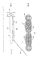
- Figure 1 is a side view of a water current power energy generation system according to one example embodiment of the invention.
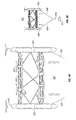
- Figure 2 is a front view of a water current power energy generation system according to a second example embodiment of the invention.
- Figure 3 is a plan view of a ballast tube having a plurality of labyrinth type isolation chambers according to a third embodiment of the invention.
- Figure 4A is a top view of a water current power energy generation system according to a fourth example embodiment of the invention.
- Figure 4B is a top view of the example embodiment depicted in Figure 4A , further including an associated tether anchoring system.
- Figure 5 is a front view of an example propeller system embodiment suitable for use in connection with a submerged or waterborne power generation system.
- Figure 6 is a perspective view of the example propeller system embodiment depicted in Figure 5 , with a detailed portion of the system isolated for additional perspective.
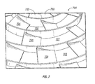
- Figure 7 is an isolated view of a portion of the example propeller system embodiment depicted in Figures 5 and 6 .
- Figure 8 is a side view of an example water current power generation system further comprising a drag mounted propeller array.
- Figure 9 is a rear view of the example water current power generation system depicted in Figure 8 , wherein an even number of propellers facilitate offsetting rotational forces in a drag mounted array.
- Figure 1 depicts a first example embodiment of a water current power 10 generation system 101.
- the system comprises a flotation tube 102, a ballast tube 103, and an induction type power generation unit 104 equipped with a propeller 105.
- Figure. 1 appears to depict only a single flotation tube 102, ballast unit 103 and generator component 104, it is in fact a side view of a larger system, and commercial embodiments comprising multiple tubes and generator components are presently contemplated and described below. Nonetheless, those of skill in the pertinent arts will readily appreciate that description of a limited system with singular elements is illustrative, and will not limit the scope of the subject matter disclosed herein.
- the novelty of the system lies in the induction type power generation unit 104, 20 which lends simplicity and reliability to operations, and produces power that can be output either with or without transformation as an alternating current (AC) to an associated relay station (not shown).
- the system is therefore capable of producing AC power on a commercially viable scale that can be easily sold to and used by a neighboring electrical grid.
- induction generators are mechanically and electrically simpler than other types of synchronous electrical power generators or direct current (DC) generators. 5 They also tend to be more rugged and durable, and usually require neither brushes nor commutators.
- an electrical three-phase asynchronous (e.g ., cage wound) induction machine will, when operated slower than its synchronous speed, function as a motor; the same device, however, when operated faster than its synchronous speed, will function as an induction generator.
- asynchronous e.g ., cage wound
- induction generators can be used to produce alternating electrical power when an internal shaft is rotated faster than the synchronous frequency.
- the shaft rotation is accomplished by means of an associated propeller 105 disposed in a relatively fast moving water current.
- Power derived from the system will, in most cases, be intended to supplement a neighboring power grid system, and thus the operating frequencies of the grid will dictate the frequency of operation for the power generation system. For example, many large power grid systems currently employ a nominal operating frequency of between 50 and 60 Hertz.
- Induction generators are not self-exciting, however, so they require either an external power supply (as could easily be obtained from the neighboring grid using an umbilical run either through the water or beneath an associated seafloor) or else "soft started” by means of a reduced voltage starter in order to produce an initial rotation magnetic flux.
- Reduced voltage starters can lend important advantages to the system, such as quickly determining appropriate operational frequencies, and permitting an unpowered restart in the event the attendant power grip is deactivated for some reason, for example, as a result of damage caused by a hurricane.
- the flotation tube 102 illustrated in Figure 1 comprises a cylindrical body portion disposed in mechanical communication with at least one end cap unit 104 that houses the aforementioned induction generators.
- the generators and associated end cap housings contain a drive shaft and, in some embodiments, related planetary gearing for propeller 105.
- flotation tube 102 comprises a cubical or hexagonal shape, though effective practice of the invention will admit to other geometries as well.
- flotation tube 102 is approximately cylindrical, and pressurized with gas (e.g ., air or another safe, buoyant gas) so that, when the system is restrained by anchored tether 106, the combined forces will constitute the primary lifting force for the ocean current energy generating system.
- gas e.g ., air or another safe, buoyant gas
- the system can be raised to the surface for maintenance or inspection by turning off the generators, thereby reducing drag on the system, which allows the system to rise somewhat toward the surface.
- the flotation tube(s) and/or evacuating fluid from the ballast tube(s) the unit can be safely and reliably floated to the surface so that maintenance or inspection can be performed.
- tether 106 can also be released, so that the floating structure can be towed or otherwise powered toward land or another operating site.
- FIG. 2 is a front view of the power generation system 201, equipped with a plurality of relatively large, slow moving propellers 206 disposed in mechanical communication with the shaft members of induction generator units 204 and 205.
- the generator units are disposed within end cap units housed within flotation tubes 402, 403, as well as across the span of a lattice type body portion of the system disposed between the flotation tubes.
- FIG. 3 a detailed view of the inside of the ballast tubes previously depicted as item 103 in Figure 1 is provided, in which a plurality of labyrinth type isolation chambers are joined in such a manner that separation and mixture of various gases and liquids can be used to permit much finer control of the balance and flotational forces present in the system that can be obtained by means of floatation tubes 102.
- an interior ballast system 301 formed within a ballast tube comprises an air control source 302 disposed in fluid communication with an overpressure check valve and a first isolation chamber 303.
- First isolation chamber 303 contains both a dry gas (e.g ., air having a pressure equal to the surrounding outside water pressure) present in an upper portion of the chamber, and a fluid (e.g ., seawater drawn in from outside the isolation chamber) present in a lower portion of the chamber.
- First isolation chamber 303 also comprises a secondary air feed line 305 for 15 distributing air to other gas-filled compartments of the structure, as well as lines for mixtures of gas and fluid from first isolation chamber 303 to second isolation chamber 304.
- Second isolation chamber 304 in turn comprises an upper portion containing air and a lower portion containing water or the like, which are separated by an isolation cylinder.
- the isolation cylinder contains sea water upon which floats a 20 barrier fluid in order to ensure better isolation between the air and seawater.
- first or second isolation chambers 303, 304 is equipped with instrumentation (e.g ., pressure sensors or differential pressure sensors) to determine whether fluid or air is present in a particular cavity of the system.
- instrumentation e.g ., pressure sensors or differential pressure sensors
- such sensors are input into a logical control system (not shown) used to assist in the detection and control of balance and thrust related measurements.
- a final isolation chamber 306 which, in the depicted embodiment, comprises an air outlet valve 309 used to let air out of the system and, in some circumstances, water into the system.
- a pressure safety valve 307 is provided in the event internal pressures become so great that venting of pressure is required in order to maintain the integrity of system control, and an open water flow valve 308 fitted with a screen to prevent accidental entry by sea creatures is disposed in a lower portion of the isolation tank 306.
- barrier fluids and the like can be used to reduce interaction between air 15 and water, and if the system is fitted with a float control floating on top of the sea water, the barrier fluid can be retained after all of the sea water is expelled.
- Figure 4A presents a top view of one embodiment of the system 401, which in this instance comprises a first flotation tube 402 and a second flotation tube 403; a connecting, lattice like body portion 404 disposed there between; a plurality of induction generators 405, 406 positioned strategically around the floatation tubes and the body portions; a plurality of propellers 407 disposed in mechanical communication with the generators; and a plurality of tethering members 408, 409 disposed in mechanical communication with the flotation tubes 402, 403.
- tethering members 408 and 409 are joined to form a single anchoring tether 410 that is affixed in a known manner to anchoring member 411.
- anchoring tether 410 further comprises means for variably restraining and releasing the system.
- anchoring tether 410 terminates at an anchoring member 411 equipped with a tether termination device (not shown).
- Anchoring member 411 comprises any type of known anchor (e.g ., a dead-weight anchor or the like) suitable for maintaining a fixed position in fast moving currents, which are usually found in locations with rocky seafloors due to soil erosion caused by the fast moving currents.
- this portion of the station can be secured by attaching anchoring tether 410 to either a surface vessel or another ocean current energy generating device, or to another central mooring location such as a floating dynamic positioning buoy.
- Figures 5 - 7 depict several specific (though non-limiting) example embodiments of a propeller system suitable for use with the water current power generation system disclosed herein.
- Those of ordinary skill in the pertinent arts will also appreciate, however, that while the example propeller systems disclosed herein are described with reference to a water current power generation system driven by an induction-type power generator, the example propeller systems can also be used in connection with other types of submerged or waterborne power generation systems to achieve many of the same advantages taught herein.
- Figure 5 is a front view of an example propeller system embodiment suitable for use in connection with a submerged or waterborne power generation system.
- propeller 501 comprises a plurality of alternating fin sets and enclosing rings, which will hereinafter be referred to as a "fin-ring" configuration.
- fin-ring propellers would typically be designed to specification for each particular application, and improved efficiency will be realized by tailoring the diameter, circumference, fin curvature and disposition eccentricity, material selections, etc., based on the operational frequencies required by the induction generators, the speed of surrounding water currents, environmental considerations (e.g ., whether the propellers should have openings or voids through which fish or other aquatic life may pass), and so on.
- neighboring sets of propellers can be rotated in opposite directions ( e.g ., either clockwise or counterclockwise, as representatively depicted in Figure 2 ) in order to promote the creation of eddies or dead zones in front of the propellers, which can repel or help protect marine life, enhance propeller rotation efficiency, etc.
- propeller 501 is disposed 5 around a hub or shaft portion 502 that both holds the propeller 501 in a secure and reliable manner (e.g ., by means of mechanical affixation, such as by means of encapsulated rust-resistant fasteners, welding a propeller body or multiple pieces of a propeller body to a shaft into a single unitary whole, etc.) and imparts a rotational torque proportional to the angular momentum of the rotating propeller onto the shaft for delivery to the power generator.
- hub or shaft portion 502 further comprises a flotation means used to improve the mechanical connection of the Fin-Ring propeller to the shaft.
- drive shafts appropriate for this task currently exist in the art of record, and may comprise, for example, a series of gears and/or clutches, breaking systems, etc., as would be required to effectively communicate the propeller's rotational torque to the generator shaft.
- a retaining fastener such as a bolt and washer assembly or the like is removed from the end of a drive shaft, the fin-ring propeller structure is slipped over the exposed shaft, and then the fastener is replaced, thereby mechanically affixing the fin-ring structure to the shaft.
- the fastener would then be covered by a water-tight cover or the like as representatively depicted in Figure 6 , item 601.
- a central hub comprises the connection point mechanical communication with a large shaft, which can be either installed or removed and replaced as a single structure so that the propeller can be easily serviced and maintained while in the water.
- the hub further comprises a fixed flotation means in order to resist the overhanging load of the shaft and propeller assembly.
- the propellers especially the front propellers in a submerged system, which absorb most of the force of the water current
- the exemplary embodiment of the fin-ring design depicted herein is generally similar across a multitude of other, related embodiments suitable for practice within the system.
- the hub attachment assembly 502 is concentrically surrounded by a first ring member 503, beyond which ( i.e ., further out from the hub assembly) is a second ring member 506.
- Disposed between first ring member 503 and second ring member 506 is a plurality of fin members 504, each of which is separated by a gap 505.
- the gap space between fin members 504 will vary by application, but as a general matter the gaps between fins will increase in size from the inner most ring (in which the gaps are typically the smallest) to the outermost rings (where the gap space is 20 the largest).
- Other configurations admit to gaps of similar sizes, or even larger gaps on inner rings than on outer rings, but an advantage of a mostly solid inner ring surface, wherein most of the entirety of the ring's possible surface area is utilized by fins rather than gaps, is that the structure will tend to force fluid pressure away from the center of the structure toward the outermost rings and beyond the perimeter of the device altogether.
- This approach helps the propeller rotate more easily, and greatly improves the environmental safety of the device by forcing small marine life and the like that might come near the structure toward the outside of the system so that they can either avoid the propeller structure altogether, or else pass through one of the larger gaps in the outer rings. Since resistance against the structure is reduced and greater rotational torque is transmitted to the drive shafts with less drag and loss, the propeller can also be rotated very slowly (for example, in one example embodiment generating satisfactory field results, the propeller rotates at a speed of only 8 RPM)., further ensuring that marine life will be able to avoid the structure and enhancing environmental neutrality and safety. The slow rotational speeds also make the system more rugged and durable and less likely to suffer damage if contacted by debris or a submerged object floating nearby.
- the gap spaces 514 of the outermost ring are the largest gap spaces in the system, and separate fins 513 to the system's greatest extent.
- a final ring member 515 encloses the outer periphery of the propeller system, again enhancing its environmental friendliness, as fish and other marine life inadvertently striking the outside ring 515 will encounter only a slight glancing blow against a slowly-moving structure, which further increases marine safety by pushing water and fluid pressures away from the device as much as possible.
- the pitch of fins 602 measured relative to the plane of the fin-ring assembly can be altered (for example, the rings can be disposed with greater eccentricity) as their position within the assembly is advanced from the first ring surrounding the central hub toward the outermost rings.
- Disposing fins 602 at a flatter pitch within the interior rings and more eccentrically (i.e ., in a plane more perpendicular to the assembly plane) in the outer rings will tend to flatten and smooth the water flow around the propeller, thereby achieving superior fluid flow characteristics (which minimizes system vibration), creating less resistance against the propeller structure, and providing a greater surrounding centrifugal fluid force to assure that marine life avoids the center of the propeller system.
- a series of curved fins 702, 704, 706, 708 are 15 disposed between gaps 703, 705, 707, 709 of increasing size (note that the center attachment hub from which the smallest concentric rings originate would be located beyond the top of the Figure, e.g ., above fin 702 and gap 703).
- fins 702, 704, 706, 708 are also disposed with greater eccentricity as they are installed further and further from the hub, so that the disposition angle of fin 708 measured relative to the assembly plane would be greater than that of fins 702, 704, 706 disposed neared the center attachment hub.
- a tethered, submerged water current power generation system in which the entire propeller array is drag mounted, so that power interference from a front mounted array is avoided, and greater system stability and power efficiency is achieved.
- this particular configuration admits to one or more propellers disposed in both an tipper drag mount position and a lower drag mount position, though disposition of multiple propeller arrays in an either greater or fewer number of levels is also possible.
- Figure 9 which is essentially a rear view of the alternative embodiment depicted in Figure 8 , it is seen that one specific (though non-limiting) embodiment comprises a propeller array having ten total propellers, with six propellers being disposed in a lower drag mount position, and four propellers being disposed in an upper drag mounted position, with the upper position array being further distributed with two propellers on each side of the power generation system.
- This particular embodiment has been found to admit to superior power generation characteristics, while stabilizing the attendant system structure by minimizing vibration, and allowing evenly matched pairs of propellers to run in opposite rotational directions. While such configurations are optimal for certain embodiments of the power generation system, a virtually limitless number of other arrays and disposition configurations can instead be employed when deemed effective in a given operations environment.
- the composition of the entire fin-ring propeller structure would likely be common, for example, all made from a durable, coated or rust-resistant, lightweight metal.
- differing material compositions as between fins and rings is also possible, and other materials such as metallic composites, hard carbon composites, ceramics, etc., is certainly possible without departing from the scope of the invention as claimed.
- the water current power generation system of example 1 further comprising a plurality of flotation chambers joined by a body structure.
- the water current power generation system of example 6 further comprising a plurality of propellers disposed in mechanical communication with said one or more induction type generator units.
- ballast chamber further comprises one or more labyrinth type isolation chambers.
- a water current power generation system comprising: a plurality of flotation tubes joined by a body structure; a plurality of ballast chambers joined by a body structure; a plurality of induction type power generation units disposed within housings associated with one or more of said flotation chambers, ballast chambers and body structure; and a plurality of propellers disposed in communication with said induction type generator units, wherein said plurality of propellers further comprise one or more concentrically disposed rings, said concentrically disposed rings having an inner ring 1 member, an outer ring member, and a plurality of curved fin members separated by gap spaces disposed between said inner and outer ring members.
- Propeller system for submerged or waterborne structures comprising; a hub member for disposing a propeller in communication with a drive system; and a propeller member having one or more concentrically disposed rings, said concentrically disposed rings having an inner ring member, an outer ring member, and a plurality of curved fin members separated by gap spaces disposed between said inner ring member and said outer ring member.
Landscapes
- Engineering & Computer Science (AREA)
- Power Engineering (AREA)
- Chemical & Material Sciences (AREA)
- Combustion & Propulsion (AREA)
- Mechanical Engineering (AREA)
- General Engineering & Computer Science (AREA)
- Other Liquid Machine Or Engine Such As Wave Power Use (AREA)
Applications Claiming Priority (2)
| Application Number | Priority Date | Filing Date | Title |
|---|---|---|---|
| US25935909P | 2009-11-09 | 2009-11-09 | |
| US12/702,546 US20110109090A1 (en) | 2009-11-09 | 2010-02-09 | Fin-Ring Propeller For A Water Current Power Generation System |
Publications (3)
| Publication Number | Publication Date |
|---|---|
| EP2320069A2 true EP2320069A2 (fr) | 2011-05-11 |
| EP2320069A3 EP2320069A3 (fr) | 2011-10-19 |
| EP2320069B1 EP2320069B1 (fr) | 2013-01-23 |
Family
ID=42556478
Family Applications (2)
| Application Number | Title | Priority Date | Filing Date |
|---|---|---|---|
| EP10169625A Active EP2320070B1 (fr) | 2009-11-09 | 2010-07-15 | Roue annulaire mobile pour centrale hydroéléctrique |
| EP10169624A Active EP2320069B1 (fr) | 2009-11-09 | 2010-07-15 | Système de génération d'énergie à base du courant d'eau |
Family Applications Before (1)
| Application Number | Title | Priority Date | Filing Date |
|---|---|---|---|
| EP10169625A Active EP2320070B1 (fr) | 2009-11-09 | 2010-07-15 | Roue annulaire mobile pour centrale hydroéléctrique |
Country Status (15)
| Country | Link |
|---|---|
| US (3) | US20110109090A1 (fr) |
| EP (2) | EP2320070B1 (fr) |
| JP (2) | JP5050077B2 (fr) |
| KR (2) | KR101192140B1 (fr) |
| AP (2) | AP3857A (fr) |
| AU (2) | AU2010200574B1 (fr) |
| BR (2) | BRPI1001623B1 (fr) |
| DK (2) | DK2320070T3 (fr) |
| EA (2) | EA014951B1 (fr) |
| ES (2) | ES2401368T3 (fr) |
| MX (2) | MX2010002907A (fr) |
| PT (2) | PT2320069E (fr) |
| TW (2) | TWI481779B (fr) |
| WO (1) | WO2011056249A2 (fr) |
| ZA (2) | ZA201001423B (fr) |
Families Citing this family (39)
| Publication number | Priority date | Publication date | Assignee | Title |
|---|---|---|---|---|
| WO2009026620A1 (fr) | 2007-08-24 | 2009-03-05 | Fourivers Power Engineering Pty Ltd | Appareil de génération d'énergie marine utilisant les courants océaniques |
| WO2010008368A1 (fr) * | 2008-07-16 | 2010-01-21 | Anadarko Petroleum Corporation | Système de génération d'énergie par courant d'eau |
| US8847421B2 (en) | 2008-07-16 | 2014-09-30 | Anadarko Petroleum Corporation | Subsystems for a water current power generation system |
| US20110109090A1 (en) * | 2009-11-09 | 2011-05-12 | Bolin William D | Fin-Ring Propeller For A Water Current Power Generation System |
| AU2012213966B2 (en) * | 2010-02-17 | 2015-01-15 | Anadarko Petroleum Corporation | Subsystems for a water current power generation system |
| US8558403B2 (en) * | 2010-09-27 | 2013-10-15 | Thomas Rooney | Single moored offshore horizontal turbine train |
| US8653682B2 (en) * | 2010-09-27 | 2014-02-18 | Thomas Rooney | Offshore hydroelectric turbine assembly and method |
| JP5681459B2 (ja) * | 2010-11-25 | 2015-03-11 | 川崎重工業株式会社 | 水流発電装置 |
| KR101106764B1 (ko) * | 2011-05-16 | 2012-01-18 | 이명훈 | 부상식 수력발전장치 |
| TW201309908A (zh) * | 2011-08-19 | 2013-03-01 | Univ Nat Pingtung Sci & Tech | 複合載具型風能收集裝置 |
| DE102011112483A1 (de) * | 2011-09-03 | 2013-03-07 | Robert Bosch Gmbh | Ausrichtung eines Wellenenergiekonverters zur Umwandlung von Energie aus einer Wellenbewegung eines Fluids in eine andere Energieform |
| WO2013162520A2 (fr) * | 2012-04-24 | 2013-10-31 | Anadarko Petroleum Corporation | Sous-systèmes pour un système de production d'énergie par des courants d'eau |
| US8766471B2 (en) * | 2012-09-17 | 2014-07-01 | Francisco Orea | Energy generation apparatus for ships |
| JP2014058911A (ja) * | 2012-09-18 | 2014-04-03 | Okinawa Institute Of Science And Technology Graduate Univ | 水流発電装置 |
| JP6142992B2 (ja) * | 2013-04-22 | 2017-06-07 | 株式会社Ihi | 海流発電装置 |
| CL2013001238A1 (es) * | 2013-05-03 | 2013-08-16 | Pavez Vasquez Claudio Marcelo | Dispositivo de soporte y fijacion sumergible para equipamiento de generacion electrica, conformado por una capsula hermetica en cuyo interior permite la instalacion de equipamiento de control, motor generador y tablero electrico, la capsula se une a una estructura de flotacion rigida conformada por estructuras tubulares de boyantes que poseen camaras estanco inundables y de aire comprimido, valvulas y un sistema de comunicacion. |
| CN203601542U (zh) | 2013-08-06 | 2014-05-21 | 杭州林黄丁新能源研究院有限公司 | 潮流发电装置及其安装框架 |
| US9334847B2 (en) | 2013-12-23 | 2016-05-10 | Grover Curtis Harris | Bi-rotational generator |
| TWI580861B (zh) * | 2014-01-08 | 2017-05-01 | 劉文晏 | 洋流發電機組 |
| WO2016025038A1 (fr) * | 2014-08-12 | 2016-02-18 | Anadarko Petroleum Corporation | Système et procédés de transport et de maintenance d'un système de production d'énergie hydraulique |
| TWI582310B (zh) * | 2014-12-04 | 2017-05-11 | 朝陽科技大學 | 海流發電裝置 |
| KR101599708B1 (ko) * | 2015-03-18 | 2016-03-04 | 이동인 | 잠수형 발전 플랫폼 |
| GB201517525D0 (en) * | 2015-10-05 | 2015-11-18 | Coman Christopher J A | Apparatus and method of generating energy from renewable energy sources |
| WO2017065782A1 (fr) * | 2015-10-16 | 2017-04-20 | Augustine Chan | Turbinateur |
| IT201600094920A1 (it) * | 2016-09-21 | 2018-03-21 | N T A S R L | Sistema di ancoraggio perfezionato per un generatore di energia elettrica sottomarino e relativo impianto di produzione di energia elettrica sottomarino |
| US9745951B1 (en) * | 2016-11-07 | 2017-08-29 | Robert E. Doyle | Self-positioning robotic subsea power generation system |
| KR102011196B1 (ko) * | 2017-06-20 | 2019-08-14 | 최준서 | 잠수함 탐지용 소나 |
| KR102011197B1 (ko) * | 2017-06-20 | 2019-08-14 | 최준서 | 잠수함 탐지용 소나 |
| US11701616B2 (en) | 2017-09-22 | 2023-07-18 | Dehlsen Associates Of The Pacific Limited | Sorbent emitter for direct air capture of carbon dioxide |
| DK179738B1 (en) | 2017-10-11 | 2019-04-30 | Ravn Niels | Wind-Driven Energy Converting Device |
| CN108590927B (zh) * | 2018-05-25 | 2023-09-22 | 江苏科技大学 | 一种浮式水下球型串列多振子发电装置 |
| PT3604793T (pt) * | 2018-08-03 | 2021-07-30 | Ge Renewable Tech | Perfis interpás para turbinas hidráulicas com peça de cobertura removível |
| RU188371U1 (ru) * | 2018-12-27 | 2019-04-09 | федеральное государственное бюджетное образовательное учреждение высшего образования "Национальный исследовательский университет "МЭИ" (ФГБОУ ВО "НИУ "МЭИ") | Низконапорная гидравлическая турбина |
| AU2020236379B2 (en) * | 2019-03-08 | 2023-08-17 | Big Moon Power, Inc. | Systems and methods for hydro-based electric power generation |
| FR3110941A1 (fr) * | 2020-05-28 | 2021-12-03 | Airbus (S.A.S.) | Dispositif de production d’énergie comportant un bateau aérotracté tractant au moins une hydrolienne |
| CN114151270B (zh) * | 2022-01-07 | 2024-02-27 | 江苏科技大学 | 一种具有压浪减摇及波浪能发电功能的浮式防波堤 |
| CN114893338B (zh) * | 2022-04-29 | 2023-04-25 | 上海交通大学 | 基于液压系统将波浪能输出为稳定电能的系泊装置 |
| US20240263605A1 (en) * | 2023-02-07 | 2024-08-08 | Energy Vault, Inc. | System for generating electricity from an underwater ocean stream |
| CN117432568B (zh) * | 2023-12-21 | 2024-03-08 | 大庆市普罗石油科技有限公司 | 一种基于油田高压注水配水单井管道水的余压发电系统 |
Family Cites Families (77)
| Publication number | Priority date | Publication date | Assignee | Title |
|---|---|---|---|---|
| US1350187A (en) * | 1918-09-02 | 1920-08-17 | John C Streibich | Submersible water-power device |
| US1441788A (en) * | 1920-04-29 | 1923-01-09 | Coninck Marcel De | Multiple-blade helicoidal propeller |
| US1739866A (en) * | 1925-04-25 | 1929-12-17 | Schuh Franz | Wind and water wheel |
| US2501696A (en) * | 1946-01-12 | 1950-03-28 | Wolfgang Kmentt | Stream turbine |
| US3222533A (en) * | 1963-08-01 | 1965-12-07 | James E Mackay | Windmill generator |
| DE2211333A1 (de) * | 1972-03-09 | 1973-09-13 | Rheinmetall Gmbh | Unterwasser-messbojensystem |
| US3986787A (en) * | 1974-05-07 | 1976-10-19 | Mouton Jr William J | River turbine |
| US4383182A (en) * | 1975-06-11 | 1983-05-10 | Bowley Wallace W | Underwater power generator |
| DE2852554C2 (de) * | 1978-12-05 | 1983-01-20 | Alberto 8131 Berg Kling | Rotor für eine Strömungsmaschine |
| DE2909781A1 (de) * | 1979-03-13 | 1980-09-25 | Karlheinz Ohlberg | Fluegelrotor, insbesondere fuer windmotoren (windkraftwerke) mit in mindestens 2 konzentrisch aufgeteilte kreisringflaechen |
| US4330714A (en) * | 1980-06-26 | 1982-05-18 | Smith Otto J M | Wind turbine system |
| JPS58162299U (ja) * | 1982-04-26 | 1983-10-28 | 日産自動車株式会社 | 冷却フアン |
| US4613279A (en) * | 1984-03-22 | 1986-09-23 | Riverside Energy Technology, Inc. | Kinetic hydro energy conversion system |
| US4720640A (en) * | 1985-09-23 | 1988-01-19 | Turbostar, Inc. | Fluid powered electrical generator |
| DK155454C (da) * | 1986-12-03 | 1989-08-07 | Hans Marius Pedersen | Flydende vandkraftvaerk til anbringelse i hav- og flodstroemme for energiindvirkning |
| US4850190A (en) * | 1988-05-09 | 1989-07-25 | Pitts Thomas H | Submerged ocean current electrical generator and method for hydrogen production |
| US4863350A (en) * | 1988-11-18 | 1989-09-05 | Quarterman Edward A | Air turbine |
| JP2652051B2 (ja) * | 1988-11-28 | 1997-09-10 | 本田技研工業株式会社 | 船舶推進装置 |
| US5096382A (en) * | 1989-05-17 | 1992-03-17 | Gratzer Louis B | Ring-shrouded propeller |
| US5292088A (en) * | 1989-10-10 | 1994-03-08 | Lemont Harold E | Propulsive thrust ring system |
| US5592816A (en) * | 1995-02-03 | 1997-01-14 | Williams; Herbert L. | Hydroelectric powerplant |
| US5599172A (en) * | 1995-07-31 | 1997-02-04 | Mccabe; Francis J. | Wind energy conversion system |
| US5910688A (en) * | 1997-05-12 | 1999-06-08 | Li; Wan-Tsai | Windmill |
| EP0931931A1 (fr) * | 1998-01-27 | 1999-07-28 | Entry-Technology | Système magnétohydrodynamique à partir de courants marines |
| US6091161A (en) * | 1998-11-03 | 2000-07-18 | Dehlsen Associates, L.L.C. | Method of controlling operating depth of an electricity-generating device having a tethered water current-driven turbine |
| FR2793528B1 (fr) * | 1999-05-12 | 2001-10-26 | Cie Internationale Des Turbine | Eolienne a pales obliques et generateur electrique |
| NL1013559C2 (nl) * | 1999-11-11 | 2001-05-28 | Peter Alexander Josephus Pas | Systeem voor het uit water produceren van waterstof onder gebruikmaking van een waterstroom zoals een golfstroom of getijdenstroom. |
| JP3530872B2 (ja) * | 2000-03-01 | 2004-05-24 | 正晃 長島 | 水力エネルギー変換装置 |
| US6648589B2 (en) * | 2000-09-19 | 2003-11-18 | Herbert Lehman Williams | Hydroelectric turbine for producing electricity from a water current |
| US6729840B2 (en) * | 2001-02-06 | 2004-05-04 | Herbert L. Williams | Hydroelectric powerplant |
| US6531788B2 (en) * | 2001-02-22 | 2003-03-11 | John H. Robson | Submersible electrical power generating plant |
| EP1467093A1 (fr) * | 2001-07-11 | 2004-10-13 | Hydra Tidal Energy Technology AS | Générateur pour turbine à courant d'eau munie de rotors coaxiaux contrarotatifs |
| CN1636111B (zh) | 2001-09-17 | 2010-05-26 | 净流有限合伙企业 | 水力涡轮发电机装置 |
| US6692319B2 (en) * | 2002-03-29 | 2004-02-17 | Alstom Shilling Robotics | Thruster for submarine vessels |
| GB0227739D0 (en) * | 2002-11-28 | 2003-01-08 | Marine Current Turbines Ltd | Supporting structures for water current (including tidal stream) turbines |
| GB0229042D0 (en) * | 2002-12-13 | 2003-01-15 | Marine Current Turbines Ltd | Hydraulic speed-increasing transmission for water current powered turbine |
| GB0306075D0 (en) * | 2003-03-18 | 2003-04-23 | Renewable Devices Ltd | Wind turbine |
| GB0306809D0 (en) * | 2003-03-25 | 2003-04-30 | Marine Current Turbines Ltd | Water current powered turbines installed on a deck or "false seabed" |
| NO320252B1 (no) * | 2003-05-21 | 2005-11-14 | Hydra Tidal Energy Technology | Anordning for forankring av en flytende struktur |
| US20060266038A1 (en) * | 2003-05-29 | 2006-11-30 | Krouse Wayne F | Machine and system for power generation through movement of water |
| US8072089B2 (en) * | 2003-05-29 | 2011-12-06 | Krouse Wayne F | Fluid energy apparatus and method |
| US6955049B2 (en) * | 2003-05-29 | 2005-10-18 | Krouse Wayne F | Machine and system for power generation through movement of water |
| WO2005060381A2 (fr) * | 2003-06-25 | 2005-07-07 | Advanced Propulsion Technologies | Generateur annulaire |
| US6956300B2 (en) * | 2003-08-04 | 2005-10-18 | Andrew Roman Gizara | Gimbal-mounted hydroelectric turbine |
| US7220096B2 (en) * | 2004-03-16 | 2007-05-22 | Tocher Angus J | Habitat friendly, multiple impellor, wind energy extraction |
| US6887031B1 (en) * | 2004-03-16 | 2005-05-03 | Angus J. Tocher | Habitat friendly, pressure conversion, wind energy extraction |
| FR2869586B1 (fr) * | 2004-04-30 | 2006-06-16 | Alstom Sa | Ensemble de propulsion pour navire, comprenant une nacelle destinee a une installation sous la carene du navire |
| JP2005351201A (ja) * | 2004-06-11 | 2005-12-22 | Mitsubishi Heavy Ind Ltd | 潮流発電設備 |
| NO321763B1 (no) * | 2004-08-25 | 2006-07-03 | Wave Energy As | Anordning ved turbin |
| CA2640643C (fr) * | 2004-09-17 | 2011-05-31 | Clean Current Power Systems Incorporated | Augmentation de debit pour turbogeneratrice sous-marine |
| FR2878000B1 (fr) * | 2004-11-15 | 2010-01-01 | Philippe Boisneau | Centrale flottante hydraulique autonome de production d'electricite a turbine immergee, en eau douce, saumatre ou salee, de surface ou dans la masse d'eau |
| GB0425303D0 (en) * | 2004-11-17 | 2004-12-15 | Overberg Ltd | Floating apparatus for deploying in a marine current for gaining energy |
| GB0427197D0 (en) * | 2004-12-11 | 2005-01-12 | Johnston Barry | Tidal power generating apparatus |
| US7323792B2 (en) * | 2005-05-09 | 2008-01-29 | Chester Sohn | Wind turbine |
| GB2434410B (en) * | 2006-01-18 | 2009-09-16 | Michael Torr Todman | Underwater turbine mounting |
| WO2007100639A2 (fr) * | 2006-02-28 | 2007-09-07 | Kuehnle Manfred R | Équipement de turbines immergées |
| JP4773850B2 (ja) * | 2006-03-08 | 2011-09-14 | 三菱重工業株式会社 | 風力発電システム、及び風力発電システムの非常用電力供給方法 |
| TWM299220U (en) * | 2006-03-14 | 2006-10-11 | Univ Nat Penghu | Offshore type wave power electricity generator |
| US7291936B1 (en) * | 2006-05-03 | 2007-11-06 | Robson John H | Submersible electrical power generating plant |
| US7530391B2 (en) * | 2006-05-31 | 2009-05-12 | Baker Hughes Incorporated | Seal section for electrical submersible pump |
| US7489046B2 (en) * | 2006-06-08 | 2009-02-10 | Northern Power Systems, Inc. | Water turbine system and method of operation |
| US7682126B2 (en) * | 2006-06-09 | 2010-03-23 | David Joseph Parker | Tethered propgen |
| DE102007013293B3 (de) * | 2007-03-16 | 2008-06-26 | Voith Patent Gmbh | Verfahren und Vorrichtung zum Betrieb eines Unterwasserkraftwerks |
| US7980832B2 (en) * | 2007-04-19 | 2011-07-19 | Ahdoot Ned M | Wave energy converter |
| US7525211B2 (en) * | 2007-06-19 | 2009-04-28 | Marvin Russell H | Control system for twin turbine wind power generating system |
| WO2009009375A1 (fr) * | 2007-07-06 | 2009-01-15 | Kkr Ip Limited Liability Company | Éolienne modulaire, éolienne à turbines multiples, système informatique pour éolienne, et leur procédé d'utilisation |
| WO2009026620A1 (fr) * | 2007-08-24 | 2009-03-05 | Fourivers Power Engineering Pty Ltd | Appareil de génération d'énergie marine utilisant les courants océaniques |
| US20090096217A1 (en) * | 2007-10-15 | 2009-04-16 | William Kemper Watson | Wind turbine with perimeter power takeoff |
| US8102071B2 (en) * | 2007-10-18 | 2012-01-24 | Catlin Christopher S | River and tidal power harvester |
| US20090167026A1 (en) * | 2007-12-28 | 2009-07-02 | Russel Hugh Marvin | Inlet passageway and sealing in a turbine wind power generating system |
| JP4982828B2 (ja) | 2008-01-23 | 2012-07-25 | 独立行政法人海上技術安全研究所 | 潮流・海流発電装置 |
| EP2088311B1 (fr) * | 2008-02-05 | 2015-10-14 | OpenHydro Group Limited | Turbine hydroélectrique avec rotor flottant |
| US20090257863A1 (en) | 2008-04-11 | 2009-10-15 | Asia Power Dev. Foundation, Inc. | Turbine assembly |
| WO2010008368A1 (fr) * | 2008-07-16 | 2010-01-21 | Anadarko Petroleum Corporation | Système de génération d'énergie par courant d'eau |
| US20110109090A1 (en) * | 2009-11-09 | 2011-05-12 | Bolin William D | Fin-Ring Propeller For A Water Current Power Generation System |
| EP2199602A1 (fr) * | 2008-12-18 | 2010-06-23 | OpenHydro IP Limited | Procédé de sécurisation d'une turbine hydroélectrique sur un site de déploiement et une turbine hydroélectrique |
| US20100164230A1 (en) * | 2008-12-29 | 2010-07-01 | Sidney Irving Belinsky | Installation for harvesting ocean currents (IHOC) and methods and means for its delivery, installation and servicing |
-
2010
- 2010-02-09 US US12/702,546 patent/US20110109090A1/en not_active Abandoned
- 2010-02-09 WO PCT/US2010/023598 patent/WO2011056249A2/fr active Application Filing
- 2010-02-17 AU AU2010200574A patent/AU2010200574B1/en active Active
- 2010-02-26 ZA ZA2010/01423A patent/ZA201001423B/en unknown
- 2010-03-02 AP AP2010005184A patent/AP3857A/en active
- 2010-03-02 AP AP2010005329A patent/AP3779A/en active
- 2010-03-03 TW TW099117971A patent/TWI481779B/zh active
- 2010-03-03 TW TW099106210A patent/TWI486519B/zh active
- 2010-03-16 MX MX2010002907A patent/MX2010002907A/es active IP Right Grant
- 2010-03-30 EA EA201000412A patent/EA014951B1/ru unknown
- 2010-03-30 EA EA201000528A patent/EA014952B1/ru unknown
- 2010-04-09 AU AU2010201415A patent/AU2010201415A1/en not_active Abandoned
- 2010-04-15 JP JP2010093613A patent/JP5050077B2/ja active Active
- 2010-04-19 MX MX2010004264A patent/MX2010004264A/es active IP Right Grant
- 2010-05-10 BR BRPI1001623-6A patent/BRPI1001623B1/pt active IP Right Grant
- 2010-05-10 KR KR1020100043397A patent/KR101192140B1/ko active IP Right Grant
- 2010-05-10 BR BRPI1005790-0A patent/BRPI1005790B1/pt active IP Right Grant
- 2010-05-17 KR KR1020100045860A patent/KR101237132B1/ko active IP Right Grant
- 2010-05-26 US US12/788,099 patent/US20100232962A1/en not_active Abandoned
- 2010-07-15 EP EP10169625A patent/EP2320070B1/fr active Active
- 2010-07-15 PT PT101696243T patent/PT2320069E/pt unknown
- 2010-07-15 ES ES10169625T patent/ES2401368T3/es active Active
- 2010-07-15 ES ES10169624T patent/ES2404356T3/es active Active
- 2010-07-15 DK DK10169625.0T patent/DK2320070T3/da active
- 2010-07-15 EP EP10169624A patent/EP2320069B1/fr active Active
- 2010-07-15 DK DK10169624.3T patent/DK2320069T3/da active
- 2010-07-15 PT PT101696250T patent/PT2320070E/pt unknown
- 2010-09-15 ZA ZA2010/06620A patent/ZA201006620B/en unknown
- 2010-09-17 JP JP2010209551A patent/JP5675243B2/ja active Active
-
2011
- 2011-05-17 US US13/109,451 patent/US8288882B2/en active Active
Non-Patent Citations (1)
| Title |
|---|
| None |
Also Published As
Similar Documents
| Publication | Publication Date | Title |
|---|---|---|
| EP2320069B1 (fr) | Système de génération d'énergie à base du courant d'eau | |
| US8847421B2 (en) | Subsystems for a water current power generation system | |
| EP2657512B1 (fr) | Systèmes de distribution et de transmission de puissance pour un système de génération d'énergie par courant d'eau | |
| EP2985451A1 (fr) | Système et procédé pour le transport et la maintenance d'un système de génération d'énergie par courant d'eau | |
| AU2013201373B2 (en) | Fin-ring propeller for a water current power generation system | |
| AU2012213966B2 (en) | Subsystems for a water current power generation system | |
| AU2014277769B9 (en) | Subsystems for a water current power generation system | |
| OA17018A (en) | Subsystems for a water current power generation system. |
Legal Events
| Date | Code | Title | Description |
|---|---|---|---|
| PUAI | Public reference made under article 153(3) epc to a published international application that has entered the european phase |
Free format text: ORIGINAL CODE: 0009012 |
|
| AK | Designated contracting states |
Kind code of ref document: A2 Designated state(s): AL AT BE BG CH CY CZ DE DK EE ES FI FR GB GR HR HU IE IS IT LI LT LU LV MC MK MT NL NO PL PT RO SE SI SK SM TR |
|
| AX | Request for extension of the european patent |
Extension state: BA ME RS |
|
| RIN1 | Information on inventor provided before grant (corrected) |
Inventor name: BOLIN, WILLIAM D. |
|
| PUAL | Search report despatched |
Free format text: ORIGINAL CODE: 0009013 |
|
| AK | Designated contracting states |
Kind code of ref document: A3 Designated state(s): AL AT BE BG CH CY CZ DE DK EE ES FI FR GB GR HR HU IE IS IT LI LT LU LV MC MK MT NL NO PL PT RO SE SI SK SM TR |
|
| AX | Request for extension of the european patent |
Extension state: BA ME RS |
|
| RIC1 | Information provided on ipc code assigned before grant |
Ipc: F03B 3/12 20060101ALI20110915BHEP Ipc: F03B 17/06 20060101AFI20110915BHEP |
|
| 17P | Request for examination filed |
Effective date: 20120320 |
|
| GRAP | Despatch of communication of intention to grant a patent |
Free format text: ORIGINAL CODE: EPIDOSNIGR1 |
|
| GRAS | Grant fee paid |
Free format text: ORIGINAL CODE: EPIDOSNIGR3 |
|
| GRAA | (expected) grant |
Free format text: ORIGINAL CODE: 0009210 |
|
| AK | Designated contracting states |
Kind code of ref document: B1 Designated state(s): AL AT BE BG CH CY CZ DE DK EE ES FI FR GB GR HR HU IE IS IT LI LT LU LV MC MK MT NL NO PL PT RO SE SI SK SM TR |
|
| REG | Reference to a national code |
Ref country code: GB Ref legal event code: FG4D |
|
| REG | Reference to a national code |
Ref country code: CH Ref legal event code: EP |
|
| REG | Reference to a national code |
Ref country code: AT Ref legal event code: REF Ref document number: 595116 Country of ref document: AT Kind code of ref document: T Effective date: 20130215 Ref country code: CH Ref legal event code: EP |
|
| REG | Reference to a national code |
Ref country code: IE Ref legal event code: FG4D |
|
| REG | Reference to a national code |
Ref country code: DK Ref legal event code: T3 |
|
| REG | Reference to a national code |
Ref country code: DE Ref legal event code: R096 Ref document number: 602010004779 Country of ref document: DE Effective date: 20130321 |
|
| REG | Reference to a national code |
Ref country code: PT Ref legal event code: SC4A Free format text: AVAILABILITY OF NATIONAL TRANSLATION Effective date: 20130327 |
|
| REG | Reference to a national code |
Ref country code: ES Ref legal event code: FG2A Ref document number: 2404356 Country of ref document: ES Kind code of ref document: T3 Effective date: 20130527 |
|
| REG | Reference to a national code |
Ref country code: NO Ref legal event code: T2 Effective date: 20130123 |
|
| REG | Reference to a national code |
Ref country code: NL Ref legal event code: T3 |
|
| REG | Reference to a national code |
Ref country code: AT Ref legal event code: MK05 Ref document number: 595116 Country of ref document: AT Kind code of ref document: T Effective date: 20130123 |
|
| REG | Reference to a national code |
Ref country code: LT Ref legal event code: MG4D |
|
| PG25 | Lapsed in a contracting state [announced via postgrant information from national office to epo] |
Ref country code: SE Free format text: LAPSE BECAUSE OF FAILURE TO SUBMIT A TRANSLATION OF THE DESCRIPTION OR TO PAY THE FEE WITHIN THE PRESCRIBED TIME-LIMIT Effective date: 20130123 Ref country code: BE Free format text: LAPSE BECAUSE OF FAILURE TO SUBMIT A TRANSLATION OF THE DESCRIPTION OR TO PAY THE FEE WITHIN THE PRESCRIBED TIME-LIMIT Effective date: 20130123 Ref country code: IS Free format text: LAPSE BECAUSE OF FAILURE TO SUBMIT A TRANSLATION OF THE DESCRIPTION OR TO PAY THE FEE WITHIN THE PRESCRIBED TIME-LIMIT Effective date: 20130523 Ref country code: LT Free format text: LAPSE BECAUSE OF FAILURE TO SUBMIT A TRANSLATION OF THE DESCRIPTION OR TO PAY THE FEE WITHIN THE PRESCRIBED TIME-LIMIT Effective date: 20130123 Ref country code: BG Free format text: LAPSE BECAUSE OF FAILURE TO SUBMIT A TRANSLATION OF THE DESCRIPTION OR TO PAY THE FEE WITHIN THE PRESCRIBED TIME-LIMIT Effective date: 20130423 Ref country code: AT Free format text: LAPSE BECAUSE OF FAILURE TO SUBMIT A TRANSLATION OF THE DESCRIPTION OR TO PAY THE FEE WITHIN THE PRESCRIBED TIME-LIMIT Effective date: 20130123 |
|
| PG25 | Lapsed in a contracting state [announced via postgrant information from national office to epo] |
Ref country code: LV Free format text: LAPSE BECAUSE OF FAILURE TO SUBMIT A TRANSLATION OF THE DESCRIPTION OR TO PAY THE FEE WITHIN THE PRESCRIBED TIME-LIMIT Effective date: 20130123 Ref country code: PL Free format text: LAPSE BECAUSE OF FAILURE TO SUBMIT A TRANSLATION OF THE DESCRIPTION OR TO PAY THE FEE WITHIN THE PRESCRIBED TIME-LIMIT Effective date: 20130123 Ref country code: SI Free format text: LAPSE BECAUSE OF FAILURE TO SUBMIT A TRANSLATION OF THE DESCRIPTION OR TO PAY THE FEE WITHIN THE PRESCRIBED TIME-LIMIT Effective date: 20130123 Ref country code: GR Free format text: LAPSE BECAUSE OF FAILURE TO SUBMIT A TRANSLATION OF THE DESCRIPTION OR TO PAY THE FEE WITHIN THE PRESCRIBED TIME-LIMIT Effective date: 20130424 |
|
| PG25 | Lapsed in a contracting state [announced via postgrant information from national office to epo] |
Ref country code: HR Free format text: LAPSE BECAUSE OF FAILURE TO SUBMIT A TRANSLATION OF THE DESCRIPTION OR TO PAY THE FEE WITHIN THE PRESCRIBED TIME-LIMIT Effective date: 20130123 |
|
| PG25 | Lapsed in a contracting state [announced via postgrant information from national office to epo] |
Ref country code: RO Free format text: LAPSE BECAUSE OF FAILURE TO SUBMIT A TRANSLATION OF THE DESCRIPTION OR TO PAY THE FEE WITHIN THE PRESCRIBED TIME-LIMIT Effective date: 20130123 Ref country code: EE Free format text: LAPSE BECAUSE OF FAILURE TO SUBMIT A TRANSLATION OF THE DESCRIPTION OR TO PAY THE FEE WITHIN THE PRESCRIBED TIME-LIMIT Effective date: 20130123 Ref country code: CZ Free format text: LAPSE BECAUSE OF FAILURE TO SUBMIT A TRANSLATION OF THE DESCRIPTION OR TO PAY THE FEE WITHIN THE PRESCRIBED TIME-LIMIT Effective date: 20130123 Ref country code: SK Free format text: LAPSE BECAUSE OF FAILURE TO SUBMIT A TRANSLATION OF THE DESCRIPTION OR TO PAY THE FEE WITHIN THE PRESCRIBED TIME-LIMIT Effective date: 20130123 |
|
| PG25 | Lapsed in a contracting state [announced via postgrant information from national office to epo] |
Ref country code: CY Free format text: LAPSE BECAUSE OF FAILURE TO SUBMIT A TRANSLATION OF THE DESCRIPTION OR TO PAY THE FEE WITHIN THE PRESCRIBED TIME-LIMIT Effective date: 20130123 |
|
| PLBE | No opposition filed within time limit |
Free format text: ORIGINAL CODE: 0009261 |
|
| STAA | Information on the status of an ep patent application or granted ep patent |
Free format text: STATUS: NO OPPOSITION FILED WITHIN TIME LIMIT |
|
| 26N | No opposition filed |
Effective date: 20131024 |
|
| REG | Reference to a national code |
Ref country code: DE Ref legal event code: R097 Ref document number: 602010004779 Country of ref document: DE Effective date: 20131024 |
|
| PG25 | Lapsed in a contracting state [announced via postgrant information from national office to epo] |
Ref country code: MC Free format text: LAPSE BECAUSE OF FAILURE TO SUBMIT A TRANSLATION OF THE DESCRIPTION OR TO PAY THE FEE WITHIN THE PRESCRIBED TIME-LIMIT Effective date: 20130123 |
|
| REG | Reference to a national code |
Ref country code: CH Ref legal event code: PL |
|
| PG25 | Lapsed in a contracting state [announced via postgrant information from national office to epo] |
Ref country code: LI Free format text: LAPSE BECAUSE OF NON-PAYMENT OF DUE FEES Effective date: 20140731 Ref country code: CH Free format text: LAPSE BECAUSE OF NON-PAYMENT OF DUE FEES Effective date: 20140731 |
|
| PG25 | Lapsed in a contracting state [announced via postgrant information from national office to epo] |
Ref country code: SM Free format text: LAPSE BECAUSE OF FAILURE TO SUBMIT A TRANSLATION OF THE DESCRIPTION OR TO PAY THE FEE WITHIN THE PRESCRIBED TIME-LIMIT Effective date: 20130123 |
|
| PG25 | Lapsed in a contracting state [announced via postgrant information from national office to epo] |
Ref country code: TR Free format text: LAPSE BECAUSE OF FAILURE TO SUBMIT A TRANSLATION OF THE DESCRIPTION OR TO PAY THE FEE WITHIN THE PRESCRIBED TIME-LIMIT Effective date: 20130123 Ref country code: MT Free format text: LAPSE BECAUSE OF FAILURE TO SUBMIT A TRANSLATION OF THE DESCRIPTION OR TO PAY THE FEE WITHIN THE PRESCRIBED TIME-LIMIT Effective date: 20130123 |
|
| PG25 | Lapsed in a contracting state [announced via postgrant information from national office to epo] |
Ref country code: MK Free format text: LAPSE BECAUSE OF FAILURE TO SUBMIT A TRANSLATION OF THE DESCRIPTION OR TO PAY THE FEE WITHIN THE PRESCRIBED TIME-LIMIT Effective date: 20130123 Ref country code: LU Free format text: LAPSE BECAUSE OF NON-PAYMENT OF DUE FEES Effective date: 20130715 Ref country code: HU Free format text: LAPSE BECAUSE OF FAILURE TO SUBMIT A TRANSLATION OF THE DESCRIPTION OR TO PAY THE FEE WITHIN THE PRESCRIBED TIME-LIMIT; INVALID AB INITIO Effective date: 20100715 |
|
| REG | Reference to a national code |
Ref country code: FR Ref legal event code: PLFP Year of fee payment: 7 |
|
| REG | Reference to a national code |
Ref country code: FR Ref legal event code: PLFP Year of fee payment: 8 |
|
| REG | Reference to a national code |
Ref country code: FR Ref legal event code: PLFP Year of fee payment: 9 |
|
| PG25 | Lapsed in a contracting state [announced via postgrant information from national office to epo] |
Ref country code: AL Free format text: LAPSE BECAUSE OF FAILURE TO SUBMIT A TRANSLATION OF THE DESCRIPTION OR TO PAY THE FEE WITHIN THE PRESCRIBED TIME-LIMIT Effective date: 20130123 |
|
| PGFP | Annual fee paid to national office [announced via postgrant information from national office to epo] |
Ref country code: NO Payment date: 20230721 Year of fee payment: 14 Ref country code: IT Payment date: 20230724 Year of fee payment: 14 Ref country code: ES Payment date: 20230926 Year of fee payment: 14 |
|
| PGFP | Annual fee paid to national office [announced via postgrant information from national office to epo] |
Ref country code: NL Payment date: 20240719 Year of fee payment: 15 |
|
| PGFP | Annual fee paid to national office [announced via postgrant information from national office to epo] |
Ref country code: DE Payment date: 20240719 Year of fee payment: 15 Ref country code: FI Payment date: 20240722 Year of fee payment: 15 Ref country code: IE Payment date: 20240722 Year of fee payment: 15 |
|
| PGFP | Annual fee paid to national office [announced via postgrant information from national office to epo] |
Ref country code: DK Payment date: 20240726 Year of fee payment: 15 |
|
| PGFP | Annual fee paid to national office [announced via postgrant information from national office to epo] |
Ref country code: GB Payment date: 20240723 Year of fee payment: 15 Ref country code: PT Payment date: 20240704 Year of fee payment: 15 |
|
| PGFP | Annual fee paid to national office [announced via postgrant information from national office to epo] |
Ref country code: FR Payment date: 20240729 Year of fee payment: 15 |