EP2320026B1 - Procede et appareil permettant d'obtenir un appareil de microechantillonnage - Google Patents
Procede et appareil permettant d'obtenir un appareil de microechantillonnage Download PDFInfo
- Publication number
- EP2320026B1 EP2320026B1 EP10175791.2A EP10175791A EP2320026B1 EP 2320026 B1 EP2320026 B1 EP 2320026B1 EP 10175791 A EP10175791 A EP 10175791A EP 2320026 B1 EP2320026 B1 EP 2320026B1
- Authority
- EP
- European Patent Office
- Prior art keywords
- analysis
- analysis chamber
- fluid sample
- formation fluid
- sample
- Prior art date
- Legal status (The legal status is an assumption and is not a legal conclusion. Google has not performed a legal analysis and makes no representation as to the accuracy of the status listed.)
- Expired - Lifetime
Links
- 238000000034 method Methods 0.000 title claims description 27
- 238000004458 analytical method Methods 0.000 claims description 73
- 239000012530 fluid Substances 0.000 claims description 70
- 230000015572 biosynthetic process Effects 0.000 claims description 42
- 230000003287 optical effect Effects 0.000 claims description 30
- 229910052594 sapphire Inorganic materials 0.000 claims description 8
- 239000010980 sapphire Substances 0.000 claims description 8
- 238000002834 transmittance Methods 0.000 claims description 8
- 238000001069 Raman spectroscopy Methods 0.000 claims description 3
- 230000002238 attenuated effect Effects 0.000 claims description 3
- 238000010521 absorption reaction Methods 0.000 claims description 2
- 230000000977 initiatory effect Effects 0.000 claims 6
- 239000000523 sample Substances 0.000 description 93
- 238000005755 formation reaction Methods 0.000 description 27
- IJGRMHOSHXDMSA-UHFFFAOYSA-N Atomic nitrogen Chemical compound N#N IJGRMHOSHXDMSA-UHFFFAOYSA-N 0.000 description 10
- 239000007789 gas Substances 0.000 description 10
- 238000005070 sampling Methods 0.000 description 6
- 238000001816 cooling Methods 0.000 description 5
- 239000000463 material Substances 0.000 description 5
- 239000000203 mixture Substances 0.000 description 5
- 229910052757 nitrogen Inorganic materials 0.000 description 4
- 238000001179 sorption measurement Methods 0.000 description 4
- XLYOFNOQVPJJNP-UHFFFAOYSA-N water Substances O XLYOFNOQVPJJNP-UHFFFAOYSA-N 0.000 description 4
- 238000011109 contamination Methods 0.000 description 3
- 238000006073 displacement reaction Methods 0.000 description 3
- 238000011179 visual inspection Methods 0.000 description 3
- 239000004215 Carbon black (E152) Substances 0.000 description 2
- 230000002411 adverse Effects 0.000 description 2
- 238000013528 artificial neural network Methods 0.000 description 2
- 230000008901 benefit Effects 0.000 description 2
- 230000008021 deposition Effects 0.000 description 2
- 238000005553 drilling Methods 0.000 description 2
- 238000000605 extraction Methods 0.000 description 2
- 229930195733 hydrocarbon Natural products 0.000 description 2
- 150000002430 hydrocarbons Chemical class 0.000 description 2
- 239000007788 liquid Substances 0.000 description 2
- 238000005259 measurement Methods 0.000 description 2
- 238000005191 phase separation Methods 0.000 description 2
- 230000004044 response Effects 0.000 description 2
- 238000010183 spectrum analysis Methods 0.000 description 2
- 238000005102 attenuated total reflection Methods 0.000 description 1
- 230000005540 biological transmission Effects 0.000 description 1
- 238000004364 calculation method Methods 0.000 description 1
- 238000004891 communication Methods 0.000 description 1
- 150000001875 compounds Chemical class 0.000 description 1
- 230000006835 compression Effects 0.000 description 1
- 238000007906 compression Methods 0.000 description 1
- 239000000470 constituent Substances 0.000 description 1
- 238000010276 construction Methods 0.000 description 1
- 230000008602 contraction Effects 0.000 description 1
- 238000013461 design Methods 0.000 description 1
- 238000001514 detection method Methods 0.000 description 1
- 230000005670 electromagnetic radiation Effects 0.000 description 1
- 239000000835 fiber Substances 0.000 description 1
- 230000005484 gravity Effects 0.000 description 1
- 230000002706 hydrostatic effect Effects 0.000 description 1
- 239000007791 liquid phase Substances 0.000 description 1
- 238000004519 manufacturing process Methods 0.000 description 1
- 230000007246 mechanism Effects 0.000 description 1
- 238000012986 modification Methods 0.000 description 1
- 230000004048 modification Effects 0.000 description 1
- 238000012544 monitoring process Methods 0.000 description 1
- 239000003921 oil Substances 0.000 description 1
- 230000035515 penetration Effects 0.000 description 1
- 239000012071 phase Substances 0.000 description 1
- 239000002244 precipitate Substances 0.000 description 1
- 238000001556 precipitation Methods 0.000 description 1
- 230000008569 process Effects 0.000 description 1
- 238000005086 pumping Methods 0.000 description 1
- 238000010926 purge Methods 0.000 description 1
- 230000000717 retained effect Effects 0.000 description 1
- 230000003595 spectral effect Effects 0.000 description 1
- 238000004611 spectroscopical analysis Methods 0.000 description 1
- 238000012546 transfer Methods 0.000 description 1
- 230000035899 viability Effects 0.000 description 1
Images


Classifications
-
- G—PHYSICS
- G01—MEASURING; TESTING
- G01V—GEOPHYSICS; GRAVITATIONAL MEASUREMENTS; DETECTING MASSES OR OBJECTS; TAGS
- G01V8/00—Prospecting or detecting by optical means
- G01V8/02—Prospecting
-
- E—FIXED CONSTRUCTIONS
- E21—EARTH OR ROCK DRILLING; MINING
- E21B—EARTH OR ROCK DRILLING; OBTAINING OIL, GAS, WATER, SOLUBLE OR MELTABLE MATERIALS OR A SLURRY OF MINERALS FROM WELLS
- E21B49/00—Testing the nature of borehole walls; Formation testing; Methods or apparatus for obtaining samples of soil or well fluids, specially adapted to earth drilling or wells
- E21B49/08—Obtaining fluid samples or testing fluids, in boreholes or wells
- E21B49/081—Obtaining fluid samples or testing fluids, in boreholes or wells with down-hole means for trapping a fluid sample
-
- G—PHYSICS
- G01—MEASURING; TESTING
- G01N—INVESTIGATING OR ANALYSING MATERIALS BY DETERMINING THEIR CHEMICAL OR PHYSICAL PROPERTIES
- G01N1/00—Sampling; Preparing specimens for investigation
- G01N1/02—Devices for withdrawing samples
- G01N1/10—Devices for withdrawing samples in the liquid or fluent state
- G01N1/14—Suction devices, e.g. pumps; Ejector devices
-
- G—PHYSICS
- G01—MEASURING; TESTING
- G01N—INVESTIGATING OR ANALYSING MATERIALS BY DETERMINING THEIR CHEMICAL OR PHYSICAL PROPERTIES
- G01N21/00—Investigating or analysing materials by the use of optical means, i.e. using sub-millimetre waves, infrared, visible or ultraviolet light
- G01N21/17—Systems in which incident light is modified in accordance with the properties of the material investigated
- G01N21/25—Colour; Spectral properties, i.e. comparison of effect of material on the light at two or more different wavelengths or wavelength bands
- G01N21/31—Investigating relative effect of material at wavelengths characteristic of specific elements or molecules, e.g. atomic absorption spectrometry
-
- G—PHYSICS
- G01—MEASURING; TESTING
- G01N—INVESTIGATING OR ANALYSING MATERIALS BY DETERMINING THEIR CHEMICAL OR PHYSICAL PROPERTIES
- G01N21/00—Investigating or analysing materials by the use of optical means, i.e. using sub-millimetre waves, infrared, visible or ultraviolet light
- G01N21/62—Systems in which the material investigated is excited whereby it emits light or causes a change in wavelength of the incident light
- G01N21/63—Systems in which the material investigated is excited whereby it emits light or causes a change in wavelength of the incident light optically excited
- G01N21/65—Raman scattering
-
- G—PHYSICS
- G01—MEASURING; TESTING
- G01N—INVESTIGATING OR ANALYSING MATERIALS BY DETERMINING THEIR CHEMICAL OR PHYSICAL PROPERTIES
- G01N33/00—Investigating or analysing materials by specific methods not covered by groups G01N1/00 - G01N31/00
- G01N33/26—Oils; Viscous liquids; Paints; Inks
- G01N33/28—Oils, i.e. hydrocarbon liquids
- G01N33/2823—Raw oil, drilling fluid or polyphasic mixtures
-
- G—PHYSICS
- G01—MEASURING; TESTING
- G01N—INVESTIGATING OR ANALYSING MATERIALS BY DETERMINING THEIR CHEMICAL OR PHYSICAL PROPERTIES
- G01N21/00—Investigating or analysing materials by the use of optical means, i.e. using sub-millimetre waves, infrared, visible or ultraviolet light
- G01N21/62—Systems in which the material investigated is excited whereby it emits light or causes a change in wavelength of the incident light
- G01N21/63—Systems in which the material investigated is excited whereby it emits light or causes a change in wavelength of the incident light optically excited
- G01N21/65—Raman scattering
- G01N2021/651—Cuvettes therefore
Definitions
- the present invention relates generally to the field of downhole sampling analysis and in particular to a sample tank having a window or an internal light source for introduction of electromagnetic energy into a confined fluid sample. There response to the introduction of electromagnetic energy into the tank is used to perform non-invasive analysis of a sample in the tank without opening the tank or otherwise disturbing the sample.
- Earth formation fluids in a hydrocarbon producing well typically comprise a mixture of oil, gas, and water.
- the pressure, temperature and volume of formation fluids control the phase relation of these constituents.
- high well fluid pressures often entrain gas within the oil above the bubble point pressure.
- the pressure is reduced, the entrained or dissolved gaseous compounds separate from the liquid phase sample.
- the accurate measurement of pressure, temperature, and formation fluid composition from a particular well affects the commercial viability for producing fluids available from the well.
- the data also provides information regarding procedures for maximizing the completion and production of the respective hydrocarbon reservoir.
- United States Patent No. 6,467,544 to Brown, et al. describes a sample chamber having a slidably disposed piston to define a sample cavity on one side of the piston and a buffer cavity on the other side of the piston.
- United States Patent No. 5,361,839 to Griffith et al. (1993 ) disclosed a transducer for generating an output representative of fluid sample characteristics downhole in a wellbore.
- United States Patent No. 5,329,811 to Schultz et al. I 994 ) disclosed an apparatus and method for assessing pressure and volume data for a downhole well fluid sample.
- United States Patent No. 4,583,595 to Czenichow et al. (1986 ) disclosed a piston actuated mechanism for capturing a well fluid sample.
- United States Patent No. 4,721,157 to Berzin (1988 ) disclosed a shifting valve sleeve for capturing a well fluid sample in a chamber.
- United States Patent No. 4,766,955 to Petermann (1988 ) disclosed a piston engaged with a control valve for capturing a well fluid sample
- United States Patent No. 4,903,765 to Zunkel (1990 ) disclosed a time-delayed well fluid sampler.
- Temperatures downhole in a deep wellbore often exceed 300 degrees F.
- the resulting drop in temperature causes the formation fluid sample to contract. If the volume of the sample is unchanged, such contraction substantially reduces the sample pressure.
- a pressure drop causes changes in the situ formation fluid parameters, and can permit phase separation between liquids and gases entrained within the formation fluid sample. Phase separation significantly changes the formation fluid characteristics, and reduces the ability to evaluate the actual properties of the formation fluid.
- sample tanks are transported to laboratories for analysis for determination of formation fluid properties based on the sample.
- the samples typically have to be transferred to a transportation tank, thus risking sample damage and spoilage due to pressure loss and formation of bubbles or asphaltene precipitation within the sample.
- the sample is transferred successfully to the laboratory, it typically takes weeks or months to receive a full laboratory analysis of the sample.
- US 2003/0033866 discloses a sample chamber for collecting samples down a well bore which has visual inspection windows in the wall of the chamber.
- the present invention addresses the shortcomings of the related art described above.
- the present invention provides a downhole sample tank having at least one window for introduction of visible, near-infrared (NIR), mid-infrared (MIR.) and other electromagnetic energy into the tank for samples collected in the sample tank downhole from an earth boring or well bore.
- the window is made of sapphire or another material capable of allowing electromagnetic energy to pass through the window.
- the entire sample tank can be made of sapphire or another material capable of allowing electromagnetic energy to pass another material enabling visual inspection or analysis of the sample inside the sample chamber.
- the present invention also provides interior NIR/MIR light sources and sensors that communicate from inside of the sample tank via electronic data signals.
- NIR, MIR and visible light analysis is performed on the sample via the window to provide a non-invasive analysis of sample properties and contamination level.
- a single window transmits light reflected off a reflective surface inside of the sample tank to obtain transmittance data through a single window.
- the surface and down hole analysis comprises determination of gas oil ratio, API gravity and various other physical parameters associated with the sample which can be calculated or estimated by a trained neural network or chemometric equation.
- a flexural mechanical or piezoelectric resonator is also provided to estimate fluid density and viscosity from which additional parameters can be estimated by a trained neural network, non linear least squares fit, chemometric equation or other soft modeling techniques well appreciated in the art.
- the sample tank is over pressurized above the bubble point for the sample to prevent adverse pressure drop. When very high pressures are desired the sample is supercharged with a pressurization gas charge.
- the down hole sample tank comprises a housing having a hollow interior and at least one window, a fiber optics lead, optical conduit or internal light source or sensor for introduction and detection of electromagnetic energy into the sample tank.
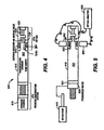
- FIG. 1 schematically represents a cross-section of earth 10 along the length of a wellbore penetration 11.
- the wellbore will be at least partially filled with a mixture of liquids including water, drilling fluid, and formation fluids that are indigenous to the earth formations penetrated by the wellbore.
- wellbore fluids such fluid mixtures are referred to as "wellbore fluids”.
- formation fluid hereinafter refers to a specific formation fluid exclusive of any substantial mixture or contamination by fluids not naturally present in the specific formation.
- a formation fluid sampling tool 20 Suspended within the wellbore 11 at the bottom end of a wire1 ine 12 is a formation fluid sampling tool 20.
- the wire1 ine 12 is often carried over a pulley 13 supported by a derrick 14.
- Wire1 ine deployment and retrieval is performed by a powered winch carried by a service truck 15, for example.
- FIG. 2 an exemplary embodiment of a sampling tool 20 is schematically illustrated by FIG. 2 .
- the sampling tools comprise a serial assembly of several tool segments that are joined end-to-end by the threaded sleeves of mutual compression unions 23.
- An assembly of tool segments appropriate for the present invention may include a hydraulic power unit 21 and a formation fluid extractor 22. Below the extractor 23, a large displacement volume motor/pump unit 24 is provided for line purging. Below the large volume pump is a similar motor/pump unit 25 having a smaller displacement volume that is quantitatively monitored as described more expansively with respect to FIG. 3 .
- one or more sample tank magazine sections 26 are assembled below the small volume pump. Each magazine section 26 may have three or more fluid sample tanks 30.
- the formation fluid extractor 22 comprises an extensible suction probe 27 that is opposed by bore wall feet 28. Both, the suction probe 27 and the opposing feet 28 are hydraulically extensible to firmly engage the wellbore walls. Construction and operational details of the fluid extraction tool 22 are more expansively described by U.S. Patent No. 5,303,775 , the specification of which is incorporated herewith.
- an advanced optical analyzer (AOA) 800 which comprises a sample tank 816 having an integral analytical top sub 818.
- the sample 821 in the sample tank can be pressurized by the pressurized compensation system which comprises a pressure compensation system 810, having a nitrogen pressure chamber 812.
- the nitrogen pressure is available when very high pressure is desired. Pressure is applied sufficient to keep a down hole fluid sample 821 in chamber 816 above the bubble point pressure and above the pressure at which asphaltenes precipitate out of the sample.
- the AOA is also suitable for downhole capture, pressurization and analysis of gas captured in a sample 821 confined in chamber 816.
- the present example of the AOA top sub 818 provides one or more optical conduits, which in this example are high-pressure sapphire windows 814 for ingress and egress of electromagnetic energy into the analysis chamber 800 optical analysis of parameters of interest for formation fluid sample 821.
- the entire AOA including the analysis chamber can be made of sapphire or another material which enables electromagnetic energy to pass through the material, thereby enabling visual inspection and noninvasive spectral and other analysis of the contents of the AOA, including the sample chamber.
- Optical conduits other than a sapphire window are acceptable.
- An analysis module 738 comprising a light source, light sensor and processor is provided which can be used for analysis of the sample 821 down hole or at the surface.
- Analysis module 738 is in contact with the sample 821 in sample region 823 for transmission and reception of NIR/MIR light into and through the sample in region 823.
- the light reflected, fluoresced and transmitted NIR/MIR light is analyzed for transmittance, reflectance and luminance by the processor in analysis module 738.
- a flexural mechanical resonator 840 connected to analysis module 738 by communication line 741 is also provided to determine fluid viscosity, density and other parameters of interest for the fluid sample using soft modeling techniques.
- the AOA 800 is removed from a sample tank carrier and the sample 821 pressure is stabilized by pumping pressurized water 920 behind the piston 921 using pump 910. At this time the nitrogen can be released and the nitrogen chamber can be detached from the sample chamber.
- An external optical analyzer 930 or analysis - module 738 comprising an NJR/MIR ultraviolet or visible light source and spectrometers provided for surfaces or down hole non-invasive analysis.
- the optical analyzer 930 is connected to a NIR/MIR light source 832 and a NIR/MIR light sensor 833 for analysis of light transmittance, fluorescence and total attenuated reflectance. That is, without disturbing the fluid sample or requiring transferring the sample to another Department of Transportation (DOT) approved chamber for transport to an off-site laboratory for analysis.
- DOT Department of Transportation
- the external optical analyzer 930 or internal analyzer 738 in the current example uses wavelength ranges from 1500 nm to 2000 nm to scan the fluid sample to determine or estimate through soft modeling techniques, parameters of interest, such as sample contamination percentage, gas oil ratio (GOR), density and asphaltene deposition pressure.
- a tunable diode laser and a Raman spectrometer are also provided in analysis module 738 for spectral analysis of the fluid sample.
- Each of the light sources and sensors are located inside of the sample tank 816 or communicate with the interior of the sample tank via the optical window 814 or an equivalent optical conduit providing data or electromagnetic energy ingress and egress to the interior of the sample tank and the sample retained therein.
- the analysis module 738 is attached as an integral part of the sample tank in the AOA prior to going down hole.
- the analysis module is used to perform NIR/MIR and other analysis described herein downhole during a run or at the surface upon completion of a sampling run downhole.
- An advantage for the disclosed method and apparatus is that no sample transfer is required, as non-invasive surface or down hole equipment in both the analysis module 738 and external equipment 830 perform PVT and spectral analysis to determine asphaltene deposition, bubble point, formation volume factor, compositional analysis and additional analysis described herein.
- FIG. 8 an alternative embodiment of the present invention is presented showing top sub 818 containing analysis module 738 attached to sample chamber 1210 pressurized by nitrogen (N 2 ) 1212 and hydrostatic pressure 1214 while down hole.
- N 2 nitrogen
- the present invention can perform sampling and sample analysis while down hole or at the surface as shown in FIG. 4, 5 and 8 .
- FIG. 9 an alternative embodiment is shown wherein an internal light source 830 and an internal sensor 833 are provided for noninvasive optical analysis of the sample 821.
- the internal processor embedded in analysis module 738, an external analyzer 930 or a surface analyzer in surface truck 15 process the optical data to determine a parameter of interest for the fluid sample 821.
- a ball 1301 is held in place by magnet 1317 and released in fluid sample contained in fluid sample chamber 1210.
- the ball is sensed by magnetic sensor 1319 upon arrival at point 1319.
- the processor determines the amount of time it takes for ball 1301 to travel between point 1317 and point 1319 and determines the fluid viscosity therefrom.
- analysis window unit comprises analysis module 738, tunable diode laser spectrometer 1415 or other optical spectrometer and sorption cooling unit 1416.
- Sorption cooling unit 1416 is described in co-owned patent application serial number 09/756,764 filed on January 8, 2001 entitled Downhole Sorption Cooling in Wireline Logging and Monitoring While Drilling" by Rocco DiFoggio, incorporated herein by reference in its entirety.
- the tunable diode laser 1415 spectrometer enable the ultra high resolution spectroscopy downhole or at the surface.
- Sorption cooling unit 1416 cools the tunable diode laser as necessary to obviate the adverse affects of downhole temperatures.
- FIG. 11 an alternative embodiment of the present invention is shown providing an external window unit 1510 for surface or downhole attachment of analysis equipment such as gas chromatographs or other analysis equipment.
- FIG. 12 is an illustration of an alternative embodiment having a single optical conduit 814, in this example a sapphire window 814 for ingress and egress of electromagnetic energy into and out of the sample chamber 816.
- Light from light source/sensor 832 enter the sample chamber 816 through single optical window 814. The light travels through the sample and bounces off of reflective surface 815.
- the round trip transmittance can determined from reflection and return of electromagnetic energy. Transmittance is determined for round trip travel of the light through the optical conduit, through the sample, reflected off of the reflective surface, returned through the sample and back through the optical conduit for measurement. Attenuated total reflectance and fluorescence response data are also sensed but do not use the reflective surface 815.
- the data is processed by processor in analysis module 738, internal analyzer/processor 930 or surface truck/controller/processor 15.
- the method and apparatus of the present invention is implemented as a set computer executable of instructions on a computer readable medium, comprising ROM, RAM, CD-ROM, Flash RAM or any other computer readable medium, now known or unknown that when executed cause a computer to implement the functions of the present invention.
Landscapes
- Life Sciences & Earth Sciences (AREA)
- Physics & Mathematics (AREA)
- Health & Medical Sciences (AREA)
- Chemical & Material Sciences (AREA)
- General Physics & Mathematics (AREA)
- Engineering & Computer Science (AREA)
- Immunology (AREA)
- Pathology (AREA)
- Analytical Chemistry (AREA)
- Biochemistry (AREA)
- General Health & Medical Sciences (AREA)
- Mining & Mineral Resources (AREA)
- Geology (AREA)
- Spectroscopy & Molecular Physics (AREA)
- General Life Sciences & Earth Sciences (AREA)
- Nuclear Medicine, Radiotherapy & Molecular Imaging (AREA)
- Fluid Mechanics (AREA)
- Oil, Petroleum & Natural Gas (AREA)
- Food Science & Technology (AREA)
- Medicinal Chemistry (AREA)
- Geophysics (AREA)
- Environmental & Geological Engineering (AREA)
- General Chemical & Material Sciences (AREA)
- Chemical Kinetics & Catalysis (AREA)
- Hydrology & Water Resources (AREA)
- Geochemistry & Mineralogy (AREA)
- Investigating, Analyzing Materials By Fluorescence Or Luminescence (AREA)
- Sampling And Sample Adjustment (AREA)
- Investigating Or Analysing Materials By Optical Means (AREA)
- Optical Measuring Cells (AREA)
Claims (18)
- Appareil pour estimer une propriété initiale d'un échantillon de fluide de formation, l'appareil comprenant :une enceinte d'analyse qui contient un échantillon de fluide de formation de fond de puits ;au moins un conduit optique formé dans l'enceinte d'analyse pour l'entrée et la sortie de l'énergie électromagnétique dans et de l'enceinte d'analyse contenant l'échantillon de formation de fluide, le au moins un conduit optique comprenant une première fenêtre optique formée dans l'enceinte d'analyse pour l'entrée de l'énergie électromagnétique depuis l'extérieur de l'enceinte d'analyse dans l'enceinte d'analyse et une deuxième fenêtre optique formée dans l'enceinte d'analyse pour la sortie de l'énergie électromagnétique de l'enceinte d'analyse ; etun système pour l'analyse de l'échantillon de fluide de formation se trouvant dans l'enceinte d'analyse, le système pour l'analyse de l'échantillon de fluide de formation comprenant un système de surface pour l'analyse de la sortie de l'énergie électromagnétique de l'enceinte d'analyse par la deuxième fenêtre optique pour estimer la propriété initiale de l'échantillon de fluide de formation à la surface.
- Appareil selon la revendication 1, dans lequel l'analyse comprend en outre l'analyse pour la transmittance, la fluorescence et la réflectance atténuée totale pour estimer la propriété initiale de l'échantillon de fluide de formation dans l'enceinte d'analyse.
- Appareil selon la revendication 1, dans lequel le système de surface comprend en outre une source de lumière proche infrarouge et un capteur de lumière proche infrarouge.
- Appareil selon la revendication 3, dans lequel le système de surface comprend en outre une source de lumière en infrarouge moyen et un capteur de lumière en infrarouge moyen.
- Appareil selon la revendication 1, dans lequel le système de surface comprend en outre un spectromètre.
- Appareil selon la revendication 1, dans lequel le système de surface comprend en outre une source de lumière visible et un capteur de lumière visible.
- Appareil selon la revendication 1, dans lequel la première fenêtre optique et la deuxième fenêtre optique sont des fenêtres saphir.
- Appareil selon la revendication 1, dans lequel le système de surface comprend en outre un spectromètre sélectionné dans le groupe consistant en un spectromètre de Raman, un spectromètre optique et un spectromètre d'absorption.
- Appareil selon la revendication 1, dans lequel l'enceinte d'analyse est réalisée entièrement en saphir.
- Appareil selon la revendication 1, dans lequel le conduit optique est une seule fenêtre, l'appareil comprenant en outre une surface de réflexion pour réfléchir l'énergie électromagnétique entrant dans la chambre d'analyse à travers l'unique fenêtre à nouveau à travers l'unique fenêtre.
- Appareil selon la revendication 1, l'appareil comprenant en outre :un résonateur piézoélectrique configuré pour estimer une deuxième propriété de l'échantillon de fluide de formation.
- Appareil selon la revendication 1, l'appareil comprenant en outre :un outil de fond de puits pour traverser un forage, où l'enceinte d'analyse se trouve dans l'outil de fond de puits pour contenir l'échantillon de fluide de formation, où l'enceinte d'analyse est montée amoviblement sur l'outil de fond de puits.
- Procédé pour estimer une propriété initiale d'un échantillon de fluide de formation, le procédé comprenant :capturer dans le fond de puits l'échantillon de fluide de formation dans une enceinte d'analyse ;introduire, à une surface, de l'énergie électromagnétique depuis l'extérieur de l'enceinte par une première fenêtre sur l'enceinte dans le fluide ; etanalyser, à la surface, l'échantillon de fluide de formation se trouvant dans l'enceinte d'analyse en analysant l'énergie électromagnétique sortant de l'enceinte d'analyse à travers une deuxième fenêtre optique pour estimer la propriété initiale de l'échantillon de fluide de formation se trouvant dans la chambre d'analyse.
- Procédé selon la revendication 13, dans lequel l'analyse comprend en outre l'analyse de la transmittance, de la fluorescence et de la réflectance atténuée totale pour estimer la propriété initiale de l'échantillon de fluide de formation dans l'enceinte d'analyse.
- Procédé selon la revendication 13, le procédé comprenant en outre :déterminer, à la surface, une deuxième propriété pour l'échantillon de fluide de formation en utilisant un résonateur piézoélectrique.
- Procédé selon la revendication 13, le procédé comprenant en outre :analyser l'énergie électromagnétique quittant l'enceinte d'analyse à travers un deuxième conduit optique.
- Procédé selon la revendication 13, le procédé comprenant en outre :traverser un forage avec un outil de fond contenant l'enceinte d'analyse.
- Procédé selon la revendication 16, le procédé comprenant en outre :retirer l'enceinte d'analyse de l'outil de fond à la surface.
Applications Claiming Priority (3)
| Application Number | Priority Date | Filing Date | Title |
|---|---|---|---|
| US46766803P | 2003-05-02 | 2003-05-02 | |
| EP07017683A EP1865147A1 (fr) | 2003-05-02 | 2004-04-29 | Procédé et appareil d'analyseur optique avancé |
| EP04750868A EP1631732B1 (fr) | 2003-05-02 | 2004-04-29 | Procede et appareil pour analyseur optique perfectionne |
Related Parent Applications (2)
| Application Number | Title | Priority Date | Filing Date |
|---|---|---|---|
| EP04750868.4 Division | 2004-04-29 | ||
| EP07017683.9 Division | 2007-09-10 |
Publications (2)
| Publication Number | Publication Date |
|---|---|
| EP2320026A1 EP2320026A1 (fr) | 2011-05-11 |
| EP2320026B1 true EP2320026B1 (fr) | 2013-04-24 |
Family
ID=33435101
Family Applications (3)
| Application Number | Title | Priority Date | Filing Date |
|---|---|---|---|
| EP10175791.2A Expired - Lifetime EP2320026B1 (fr) | 2003-05-02 | 2004-04-29 | Procede et appareil permettant d'obtenir un appareil de microechantillonnage |
| EP04750868A Expired - Lifetime EP1631732B1 (fr) | 2003-05-02 | 2004-04-29 | Procede et appareil pour analyseur optique perfectionne |
| EP04751109A Expired - Fee Related EP1623091B1 (fr) | 2003-05-02 | 2004-05-03 | Procede et appareil permettant d'obtenir un appareil de microechantillonnage |
Family Applications After (2)
| Application Number | Title | Priority Date | Filing Date |
|---|---|---|---|
| EP04750868A Expired - Lifetime EP1631732B1 (fr) | 2003-05-02 | 2004-04-29 | Procede et appareil pour analyseur optique perfectionne |
| EP04751109A Expired - Fee Related EP1623091B1 (fr) | 2003-05-02 | 2004-05-03 | Procede et appareil permettant d'obtenir un appareil de microechantillonnage |
Country Status (10)
| Country | Link |
|---|---|
| US (2) | US7210343B2 (fr) |
| EP (3) | EP2320026B1 (fr) |
| JP (1) | JP2007535655A (fr) |
| CN (1) | CN1784535B (fr) |
| BR (1) | BRPI0410046A (fr) |
| CA (1) | CA2524075A1 (fr) |
| DE (1) | DE602004012554T2 (fr) |
| NO (1) | NO20055319L (fr) |
| RU (1) | RU2333357C2 (fr) |
| WO (2) | WO2004099566A1 (fr) |
Families Citing this family (122)
| Publication number | Priority date | Publication date | Assignee | Title |
|---|---|---|---|---|
| BRPI0409842B1 (pt) * | 2003-05-02 | 2015-03-03 | Baker Hughes Inc | Aparelho e método para registrar o histórico de um parâmetro de interesse de uma amostra de fluido de formação de fundo de poço |
| US7196786B2 (en) * | 2003-05-06 | 2007-03-27 | Baker Hughes Incorporated | Method and apparatus for a tunable diode laser spectrometer for analysis of hydrocarbon samples |
| US7782460B2 (en) * | 2003-05-06 | 2010-08-24 | Baker Hughes Incorporated | Laser diode array downhole spectrometer |
| US20070081157A1 (en) * | 2003-05-06 | 2007-04-12 | Baker Hughes Incorporated | Apparatus and method for estimating filtrate contamination in a formation fluid |
| US7408645B2 (en) * | 2003-11-10 | 2008-08-05 | Baker Hughes Incorporated | Method and apparatus for a downhole spectrometer based on tunable optical filters |
| US7490664B2 (en) * | 2004-11-12 | 2009-02-17 | Halliburton Energy Services, Inc. | Drilling, perforating and formation analysis |
| US7565835B2 (en) | 2004-11-17 | 2009-07-28 | Schlumberger Technology Corporation | Method and apparatus for balanced pressure sampling |
| US7546885B2 (en) * | 2005-05-19 | 2009-06-16 | Schlumberger Technology Corporation | Apparatus and method for obtaining downhole samples |
| EP1736756A1 (fr) * | 2005-06-20 | 2006-12-27 | Bp Oil International Limited | Développement des pointes jetable et fermable hermétiquement pour de sondes NIR-spectroscopique. |
| US7475593B2 (en) | 2005-06-24 | 2009-01-13 | Precision Energy Services, Inc. | High temperature near infrared for measurements and telemetry in well boreholes |
| US7472589B2 (en) | 2005-11-07 | 2009-01-06 | Halliburton Energy Services, Inc. | Single phase fluid sampling apparatus and method for use of same |
| US7596995B2 (en) | 2005-11-07 | 2009-10-06 | Halliburton Energy Services, Inc. | Single phase fluid sampling apparatus and method for use of same |
| US8429961B2 (en) | 2005-11-07 | 2013-04-30 | Halliburton Energy Services, Inc. | Wireline conveyed single phase fluid sampling apparatus and method for use of same |
| US7874206B2 (en) | 2005-11-07 | 2011-01-25 | Halliburton Energy Services, Inc. | Single phase fluid sampling apparatus and method for use of same |
| US7428925B2 (en) * | 2005-11-21 | 2008-09-30 | Schlumberger Technology Corporation | Wellbore formation evaluation system and method |
| US7681450B2 (en) * | 2005-12-09 | 2010-03-23 | Baker Hughes Incorporated | Casing resonant radial flexural modes in cement bond evaluation |
| US7458257B2 (en) * | 2005-12-19 | 2008-12-02 | Schlumberger Technology Corporation | Downhole measurement of formation characteristics while drilling |
| US20080087470A1 (en) | 2005-12-19 | 2008-04-17 | Schlumberger Technology Corporation | Formation Evaluation While Drilling |
| US7367394B2 (en) | 2005-12-19 | 2008-05-06 | Schlumberger Technology Corporation | Formation evaluation while drilling |
| US20080111064A1 (en) * | 2006-11-10 | 2008-05-15 | Schlumberger Technology Corporation | Downhole measurement of substances in earth formations |
| US7482811B2 (en) * | 2006-11-10 | 2009-01-27 | Schlumberger Technology Corporation | Magneto-optical method and apparatus for determining properties of reservoir fluids |
| US7586087B2 (en) * | 2007-01-24 | 2009-09-08 | Schlumberger Technology Corporation | Methods and apparatus to characterize stock-tank oil during fluid composition analysis |
| US20090066959A1 (en) * | 2007-09-07 | 2009-03-12 | Baker Hughes Incorporated | Apparatus and Method for Estimating a Property of a Fluid in a Wellbore Using Photonic Crystals |
| US8028562B2 (en) * | 2007-12-17 | 2011-10-04 | Schlumberger Technology Corporation | High pressure and high temperature chromatography |
| US8794350B2 (en) * | 2007-12-19 | 2014-08-05 | Bp Corporation North America Inc. | Method for detecting formation pore pressure by detecting pumps-off gas downhole |
| US20090159334A1 (en) * | 2007-12-19 | 2009-06-25 | Bp Corporation North America, Inc. | Method for detecting formation pore pressure by detecting pumps-off gas downhole |
| US8297351B2 (en) * | 2007-12-27 | 2012-10-30 | Schlumberger Technology Corporation | Downhole sensing system using carbon nanotube FET |
| US7886821B2 (en) * | 2008-01-24 | 2011-02-15 | Baker Hughes Incorporated | Apparatus and method for determining fluid properties |
| US8032311B2 (en) | 2008-05-22 | 2011-10-04 | Baker Hughes Incorporated | Estimating gas-oil ratio from other physical properties |
| US9074422B2 (en) | 2011-02-24 | 2015-07-07 | Foro Energy, Inc. | Electric motor for laser-mechanical drilling |
| US9347271B2 (en) | 2008-10-17 | 2016-05-24 | Foro Energy, Inc. | Optical fiber cable for transmission of high power laser energy over great distances |
| US8571368B2 (en) | 2010-07-21 | 2013-10-29 | Foro Energy, Inc. | Optical fiber configurations for transmission of laser energy over great distances |
| US9080425B2 (en) | 2008-10-17 | 2015-07-14 | Foro Energy, Inc. | High power laser photo-conversion assemblies, apparatuses and methods of use |
| US9360631B2 (en) | 2008-08-20 | 2016-06-07 | Foro Energy, Inc. | Optics assembly for high power laser tools |
| US9664012B2 (en) | 2008-08-20 | 2017-05-30 | Foro Energy, Inc. | High power laser decomissioning of multistring and damaged wells |
| US9138786B2 (en) | 2008-10-17 | 2015-09-22 | Foro Energy, Inc. | High power laser pipeline tool and methods of use |
| US20120261188A1 (en) | 2008-08-20 | 2012-10-18 | Zediker Mark S | Method of high power laser-mechanical drilling |
| US9669492B2 (en) | 2008-08-20 | 2017-06-06 | Foro Energy, Inc. | High power laser offshore decommissioning tool, system and methods of use |
| US8627901B1 (en) | 2009-10-01 | 2014-01-14 | Foro Energy, Inc. | Laser bottom hole assembly |
| US9027668B2 (en) | 2008-08-20 | 2015-05-12 | Foro Energy, Inc. | Control system for high power laser drilling workover and completion unit |
| US9244235B2 (en) | 2008-10-17 | 2016-01-26 | Foro Energy, Inc. | Systems and assemblies for transferring high power laser energy through a rotating junction |
| US9242309B2 (en) | 2012-03-01 | 2016-01-26 | Foro Energy Inc. | Total internal reflection laser tools and methods |
| US8424617B2 (en) | 2008-08-20 | 2013-04-23 | Foro Energy Inc. | Methods and apparatus for delivering high power laser energy to a surface |
| US9719302B2 (en) | 2008-08-20 | 2017-08-01 | Foro Energy, Inc. | High power laser perforating and laser fracturing tools and methods of use |
| US9267330B2 (en) | 2008-08-20 | 2016-02-23 | Foro Energy, Inc. | Long distance high power optical laser fiber break detection and continuity monitoring systems and methods |
| US10301912B2 (en) * | 2008-08-20 | 2019-05-28 | Foro Energy, Inc. | High power laser flow assurance systems, tools and methods |
| US9089928B2 (en) | 2008-08-20 | 2015-07-28 | Foro Energy, Inc. | Laser systems and methods for the removal of structures |
| US8379207B2 (en) * | 2008-10-15 | 2013-02-19 | Baker Hughes Incorporated | Method and apparatus for estimating a fluid property |
| US7967067B2 (en) | 2008-11-13 | 2011-06-28 | Halliburton Energy Services, Inc. | Coiled tubing deployed single phase fluid sampling apparatus |
| EP2816193A3 (fr) | 2009-06-29 | 2015-04-15 | Halliburton Energy Services, Inc. | Opérations de laser de puits de forage |
| US20110016962A1 (en) * | 2009-07-21 | 2011-01-27 | Baker Hughes Incorporated | Detector for Characterizing a Fluid |
| US8720584B2 (en) | 2011-02-24 | 2014-05-13 | Foro Energy, Inc. | Laser assisted system for controlling deep water drilling emergency situations |
| US8684088B2 (en) | 2011-02-24 | 2014-04-01 | Foro Energy, Inc. | Shear laser module and method of retrofitting and use |
| US8783361B2 (en) | 2011-02-24 | 2014-07-22 | Foro Energy, Inc. | Laser assisted blowout preventer and methods of use |
| US8783360B2 (en) | 2011-02-24 | 2014-07-22 | Foro Energy, Inc. | Laser assisted riser disconnect and method of use |
| US9091151B2 (en) | 2009-11-19 | 2015-07-28 | Halliburton Energy Services, Inc. | Downhole optical radiometry tool |
| US8839871B2 (en) | 2010-01-15 | 2014-09-23 | Halliburton Energy Services, Inc. | Well tools operable via thermal expansion resulting from reactive materials |
| US8306762B2 (en) * | 2010-01-25 | 2012-11-06 | Baker Hughes Incorporated | Systems and methods for analysis of downhole data |
| US8508741B2 (en) * | 2010-04-12 | 2013-08-13 | Baker Hughes Incorporated | Fluid sampling and analysis downhole using microconduit system |
| US9297255B2 (en) * | 2010-06-17 | 2016-03-29 | Halliburton Energy Services, Inc. | Non-invasive compressibility and in situ density testing of a fluid sample in a sealed chamber |
| SG186951A1 (en) | 2010-07-08 | 2013-02-28 | Halliburton Energy Serv Inc | Method and system of determining constituent components of a fluid sample |
| WO2012024285A1 (fr) | 2010-08-17 | 2012-02-23 | Foro Energy Inc. | Systèmes et structures d'acheminement destinés à une émission laser longue distance à haute puissance |
| US9429014B2 (en) | 2010-09-29 | 2016-08-30 | Schlumberger Technology Corporation | Formation fluid sample container apparatus |
| US20120086454A1 (en) * | 2010-10-07 | 2012-04-12 | Baker Hughes Incorporated | Sampling system based on microconduit lab on chip |
| US8474533B2 (en) * | 2010-12-07 | 2013-07-02 | Halliburton Energy Services, Inc. | Gas generator for pressurizing downhole samples |
| US20120145907A1 (en) * | 2010-12-14 | 2012-06-14 | Van Groos August F Koster | Dynamic environmental chamber and methods of radiation analysis |
| AU2010365401B2 (en) | 2010-12-17 | 2015-04-09 | Halliburton Energy Services, Inc. | Well perforating with determination of well characteristics |
| US8397800B2 (en) | 2010-12-17 | 2013-03-19 | Halliburton Energy Services, Inc. | Perforating string with longitudinal shock de-coupler |
| US8393393B2 (en) | 2010-12-17 | 2013-03-12 | Halliburton Energy Services, Inc. | Coupler compliance tuning for mitigating shock produced by well perforating |
| US8985200B2 (en) | 2010-12-17 | 2015-03-24 | Halliburton Energy Services, Inc. | Sensing shock during well perforating |
| US8397814B2 (en) | 2010-12-17 | 2013-03-19 | Halliburton Energy Serivces, Inc. | Perforating string with bending shock de-coupler |
| US20120241169A1 (en) | 2011-03-22 | 2012-09-27 | Halliburton Energy Services, Inc. | Well tool assemblies with quick connectors and shock mitigating capabilities |
| FR2973828B1 (fr) * | 2011-04-11 | 2014-04-18 | Snf Sas | Ensemble de materiel de mesure et regulation de viscosite en ligne a haute pression |
| WO2012167102A1 (fr) | 2011-06-03 | 2012-12-06 | Foro Energy Inc. | Connecteurs optiques robustes à fibre laser d'énergie élevée passivement refroidie et procédés d'utilisation |
| US9091152B2 (en) | 2011-08-31 | 2015-07-28 | Halliburton Energy Services, Inc. | Perforating gun with internal shock mitigation |
| DE102011086206A1 (de) | 2011-11-11 | 2013-05-16 | Carl Zeiss Ag | Anordnung zum Bestimmen der optischen Eigenschaften von Bohrlochfluiden |
| US8547556B2 (en) * | 2011-12-14 | 2013-10-01 | Halliburton Energy Services, Inc. | Methods of analyzing a reservoir fluid sample using a multivariate optical element calculation device |
| SG11201402053WA (en) * | 2011-12-14 | 2014-09-26 | Halliburton Energy Services Inc | Methods of analyzing a reservoir fluid sample using a multivariate optical element calculation device |
| US9057256B2 (en) * | 2012-01-10 | 2015-06-16 | Schlumberger Technology Corporation | Submersible pump control |
| DE102012100794B3 (de) * | 2012-01-31 | 2013-02-28 | Airbus Operations Gmbh | Vorrichtung und Verfahren zum Erfassen von Kontaminationen in einem Hydrauliksystem |
| US20130213648A1 (en) * | 2012-02-16 | 2013-08-22 | Baker Hughes Incorporated | Optical fluid analyzer sampling tool using open beam optical construction |
| BR112015004458A8 (pt) | 2012-09-01 | 2019-08-27 | Chevron Usa Inc | sistema de controle de poço, bop a laser e conjunto de bop |
| US9169705B2 (en) | 2012-10-25 | 2015-10-27 | Halliburton Energy Services, Inc. | Pressure relief-assisted packer |
| US9249656B2 (en) * | 2012-11-15 | 2016-02-02 | Baker Hughes Incorporated | High precision locked laser operating at elevated temperatures |
| US9187999B2 (en) * | 2012-11-30 | 2015-11-17 | Baker Hughes Incorporated | Apparatus and method for obtaining formation fluid samples |
| US9534494B2 (en) | 2013-02-25 | 2017-01-03 | Schlumberger Technology Corporation | Optical window assemblies |
| US9429013B2 (en) | 2013-02-25 | 2016-08-30 | Schlumberger Technology Corporation | Optical window assembly for an optical sensor of a downhole tool and method of using same |
| US9587486B2 (en) | 2013-02-28 | 2017-03-07 | Halliburton Energy Services, Inc. | Method and apparatus for magnetic pulse signature actuation |
| WO2014137322A1 (fr) | 2013-03-05 | 2014-09-12 | Halliburton Energy Services Inc. | Système, procédé et produit-programme d'ordinateur pour conception de système photométrique et renforcement environnemental |
| US9982530B2 (en) | 2013-03-12 | 2018-05-29 | Halliburton Energy Services, Inc. | Wellbore servicing tools, systems and methods utilizing near-field communication |
| US20140268156A1 (en) * | 2013-03-13 | 2014-09-18 | Schlumberger Technology Corporation | Method and system for determining bubble point pressure |
| US9284817B2 (en) | 2013-03-14 | 2016-03-15 | Halliburton Energy Services, Inc. | Dual magnetic sensor actuation assembly |
| US9752414B2 (en) | 2013-05-31 | 2017-09-05 | Halliburton Energy Services, Inc. | Wellbore servicing tools, systems and methods utilizing downhole wireless switches |
| US20150075770A1 (en) | 2013-05-31 | 2015-03-19 | Michael Linley Fripp | Wireless activation of wellbore tools |
| US9109434B2 (en) | 2013-06-09 | 2015-08-18 | Schlumberger Technology Corporation | System and method for estimating oil formation volume factor downhole |
| WO2015047247A1 (fr) | 2013-09-25 | 2015-04-02 | Halliburton Energy Services, Inc. | Systèmes et procédés de mesure en temps réel d'un contenu gazeux dans des fluides de forage |
| US10415380B2 (en) * | 2013-10-01 | 2019-09-17 | Baker Hughes, A Ge Company, Llc | Sample tank with integrated fluid separation |
| GB2534797B (en) | 2013-11-13 | 2017-03-01 | Schlumberger Holdings | Automatic pumping system commissioning |
| EP3090245A1 (fr) | 2014-03-07 | 2016-11-09 | Halliburton Energy Services, Inc. | Procédés et systèmes d'échantillonnage de fluide de formation |
| NO342929B1 (no) * | 2014-04-16 | 2018-09-03 | Vision Io As | Inspeksjonsverktøy |
| GB2543973B (en) | 2014-08-26 | 2021-01-20 | Halliburton Energy Services Inc | Systems and methods for in situ monitoring of cement slurry locations and setting processes thereof |
| WO2016085465A1 (fr) | 2014-11-25 | 2016-06-02 | Halliburton Energy Services, Inc. | Activation sans fil d'outils de puits de forage |
| WO2016129177A1 (fr) * | 2015-02-10 | 2016-08-18 | ソニー株式会社 | Dispositif de réception et système de communication |
| CN105300902A (zh) * | 2015-10-26 | 2016-02-03 | 北京农业信息技术研究中心 | 五点法差异深度药剂蒸发高通量信息动态获取方法 |
| US10221687B2 (en) | 2015-11-26 | 2019-03-05 | Merger Mines Corporation | Method of mining using a laser |
| WO2018071036A1 (fr) * | 2016-10-14 | 2018-04-19 | Halliburton Energy Services, Inc. | Traitement in situ de capteurs chimiques |
| CN107907503B (zh) * | 2017-01-17 | 2020-06-05 | 合肥中科富华新材料有限公司 | 多腔室的激光检测监测仪 |
| US10371633B2 (en) | 2017-10-30 | 2019-08-06 | Saudi Arabian Oil Company | Determining a specific gravity of a sample |
| WO2019236105A1 (fr) * | 2018-06-08 | 2019-12-12 | Halliburton Energy Services, Inc. | Appareil, système et procédé de test mécanique dans des conditions de confinement |
| US11479373B2 (en) * | 2018-08-14 | 2022-10-25 | Honeybee Robotics, Llc | Sample collection system for interplanetary vehicle |
| US11262298B2 (en) | 2018-08-30 | 2022-03-01 | Caterpillar Inc. | System and method for determining fluid origin |
| US11275022B2 (en) | 2018-09-05 | 2022-03-15 | Halliburton Energy Services, Inc. | Two frequency comb fourier spectroscopy for chemical sensing |
| WO2020112106A1 (fr) | 2018-11-28 | 2020-06-04 | Halliburton Energy Services, Inc. | Extracteurs d'échantillons de fond de trou et systèmes d'extraction d'échantillons de fond de trou |
| CN109667579B (zh) * | 2018-12-28 | 2021-07-13 | 中国科学院武汉岩土力学研究所 | 一种超低渗地层内深井气液流体取样装置 |
| US11408282B2 (en) * | 2019-05-10 | 2022-08-09 | Baker Hughes Oilfield Operations Llc | Bi-conical optical sensor for obtaining downhole fluid properties |
| CN110672550B (zh) * | 2019-09-10 | 2021-11-19 | 中国科学院上海技术物理研究所 | 一种微区重要生物资源像谱分析仪 |
| DE102019135595A1 (de) * | 2019-12-20 | 2021-06-24 | Endress+Hauser Conducta Gmbh+Co. Kg | Wechselarmatur für Eintauch-, Durchfluss- und Anbau-Messsysteme in der analytischen Prozesstechnik |
| CN113049522B (zh) * | 2019-12-26 | 2023-07-25 | 中国石油天然气股份有限公司 | 能够消除气泡的近红外分析装置 |
| US11624722B2 (en) | 2020-04-24 | 2023-04-11 | The Boeing Company | Method and systems for determining dielectric breakdown voltages of fluid samples using dielectric fluid testers |
| CN111781019A (zh) * | 2020-07-03 | 2020-10-16 | 中国海洋石油集团有限公司 | 一种泵抽模块和流体取样方法 |
| US11662288B2 (en) | 2020-09-24 | 2023-05-30 | Saudi Arabian Oil Company | Method for measuring API gravity of petroleum crude oils using angle-resolved fluorescence spectra |
| CN113899727B (zh) * | 2021-09-18 | 2022-11-18 | 中山大学 | 检测沉积物孔隙水中目标物浓度垂向变化的设备及方法 |
Family Cites Families (51)
| Publication number | Priority date | Publication date | Assignee | Title |
|---|---|---|---|---|
| US3448611A (en) * | 1966-09-29 | 1969-06-10 | Schlumberger Technology Corp | Method and apparatus for formation testing |
| US3611799A (en) * | 1969-10-01 | 1971-10-12 | Dresser Ind | Multiple chamber earth formation fluid sampler |
| US3608715A (en) * | 1970-02-06 | 1971-09-28 | Brockway Glass Co Inc | Method and apparatus for inspecting liquids |
| US3780575A (en) * | 1972-12-08 | 1973-12-25 | Schlumberger Technology Corp | Formation-testing tool for obtaining multiple measurements and fluid samples |
| US3859851A (en) * | 1973-12-12 | 1975-01-14 | Schlumberger Technology Corp | Methods and apparatus for testing earth formations |
| JPS55910Y2 (fr) * | 1975-03-28 | 1980-01-11 | ||
| FR2558522B1 (fr) | 1983-12-22 | 1986-05-02 | Schlumberger Prospection | Dispositif pour prelever un echantillon representatif du fluide present dans un puits, et procede correspondant |
| US4721157A (en) | 1986-05-12 | 1988-01-26 | Baker Oil Tools, Inc. | Fluid sampling apparatus |
| US4766955A (en) | 1987-04-10 | 1988-08-30 | Atlantic Richfield Company | Wellbore fluid sampling apparatus |
| US4787447A (en) * | 1987-06-19 | 1988-11-29 | Halliburton Company | Well fluid modular sampling apparatus |
| US4994671A (en) * | 1987-12-23 | 1991-02-19 | Schlumberger Technology Corporation | Apparatus and method for analyzing the composition of formation fluids |
| US4936139A (en) * | 1988-09-23 | 1990-06-26 | Schlumberger Technology Corporation | Down hole method for determination of formation properties |
| CA1325379C (fr) | 1988-11-17 | 1993-12-21 | Owen T. Krauss | Dispositif d'echantillonnnage en fond de puits |
| US4903765A (en) | 1989-01-06 | 1990-02-27 | Halliburton Company | Delayed opening fluid sampler |
| GB9003467D0 (en) | 1990-02-15 | 1990-04-11 | Oilphase Sampling Services Ltd | Sampling tool |
| US5166747A (en) * | 1990-06-01 | 1992-11-24 | Schlumberger Technology Corporation | Apparatus and method for analyzing the composition of formation fluids |
| US5077481A (en) * | 1990-10-25 | 1991-12-31 | The Perkin-Elmer Corporation | Optical probe for measuring light transmission of liquid |
| US5178178A (en) * | 1991-01-07 | 1993-01-12 | Hewlett-Packard Company | Valve assembly |
| NO172863C (no) | 1991-05-03 | 1993-09-15 | Norsk Hydro As | Elektro-hydraulisk bunnhullsproevetakerutstyr |
| US5240072A (en) | 1991-09-24 | 1993-08-31 | Halliburton Company | Multiple sample annulus pressure responsive sampler |
| US5377755A (en) | 1992-11-16 | 1995-01-03 | Western Atlas International, Inc. | Method and apparatus for acquiring and processing subsurface samples of connate fluid |
| US5303775A (en) | 1992-11-16 | 1994-04-19 | Western Atlas International, Inc. | Method and apparatus for acquiring and processing subsurface samples of connate fluid |
| US5329811A (en) | 1993-02-04 | 1994-07-19 | Halliburton Company | Downhole fluid property measurement tool |
| US5361839A (en) | 1993-03-24 | 1994-11-08 | Schlumberger Technology Corporation | Full bore sampler including inlet and outlet ports flanking an annular sample chamber and parameter sensor and memory apparatus disposed in said sample chamber |
| US5662166A (en) | 1995-10-23 | 1997-09-02 | Shammai; Houman M. | Apparatus for maintaining at least bottom hole pressure of a fluid sample upon retrieval from an earth bore |
| US5734098A (en) * | 1996-03-25 | 1998-03-31 | Nalco/Exxon Energy Chemicals, L.P. | Method to monitor and control chemical treatment of petroleum, petrochemical and processes with on-line quartz crystal microbalance sensors |
| US5741962A (en) * | 1996-04-05 | 1998-04-21 | Halliburton Energy Services, Inc. | Apparatus and method for analyzing a retrieving formation fluid utilizing acoustic measurements |
| US5902939A (en) * | 1996-06-04 | 1999-05-11 | U.S. Army Corps Of Engineers As Represented By The Secretary Of The Army | Penetrometer sampler system for subsurface spectral analysis of contaminated media |
| US5934374A (en) * | 1996-08-01 | 1999-08-10 | Halliburton Energy Services, Inc. | Formation tester with improved sample collection system |
| US5859430A (en) * | 1997-04-10 | 1999-01-12 | Schlumberger Technology Corporation | Method and apparatus for the downhole compositional analysis of formation gases |
| US6092416A (en) * | 1997-04-16 | 2000-07-25 | Schlumberger Technology Corporation | Downholed system and method for determining formation properties |
| US5939717A (en) * | 1998-01-29 | 1999-08-17 | Schlumberger Technology Corporation | Methods and apparatus for determining gas-oil ratio in a geological formation through the use of spectroscopy |
| US6218662B1 (en) * | 1998-04-23 | 2001-04-17 | Western Atlas International, Inc. | Downhole carbon dioxide gas analyzer |
| US6178815B1 (en) * | 1998-07-30 | 2001-01-30 | Schlumberger Technology Corporation | Method to improve the quality of a formation fluid sample |
| JP3479227B2 (ja) * | 1998-12-07 | 2003-12-15 | 国際航業株式会社 | 地中汚染物質の測定方法及び装置 |
| US6350986B1 (en) * | 1999-02-23 | 2002-02-26 | Schlumberger Technology Corporation | Analysis of downhole OBM-contaminated formation fluid |
| US6688390B2 (en) * | 1999-03-25 | 2004-02-10 | Schlumberger Technology Corporation | Formation fluid sampling apparatus and method |
| US6378364B1 (en) * | 2000-01-13 | 2002-04-30 | Halliburton Energy Services, Inc. | Downhole densitometer |
| US6437326B1 (en) * | 2000-06-27 | 2002-08-20 | Schlumberger Technology Corporation | Permanent optical sensor downhole fluid analysis systems |
| US6474152B1 (en) * | 2000-11-02 | 2002-11-05 | Schlumberger Technology Corporation | Methods and apparatus for optically measuring fluid compressibility downhole |
| US6467544B1 (en) | 2000-11-14 | 2002-10-22 | Schlumberger Technology Corporation | Sample chamber with dead volume flushing |
| US6557632B2 (en) * | 2001-03-15 | 2003-05-06 | Baker Hughes Incorporated | Method and apparatus to provide miniature formation fluid sample |
| JP4188087B2 (ja) * | 2001-03-23 | 2008-11-26 | シュルンベルジェ ホールディングス リミテッド | 流体特性センサー |
| EP1397661B1 (fr) * | 2001-05-15 | 2008-09-10 | Baker Hughes Incorporated | Procede et appareil de caracterisation de fluides de fond impliquant la mise en oeuvre de resonateurs mecaniques de flexion |
| GB2377952B (en) * | 2001-07-27 | 2004-01-28 | Schlumberger Holdings | Receptacle for sampling downhole |
| US7246664B2 (en) * | 2001-09-19 | 2007-07-24 | Baker Hughes Incorporated | Dual piston, single phase sampling mechanism and procedure |
| US6683681B2 (en) * | 2002-04-10 | 2004-01-27 | Baker Hughes Incorporated | Method and apparatus for a downhole refractometer and attenuated reflectance spectrometer |
| US6640625B1 (en) * | 2002-05-08 | 2003-11-04 | Anthony R. H. Goodwin | Method and apparatus for measuring fluid density downhole |
| US6907797B2 (en) * | 2002-11-12 | 2005-06-21 | Baker Hughes Incorporated | Method and apparatus for supercharging downhole sample tanks |
| US7081615B2 (en) * | 2002-12-03 | 2006-07-25 | Schlumberger Technology Corporation | Methods and apparatus for the downhole characterization of formation fluids |
| BRPI0409842B1 (pt) * | 2003-05-02 | 2015-03-03 | Baker Hughes Inc | Aparelho e método para registrar o histórico de um parâmetro de interesse de uma amostra de fluido de formação de fundo de poço |
-
2004
- 2004-04-29 EP EP10175791.2A patent/EP2320026B1/fr not_active Expired - Lifetime
- 2004-04-29 CA CA002524075A patent/CA2524075A1/fr not_active Abandoned
- 2004-04-29 JP JP2006513414A patent/JP2007535655A/ja active Pending
- 2004-04-29 EP EP04750868A patent/EP1631732B1/fr not_active Expired - Lifetime
- 2004-04-29 DE DE602004012554T patent/DE602004012554T2/de not_active Expired - Lifetime
- 2004-04-29 WO PCT/US2004/013165 patent/WO2004099566A1/fr active Search and Examination
- 2004-04-30 US US10/836,996 patent/US7210343B2/en not_active Expired - Fee Related
- 2004-04-30 US US10/837,475 patent/US7671983B2/en active Active
- 2004-05-03 RU RU2005137357/03A patent/RU2333357C2/ru not_active IP Right Cessation
- 2004-05-03 BR BRPI0410046-8A patent/BRPI0410046A/pt not_active Application Discontinuation
- 2004-05-03 WO PCT/US2004/013552 patent/WO2004099564A2/fr active Application Filing
- 2004-05-03 CN CN2004800118652A patent/CN1784535B/zh not_active Expired - Fee Related
- 2004-05-03 EP EP04751109A patent/EP1623091B1/fr not_active Expired - Fee Related
-
2005
- 2005-11-11 NO NO20055319A patent/NO20055319L/no not_active Application Discontinuation
Also Published As
| Publication number | Publication date |
|---|---|
| WO2004099566A1 (fr) | 2004-11-18 |
| CA2524075A1 (fr) | 2004-11-18 |
| US7671983B2 (en) | 2010-03-02 |
| CN1784535A (zh) | 2006-06-07 |
| DE602004012554T2 (de) | 2009-04-16 |
| NO20055319L (no) | 2005-11-11 |
| DE602004012554D1 (de) | 2008-04-30 |
| RU2005137357A (ru) | 2007-06-10 |
| CN1784535B (zh) | 2010-09-29 |
| BRPI0410046A (pt) | 2006-04-25 |
| JP2007535655A (ja) | 2007-12-06 |
| US7210343B2 (en) | 2007-05-01 |
| EP1623091A2 (fr) | 2006-02-08 |
| US20040218176A1 (en) | 2004-11-04 |
| EP1631732A1 (fr) | 2006-03-08 |
| US20040244971A1 (en) | 2004-12-09 |
| WO2004099564A3 (fr) | 2005-02-10 |
| EP2320026A1 (fr) | 2011-05-11 |
| EP1623091B1 (fr) | 2009-04-01 |
| RU2333357C2 (ru) | 2008-09-10 |
| WO2004099564A2 (fr) | 2004-11-18 |
| EP1631732B1 (fr) | 2008-03-19 |
Similar Documents
| Publication | Publication Date | Title |
|---|---|---|
| EP2320026B1 (fr) | Procede et appareil permettant d'obtenir un appareil de microechantillonnage | |
| US8023690B2 (en) | Apparatus and method for imaging fluids downhole | |
| CA2605830C (fr) | Procedes et appareil d'analyse de fluide de fond | |
| CA2639577C (fr) | Procede pour mesurer la pression du point de bulle d'un fluide de fond de trou | |
| US8434357B2 (en) | Clean fluid sample for downhole measurements | |
| EP1620631B1 (fr) | Enregistreur de donnees continu pour reservoir d'echantillons de fond | |
| WO2000042416A1 (fr) | Instrument optique et procede d'analyse des fluides d'une formation | |
| US20090059332A1 (en) | System and method for dual path length optical analysis of fluids downhole | |
| US7852468B2 (en) | Fiber optic refractometer | |
| US7886821B2 (en) | Apparatus and method for determining fluid properties | |
| EP1865147A1 (fr) | Procédé et appareil d'analyseur optique avancé | |
| GB2391939A (en) | Method of analysing a formation fluid from a formation surrounding a wellbore having a borehole fluid | |
| US10316650B2 (en) | Gas phase detection of downhole fluid sample components | |
| US20090066959A1 (en) | Apparatus and Method for Estimating a Property of a Fluid in a Wellbore Using Photonic Crystals |
Legal Events
| Date | Code | Title | Description |
|---|---|---|---|
| PUAI | Public reference made under article 153(3) epc to a published international application that has entered the european phase |
Free format text: ORIGINAL CODE: 0009012 |
|
| 17P | Request for examination filed |
Effective date: 20100908 |
|
| AC | Divisional application: reference to earlier application |
Ref document number: 1631732 Country of ref document: EP Kind code of ref document: P Ref document number: 1865147 Country of ref document: EP Kind code of ref document: P |
|
| AK | Designated contracting states |
Kind code of ref document: A1 Designated state(s): DE FR GB |
|
| RIN1 | Information on inventor provided before grant (corrected) |
Inventor name: GORDAN, ROBERT Inventor name: SHAMMAI, HOUMAN M Inventor name: DIFOGGIO, ROCCO |
|
| RIC1 | Information provided on ipc code assigned before grant |
Ipc: E21B 49/08 20060101AFI20121005BHEP |
|
| GRAP | Despatch of communication of intention to grant a patent |
Free format text: ORIGINAL CODE: EPIDOSNIGR1 |
|
| GRAS | Grant fee paid |
Free format text: ORIGINAL CODE: EPIDOSNIGR3 |
|
| GRAA | (expected) grant |
Free format text: ORIGINAL CODE: 0009210 |
|
| AC | Divisional application: reference to earlier application |
Ref document number: 1865147 Country of ref document: EP Kind code of ref document: P Ref document number: 1631732 Country of ref document: EP Kind code of ref document: P |
|
| AK | Designated contracting states |
Kind code of ref document: B1 Designated state(s): DE FR GB |
|
| REG | Reference to a national code |
Ref country code: GB Ref legal event code: FG4D |
|
| REG | Reference to a national code |
Ref country code: DE Ref legal event code: R096 Ref document number: 602004041923 Country of ref document: DE Effective date: 20130627 |
|
| PG25 | Lapsed in a contracting state [announced via postgrant information from national office to epo] |
Ref country code: DE Free format text: LAPSE BECAUSE OF NON-PAYMENT OF DUE FEES Effective date: 20131101 |
|
| REG | Reference to a national code |
Ref country code: DE Ref legal event code: R119 Ref document number: 602004041923 Country of ref document: DE Effective date: 20131101 |
|
| PLBE | No opposition filed within time limit |
Free format text: ORIGINAL CODE: 0009261 |
|
| STAA | Information on the status of an ep patent application or granted ep patent |
Free format text: STATUS: NO OPPOSITION FILED WITHIN TIME LIMIT |
|
| 26N | No opposition filed |
Effective date: 20140127 |
|
| REG | Reference to a national code |
Ref country code: FR Ref legal event code: ST Effective date: 20140303 |
|
| PG25 | Lapsed in a contracting state [announced via postgrant information from national office to epo] |
Ref country code: FR Free format text: LAPSE BECAUSE OF NON-PAYMENT OF DUE FEES Effective date: 20130624 |
|
| PGFP | Annual fee paid to national office [announced via postgrant information from national office to epo] |
Ref country code: GB Payment date: 20230321 Year of fee payment: 20 |
|
| REG | Reference to a national code |
Ref country code: GB Ref legal event code: PE20 Expiry date: 20240428 |