EP2319710A1 - Pneumatic radial tire - Google Patents
Pneumatic radial tire Download PDFInfo
- Publication number
- EP2319710A1 EP2319710A1 EP09804946A EP09804946A EP2319710A1 EP 2319710 A1 EP2319710 A1 EP 2319710A1 EP 09804946 A EP09804946 A EP 09804946A EP 09804946 A EP09804946 A EP 09804946A EP 2319710 A1 EP2319710 A1 EP 2319710A1
- Authority
- EP
- European Patent Office
- Prior art keywords
- stress
- belt
- steel cords
- tire
- residual stress
- Prior art date
- Legal status (The legal status is an assumption and is not a legal conclusion. Google has not performed a legal analysis and makes no representation as to the accuracy of the status listed.)
- Granted
Links
- 229910000831 Steel Inorganic materials 0.000 claims abstract description 54
- 239000010959 steel Substances 0.000 claims abstract description 54
- 239000011324 bead Substances 0.000 claims abstract description 4
- 230000014509 gene expression Effects 0.000 claims abstract description 4
- 206010016256 fatigue Diseases 0.000 description 9
- 230000006866 deterioration Effects 0.000 description 4
- 238000011156 evaluation Methods 0.000 description 4
- 238000005452 bending Methods 0.000 description 2
- 230000002349 favourable effect Effects 0.000 description 2
- 239000000463 material Substances 0.000 description 2
- 230000003014 reinforcing effect Effects 0.000 description 2
- 238000005096 rolling process Methods 0.000 description 2
- 230000002159 abnormal effect Effects 0.000 description 1
- 238000000576 coating method Methods 0.000 description 1
- 230000000052 comparative effect Effects 0.000 description 1
- 230000000694 effects Effects 0.000 description 1
- 238000007689 inspection Methods 0.000 description 1
- 230000005855 radiation Effects 0.000 description 1
- 238000000926 separation method Methods 0.000 description 1
- 239000002904 solvent Substances 0.000 description 1
- 229910000859 α-Fe Inorganic materials 0.000 description 1
Images

Classifications
-
- D—TEXTILES; PAPER
- D07—ROPES; CABLES OTHER THAN ELECTRIC
- D07B—ROPES OR CABLES IN GENERAL
- D07B1/00—Constructional features of ropes or cables
- D07B1/06—Ropes or cables built-up from metal wires, e.g. of section wires around a hemp core
- D07B1/0606—Reinforcing cords for rubber or plastic articles
-
- B—PERFORMING OPERATIONS; TRANSPORTING
- B60—VEHICLES IN GENERAL
- B60C—VEHICLE TYRES; TYRE INFLATION; TYRE CHANGING; CONNECTING VALVES TO INFLATABLE ELASTIC BODIES IN GENERAL; DEVICES OR ARRANGEMENTS RELATED TO TYRES
- B60C9/00—Reinforcements or ply arrangement of pneumatic tyres
- B60C9/18—Structure or arrangement of belts or breakers, crown-reinforcing or cushioning layers
- B60C9/20—Structure or arrangement of belts or breakers, crown-reinforcing or cushioning layers built-up from rubberised plies each having all cords arranged substantially parallel
- B60C9/22—Structure or arrangement of belts or breakers, crown-reinforcing or cushioning layers built-up from rubberised plies each having all cords arranged substantially parallel the plies being arranged with all cords disposed along the circumference of the tyre
-
- B—PERFORMING OPERATIONS; TRANSPORTING
- B60—VEHICLES IN GENERAL
- B60C—VEHICLE TYRES; TYRE INFLATION; TYRE CHANGING; CONNECTING VALVES TO INFLATABLE ELASTIC BODIES IN GENERAL; DEVICES OR ARRANGEMENTS RELATED TO TYRES
- B60C9/00—Reinforcements or ply arrangement of pneumatic tyres
- B60C9/18—Structure or arrangement of belts or breakers, crown-reinforcing or cushioning layers
- B60C9/20—Structure or arrangement of belts or breakers, crown-reinforcing or cushioning layers built-up from rubberised plies each having all cords arranged substantially parallel
- B60C2009/2012—Structure or arrangement of belts or breakers, crown-reinforcing or cushioning layers built-up from rubberised plies each having all cords arranged substantially parallel with particular configuration of the belt cords in the respective belt layers
- B60C2009/2025—Structure or arrangement of belts or breakers, crown-reinforcing or cushioning layers built-up from rubberised plies each having all cords arranged substantially parallel with particular configuration of the belt cords in the respective belt layers with angle different or variable in the same layer
-
- D—TEXTILES; PAPER
- D07—ROPES; CABLES OTHER THAN ELECTRIC
- D07B—ROPES OR CABLES IN GENERAL
- D07B2201/00—Ropes or cables
- D07B2201/20—Rope or cable components
- D07B2201/2001—Wires or filaments
- D07B2201/2007—Wires or filaments characterised by their longitudinal shape
- D07B2201/2008—Wires or filaments characterised by their longitudinal shape wavy or undulated
-
- D—TEXTILES; PAPER
- D07—ROPES; CABLES OTHER THAN ELECTRIC
- D07B—ROPES OR CABLES IN GENERAL
- D07B2401/00—Aspects related to the problem to be solved or advantage
- D07B2401/20—Aspects related to the problem to be solved or advantage related to ropes or cables
- D07B2401/2005—Elongation or elasticity
-
- D—TEXTILES; PAPER
- D07—ROPES; CABLES OTHER THAN ELECTRIC
- D07B—ROPES OR CABLES IN GENERAL
- D07B2501/00—Application field
- D07B2501/20—Application field related to ropes or cables
- D07B2501/2046—Tyre cords
Definitions
- the present invention relates to a pneumatic radial tire (hereinafter, also simply referred to as "tire”). Particularly, the present invention relates to a pneumatic radial tire comprising a circumferential belt layer which consists of a plurality of corrugated or zigzag-shaped steel cords extending along the tire circumferential direction.
- pneumatic radial tires are provided with a circumferential belt in the tire circumferential direction as its belt layer, and it is known to apply corrugated or zigzag shaped cords to such a circumferential belt.
- Patent Document 1 discloses a heavy-duty tire, particularly a planar tire used for trucks and buses, as well as off-the-road vehicles, which tire has a high inner pressure.
- a plurality of cords or filaments extending in a corrugated or zigzag shape along the equatorial plane of the tire are used as the reinforcing elements, and a plurality of ply layers in which these reinforcing elements are covered with rubber are used in place of belts consisting of cords arranged at an angle or in addition to such belts.
- the object of the present invention is to provide a pneumatic radial tire utilizing corrugated or zigzag-shaped steel cords for its circumferential belt, wherein the tire can prevent particularly the fatigue rupture of steel cords, which is a concern when energy input will be increased in the future and wherein durability of the circumferential belt is improved.
- the present inventor intensively studied to discover that the durability of a steel cord can be improved by controlling the residual stress at the bent portions of the corrugated or zigzag-shaped steel cord, thereby completing the present invention.
- the pneumatic radial tire of the present invention is a pneumatic radial tire which has, as a skeleton, a carcass extending in a toroidal shape between a left-and-right pair of bead portions, and has a belt layer and tread layer successively arranged onto said carcass at the outer part in the tire radial direction, wherein said belt layer comprises at least one circumferential belt which consists of a plurality of corrugated or zigzag shaped steel cords extending along the tire circumferential direction, and at least the relations represented by the following expressions:
- the radius of curvature R at the bent portions of the steel cords which are taken out is preferably in the range from 18 mm to 125 mm
- said steel cords of the circumferential belt are preferably twisted cords which consist of filaments having a filament diameter in the range from 0.12 mm to 0.45 mm, said steel cords having a cord diameter in the range from 1.20 mm to 3.00 mm and having an initial elongation strain in the range from 0.3% to 3.0%.
- said belt layer preferably comprises one to four layers of said circumferential belts, and still further, said belt layer preferably comprises one to three layers of intersecting belt consisting of cords extending at an angle with respect to the tire circumferential direction.
- the fatigue rupture of the steel cords can be effectively prevented and a pneumatic radial tire in which the durability of the circumferential belt is improved can be attained.
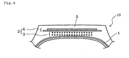
- Fig. 4 is an enlarged cross-sectional view illustrating the neighborhood of the tread portion of one embodiment of the pneumatic tire of the present invention.
- the illustrated a pneumatic radial tire 10 of the present invention has a carcass 1 as the skeleton extending in a toroidal shape between a left-and-right pair of bead portions (not shown), and has a belt layer 2 and a tread layer 5 successively arranged thereonto at the outer part in the tire radial direction.
- the belt layer 2 comprises at least one layer of circumferential belt 3, and two layers thereof in the illustrated embodiment, which layer consists of a plurality of corrugated or zigzag-shaped steel cords extending in the tire circumferential direction, and at least the relations represented by the following expressions:
- the ⁇ 2 component was measured by using an XRD equipment.
- ⁇ 2 refers to a stress applied in a direction perpendicular to the diametrical direction of the filament (sheath filament) 21 which constitutes the steel cord 20 (see Fig. 2 ).
- the filament sheath filament 21 which constitutes the steel cord 20 (see Fig. 2 ).
- the residual stress of the cord was measured by using an XRD equipment (collimator: 50 ⁇ m ⁇ , diffraction plane to be measured: ⁇ -Fe (211), diffraction angle 2 ⁇ : about 156°, radiation source: Cr).
- the bent radius of curvature R of the steel cords is within the range from 18 mm to 125 mm.
- the radius of curvature R is less than 18 mm, the relaxation of bending strain is insufficient.
- the radius of curvature R is more than 125 mm, the necessary amount of steel for a tire cannot be secured and there arise many concerns for performances.
- the radius of curvature R refers to a radius of curvature which is measured by approximating with a circular arc the bent portions of steel cord 20 processed into a corrugated or zigzag shape (see Fig. 1 ).
- the above-described steel cords 20 constituting the circumferential belt 3 be twist cords which consist of filaments having a filament diameter in the range from 0.12 mm to 0.45 mm, particularly from 0.15 mm to 0.36 mm. It is preferred that the steel cords have a cord diameter in the range from 1.20 mm to 3.00 mm, particularly from 1.20 mm to 2.00 mm, and that the initial elongation strain be in the range from 0.3% to 3.0%, particularly 0.9% to 2.0%. By using such steel cords, a more favorable cord durability can be secured.
- the initial elongation strain of the above-described steel cords exceeds 3.0%, the diameter growth by increased inner pressure becomes excessive, which makes the tread rubber on the tire surface to be in a stretched condition, thereby resulting in a deterioration of resistance to wear and anti-cut performance.
- the above-described initial elongation strain of the steel cords is less than 0.3%, the cords become fully stretched when the inner pressure of the tire is increased and at the time of diameter growth and the shape of the tire becomes abnormal due to buckling, thereby causing a deterioration of performance against partial wear.
- the initial elongation strain of a steel cord is defined by a strain-load curve of the steel cord as shown in Fig. 3 .
- the belt layer 2 preferably comprises one to four layers of the circumferential belt 3.
- the entire gauge would be too thick, thereby resulting in an increase in the weight and deterioration of the thermal durability.
- the belt layer 2 preferably comprises one to three layers of intersecting belt 4 which consists of cords extending at an angle with respect to the tire circumferential direction.
- the intersecting belt 4 is not arranged, deformation of the tire in the lateral direction may not be prevented and performance against partial wear may be deteriorated.
- the entire gauge would be too thick, which may result in an increase in the weight and deterioration of the thermal durability.
- pneumatic radial tire of the present invention relates to the improvement of the steel cords embedded in the belt layer, and other structures or materials should not be particularly restricted, and known structures and materials may be employed as appropriate.
- test tires of tire size 495/45R22.5 was produced by using a steel cord (triple layer twist: 3+9+15 structure) whose residual stress ratio L1/ L2 was varied according to the Tables 1 and 2 below, and for each of the obtained test tires, the fatigue durability of the cords in the tire was evaluated.
Landscapes
- Engineering & Computer Science (AREA)
- Mechanical Engineering (AREA)
- Tires In General (AREA)
- Ropes Or Cables (AREA)
Abstract
the belt layer comprises at least one circumferential belt which consists of a plurality of corrugated or zigzag shaped steel cords extending along the tire circumferential direction, and
at least the relations represented by the following expressions:
-0.5 ≤ L1/ L2 ≤ 0.5,
L2 ≤ 0
(where, in the case where the residual stress is a tensile stress, the stress is a + value while, in the case where the residual stress is a compressive stress, the stress is a - value) are satisfied, when the steel cords of the circumferential belt are taken out, at the inside and the outside of bent portions of the steel cords which are taken out, letting the residual stress at the inside of bent portions of the filament of a sheath portion be L1 and the residual stress at the outside of bent portions of the filament of the sheath portion be L2.
Description
- The present invention relates to a pneumatic radial tire (hereinafter, also simply referred to as "tire"). Particularly, the present invention relates to a pneumatic radial tire comprising a circumferential belt layer which consists of a plurality of corrugated or zigzag-shaped steel cords extending along the tire circumferential direction.
- Conventionally, pneumatic radial tires are provided with a circumferential belt in the tire circumferential direction as its belt layer, and it is known to apply corrugated or zigzag shaped cords to such a circumferential belt.
- For instance,
Patent Document 1 discloses a heavy-duty tire, particularly a planar tire used for trucks and buses, as well as off-the-road vehicles, which tire has a high inner pressure. Therein, a plurality of cords or filaments extending in a corrugated or zigzag shape along the equatorial plane of the tire are used as the reinforcing elements, and a plurality of ply layers in which these reinforcing elements are covered with rubber are used in place of belts consisting of cords arranged at an angle or in addition to such belts. -
- Patent Document 1: Japanese Unexamined Patent Application Publication No.
H11-245617 - However, since in the case of corrugated or zigzag shaped steel cords, the residual stress is a tensile stress at the inside of the bent portions of the steel cords, there has been a problem in that a tensile strain is likely to occur at these portions when the tire rolls. This will be a cause of decrease in durability of the steel cords.
- In addition, in a tire having a circumferential belt which consists of corrugated or zigzag-shaped steel cords, the steel cord experiences a large stress at the bent portions due to its structure. Since the circumferential belt directly receives strains during rolling of the tire, it would be subjected to repeated torsional deformation at the bent portions during rolling of the tire. Thus, there is a concern for a decrease in the durability, such as occurrence of separation, caused by an increase in energy input associated with the future increase in the tire size and planarization of tires; therefore, it is an urgent task to improve the durability of circumferential belt.
- In view of the above, the object of the present invention is to provide a pneumatic radial tire utilizing corrugated or zigzag-shaped steel cords for its circumferential belt, wherein the tire can prevent particularly the fatigue rupture of steel cords, which is a concern when energy input will be increased in the future and wherein durability of the circumferential belt is improved.
- In order to solve the above-described problems, the present inventor intensively studied to discover that the durability of a steel cord can be improved by controlling the residual stress at the bent portions of the corrugated or zigzag-shaped steel cord, thereby completing the present invention.
- That is, the pneumatic radial tire of the present invention is a pneumatic radial tire which has, as a skeleton, a carcass extending in a toroidal shape between a left-and-right pair of bead portions, and has a belt layer and tread layer successively arranged onto said carcass at the outer part in the tire radial direction, wherein
said belt layer comprises at least one circumferential belt which consists of a plurality of corrugated or zigzag shaped steel cords extending along the tire circumferential direction, and
at least the relations represented by the following expressions: - -0.5 ≤ L1/ L2 ≤0.5,
- L2 ≤ 0
- In the pneumatic radial tire of the present invention, when the steel cords of the circumferential belt are taken out, the radius of curvature R at the bent portions of the steel cords which are taken out is preferably in the range from 18 mm to 125 mm, and said steel cords of the circumferential belt are preferably twisted cords which consist of filaments having a filament diameter in the range from 0.12 mm to 0.45 mm, said steel cords having a cord diameter in the range from 1.20 mm to 3.00 mm and having an initial elongation strain in the range from 0.3% to 3.0%. Further, in the pneumatic radial tire of the present invention, said belt layer preferably comprises one to four layers of said circumferential belts, and still further, said belt layer preferably comprises one to three layers of intersecting belt consisting of cords extending at an angle with respect to the tire circumferential direction.
- In the present invention, by having the above-described constitution, the fatigue rupture of the steel cords can be effectively prevented and a pneumatic radial tire in which the durability of the circumferential belt is improved can be attained.
-
-
Fig. 1 is a schematic view illustrating a corrugated steel cord. -
Fig. 2 is a drawing explaining a stress direction σ22 which is determined in the present invention. -
Fig. 3 is a graph illustrating a strain-load curve of the steel cord. -
Fig. 4 is an enlarged cross-sectional view illustrating the neighborhood of the tread portion of one example of the pneumatic radial tire of the present invention. - A preferred embodiment of the present invention will be described in detail referring to the drawings.
-
Fig. 4 is an enlarged cross-sectional view illustrating the neighborhood of the tread portion of one embodiment of the pneumatic tire of the present invention. The illustrated a pneumaticradial tire 10 of the present invention has acarcass 1 as the skeleton extending in a toroidal shape between a left-and-right pair of bead portions (not shown), and has abelt layer 2 and atread layer 5 successively arranged thereonto at the outer part in the tire radial direction. - In the present invention, it is important that
thebelt layer 2 comprises at least one layer ofcircumferential belt 3, and two layers thereof in the illustrated embodiment, which layer consists of a plurality of corrugated or zigzag-shaped steel cords extending in the tire circumferential direction, and
at least the relations represented by the following expressions: - -0.5 ≤ L1/ L2 ≤ 0.5,
- L2 ≤ 0
- As already described, bending strains become concentrated at the bent portions in a corrugated or zigzag-shaped steel cord and depending on an increase in energy input associated with the future increase in the tire size and the like, there is a concern that a fatigue rupture of the steel cord occurs originating at such bent portions. In order to prevent this, it is effective to shift as much as possible the residual stress L1 at the inside of bent portions of the filament which is on the + (tensile) side to the - (compressive) side. The shift of the residual stress L1 from the + (tensile) side to the - (compressive) side can be performed by a presetting which shifts a tensile residual stress to the compressive side by stretching the cord. The present invention enabled to prevent the occurrence of fatigue rapture by prescribing the residual stress.
- As for the residual stress, the σ2 component was measured by using an XRD equipment. As used herein, σ2 refers to a stress applied in a direction perpendicular to the diametrical direction of the filament (sheath filament) 21 which constitutes the steel cord 20 (see
Fig. 2 ). For the cord taken out from the tire, rubber and coatings were dissolved by a solvent, and the residual stress of the cord was measured by using an XRD equipment (collimator: 50 µmφ, diffraction plane to be measured: α-Fe (211), diffraction angle 2θ: about 156°, radiation source: Cr). - When L1/ L2 is less than -0.5 under L2 ≤ 0, the residual stress L1 shifts largely to the + direction, which will be a cause of decrease in the fatigability. On the other hand, when L1/ L2 exceeds 0.5, as will be described later, the steel cords no longer have a corrugated shape or zigzag shape and a preferable initial strain ranging 0. 3% to 3. 0% cannot be secured. In order to obtain a more favorable effect of the present invention, the relations represented by
- 0 ≤ L1/L2 ≤ 0.5, and
- L2 ≤ -400
- In the present invention, it is preferred that, when the steel cords are taken out from the
circumferential belt 3, the bent radius of curvature R of the steel cords is within the range from 18 mm to 125 mm. When the radius of curvature R is less than 18 mm, the relaxation of bending strain is insufficient. On the other hand, when the radius of curvature R is more than 125 mm, the necessary amount of steel for a tire cannot be secured and there arise many concerns for performances. As used herein, the radius of curvature R refers to a radius of curvature which is measured by approximating with a circular arc the bent portions ofsteel cord 20 processed into a corrugated or zigzag shape (seeFig. 1 ). - Further, it is preferred that the above-described
steel cords 20 constituting thecircumferential belt 3 be twist cords which consist of filaments having a filament diameter in the range from 0.12 mm to 0.45 mm, particularly from 0.15 mm to 0.36 mm. It is preferred that the steel cords have a cord diameter in the range from 1.20 mm to 3.00 mm, particularly from 1.20 mm to 2.00 mm, and that the initial elongation strain be in the range from 0.3% to 3.0%, particularly 0.9% to 2.0%. By using such steel cords, a more favorable cord durability can be secured. - When the initial elongation strain of the above-described steel cords exceeds 3.0%, the diameter growth by increased inner pressure becomes excessive, which makes the tread rubber on the tire surface to be in a stretched condition, thereby resulting in a deterioration of resistance to wear and anti-cut performance. On the other hand, in cases where the above-described initial elongation strain of the steel cords is less than 0.3%, the cords become fully stretched when the inner pressure of the tire is increased and at the time of diameter growth and the shape of the tire becomes abnormal due to buckling, thereby causing a deterioration of performance against partial wear. Here, the initial elongation strain of a steel cord is defined by a strain-load curve of the steel cord as shown in
Fig. 3 . - In the pneumatic radial tire of the present invention, the
belt layer 2 preferably comprises one to four layers of thecircumferential belt 3. When the number of layers in thecircumferential belt 3 is five or more, the entire gauge would be too thick, thereby resulting in an increase in the weight and deterioration of the thermal durability. - Further, in the pneumatic radial tire of the present invention, the
belt layer 2 preferably comprises one to three layers of intersecting belt 4 which consists of cords extending at an angle with respect to the tire circumferential direction. In cases where the intersecting belt 4 is not arranged, deformation of the tire in the lateral direction may not be prevented and performance against partial wear may be deteriorated. On the other hand, when four or more layers of intersecting belt 4 are arranged, the entire gauge would be too thick, which may result in an increase in the weight and deterioration of the thermal durability. - It is noted that the pneumatic radial tire of the present invention relates to the improvement of the steel cords embedded in the belt layer, and other structures or materials should not be particularly restricted, and known structures and materials may be employed as appropriate.
- The pneumatic radial tire of the present invention will be explained concretely by way of examples thereof.
- Each of test tires of tire size 495/45R22.5 was produced by using a steel cord (triple layer twist: 3+9+15 structure) whose residual stress ratio L1/ L2 was varied according to the Tables 1 and 2 below, and for each of the obtained test tires, the fatigue durability of the cords in the tire was evaluated.
- Using evaluation conditions: normal inner pressure, and 120% of normal load, and after 70000 km running at a speed of 60 km/ h, the fatigue durability of the tire was evaluated by performing an X-ray inspection. When fatigue durability was excellent, the evaluation was represented by ⊚; when a slight cord breakages of the cords were observed but there were no problem in practical use, the evaluation was represented by ○; and when there was a cord breakage, the evaluation was represented by ×. The obtained results are shown in Tables 1 and 2 in combination.


- As shown in the above Tables 1 and 2, it was confirmed that the durability of the steel cord was able to improve in the pneumatic tires of the Examples in which corrugated steel cords satisfying the conditions according to the present invention were used for the circumferential belt.
-
- 1
- carcass
- 2
- belt layer
- 3
- circumferential belt
- 4
- intersecting belt
- 5
- tread layer
- 10
- pneumatic radial tire
- 20
- steel cord
- 21
- sheath filament
- R
- radius of curvature
- L1
- residual stress at the inside of bent portions of the filament
- L2
- residual stress at the outside of bent portions of the filament
Claims (5)
- A pneumatic radial tire which has as a skeleton a carcass extending in a toroidal shape between a left-and-right pair of bead portions, and has a belt layer and tread layer successively arranged onto said carcass at the outer part in the tire radial direction, wherein
said belt layer comprises at least one circumferential belt which consists of a plurality of corrugated or zigzag shaped steel cords extending along the tire circumferential direction, and
at least the relations represented by the following expressions:-0.5 ≤ L1/ L2 ≤ 0.5,L2 ≤ 0(where, in the case where said residual stress is a tensile stress, the stress is a + value while, in the case where said residual stress is a compressive stress, the stress is a - value) are satisfied, when the steel cords of the circumferential belt are taken out, at the inside and the outside of bent portions of the steel cords which are taken out, letting the residual stress at the inside of bent portions of the filament of a sheath portion be L1 and the residual stress at the outside of bent portions of the filament of the sheath portion be L2. - The pneumatic radial tire according to claim 1, wherein, when the steel cords of the circumferential belt are taken out, the radius of curvature R at the bent portions of the steel cords which are taken out is in the range from 18 mm to 125 mm.
- The pneumatic radial tire according to claim 1, wherein said steel cords of the circumferential belt are twisted cords which consist of filaments having a filament diameter in the range from 0.12 mm to 0.45 mm, said steel cords having a cord diameter in the range from 1.20 mm to 3.00 mm and having an initial elongation strain in the range from 0.3% to 3.0%.
- The pneumatic radial tire according to claim 1, wherein said belt layer comprises one to four layers of said circumferential belts.
- The pneumatic radial tire according to claim 1, wherein said belt layer comprises one to three layers of intersecting belt consisting of cords extending at an angle with respect to the tire circumferential direction.
Applications Claiming Priority (2)
| Application Number | Priority Date | Filing Date | Title |
|---|---|---|---|
| JP2008202327 | 2008-08-05 | ||
| PCT/JP2009/063757 WO2010016463A1 (en) | 2008-08-05 | 2009-08-03 | Pneumatic radial tire |
Publications (3)
| Publication Number | Publication Date |
|---|---|
| EP2319710A1 true EP2319710A1 (en) | 2011-05-11 |
| EP2319710A4 EP2319710A4 (en) | 2011-10-05 |
| EP2319710B1 EP2319710B1 (en) | 2014-09-24 |
Family
ID=41663680
Family Applications (1)
| Application Number | Title | Priority Date | Filing Date |
|---|---|---|---|
| EP09804946.3A Not-in-force EP2319710B1 (en) | 2008-08-05 | 2009-08-03 | Pneumatic radial tire |
Country Status (6)
| Country | Link |
|---|---|
| US (1) | US20110139327A1 (en) |
| EP (1) | EP2319710B1 (en) |
| JP (1) | JP5431330B2 (en) |
| CN (1) | CN102112328A (en) |
| ES (1) | ES2525523T3 (en) |
| WO (1) | WO2010016463A1 (en) |
Families Citing this family (2)
| Publication number | Priority date | Publication date | Assignee | Title |
|---|---|---|---|---|
| JP2023554494A (en) * | 2020-12-22 | 2023-12-27 | エンベー ベカルト ソシエテ アノニム | Steel cord for rubber reinforcement |
| CN116278540B (en) * | 2023-04-25 | 2026-01-27 | 中策橡胶集团股份有限公司 | Design method and application of passenger car tire for improving driving comfort and tire |
Family Cites Families (5)
| Publication number | Priority date | Publication date | Assignee | Title |
|---|---|---|---|---|
| US5225013A (en) * | 1989-03-14 | 1993-07-06 | Bridgestone Corporation | Pneumatic radial tire including wavy or zigzag belt cords |
| JP2942880B2 (en) * | 1992-08-27 | 1999-08-30 | 東京製綱株式会社 | Steel wire for rubber reinforcement |
| JPH11245617A (en) | 1998-03-04 | 1999-09-14 | Bridgestone Corp | Pneumatic tire |
| JP2002294573A (en) * | 2001-03-30 | 2002-10-09 | Tokusen Kogyo Co Ltd | Steel cord and tire for tire reinforcement |
| JP4903035B2 (en) * | 2006-12-27 | 2012-03-21 | 株式会社ブリヂストン | Radial tire |
-
2009
- 2009-08-03 US US13/057,637 patent/US20110139327A1/en not_active Abandoned
- 2009-08-03 WO PCT/JP2009/063757 patent/WO2010016463A1/en not_active Ceased
- 2009-08-03 ES ES09804946.3T patent/ES2525523T3/en active Active
- 2009-08-03 EP EP09804946.3A patent/EP2319710B1/en not_active Not-in-force
- 2009-08-03 JP JP2010523849A patent/JP5431330B2/en not_active Expired - Fee Related
- 2009-08-03 CN CN200980130517XA patent/CN102112328A/en active Pending
Non-Patent Citations (2)
| Title |
|---|
| No further relevant documents disclosed * |
| See also references of WO2010016463A1 * |
Also Published As
| Publication number | Publication date |
|---|---|
| JP5431330B2 (en) | 2014-03-05 |
| US20110139327A1 (en) | 2011-06-16 |
| WO2010016463A1 (en) | 2010-02-11 |
| EP2319710B1 (en) | 2014-09-24 |
| ES2525523T3 (en) | 2014-12-26 |
| JPWO2010016463A1 (en) | 2012-01-26 |
| CN102112328A (en) | 2011-06-29 |
| EP2319710A4 (en) | 2011-10-05 |
Similar Documents
| Publication | Publication Date | Title |
|---|---|---|
| US8006475B2 (en) | Steel cord for reinforcing rubber and pneumatic radial tire | |
| JP5607033B2 (en) | Steel cords for reinforcing rubber articles and pneumatic tires | |
| US20010023730A1 (en) | Tires with high strength reinforcement | |
| EP2487048A1 (en) | Run-flat tire | |
| EP1344864B1 (en) | Steel cord, method of making the same and pneumatic tire including the same | |
| EP2806057B1 (en) | Hybrid cord and tire comprising a hybrid cord | |
| JP2018502766A (en) | Tire with carcass reinforcement composed of two layers | |
| EP2168787B1 (en) | Pneumatic tire | |
| EP2248683A1 (en) | Pneumatic tire for heavy loads | |
| EP2319710B1 (en) | Pneumatic radial tire | |
| EP2218589B1 (en) | Pneumatic radial tire | |
| JP4628239B2 (en) | Steel cords for reinforcing rubber articles and pneumatic radial tires | |
| JPH07117406A (en) | Pneumatic radial tires for heavy loads | |
| EP2380755B1 (en) | Overlay ply covering the belt ply for a pneumatic tire | |
| JP2009255619A (en) | Pneumatic tire | |
| JP4409947B2 (en) | Tire with improved bead core including preformed wire | |
| JP5164538B2 (en) | Pneumatic radial tire | |
| JP4279579B2 (en) | Pneumatic radial tire | |
| JP3187601B2 (en) | Steel cord for reinforcing rubber articles and pneumatic radial tire | |
| JP4903035B2 (en) | Radial tire | |
| JP2012066816A (en) | Tire with high strength reinforcement structure | |
| JP2010115981A (en) | Pneumatic radial tire | |
| JP2005002518A (en) | Steel cord for rubber reinforcement and pneumatic radial tire | |
| JP2010155553A (en) | Pneumatic radial tire | |
| JP2005225493A (en) | Pneumatic radial-ply tire |
Legal Events
| Date | Code | Title | Description |
|---|---|---|---|
| PUAI | Public reference made under article 153(3) epc to a published international application that has entered the european phase |
Free format text: ORIGINAL CODE: 0009012 |
|
| 17P | Request for examination filed |
Effective date: 20110216 |
|
| AK | Designated contracting states |
Kind code of ref document: A1 Designated state(s): AT BE BG CH CY CZ DE DK EE ES FI FR GB GR HR HU IE IS IT LI LT LU LV MC MK MT NL NO PL PT RO SE SI SK SM TR |
|
| AX | Request for extension of the european patent |
Extension state: AL BA RS |
|
| A4 | Supplementary search report drawn up and despatched |
Effective date: 20110906 |
|
| RIC1 | Information provided on ipc code assigned before grant |
Ipc: B60C 9/20 20060101AFI20110831BHEP Ipc: B60C 9/22 20060101ALI20110831BHEP Ipc: D07B 1/06 20060101ALI20110831BHEP Ipc: B60C 9/18 20060101ALI20110831BHEP |
|
| DAX | Request for extension of the european patent (deleted) | ||
| 17Q | First examination report despatched |
Effective date: 20120727 |
|
| GRAP | Despatch of communication of intention to grant a patent |
Free format text: ORIGINAL CODE: EPIDOSNIGR1 |
|
| INTG | Intention to grant announced |
Effective date: 20140325 |
|
| GRAS | Grant fee paid |
Free format text: ORIGINAL CODE: EPIDOSNIGR3 |
|
| GRAA | (expected) grant |
Free format text: ORIGINAL CODE: 0009210 |
|
| AK | Designated contracting states |
Kind code of ref document: B1 Designated state(s): AT BE BG CH CY CZ DE DK EE ES FI FR GB GR HR HU IE IS IT LI LT LU LV MC MK MT NL NO PL PT RO SE SI SK SM TR |
|
| REG | Reference to a national code |
Ref country code: GB Ref legal event code: FG4D |
|
| REG | Reference to a national code |
Ref country code: CH Ref legal event code: EP |
|
| REG | Reference to a national code |
Ref country code: AT Ref legal event code: REF Ref document number: 688437 Country of ref document: AT Kind code of ref document: T Effective date: 20141015 |
|
| REG | Reference to a national code |
Ref country code: IE Ref legal event code: FG4D |
|
| REG | Reference to a national code |
Ref country code: DE Ref legal event code: R096 Ref document number: 602009026865 Country of ref document: DE Effective date: 20141106 |
|
| REG | Reference to a national code |
Ref country code: ES Ref legal event code: FG2A Ref document number: 2525523 Country of ref document: ES Kind code of ref document: T3 Effective date: 20141226 |
|
| PG25 | Lapsed in a contracting state [announced via postgrant information from national office to epo] |
Ref country code: GR Free format text: LAPSE BECAUSE OF FAILURE TO SUBMIT A TRANSLATION OF THE DESCRIPTION OR TO PAY THE FEE WITHIN THE PRESCRIBED TIME-LIMIT Effective date: 20141225 Ref country code: FI Free format text: LAPSE BECAUSE OF FAILURE TO SUBMIT A TRANSLATION OF THE DESCRIPTION OR TO PAY THE FEE WITHIN THE PRESCRIBED TIME-LIMIT Effective date: 20140924 Ref country code: LT Free format text: LAPSE BECAUSE OF FAILURE TO SUBMIT A TRANSLATION OF THE DESCRIPTION OR TO PAY THE FEE WITHIN THE PRESCRIBED TIME-LIMIT Effective date: 20140924 Ref country code: SE Free format text: LAPSE BECAUSE OF FAILURE TO SUBMIT A TRANSLATION OF THE DESCRIPTION OR TO PAY THE FEE WITHIN THE PRESCRIBED TIME-LIMIT Effective date: 20140924 Ref country code: NO Free format text: LAPSE BECAUSE OF FAILURE TO SUBMIT A TRANSLATION OF THE DESCRIPTION OR TO PAY THE FEE WITHIN THE PRESCRIBED TIME-LIMIT Effective date: 20141224 |
|
| REG | Reference to a national code |
Ref country code: LT Ref legal event code: MG4D Ref country code: NL Ref legal event code: VDEP Effective date: 20140924 |
|
| PG25 | Lapsed in a contracting state [announced via postgrant information from national office to epo] |
Ref country code: HR Free format text: LAPSE BECAUSE OF FAILURE TO SUBMIT A TRANSLATION OF THE DESCRIPTION OR TO PAY THE FEE WITHIN THE PRESCRIBED TIME-LIMIT Effective date: 20140924 Ref country code: LV Free format text: LAPSE BECAUSE OF FAILURE TO SUBMIT A TRANSLATION OF THE DESCRIPTION OR TO PAY THE FEE WITHIN THE PRESCRIBED TIME-LIMIT Effective date: 20140924 Ref country code: CY Free format text: LAPSE BECAUSE OF FAILURE TO SUBMIT A TRANSLATION OF THE DESCRIPTION OR TO PAY THE FEE WITHIN THE PRESCRIBED TIME-LIMIT Effective date: 20140924 |
|
| REG | Reference to a national code |
Ref country code: AT Ref legal event code: MK05 Ref document number: 688437 Country of ref document: AT Kind code of ref document: T Effective date: 20140924 |
|
| PG25 | Lapsed in a contracting state [announced via postgrant information from national office to epo] |
Ref country code: NL Free format text: LAPSE BECAUSE OF FAILURE TO SUBMIT A TRANSLATION OF THE DESCRIPTION OR TO PAY THE FEE WITHIN THE PRESCRIBED TIME-LIMIT Effective date: 20140924 |
|
| PG25 | Lapsed in a contracting state [announced via postgrant information from national office to epo] |
Ref country code: CZ Free format text: LAPSE BECAUSE OF FAILURE TO SUBMIT A TRANSLATION OF THE DESCRIPTION OR TO PAY THE FEE WITHIN THE PRESCRIBED TIME-LIMIT Effective date: 20140924 Ref country code: PT Free format text: LAPSE BECAUSE OF FAILURE TO SUBMIT A TRANSLATION OF THE DESCRIPTION OR TO PAY THE FEE WITHIN THE PRESCRIBED TIME-LIMIT Effective date: 20150126 Ref country code: SK Free format text: LAPSE BECAUSE OF FAILURE TO SUBMIT A TRANSLATION OF THE DESCRIPTION OR TO PAY THE FEE WITHIN THE PRESCRIBED TIME-LIMIT Effective date: 20140924 Ref country code: IS Free format text: LAPSE BECAUSE OF FAILURE TO SUBMIT A TRANSLATION OF THE DESCRIPTION OR TO PAY THE FEE WITHIN THE PRESCRIBED TIME-LIMIT Effective date: 20150124 Ref country code: EE Free format text: LAPSE BECAUSE OF FAILURE TO SUBMIT A TRANSLATION OF THE DESCRIPTION OR TO PAY THE FEE WITHIN THE PRESCRIBED TIME-LIMIT Effective date: 20140924 Ref country code: RO Free format text: LAPSE BECAUSE OF FAILURE TO SUBMIT A TRANSLATION OF THE DESCRIPTION OR TO PAY THE FEE WITHIN THE PRESCRIBED TIME-LIMIT Effective date: 20140924 |
|
| PG25 | Lapsed in a contracting state [announced via postgrant information from national office to epo] |
Ref country code: AT Free format text: LAPSE BECAUSE OF FAILURE TO SUBMIT A TRANSLATION OF THE DESCRIPTION OR TO PAY THE FEE WITHIN THE PRESCRIBED TIME-LIMIT Effective date: 20140924 Ref country code: PL Free format text: LAPSE BECAUSE OF FAILURE TO SUBMIT A TRANSLATION OF THE DESCRIPTION OR TO PAY THE FEE WITHIN THE PRESCRIBED TIME-LIMIT Effective date: 20140924 |
|
| REG | Reference to a national code |
Ref country code: DE Ref legal event code: R097 Ref document number: 602009026865 Country of ref document: DE |
|
| PG25 | Lapsed in a contracting state [announced via postgrant information from national office to epo] |
Ref country code: DK Free format text: LAPSE BECAUSE OF FAILURE TO SUBMIT A TRANSLATION OF THE DESCRIPTION OR TO PAY THE FEE WITHIN THE PRESCRIBED TIME-LIMIT Effective date: 20140924 |
|
| PLBE | No opposition filed within time limit |
Free format text: ORIGINAL CODE: 0009261 |
|
| STAA | Information on the status of an ep patent application or granted ep patent |
Free format text: STATUS: NO OPPOSITION FILED WITHIN TIME LIMIT |
|
| 26N | No opposition filed |
Effective date: 20150625 |
|
| PG25 | Lapsed in a contracting state [announced via postgrant information from national office to epo] |
Ref country code: SI Free format text: LAPSE BECAUSE OF FAILURE TO SUBMIT A TRANSLATION OF THE DESCRIPTION OR TO PAY THE FEE WITHIN THE PRESCRIBED TIME-LIMIT Effective date: 20140924 |
|
| PG25 | Lapsed in a contracting state [announced via postgrant information from national office to epo] |
Ref country code: MC Free format text: LAPSE BECAUSE OF FAILURE TO SUBMIT A TRANSLATION OF THE DESCRIPTION OR TO PAY THE FEE WITHIN THE PRESCRIBED TIME-LIMIT Effective date: 20140924 Ref country code: LU Free format text: LAPSE BECAUSE OF FAILURE TO SUBMIT A TRANSLATION OF THE DESCRIPTION OR TO PAY THE FEE WITHIN THE PRESCRIBED TIME-LIMIT Effective date: 20150803 |
|
| REG | Reference to a national code |
Ref country code: CH Ref legal event code: PL |
|
| GBPC | Gb: european patent ceased through non-payment of renewal fee |
Effective date: 20150803 |
|
| PG25 | Lapsed in a contracting state [announced via postgrant information from national office to epo] |
Ref country code: CH Free format text: LAPSE BECAUSE OF NON-PAYMENT OF DUE FEES Effective date: 20150831 Ref country code: LI Free format text: LAPSE BECAUSE OF NON-PAYMENT OF DUE FEES Effective date: 20150831 |
|
| REG | Reference to a national code |
Ref country code: IE Ref legal event code: MM4A |
|
| PG25 | Lapsed in a contracting state [announced via postgrant information from national office to epo] |
Ref country code: GB Free format text: LAPSE BECAUSE OF NON-PAYMENT OF DUE FEES Effective date: 20150803 Ref country code: IE Free format text: LAPSE BECAUSE OF NON-PAYMENT OF DUE FEES Effective date: 20150803 |
|
| REG | Reference to a national code |
Ref country code: FR Ref legal event code: PLFP Year of fee payment: 8 |
|
| PG25 | Lapsed in a contracting state [announced via postgrant information from national office to epo] |
Ref country code: MT Free format text: LAPSE BECAUSE OF FAILURE TO SUBMIT A TRANSLATION OF THE DESCRIPTION OR TO PAY THE FEE WITHIN THE PRESCRIBED TIME-LIMIT Effective date: 20140924 |
|
| PG25 | Lapsed in a contracting state [announced via postgrant information from national office to epo] |
Ref country code: BG Free format text: LAPSE BECAUSE OF FAILURE TO SUBMIT A TRANSLATION OF THE DESCRIPTION OR TO PAY THE FEE WITHIN THE PRESCRIBED TIME-LIMIT Effective date: 20140924 Ref country code: SM Free format text: LAPSE BECAUSE OF FAILURE TO SUBMIT A TRANSLATION OF THE DESCRIPTION OR TO PAY THE FEE WITHIN THE PRESCRIBED TIME-LIMIT Effective date: 20140924 Ref country code: HU Free format text: LAPSE BECAUSE OF FAILURE TO SUBMIT A TRANSLATION OF THE DESCRIPTION OR TO PAY THE FEE WITHIN THE PRESCRIBED TIME-LIMIT; INVALID AB INITIO Effective date: 20090803 |
|
| REG | Reference to a national code |
Ref country code: FR Ref legal event code: PLFP Year of fee payment: 9 |
|
| PG25 | Lapsed in a contracting state [announced via postgrant information from national office to epo] |
Ref country code: TR Free format text: LAPSE BECAUSE OF FAILURE TO SUBMIT A TRANSLATION OF THE DESCRIPTION OR TO PAY THE FEE WITHIN THE PRESCRIBED TIME-LIMIT Effective date: 20140924 |
|
| PG25 | Lapsed in a contracting state [announced via postgrant information from national office to epo] |
Ref country code: BE Free format text: LAPSE BECAUSE OF FAILURE TO SUBMIT A TRANSLATION OF THE DESCRIPTION OR TO PAY THE FEE WITHIN THE PRESCRIBED TIME-LIMIT Effective date: 20140924 |
|
| PG25 | Lapsed in a contracting state [announced via postgrant information from national office to epo] |
Ref country code: MK Free format text: LAPSE BECAUSE OF FAILURE TO SUBMIT A TRANSLATION OF THE DESCRIPTION OR TO PAY THE FEE WITHIN THE PRESCRIBED TIME-LIMIT Effective date: 20140924 |
|
| REG | Reference to a national code |
Ref country code: FR Ref legal event code: PLFP Year of fee payment: 10 |
|
| PGFP | Annual fee paid to national office [announced via postgrant information from national office to epo] |
Ref country code: IT Payment date: 20190829 Year of fee payment: 11 Ref country code: ES Payment date: 20190923 Year of fee payment: 11 |
|
| PGFP | Annual fee paid to national office [announced via postgrant information from national office to epo] |
Ref country code: DE Payment date: 20200819 Year of fee payment: 12 Ref country code: FR Payment date: 20200821 Year of fee payment: 12 |
|
| PG25 | Lapsed in a contracting state [announced via postgrant information from national office to epo] |
Ref country code: IT Free format text: LAPSE BECAUSE OF NON-PAYMENT OF DUE FEES Effective date: 20200803 |
|
| REG | Reference to a national code |
Ref country code: ES Ref legal event code: FD2A Effective date: 20220110 |
|
| REG | Reference to a national code |
Ref country code: DE Ref legal event code: R119 Ref document number: 602009026865 Country of ref document: DE |
|
| PG25 | Lapsed in a contracting state [announced via postgrant information from national office to epo] |
Ref country code: ES Free format text: LAPSE BECAUSE OF NON-PAYMENT OF DUE FEES Effective date: 20200804 |
|
| PG25 | Lapsed in a contracting state [announced via postgrant information from national office to epo] |
Ref country code: FR Free format text: LAPSE BECAUSE OF NON-PAYMENT OF DUE FEES Effective date: 20210831 Ref country code: DE Free format text: LAPSE BECAUSE OF NON-PAYMENT OF DUE FEES Effective date: 20220301 |