EP2317040A1 - Key for a cylinder lock - Google Patents
Key for a cylinder lock Download PDFInfo
- Publication number
- EP2317040A1 EP2317040A1 EP11153614A EP11153614A EP2317040A1 EP 2317040 A1 EP2317040 A1 EP 2317040A1 EP 11153614 A EP11153614 A EP 11153614A EP 11153614 A EP11153614 A EP 11153614A EP 2317040 A1 EP2317040 A1 EP 2317040A1
- Authority
- EP
- European Patent Office
- Prior art keywords
- key
- rib
- control
- core
- channel
- Prior art date
- Legal status (The legal status is an assumption and is not a legal conclusion. Google has not performed a legal analysis and makes no representation as to the accuracy of the status listed.)
- Granted
Links
- 238000006073 displacement reaction Methods 0.000 description 5
- 230000004323 axial length Effects 0.000 description 3
- 238000000034 method Methods 0.000 description 3
- 238000009527 percussion Methods 0.000 description 3
- 208000012886 Vertigo Diseases 0.000 description 2
- 230000001154 acute effect Effects 0.000 description 2
- 238000013461 design Methods 0.000 description 2
- 238000003780 insertion Methods 0.000 description 2
- 230000037431 insertion Effects 0.000 description 2
- 230000003993 interaction Effects 0.000 description 2
- 230000009467 reduction Effects 0.000 description 2
- 230000002441 reversible effect Effects 0.000 description 2
- 241001295925 Gegenes Species 0.000 description 1
- 230000001419 dependent effect Effects 0.000 description 1
- 238000011161 development Methods 0.000 description 1
- 230000018109 developmental process Effects 0.000 description 1
- 238000005516 engineering process Methods 0.000 description 1
- 238000004519 manufacturing process Methods 0.000 description 1
- 230000001404 mediated effect Effects 0.000 description 1
- IHQKEDIOMGYHEB-UHFFFAOYSA-M sodium dimethylarsinate Chemical class [Na+].C[As](C)([O-])=O IHQKEDIOMGYHEB-UHFFFAOYSA-M 0.000 description 1
- 238000012549 training Methods 0.000 description 1
Images


Classifications
-
- E—FIXED CONSTRUCTIONS
- E05—LOCKS; KEYS; WINDOW OR DOOR FITTINGS; SAFES
- E05B—LOCKS; ACCESSORIES THEREFOR; HANDCUFFS
- E05B27/00—Cylinder locks or other locks with tumbler pins or balls that are set by pushing the key in
- E05B27/0003—Details
- E05B27/0017—Tumblers or pins
-
- E—FIXED CONSTRUCTIONS
- E05—LOCKS; KEYS; WINDOW OR DOOR FITTINGS; SAFES
- E05B—LOCKS; ACCESSORIES THEREFOR; HANDCUFFS
- E05B19/00—Keys; Accessories therefor
- E05B19/0017—Key profiles
- E05B19/0041—Key profiles characterized by the cross-section of the key blade in a plane perpendicular to the longitudinal axis of the key
- E05B19/0052—Rectangular flat keys
- E05B19/0058—Rectangular flat keys with key bits on at least one wide side surface of the key
-
- E—FIXED CONSTRUCTIONS
- E05—LOCKS; KEYS; WINDOW OR DOOR FITTINGS; SAFES
- E05B—LOCKS; ACCESSORIES THEREFOR; HANDCUFFS
- E05B27/00—Cylinder locks or other locks with tumbler pins or balls that are set by pushing the key in
- E05B27/0057—Cylinder locks or other locks with tumbler pins or balls that are set by pushing the key in with increased picking resistance
Landscapes
- Lock And Its Accessories (AREA)
- Infusion, Injection, And Reservoir Apparatuses (AREA)
- Moulds For Moulding Plastics Or The Like (AREA)
- Component Parts Of Construction Machinery (AREA)
- Chair Legs, Seat Parts, And Backrests (AREA)
Abstract
Description
Die Erfindung betrifft einen Wendeflachschlüssel für einen Schließzylinder mit einer eine Gabelöffnung bildenden Schlüsselspitze, die zwei voneinander durch einen Kanal beabstandete schräge oder gerundete Steuerflanken besitzt zum Angriff an Steuerzonen eines Kernstiftes des Schließzylinders, wobei der Grund des Kanals eine Auflaufschräge für die Spitze des Kernstiftes ausbildet, die Auflaufschräge einer beidseitig von Nuten flankierten Rippe des Schlüssels zugeordnet ist, der Hochrippe eine Tiefrippe mit schrägen Wandungen gegenüberliegt und die Steuerflanken den Böden der Nuten zugeordnet sind.The invention relates to a turning flat key for a lock cylinder with a fork tip forming key tip having two mutually spaced by a channel oblique or rounded control edges for attacking control zones of a core pin of the lock cylinder, wherein the bottom of the channel forms a ramp for the tip of the core pin, the ramp is associated with a rib flanked by grooves on both sides of the key, the high rib is opposed by a tie rib with oblique walls and the control flanks are assigned to the bottoms of the grooves.
Aus der
In einer nicht vorveröffentlichten Druckschrift der
Dem Gegenstand der Erfindung liegt die Aufgabe zugrunde, einen gattungsgemäßen Schlüssel schließtechnisch zu verbessern.The object of the invention is based on the object to improve a generic key closing technology.
Zur Lösung der Aufgabe sieht der Anspruch 1 vor, dass sich die Steuerflanken bis in den Bereich der Tiefrippe erstrecken, sie sollen nämlich den schrägen Wandungen letzterer zugeordnet sein, also auf der selben Höhe liegen. Ferner ist vorgesehen, dass die Hochrippe die Schlüsselbreitseite überragt und der Kanal von der Tiefrippe ausgeht. Ferner sind folgende Weiterbildungen vorgesehen: Die Auflaufschräge erstreckt sich im Wesentlichen über die gesamte Schlüsseldicke. Die Steuerflanken weisen eine gerundete Gestalt auf und sind insbesondere ebenso wie die Steuerflanken konkav gerundet. Die Steuerflanken und die Auflaufschräge können unterschiedliche Winkel zur Schlüsselbreitseitenebene besitzen. Die Rippenhöhe der dem Grund des Kanal zugeordneten Tiefrippe ist bevorzugt größer als der Abstand der Scheitelfläche der Tiefrippe zum Boden einer der Tiefrippe benachbart liegenden Nut. Im Zusammenspiel mit einem passenden Schließzylinder ist die Querschnittsform der Steuerflanken den Steuerzonen des Kernstiftes formangepasst.To achieve the object, the
Da die Steuerflanken den schrägen Wandungen der Tiefrippe zugeordnet sind, wirken sie bereits nahe einer Wandung des Schlüsselkanals und können an den gerundeten Steuerzonen der Kernstifte angreifen.Since the control flanks are associated with the sloping walls of the tie rib, they already act near a wall of the keyway and can attack the rounded control zones of the core pins.
Die Steuerzonen gleiten im Wesentlichen in Linienanlage an den Steuerflanken ab. Diese weisen eine gerundete Gestalt auf. Die Spitze mindestens eines Kernstiftes bildet einen zylindrischen Fortsatz aus. Der Boden des Schlüsselkanals weist Vertiefungen auf zum Eintritt der Spitze oder des zylin-drischen Fortsatzes des mindestens eines Kernstiftes. Der Grund des Kanals bildet eine Auflaufschräge für die Spitze des Kernstiftes aus. Diese tritt erst nach einer Anfangsverlagerung durch die Steuerflanken gegen die Auflaufschräge. Der Schlüssel ist als Wendeflachschlüssel ausgestaltet. Eine Vielzahl von in Einsteckrichtung des Schlüssels hintereinanderliegender Kernstifte sind in dem Schließzylinder angeordnet. Ein oder mehrere Kernstifte bilden an ihren Spitzen zylindrische Fortsätze aus. Die Auflaufschräge ist einer Tiefrippe sowie einer Hochrippe des Schlüssels zugeordnet. Die Auflaufschräge erstreckt sich über im Wesentlichen die gesamte Schlüsseldicke. Den Böden zweier eine Hochrippe flankierenden Nut sind die Steuerflanken zugeordnet. Diese können auch den schrägen Wandungen einer Tiefrippe zugeordnet sein. Die Steuerzonen und die Auflaufschrägen besitzen unterschiedliche Winkel zur Schlüsselkanalebene. Die axiale Länge der Steuerzonen ist geringfügig größer als die Rippenhöhe einer dem Grund des Kanals zugeordneten Tiefrippe, aber geringer ist als der Abstand der Scheitelfläche der Tiefrippe zum Boden einer der Tiefrippe benachbart liegenden Nut. Des Weiteren ist ein Schlüssel für ein Schließzylinder vorgesehen, bei dem die Steuerflanken gerundet sind.The control zones essentially slide off in the line system on the control flanks. These have a rounded shape. The tip of at least one core pin forms a cylindrical extension. The bottom of the keyway has recesses to the entrance of the tip or the cylin-drical extension of at least one core pin. The bottom of the channel forms a ramp for the tip of the core pin. This occurs only after an initial shift by the control edges against the ramp. The key is designed as a reversible flat key. A plurality of in the insertion direction of the key one behind the other core pins are arranged in the lock cylinder. One or more core pins form at their tips cylindrical extensions. The ramp is associated with a Tiefrippe and a high rib of the key. The ramp extends over substantially the entire key thickness. The bottoms of two grooves flanking a high rib are assigned the control edges. These can also be assigned to the oblique walls of a deep rib. The control zones and the ramps have different angles to the key channel plane. The axial length of the control zones is slightly greater than the rib height of a tie rib associated with the bottom of the channel, but less than the pitch of the top surface of the tie rib to the bottom of a groove adjacent the tie rib. Furthermore, a key is provided for a lock cylinder, in which the control edges are rounded.
Die zuvor beschriebene Erfindung soll anhand mehrerer Ausführungsbeispiele näher erläutert werden. Es zeigen:
- Fig. 1
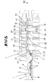
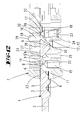
- einen erfindungsgemäßen Schlüssel in einer perspektivischen Ansicht,
- Fig. 2
- eine Ausschnittsvergrößerung der Schlüsselspitze entsprechend des Ausschnitts II aus
Fig. 1 , - Fig. 3
- eine Ansicht auf die Schlüsselspitze in Blickrichtung III aus
Fig. 1 , - Fig. 4
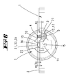
- eine perspektivischer Halbschnitt eines Zylinderkerns mit den Kernstiften und einem Zusatzstift,
- Fig. 5
- eine Ansicht des Zylinderkerns entsprechend der Blickrichtung V aus
Fig. 4 , jedoch greifen die Steuerflanken der Schlüsselspitze an den Steuerzonen des ersten Kernstifts an, - Fig. 6
- eine Seitenansicht gemäß der Blickrichtung VI aus
Fig. 5 , - Fig. 7
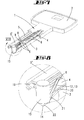
- eine perspektivische Ansicht des Schlüssels mit dem ersten Kernstift,
- Fig. 8
- eine Ausschnittsvergrößerung entsprechend des Ausschnitts VIII aus
Fig. 7 , - Fig. 9
- eine ähnliche Darstellung wie
Fig. 5 , jedoch greift jetzt die Auflaufschräge der Schlüsselspitze an der Spitze des ersten Kernstiftes an, - Fig. 10
- eine ähnliche Darstellung wie
Fig. 7 , jedoch in der Stellung, die inFig. 9 verdeutlicht ist, - Fig. 11
- eine Ausschnittsvergrößerung entsprechend des Ausschnittes XI aus
Fig. 10 , - Fig. 12
- eine Ansicht entsprechend der
Fig. 5 , jedoch greift die Schlüsselspitze mit ihren Steuerflanken an einem anderen Kernstift an, der einen zylindrischen Fortsatz ausbildet, - Fig. 13
- eine Ansicht entsprechend der
Fig. 7 , jedoch mit dem anderen Kernstift und in der Stellung, die inFig. 12 verdeutlicht ist, - Fig. 14
- eine Ausschnittsvergrößerung entsprechend des Ausschnittes XIV aus
Fig. 13 , - Fig. 15
- eine Ansicht entsprechend der
Fig. 12 , jedoch greift jetzt die Auflaufschräge der Schlüsselspitze an dem zylindrischen Fortsatz des Kernstiftes an, - Fig. 16
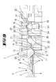
- eine ähnliche Darstellung wie
Fig. 13 , jedoch in der Stellung, die inFig. 15 verdeutlicht worden ist und - Fig. 17
- eine Ausschnittsvergrößerung entsprechend des Ausschnittes XVII aus
Fig. 16 .
- Fig. 1
- a key according to the invention in a perspective view,
- Fig. 2
- a detail enlargement of the key top according to the clipping II
Fig. 1 . - Fig. 3
- a view of the key tip in the direction of III from
Fig. 1 . - Fig. 4
- a perspective half section of a cylinder core with the core pins and an additional pin,
- Fig. 5
- a view of the cylinder core according to the viewing direction V from
Fig. 4 but the control flanks of the key tip engage the control zones of the first core pin, - Fig. 6
- a side view according to the viewing direction VI
Fig. 5 . - Fig. 7
- a perspective view of the key with the first core pin,
- Fig. 8
- an enlarged detail corresponding to the section VIII
Fig. 7 . - Fig. 9
- a similar representation as
Fig. 5 but now the run-on slope of the key tip engages the tip of the first core pin, - Fig. 10
- a similar representation as
Fig. 7 , but in the position inFig. 9 is clear - Fig. 11
- a detail enlargement corresponding to the section XI
Fig. 10 . - Fig. 12
- a view corresponding to the
Fig. 5 However, the key tip attacks with its control edges on another core pin, which forms a cylindrical extension, - Fig. 13
- a view corresponding to the
Fig. 7 but with the other core pin and in the position inFig. 12 is clear - Fig. 14
- a detail enlargement corresponding to the section XIV
Fig. 13 . - Fig. 15
- a view corresponding to the
Fig. 12 , but now the ramp of the key tip engages the cylindrical extension of the core pin, - Fig. 16
- a similar representation as
Fig. 13 , but in the position inFig. 15 has been clarified and - Fig. 17
- an excerpt from the section XVII
Fig. 16 ,
Die Tiefrippe 5 weist eine Stufe 8 auf. Diese geht in einen höhenverminderten Tiefrippenbereich 5' über. Vor der Stufe 8 in Richtung der Schlüsselspitze ist eine Senkung 9 eingearbeitet. In die Senkung 9 kann ein Zusatzstift 10 hineingreifen.The
In
Die Schlüsselspitze bildet eine Gabelöffnung 19 aus. Mit dieser Gabelöffnung 19 kann die Schlüsselspitze den zylindrischen Fortsatzes 17 des Kernstiftes 18 umragen.The key tip forms a
Seitlich der Hochrippe befindet sich jeweils eine Nut 20. Die beiden Nuten 20 flankieren die Hochrippe 4. Den Böden der Nuten 20 ist jeweils eine Steuerflanke 21 zugeordnet. Somit sind die Steuerflanken 21 auch den schrägen Wandungen der Tiefrippe 5 zugeordnet. Die Steuerflanken 21 weisen eine gerundete Gestalt auf und sind somit der Form der Steuerzonen 22 der Kernstifte 15,18 formangepasst.Each side of the high rib is a
In der
In dem Zylinderkern 7 sind für die Kernstifte 15, 18 Kernstiftbohrungen 25 vorgesehen. Diese verlaufen in einem rechten Winkel zur Verlaufsrichtung des Schlüsselkanals 11. Die Kernstiftbohrungen 25 sind in der
Die Kernstifte 15, 18 sind rotationssymmetrisch gestaltet. Durch die rotationssymmetrische Gestalt der Kernstifte 15, 18 wird eine kostengünstigere Fertigung erzielt.The core pins 15, 18 are designed rotationally symmetrical. Due to the rotationally symmetrical shape of the core pins 15, 18 a more cost-effective production is achieved.
Die an der Schlüsselspitze eingearbeitete Auflaufschräge 13 und die Steuerflanken 21 können einen unterschiedlichen Winkel zur Schlüsselkanalebene besitzen. Durch unterschiedliche Winkel zueinander wird erreicht, dass sich der Kernstift 15, 18 je nach Winkel unterschiedlich schnell bei gleichbleibender Einsteckgeschwindigkeit des Schlüssels 1 verlagert. Beispielsweise können die Steuerflanken 21 einen spitzeren Winkel zur Schlüsselkanalebene aufweisen als die Auflaufschräge 13. Durch diese Gestaltung wird erreicht, dass am Anfang die Kernstifte 15,18 langsam verlagert werden und somit ein Verkanten der Kernstifte 15, 18 im Zylinderkern 7 verhindert wird. Gleiten die Kernstifte 15, 18 anschließend auf der Auflaufschräge 13 ab, so verlagern sich diese schneller. In
Es stellt sich folgende Wirkungsweise ein:
- Ausgehend von der
Fig. 4 sind dieKernstifte Die Kernstifte Richtung des Schlüsselkanals 11. In dieser Position würden dieGehäusestifte den Zylinderkern 7 gegen ein Drehen sichern. Erst durch einen passenden Schlüssel 1 wäre es möglich, dieKernstifte den Kernstiften
- Starting from the
Fig. 4 are the core pins 15, 18 and theadditional pin 10 in its normal position. The core pins 15, 18 are part of a tumbler, which is not shown here. To the tumbler still include housing pins, which are acted upon by springs. The springs act in the direction of thekey channel 11. In this position, the housing pins would secure thecylinder core 7 against rotation. Only by a matchingkey 1, it would be possible to relocate the core pins 15, 18 and the housing pins, not shown, such that the parting plane between the core pins 15, 18 and the housing pins is aligned with the lateral surface of thecylinder core 7. Then it is only possible to turn the cylinder core.
In der
Wie in den
Wird nun der Schlüssel 1 vollständig in den Schlüsselkanal 11 eingesteckt, verlagern sich die Kernstifte 15, 18 derart, dass jede Spitze 14, 16 in einer passenden Senkung 6 des Schlüsselschaftes 3 einliegt. Der Konusabschnitt 30 des Zusatzstiftes 10 liegt dann in der Senkung 9 der gegenüberliegenden Tiefrippe 5 ein. Werden nun, wie in der
Durch die rotationssymmetrische Gestaltung der Kernstifte 15,18 wird erreicht, dass diese kostengünstiger hergestellt werden können und die dafür vorgesehenen Kernstiftbohrungen 25 nicht mehr für den Profilquerschnitt der sonstigen Kernstifte angepasst werden muss. Ebenfalls braucht nicht mehr darauf geachtet zu werden, dass die Kernstifte 15,18 in einer bestimmten Stellung zu den Kernstiftbohrungen 25 eingesetzt werden. Da die Kernstifte 15, 18 keinen Steg mehr ausbilden, sind diese stabiler gestaltet. Durch die Linienanlage der Steuerzonen 22 an den Steuerflanken 21 wird ein geringerer Verschleiß erreicht.Due to the rotationally symmetrical design of the core pins 15,18 ensures that they can be produced more cheaply and the designated core pin holes 25 no longer needs to be adapted for the profile cross section of the other core pins. Likewise, it no longer needs to be taken to ensure that the core pins 15, 18 are inserted in a specific position relative to the core pin bores 25. Since the core pins 15, 18 no Bridge more training, these are designed more stable. Due to the line system of the
Claims (7)
Applications Claiming Priority (2)
| Application Number | Priority Date | Filing Date | Title |
|---|---|---|---|
| DE102005024003A DE102005024003B4 (en) | 2005-05-25 | 2005-05-25 | Lock cylinder with a key |
| EP06113875A EP1726749B1 (en) | 2005-05-25 | 2006-05-12 | Cylinder lock with a key |
Related Parent Applications (1)
| Application Number | Title | Priority Date | Filing Date |
|---|---|---|---|
| EP06113875.6 Division | 2006-05-12 |
Publications (2)
| Publication Number | Publication Date |
|---|---|
| EP2317040A1 true EP2317040A1 (en) | 2011-05-04 |
| EP2317040B1 EP2317040B1 (en) | 2012-06-20 |
Family
ID=36985460
Family Applications (2)
| Application Number | Title | Priority Date | Filing Date |
|---|---|---|---|
| EP11153614A Active EP2317040B1 (en) | 2005-05-25 | 2006-05-12 | Key for a cylinder lock |
| EP06113875A Active EP1726749B1 (en) | 2005-05-25 | 2006-05-12 | Cylinder lock with a key |
Family Applications After (1)
| Application Number | Title | Priority Date | Filing Date |
|---|---|---|---|
| EP06113875A Active EP1726749B1 (en) | 2005-05-25 | 2006-05-12 | Cylinder lock with a key |
Country Status (4)
| Country | Link |
|---|---|
| EP (2) | EP2317040B1 (en) |
| AT (1) | ATE515614T1 (en) |
| DE (1) | DE102005024003B4 (en) |
| ES (2) | ES2387380T3 (en) |
Cited By (2)
| Publication number | Priority date | Publication date | Assignee | Title |
|---|---|---|---|---|
| EP4063594A1 (en) * | 2021-03-24 | 2022-09-28 | MG Serrature S.p.A. | Reversible flat key and cylinder lock with reversible flat key |
| WO2023041517A1 (en) * | 2021-09-14 | 2023-03-23 | Dormakaba Austria Gmbh | Key or key blank, production method and lock system |
Families Citing this family (2)
| Publication number | Priority date | Publication date | Assignee | Title |
|---|---|---|---|---|
| EP2890856B1 (en) * | 2012-08-29 | 2017-04-12 | dormakaba Schweiz AG | Blank, security key, lock system, and production method |
| ITBO20120662A1 (en) | 2012-12-10 | 2014-06-11 | Filippo Bastianini | LOCK WITH MECHANICALLY REPROGRAMMABLE DISK LOCK AND KEY FOR THE SAME |
Citations (6)
| Publication number | Priority date | Publication date | Assignee | Title |
|---|---|---|---|---|
| GB130003A (en) * | 1916-11-25 | 1919-07-31 | Frederick William Schroeder | Improvements in Pin Tumbler Locks. |
| DE3832143A1 (en) * | 1988-09-22 | 1990-04-05 | Dom Sicherheitstechnik | LOCKING DEVICE, COMPOSED OF LOCKING CYLINDER AND FLAT KEY |
| US5222383A (en) * | 1992-05-08 | 1993-06-29 | Tong-Lung Metal Industry Co., Ltd. | Cylinder lock |
| US5438857A (en) * | 1989-12-15 | 1995-08-08 | Bauer Kaba Ag | Lock cylinder and key as well as key blank with matched security device |
| DE20115848U1 (en) * | 2001-07-20 | 2002-01-10 | Lou Chi Wen | Locking device with an associated key |
| DE102004003034A1 (en) | 2003-10-17 | 2005-05-19 | Dom Sicherheitstechnik Gmbh & Co Kg | Cylinder lock for use with flat key has pins of different length in rotatable cylinder with sharp ends engaging key with security pattern in one profiled broad side |
Family Cites Families (2)
| Publication number | Priority date | Publication date | Assignee | Title |
|---|---|---|---|---|
| DE1876909U (en) * | 1963-06-06 | 1963-08-01 | Karrenberg Fa Wilhelm | LOCK CYLINDER WITH MUSHROOM-SHAPED HOUSING PINS. |
| TWI238216B (en) * | 2002-06-28 | 2005-08-21 | Hsien-Lung Tseng | Key and lock with buried beads on slant shaft |
-
2005
- 2005-05-25 DE DE102005024003A patent/DE102005024003B4/en not_active Expired - Fee Related
-
2006
- 2006-05-12 AT AT06113875T patent/ATE515614T1/en active
- 2006-05-12 ES ES11153614T patent/ES2387380T3/en active Active
- 2006-05-12 EP EP11153614A patent/EP2317040B1/en active Active
- 2006-05-12 EP EP06113875A patent/EP1726749B1/en active Active
- 2006-05-12 ES ES06113875T patent/ES2365806T3/en active Active
Patent Citations (7)
| Publication number | Priority date | Publication date | Assignee | Title |
|---|---|---|---|---|
| GB130003A (en) * | 1916-11-25 | 1919-07-31 | Frederick William Schroeder | Improvements in Pin Tumbler Locks. |
| DE3832143A1 (en) * | 1988-09-22 | 1990-04-05 | Dom Sicherheitstechnik | LOCKING DEVICE, COMPOSED OF LOCKING CYLINDER AND FLAT KEY |
| DE3832143C2 (en) | 1988-09-22 | 1990-10-04 | Dom-Sicherheitstechnik Gmbh & Co Kg, 5040 Bruehl, De | |
| US5438857A (en) * | 1989-12-15 | 1995-08-08 | Bauer Kaba Ag | Lock cylinder and key as well as key blank with matched security device |
| US5222383A (en) * | 1992-05-08 | 1993-06-29 | Tong-Lung Metal Industry Co., Ltd. | Cylinder lock |
| DE20115848U1 (en) * | 2001-07-20 | 2002-01-10 | Lou Chi Wen | Locking device with an associated key |
| DE102004003034A1 (en) | 2003-10-17 | 2005-05-19 | Dom Sicherheitstechnik Gmbh & Co Kg | Cylinder lock for use with flat key has pins of different length in rotatable cylinder with sharp ends engaging key with security pattern in one profiled broad side |
Cited By (2)
| Publication number | Priority date | Publication date | Assignee | Title |
|---|---|---|---|---|
| EP4063594A1 (en) * | 2021-03-24 | 2022-09-28 | MG Serrature S.p.A. | Reversible flat key and cylinder lock with reversible flat key |
| WO2023041517A1 (en) * | 2021-09-14 | 2023-03-23 | Dormakaba Austria Gmbh | Key or key blank, production method and lock system |
Also Published As
| Publication number | Publication date |
|---|---|
| EP1726749A3 (en) | 2007-11-28 |
| EP1726749A2 (en) | 2006-11-29 |
| ES2365806T3 (en) | 2011-10-11 |
| ES2387380T3 (en) | 2012-09-21 |
| ATE515614T1 (en) | 2011-07-15 |
| DE102005024003B4 (en) | 2007-02-08 |
| DE102005024003A1 (en) | 2006-11-30 |
| EP1726749B1 (en) | 2011-07-06 |
| EP2317040B1 (en) | 2012-06-20 |
Similar Documents
| Publication | Publication Date | Title |
|---|---|---|
| EP0335069B1 (en) | Flat key for cylinder locks, and cylinder lock for this key | |
| DE3827687C2 (en) | ||
| EP1055788B1 (en) | Flat key and cylinder lock | |
| EP1712714B1 (en) | Combination of a flat key and a cylinder lock | |
| EP3409865B1 (en) | Lock cylinder with associated key | |
| EP2317040B1 (en) | Key for a cylinder lock | |
| EP2803793A2 (en) | Lock cylinder with pulling pin which engages with a protrusion extending from the broad side of the key | |
| EP2890856B1 (en) | Blank, security key, lock system, and production method | |
| DE4108668B4 (en) | Locking cylinder key | |
| EP2264264B1 (en) | Locking device and key for a locking device | |
| DE102010012261B4 (en) | locking system | |
| DE102013103790B4 (en) | lock cylinder | |
| EP1333136B1 (en) | Lock cylinder | |
| EP2360334A2 (en) | Locking cylinder | |
| DE2135106B2 (en) | Cylinder lock with paired tumbler plates - is operated by key with actuating ridge faces on both sides | |
| EP3085860B1 (en) | Closing device | |
| WO2008074171A1 (en) | Locking system with security turning keys | |
| EP1057953B1 (en) | Lock cylinder and corresponding key | |
| EP3095931B1 (en) | Lock cylinder and lock system with such a lock cylinder | |
| EP1333135A1 (en) | Lock cylinder | |
| DE102006044106A1 (en) | Locking system comprises a shoulder which lies in a chamfered recess on a control side when a key is completely inserted | |
| DE3245856A1 (en) | Lock cylinder | |
| DE19732450B4 (en) | Reversible key lock cylinder | |
| CH689493A5 (en) | Cylinder lock with cylinder housing in which rotatable cylinder core is located | |
| EP4119750A1 (en) | Locking cylinder and locking system |
Legal Events
| Date | Code | Title | Description |
|---|---|---|---|
| PUAI | Public reference made under article 153(3) epc to a published international application that has entered the european phase |
Free format text: ORIGINAL CODE: 0009012 |
|
| AC | Divisional application: reference to earlier application |
Ref document number: 1726749 Country of ref document: EP Kind code of ref document: P |
|
| AK | Designated contracting states |
Kind code of ref document: A1 Designated state(s): AT BE BG CH CY CZ DE DK EE ES FI FR GB GR HU IE IS IT LI LT LU LV MC NL PL PT RO SE SI SK TR |
|
| AX | Request for extension of the european patent |
Extension state: AL BA HR MK YU |
|
| 17P | Request for examination filed |
Effective date: 20110902 |
|
| GRAP | Despatch of communication of intention to grant a patent |
Free format text: ORIGINAL CODE: EPIDOSNIGR1 |
|
| RIC1 | Information provided on ipc code assigned before grant |
Ipc: E05B 19/06 20060101ALI20120124BHEP Ipc: E05B 27/10 20060101AFI20120124BHEP |
|
| GRAS | Grant fee paid |
Free format text: ORIGINAL CODE: EPIDOSNIGR3 |
|
| GRAA | (expected) grant |
Free format text: ORIGINAL CODE: 0009210 |
|
| AC | Divisional application: reference to earlier application |
Ref document number: 1726749 Country of ref document: EP Kind code of ref document: P |
|
| AK | Designated contracting states |
Kind code of ref document: B1 Designated state(s): AT BE BG CH CY CZ DE DK EE ES FI FR GB GR HU IE IS IT LI LT LU LV MC NL PL PT RO SE SI SK TR |
|
| REG | Reference to a national code |
Ref country code: GB Ref legal event code: FG4D Free format text: NOT ENGLISH |
|
| REG | Reference to a national code |
Ref country code: DE Ref legal event code: R082 Ref document number: 502006011640 Country of ref document: DE Representative=s name: RIEDER & PARTNER PATENTANWAELTE - RECHTSANWALT, DE Ref country code: DE Ref legal event code: R082 Ref document number: 502006011640 Country of ref document: DE Representative=s name: WITTE, WELLER & PARTNER PATENTANWAELTE MBB, DE |
|
| REG | Reference to a national code |
Ref country code: CH Ref legal event code: EP Ref country code: CH Ref legal event code: NV Representative=s name: R. A. EGLI & CO. PATENTANWAELTE |
|
| REG | Reference to a national code |
Ref country code: AT Ref legal event code: REF Ref document number: 563186 Country of ref document: AT Kind code of ref document: T Effective date: 20120715 |
|
| REG | Reference to a national code |
Ref country code: IE Ref legal event code: FG4D Free format text: LANGUAGE OF EP DOCUMENT: GERMAN |
|
| REG | Reference to a national code |
Ref country code: NL Ref legal event code: T3 |
|
| REG | Reference to a national code |
Ref country code: DE Ref legal event code: R096 Ref document number: 502006011640 Country of ref document: DE Effective date: 20120816 |
|
| REG | Reference to a national code |
Ref country code: ES Ref legal event code: FG2A Ref document number: 2387380 Country of ref document: ES Kind code of ref document: T3 Effective date: 20120921 |
|
| PG25 | Lapsed in a contracting state [announced via postgrant information from national office to epo] |
Ref country code: LT Free format text: LAPSE BECAUSE OF FAILURE TO SUBMIT A TRANSLATION OF THE DESCRIPTION OR TO PAY THE FEE WITHIN THE PRESCRIBED TIME-LIMIT Effective date: 20120620 Ref country code: SE Free format text: LAPSE BECAUSE OF FAILURE TO SUBMIT A TRANSLATION OF THE DESCRIPTION OR TO PAY THE FEE WITHIN THE PRESCRIBED TIME-LIMIT Effective date: 20120620 Ref country code: FI Free format text: LAPSE BECAUSE OF FAILURE TO SUBMIT A TRANSLATION OF THE DESCRIPTION OR TO PAY THE FEE WITHIN THE PRESCRIBED TIME-LIMIT Effective date: 20120620 |
|
| REG | Reference to a national code |
Ref country code: LT Ref legal event code: MG4D Effective date: 20120620 |
|
| PG25 | Lapsed in a contracting state [announced via postgrant information from national office to epo] |
Ref country code: LV Free format text: LAPSE BECAUSE OF FAILURE TO SUBMIT A TRANSLATION OF THE DESCRIPTION OR TO PAY THE FEE WITHIN THE PRESCRIBED TIME-LIMIT Effective date: 20120620 Ref country code: GR Free format text: LAPSE BECAUSE OF FAILURE TO SUBMIT A TRANSLATION OF THE DESCRIPTION OR TO PAY THE FEE WITHIN THE PRESCRIBED TIME-LIMIT Effective date: 20120921 Ref country code: SI Free format text: LAPSE BECAUSE OF FAILURE TO SUBMIT A TRANSLATION OF THE DESCRIPTION OR TO PAY THE FEE WITHIN THE PRESCRIBED TIME-LIMIT Effective date: 20120620 |
|
| PG25 | Lapsed in a contracting state [announced via postgrant information from national office to epo] |
Ref country code: EE Free format text: LAPSE BECAUSE OF FAILURE TO SUBMIT A TRANSLATION OF THE DESCRIPTION OR TO PAY THE FEE WITHIN THE PRESCRIBED TIME-LIMIT Effective date: 20120620 Ref country code: SK Free format text: LAPSE BECAUSE OF FAILURE TO SUBMIT A TRANSLATION OF THE DESCRIPTION OR TO PAY THE FEE WITHIN THE PRESCRIBED TIME-LIMIT Effective date: 20120620 Ref country code: RO Free format text: LAPSE BECAUSE OF FAILURE TO SUBMIT A TRANSLATION OF THE DESCRIPTION OR TO PAY THE FEE WITHIN THE PRESCRIBED TIME-LIMIT Effective date: 20120620 Ref country code: CY Free format text: LAPSE BECAUSE OF FAILURE TO SUBMIT A TRANSLATION OF THE DESCRIPTION OR TO PAY THE FEE WITHIN THE PRESCRIBED TIME-LIMIT Effective date: 20120620 Ref country code: IS Free format text: LAPSE BECAUSE OF FAILURE TO SUBMIT A TRANSLATION OF THE DESCRIPTION OR TO PAY THE FEE WITHIN THE PRESCRIBED TIME-LIMIT Effective date: 20121020 Ref country code: CZ Free format text: LAPSE BECAUSE OF FAILURE TO SUBMIT A TRANSLATION OF THE DESCRIPTION OR TO PAY THE FEE WITHIN THE PRESCRIBED TIME-LIMIT Effective date: 20120620 |
|
| PG25 | Lapsed in a contracting state [announced via postgrant information from national office to epo] |
Ref country code: PL Free format text: LAPSE BECAUSE OF FAILURE TO SUBMIT A TRANSLATION OF THE DESCRIPTION OR TO PAY THE FEE WITHIN THE PRESCRIBED TIME-LIMIT Effective date: 20120620 Ref country code: PT Free format text: LAPSE BECAUSE OF FAILURE TO SUBMIT A TRANSLATION OF THE DESCRIPTION OR TO PAY THE FEE WITHIN THE PRESCRIBED TIME-LIMIT Effective date: 20121022 |
|
| PLBE | No opposition filed within time limit |
Free format text: ORIGINAL CODE: 0009261 |
|
| STAA | Information on the status of an ep patent application or granted ep patent |
Free format text: STATUS: NO OPPOSITION FILED WITHIN TIME LIMIT |
|
| PG25 | Lapsed in a contracting state [announced via postgrant information from national office to epo] |
Ref country code: DK Free format text: LAPSE BECAUSE OF FAILURE TO SUBMIT A TRANSLATION OF THE DESCRIPTION OR TO PAY THE FEE WITHIN THE PRESCRIBED TIME-LIMIT Effective date: 20120620 |
|
| 26N | No opposition filed |
Effective date: 20130321 |
|
| REG | Reference to a national code |
Ref country code: DE Ref legal event code: R097 Ref document number: 502006011640 Country of ref document: DE Effective date: 20130321 |
|
| PG25 | Lapsed in a contracting state [announced via postgrant information from national office to epo] |
Ref country code: BG Free format text: LAPSE BECAUSE OF FAILURE TO SUBMIT A TRANSLATION OF THE DESCRIPTION OR TO PAY THE FEE WITHIN THE PRESCRIBED TIME-LIMIT Effective date: 20120920 |
|
| PG25 | Lapsed in a contracting state [announced via postgrant information from national office to epo] |
Ref country code: MC Free format text: LAPSE BECAUSE OF FAILURE TO SUBMIT A TRANSLATION OF THE DESCRIPTION OR TO PAY THE FEE WITHIN THE PRESCRIBED TIME-LIMIT Effective date: 20120620 |
|
| REG | Reference to a national code |
Ref country code: IE Ref legal event code: MM4A |
|
| PG25 | Lapsed in a contracting state [announced via postgrant information from national office to epo] |
Ref country code: IE Free format text: LAPSE BECAUSE OF NON-PAYMENT OF DUE FEES Effective date: 20130512 |
|
| REG | Reference to a national code |
Ref country code: DE Ref legal event code: R082 Ref document number: 502006011640 Country of ref document: DE Representative=s name: WITTE, WELLER & PARTNER PATENTANWAELTE MBB, DE |
|
| PG25 | Lapsed in a contracting state [announced via postgrant information from national office to epo] |
Ref country code: TR Free format text: LAPSE BECAUSE OF FAILURE TO SUBMIT A TRANSLATION OF THE DESCRIPTION OR TO PAY THE FEE WITHIN THE PRESCRIBED TIME-LIMIT Effective date: 20120620 |
|
| PG25 | Lapsed in a contracting state [announced via postgrant information from national office to epo] |
Ref country code: LU Free format text: LAPSE BECAUSE OF NON-PAYMENT OF DUE FEES Effective date: 20130512 Ref country code: HU Free format text: LAPSE BECAUSE OF FAILURE TO SUBMIT A TRANSLATION OF THE DESCRIPTION OR TO PAY THE FEE WITHIN THE PRESCRIBED TIME-LIMIT; INVALID AB INITIO Effective date: 20060512 |
|
| REG | Reference to a national code |
Ref country code: FR Ref legal event code: PLFP Year of fee payment: 11 |
|
| REG | Reference to a national code |
Ref country code: FR Ref legal event code: PLFP Year of fee payment: 12 |
|
| REG | Reference to a national code |
Ref country code: FR Ref legal event code: PLFP Year of fee payment: 13 |
|
| PGFP | Annual fee paid to national office [announced via postgrant information from national office to epo] |
Ref country code: GB Payment date: 20200522 Year of fee payment: 15 |
|
| GBPC | Gb: european patent ceased through non-payment of renewal fee |
Effective date: 20210512 |
|
| PG25 | Lapsed in a contracting state [announced via postgrant information from national office to epo] |
Ref country code: GB Free format text: LAPSE BECAUSE OF NON-PAYMENT OF DUE FEES Effective date: 20210512 |
|
| PGFP | Annual fee paid to national office [announced via postgrant information from national office to epo] |
Ref country code: NL Payment date: 20230519 Year of fee payment: 18 Ref country code: IT Payment date: 20230525 Year of fee payment: 18 Ref country code: FR Payment date: 20230523 Year of fee payment: 18 Ref country code: ES Payment date: 20230621 Year of fee payment: 18 Ref country code: CH Payment date: 20230605 Year of fee payment: 18 |
|
| PGFP | Annual fee paid to national office [announced via postgrant information from national office to epo] |
Ref country code: AT Payment date: 20230519 Year of fee payment: 18 |
|
| PGFP | Annual fee paid to national office [announced via postgrant information from national office to epo] |
Ref country code: BE Payment date: 20230522 Year of fee payment: 18 |
|
| PGFP | Annual fee paid to national office [announced via postgrant information from national office to epo] |
Ref country code: DE Payment date: 20230731 Year of fee payment: 18 |