EP2316712A1 - Verbundprofil bestehend aus wenigstens einem ersten und zweiten Metallprofilteil - Google Patents
Verbundprofil bestehend aus wenigstens einem ersten und zweiten Metallprofilteil Download PDFInfo
- Publication number
- EP2316712A1 EP2316712A1 EP10013838A EP10013838A EP2316712A1 EP 2316712 A1 EP2316712 A1 EP 2316712A1 EP 10013838 A EP10013838 A EP 10013838A EP 10013838 A EP10013838 A EP 10013838A EP 2316712 A1 EP2316712 A1 EP 2316712A1
- Authority
- EP
- European Patent Office
- Prior art keywords
- metal profile
- profile part
- metal
- composite
- joint
- Prior art date
- Legal status (The legal status is an assumption and is not a legal conclusion. Google has not performed a legal analysis and makes no representation as to the accuracy of the status listed.)
- Granted
Links
Images
Classifications
-
- B—PERFORMING OPERATIONS; TRANSPORTING
- B62—LAND VEHICLES FOR TRAVELLING OTHERWISE THAN ON RAILS
- B62D—MOTOR VEHICLES; TRAILERS
- B62D25/00—Superstructure or monocoque structure sub-units; Parts or details thereof not otherwise provided for
-
- B—PERFORMING OPERATIONS; TRANSPORTING
- B23—MACHINE TOOLS; METAL-WORKING NOT OTHERWISE PROVIDED FOR
- B23K—SOLDERING OR UNSOLDERING; WELDING; CLADDING OR PLATING BY SOLDERING OR WELDING; CUTTING BY APPLYING HEAT LOCALLY, e.g. FLAME CUTTING; WORKING BY LASER BEAM
- B23K20/00—Non-electric welding by applying impact or other pressure, with or without the application of heat, e.g. cladding or plating
- B23K20/12—Non-electric welding by applying impact or other pressure, with or without the application of heat, e.g. cladding or plating the heat being generated by friction; Friction welding
- B23K20/122—Non-electric welding by applying impact or other pressure, with or without the application of heat, e.g. cladding or plating the heat being generated by friction; Friction welding using a non-consumable tool, e.g. friction stir welding
-
- B—PERFORMING OPERATIONS; TRANSPORTING
- B23—MACHINE TOOLS; METAL-WORKING NOT OTHERWISE PROVIDED FOR
- B23K—SOLDERING OR UNSOLDERING; WELDING; CLADDING OR PLATING BY SOLDERING OR WELDING; CUTTING BY APPLYING HEAT LOCALLY, e.g. FLAME CUTTING; WORKING BY LASER BEAM
- B23K33/00—Specially-profiled edge portions of workpieces for making soldering or welding connections; Filling the seams formed thereby
- B23K33/004—Filling of continuous seams
- B23K33/008—Filling of continuous seams for automotive applications
-
- B—PERFORMING OPERATIONS; TRANSPORTING
- B62—LAND VEHICLES FOR TRAVELLING OTHERWISE THAN ON RAILS
- B62D—MOTOR VEHICLES; TRAILERS
- B62D27/00—Connections between superstructure or understructure sub-units
- B62D27/02—Connections between superstructure or understructure sub-units rigid
-
- B—PERFORMING OPERATIONS; TRANSPORTING
- B62—LAND VEHICLES FOR TRAVELLING OTHERWISE THAN ON RAILS
- B62D—MOTOR VEHICLES; TRAILERS
- B62D29/00—Superstructures, understructures, or sub-units thereof, characterised by the material thereof
- B62D29/008—Superstructures, understructures, or sub-units thereof, characterised by the material thereof predominantly of light alloys, e.g. extruded
-
- B—PERFORMING OPERATIONS; TRANSPORTING
- B23—MACHINE TOOLS; METAL-WORKING NOT OTHERWISE PROVIDED FOR
- B23K—SOLDERING OR UNSOLDERING; WELDING; CLADDING OR PLATING BY SOLDERING OR WELDING; CUTTING BY APPLYING HEAT LOCALLY, e.g. FLAME CUTTING; WORKING BY LASER BEAM
- B23K2101/00—Articles made by soldering, welding or cutting
- B23K2101/006—Vehicles
Definitions
- the invention relates to a composite profile consisting of at least a first and second metal profile part according to the preamble of patent claim 1 and its use as a body component in vehicle construction.
- Such a composite profile for use as a body component for a motor vehicle is known.
- This composite profile consists of a cross-sectionally U-shaped profile part, which is connected as a single component via its two free legs with another designed as a hollow profile with a plurality of chambers component. In the transverse direction of the two profile parts to be joined, these have matching dimensions, so that these components can be put together in such a way to form welding joints that the abutting surfaces are aligned with one another via stepped heels.
- the connection is then, for example, via a welded joint, in particular by friction stir welding.
- the object of the invention is to provide a composite profile consisting of at least a first and second metal profile part of the type mentioned, which has improved properties over the prior art.
- a fillet weld can be introduced by welding to connect the two components in the throat region of the T-joint, the without a support rib to support the welding force manages, especially when using friction stir welding, which leads to a lower heat input compared to other welding methods and already characterized a slight distortion is present.
- the two lugs are formed such that the weld joint extends substantially on the diagonal of the throat area. This ensures optimum accessibility by the welding tool, in particular by a tool for friction stir welding.
- the second metal profile part for connection to the first metal profile part has a connecting groove with an inner groove wall substantially perpendicular to the outer surface and an outer groove wall formed by the surface forming the weld joint wherein the groove base is adapted to the end face of the one leg.
- the first metal profile part can be fixed to the second metal profile part before welding.
- the stepped shoulder is designed such that the adjacent to the weld joint Outer surfaces of the first and second metal profile part are aligned.
- the second metal profile part is designed as a hollow profile with a plurality of chambers.
- the first metal profile part can be formed as a U-shaped profile part.
- the U-shaped partial cross section of the first metal profile part is part of a cross section of a hollow profile with at least one chamber.
- the first and second metal profile part is formed from an extruded profile.
- friction stir welding is preferably proposed, which advantageously leads due to the low heat input to a low distortion and thus good material properties.
- the composite profile according to the invention is used for the production of body parts in the automotive industry.
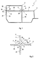
- FIG. 1 shows the cross section of a composite profile 1, which is composed of a first metal profile part 2 with a U-shaped cross-section and a second, designed as a hollow profile with two chambers metal profile part 3. Both metal profile parts 2 and 3 are made of an aluminum extruded profile.
- the first U-shaped metal profile part 2 stands with its two legs 4 and 5 so dull on an outer surface 6 of the second metal profile part 3, that the leg 4 with the outer surface 21 having wall 23 of the second metal profile part 3 and the other leg 5 with an intermediate wall 24 of the second metal profile part 3 is aligned, said intermediate wall separating the two chambers of the second metal profile part 3.
- the other leg 5 of the first metal profile part 2 forms with a extending over both chambers wall 25 of the second metal profile part 3 a T-joint 7, wherein outside of the area of this T-joint 7 of the corresponding throat area 8 is located.
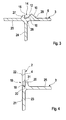
- This T-joint 7 with the throat area 8 is based on the Figures 2 and 3 that provide a more detailed section A according to FIG. 1 show, explained.
- FIG. 3 is in a node 26 of the second metal profile part 3, a connecting groove 14 integrally formed with a substantially on the outer surface 6 perpendicular inner groove wall 15, a groove bottom 16 and an outer groove wall 12.
- the inner groove wall 15 is formed by a protruding cross-section trapezoidal nose 27.
- the outer groove wall 12 is inclined outwards at an angle of approximately 45 ° and represents a surface of a nose 10 with a triangular cross section, wherein the second surface 29 of this nose 10 is inclined at an angle of approximately 45 ° relative to the surface 6.
- the free end of the leg 5 fits with its end face 17 fit into this connection groove 14 a.
- a nose 9 is formed with triangular cross-section forming surfaces 11 and 28 at this free end of the leg 5, so that the surface 11 of this nose 9 to form a weld joint 13 on the surface 12 of the arranged on the surface 6 nose 10th is applied.
- the two other surfaces 28 and 29 of the lugs 9 and 10 together form a flat surface.
- the weld joint 13 extends substantially in the diagonal of the throat area 8.
- This weld joint 13 serves to connect the two metal profile parts 2 and 3 by friction stir welding by producing a fillet weld.
- a rotating pin which protrudes from a cylindrical shoulder of a tool, pressed with great force in this weld joint 13 until the tool shoulder rests on the surface formed by the two lugs 9 and 10.
- the tool is moved along the joint line, wherein the material is heated by the friction between the tool shoulder and the lugs 9 and 10 and stirred by the rotation of the pin, so that at the weld joint 13 of the legs 5 with the wall 25 in a Hot forming process to form a fillet weld connects.
- the still missing welding of the other leg 4 of the first metal profile part 2 with the second metal profile part 3 via the already mentioned above further welding joint 18 can be carried out simultaneously with the welding of the weld joint 13 or after its welding. Also this welding of the other Welding joint 18 is preferably carried out by means of the already described friction stir welding.
- a stepped shoulder 20 with an undercut on its step surface 31 is formed on an edge 19 of the second metal profile part 3 against which the leg 4 abuts, such that the end of the leg 4 engages positively in the shoulder 20 and
- the surfaces 22 and 21 of the leg 4 or of the wall 23 adjoining the weld joint 18 form a flat surface.
- the undercut extending the weld joint 18 forming surface-locking abutting surfaces 30 and 31 are not in the plane of the wall 25, that is perpendicular to the outer surfaces 21 and 22, but inclined inwards.
- the surface 30, the end face of the free leg 4 and the surface 31, the step surface of the paragraph 20 represents.
Landscapes
- Engineering & Computer Science (AREA)
- Mechanical Engineering (AREA)
- Chemical & Material Sciences (AREA)
- Combustion & Propulsion (AREA)
- Transportation (AREA)
- Architecture (AREA)
- Structural Engineering (AREA)
- Pressure Welding/Diffusion-Bonding (AREA)
- Arc Welding In General (AREA)
- Butt Welding And Welding Of Specific Article (AREA)
Abstract
Description
- Die Erfindung betrifft ein Verbundprofil bestehend aus wenigstens einem ersten und zweiten Metallprofilteil gemäß Oberbegriff des Patentanspruchs 1 sowie dessen Verwendung als Karosseriebauteil im Fahrzeugbau.
- Aus der
DE 10 2007 018 459 A1 ist ein solches Verbundprofil zur Verwendung als Karosseriebauteil für ein Kraftfahrzeug bekannt. Dieses Verbundprofil besteht aus einem im Querschnitt U-förmigen Profilteil, das als Einzelbauelement über seine beiden freien Schenkel mit einem weiteren als Hohlprofil mit mehreren Kammern ausgebildeten Bauteil verbunden wird. In Querrichtung der beiden zu verbindenden Profilteile weisen diese übereinstimmende Abmessungen auf, so dass über stufige Absätze diese Bauteile derart unter Ausbildung von Schweißstößen zusammengesteckt werden können, dass die aneinanderstoßenden Flächen miteinander fluchten. Die Verbindung erfolgt dann bspw. über eine Schweißverbindung, insbesondere durch Rührreibschweißen. - Im Karosseriebau für Kraftfahrzeuge werden zunehmend im Querschnitt relativ große Hohlprofile eingesetzt, die bspw. aus Aluminium-Strangpressprofilen hergestellt werden. Bei Strangpressprofilen gibt es seitens der Fertigungstechnik eine Abhängigkeit der minimal pressbaren Wandstärke zur Größe es Profilquerschnitts, d. h. die Wanddicke der einzelnen Innen- oder Außenwände des Strangpressprofils wird umso größer, je größer der Querschnitt des Hohlprofils sein soll.
- Es ist bekannt, dünnwandige Profilteile mit großem Querschnitt dadurch herzustellen, indem Profilteile mit kleinen Querschnitten zusammengesetzt werden. Ein solches Vorgehen ist bspw. aus der
DE 10 2007 458 A1 bekannt, bei dem Einzelstrangpressprofile über stumpf aufeinander stoßende Verbindungsstellen miteinander bspw. mittels Rührreibschweißen verschweißt werden. - Aufgabe der Erfindung ist es, ein Verbundprofil bestehend aus wenigstens einem ersten und zweiten Metallprofilteil der eingangs genannten Art anzugeben, das gegenüber dem Stand der Technik verbesserte Eigenschaften aufweist.
- Diese Aufgabe wird gelöst durch ein Verbundprofil mit den Merkmalen des Patentanspruchs 1.
- Bei einem solchen Verbundprofil, bestehend aus wenigstens einem ersten und zweiten Metallprofilteil, wobei das erste Metallprofilteil mit zwei parallelen Schenkeln einen U-förmigen Teilquerschnitt aufweist und über diese Schenkel mittels Schweißen mit dem zweiten Metallprofilteil verbunden wird, ist erfindungsgemäß vorgesehen, dass
- wenigstens ein Schenkel des ersten Metallprofilteils mit einer Außenfläche des zweiten Metallprofilteils einen T-Stoß bildet, und
- im Kehlbereich des T-Stoßes eine im Querschnitt im Wesentlichen dreiecksförmige Nase sowohl am Rand des einen Schenkels des ersten Metallprofilteils als auch auf der Außenfläche des zweiten Metallprofilteils derart angeformt ist, dass die Nasen mit jeweils einer ihrer Flächen flächig unter Ausbildung eines Schweißstoßes aneinander liegend zusammen einen dreiecksförmigen Querschnitt bilden.
- Mit dieser erfindungsgemäßen Gestaltung der des ersten und zweiten Metallprofilteils kann im Kehlbereich des T-Stoßes eine Kehlnaht mittels Schweißen zur Verbindung der beiden Bauteile eingebracht werden, die ohne eine Stützrippe zur Abstützung der Schweißkraft auskommt, insbesondere bei Verwendung von Rührreibschweißen, das im Vergleich zu anderen Schweißverfahren zu einem geringeren Wärmeeintrag führt und bereits dadurch ein geringer Verzug vorhanden ist.
- Bei einer vorteilhaften Weiterbildung der Erfindung sind die beiden Nasen derart ausgebildet sind, dass der Schweißstoß im Wesentlichen auf der Diagonalen des Kehlbereichs verläuft. Damit wird eine optimale Zugänglichkeit durch das Schweißwerkzeug, insbesondere durch ein Werkzeug für Rührreibschweißen sichergestellt.
- Besonders vorteilhaft ist, wenn gemäß einer vorteilhaften Weiterbildung der Erfindung im Bereich des T-Stoßes das zweite Metallprofilteil zur Verbindung mit dem ersten Metallprofilteil eine Verbindungsnut mit einer im Wesentlichen senkrecht auf der Außenfläche stehenden inneren Nutwand und einer von der den Schweißstoß bildenden Fläche gebildeten äußeren Nutwand aufweist, wobei der Nutgrund an die Stirnfläche des einen Schenkels angepasst ist. Mit einer solchen Verbindungsnut kann das erste Metallprofilteil an dem zweiten Metallprofilteil vor dem Schweißen fixiert werden.
- Bei einer anderen Weiterbildung der Erfindung liegt zur Ausbildung eines weiteren Schweißstoßes der weitere Schenkel des ersten Metallprofilteils flächenbündig an den Flächen eines an einer Kante des zweiten Metallprofilteils angeformten stufigen Absatzes flächenbündig an, wobei vorzugsweise der stufige Absatz derart ausgebildet ist, dass die an dem Schweißstoß angrenzenden Außenflächen des ersten und zweiten Metallprofilteils miteinander fluchten.
- Besonders vorteilhaft hinsichtlich des weiteren Schweißstoßes ist es dabei, dass zur Bildung des Schweißstoßes eine Stirnfläche des Schenkels flächenbündig an einer Stufenfläche des Absatzes anliegt und dabei die Stirnfläche und die Stufenfläche hinsichtlich der angrenzenden Außenflächen derart geneigt verlaufen, dass an der Stufenfläche des Absatzes ein Hinterschnitt entsteht.
- In vorteilhafter Weise ist das zweite Metallprofilteil als Hohlprofil mit mehreren Kammern ausgebildet.
- Das erste Metallprofilteil kann als U-förmiges Profilteil ausgebildet werden. Daneben ist es auch möglich, dass der U-förmige Teilquerschnitt des ersten Metallprofilteil Teil eines Querschnittes eines Hohlprofils mit wenigsten einer Kammer ist.
- Gemäß einer Weiterbildung der Erfindung ist das erste und zweite Metallprofilteil aus einem Strangpressprofil gebildet.
- Zur Verbindung des ersten Metallprofilteil mit dem zweiten Metallprofilteil wird bevorzugt Rührreibschweißen vorgeschlagen, das vorteilhaft aufgrund des geringen Wärmeeintrags zu einem geringen Verzug und damit zu guten Materialeigenschaften führt.
- In vorteilhafter Weise wird das erfindungsgemäße Verbundprofil zur Herstellung von Karosseriebauteilen im Kraftfahrzeugbau verwendet.
- Die Erfindung wird nachfolgend anhand eines Ausführungsbeispiels unter Bezugnahme auf die beigefügten Figuren ausführlich beschrieben. Es zeigen:
- Figur 1
- eine Querschnittsdarstellung eines Ausführungsbeispiels eines erfindungsgemäßen Verbundprofils,
- Figur 2
- eine vergrößerte Darstellung des Details A nach
Figur 1 , - Figur 3
- eine vergrößerte Darstellung des zweiten Metallprofilteils 3 nach
Figur 2 , und - Figur 4
- eine vergrößerte Darstellung des Details B nach
Figur 1 . -
Figur 1 zeigt den Querschnitt eines Verbundprofils 1, das aus einem ersten Metallprofilteil 2 mit U-förmigen Querschnitt und einem zweiten, als Hohlprofil mit zwei Kammern ausgebildeten Metallprofilteil 3 aufgebaut ist. Beide Metallprofilteile 2 und 3 sind aus einem Aluminium-Strangpressprofil hergestellt. - Das erste U-förmige Metallprofilteil 2 steht mit seinen beiden Schenkeln 4 und 5 derart stumpf auf einer Außenfläche 6 des zweiten Metallprofilteils 3, dass der Schenkel 4 mit der die Außenfläche 21 aufweisende Wand 23 des zweiten Metallprofilteils 3 und der weitere Schenkel 5 mit einer Zwischenwand 24 des zweiten Metallprofilteils 3 fluchtet, wobei diese Zwischenwand die beiden Kammern des zweiten Metallprofilteils 3 trennt.
- Eine Außenfläche 22 des Schenkels 4 bildet damit mit der Außenfläche 21 eine ebene Oberfläche. Die Verbindung dieses Schenkels 4 mit dem zweiten Metallprofilteil 3 über einen Schweißstoß 18 wird als Detail B weiter unten erläutert.
- Der andere Schenkel 5 des ersten Metallprofilteils 2 bildet mit einer über beide Kammern verlaufenden Wand 25 des zweiten Metallprofilteils 3 einen T-Stoß 7, wobei sich außen im Bereich dieses T-Stoßes 7 der zugehörige Kehlbereich 8 befindet.
- Dieser T-Stoß 7 mit dem Kehlbereich 8 wird anhand der
Figuren 2 und3 , die einen detaillierteren Ausschnitt A gemäßFigur 1 zeigen, erläutert. - Gemäß
Figur 3 ist in einem Knoten 26 des zweiten Metallprofilteils 3 eine Verbindungsnut 14 mit einer im Wesentlichen auf der Außenfläche 6 senkrecht stehenden inneren Nutwand 15, einem Nutgrund 16 und einer äußeren Nutwand 12 angeformt. Die innere Nutwand 15 wird von einer überstehenden im Querschnitt trapezförmigen Nase 27 gebildet. Die äußere Nutwand 12 steht nach außen geneigt mit einem Winkel von ca. 45° und stellt eine Fläche einer Nase 10 mit dreiecksförmigen Querschnitt dar, wobei auch die zweite Fläche 29 dieser Nase 10 unter einem Winkel von ca. 45° gegenüber der Oberfläche 6 geneigt ist. - Wie
Figur 1 und insbesondereFigur 2 zeigt, fügt sich das freie Ende des Schenkels 5 mit seiner Stirnfläche 17 passgenau in diese Verbindungnut 14 ein. Hierzu ist auch an diesem freien Ende des Schenkels 5 eine Nase 9 mit dreiecksförmigen Querschnitt unter Ausbildung von Flächen 11 und 28 angeformt, so dass die Fläche 11 dieser Nase 9 unter Ausbildung einer Schweißstoßes 13 an der Fläche 12 der auf der Oberfläche 6 angeordneten Nase 10 anliegt. Die beiden anderen Flächen 28 und 29 der Nasen 9 und 10 bilden gemeinsam eine ebene Oberfläche. Damit verläuft der Schweißstoß 13 im Wesentlichen in der Diagonale des Kehlbereichs 8. - Dieser Schweißstoß 13 dient dazu, die beiden Metallprofilteile 2 und 3 durch eine Rührreibschweißung durch Erzeugen einer Kehlnaht miteinander zu verbinden. Hierbei wird ein rotierende Stift, der aus einer zylindrischen Schulter eines Werkzeugs herausragt, mit großer Kraft in diesen Schweißstoß 13 gedrückt, bis die Werkzeugschulter auf der von den beiden Nasen 9 und 10 gebildeten Oberfläche aufliegt. Das Werkzeug wird entlang der Fügelinie bewegt, wobei sich durch die Reibung zwischen der Werkzeugschulter und den Nasen 9 und 10 das Material erwärmt und durch die Rotation des Stiftes verrührt wird, so dass sich an dem Schweißstoß 13 der Schenkel 5 mit der Wand 25 in einem Warmumformprozess unter Bildung einer Kehlnaht verbindet.
- Da einer der Vorteile dieses Schweißverfahrens darin besteht, dass im Vergleich zu anderen Schweißverfahren nur ein geringer Wärmeeintrag erfolgt und damit auch nur ein geringer Verzug sich einstellt, kann aufgrund der erfindungsgemäßen Geometrie der beiden Metallprofilteile 2 und 3 in dem T-Stoß 7 auf eine sonst erforderliche Abstützrippe verzichtet werden.
- Die noch fehlende Verschweißung des anderen Schenkels 4 des ersten Metallprofilteils 2 mit dem zweiten Metallprofilteil 3 über den bereits oben erwähnten weiteren Schweißstoß 18 kann gleichzeitig mit dem Verschweißen des Schweißstoßes 13 oder nach dessen Verschweißung durchgeführt werden. Auch diese Verschweißung des weiteren Schweißstoßes 18 erfolgt vorzugsweise mittels des bereits erläuterten Rührreibschweißens.
- Zur Ausbildung des weiteren Schweißstoßes 18 ist an einer Kante 19 des zweiten Metallprofilteils 3, an der der Schenkel 4 anliegt, ein gestufter Absatz 20 mit einer Hinterschneidung an dessen Stufenfläche 31 derart ausgebildet, dass das Ende des Schenkels 4 formschlüssig in den Absatz 20 eingreift und dabei die an den Schweißstoß 18 angrenzenden Flächen 22 bzw. 21 des Schenkels 4 bzw. der Wand 23 eine ebene Oberfläche bilden. Zur Bildung der Hinterschneidung verlaufen die den Schweißstoß 18 bildenden flächenschlüssig aneinander liegenden Flächen 30 und 31 nicht in der Ebene der Wand 25, also senkrecht zu den Außenflächen 21 und 22, sondern nach innen geneigt. Dabei stellt die Fläche 30 die Stirnfläche des freien Schenkels 4 und die Fläche 31 die Stufenfläche des Absatzes 20 dar.
- Natürlich kann anstelle des U-förmigen ersten Metallprofilteils 2 ein Hohlprofil mit einem U-förmigen Teilquerschnitt eingesetzt werden. Ferner können durch entsprechende Ausbildung der Kontaktstellen mehrere solcher ersten Metallprofilteile mit dem ersten Metallprofilteil verbunden werden. Schließlich ist es auch möglich, in entsprechender Weise ein drittes Metallprofilteil mit dem zweiten Metallprofilteil zu verbinden, so dass das entstehende Verbundprofil aus drei Metallprofilteilen besteht.
- Bezugszeichen
- 1
- Verbundprofil
- 2
- erstes Metallprofilteil
- 3
- zweites Metallprofilteil
- 4
- Schenkel des ersten Metallprofilteils 2
- 5
- Schenkel des ersten Metallprofilteils 2
- 6
- Außenfläche des zweiten Metallprofilteils 3
- 7
- T-Stoß
- 8
- Kehlbereich im T-Stoß 7
- 9
- dreiecksförmige Nase am Schenkel 5
- 10
- dreiecksförmige Nase auf der Außenfläche 6
- 11
- Fläche an der Nase 9
- 12
- Fläche an der Nase 10
- 13
- Schweißstoß
- 14
- Verbindungsnut von Metallprofilteil 3
- 15
- innere Nutwand von Verbindungsnut 14
- 16
- Nutgrund von Verbindungsnut 14
- 17
- Stirnfläche des Schenkels 5
- 18
- weiterer Schweißstoß
- 19
- Kante an dem zweiten Metallprofilteil 3
- 20
- stufiger Absatz an der Kante 19
- 21
- Außenfläche am zweiten Metallprofilteil 3
- 22
- Außenfläche am ersten Metallprofilteil 2
- 23
- Wand des zweiten Metallprofilteils 3
- 24
- Zwischenwand des zweiten Metallprofilteils 3
- 25
- Wand des zweiten Metallprofilteils 3
- 26
- Knoten des zweiten Metallprofilteils 3
- 27
- Nase
- 28
- weitere Fläche an der Nase 9
- 29
- weitere Fläche an der Nase 10
- 30
- Stirnfläche des Schenkels 4
- 31
- Stufenfläche des Absatzes 20
Claims (12)
- Verbundprofil (1) bestehend aus wenigstens einem ersten und zweiten Metallprofilteil (2, 3), wobei das erste Metallprofilteil (2) mit zwei parallelen Schenkeln (4, 5) einen U-förmigen Teilquerschnitt aufweist und über diese Schenkel (4, 5) mittels Schweißen mit dem zweiten Metallprofilteil (3) verbunden wird,
dadurch gekennzeichnet, dass- wenigstens ein Schenkel (5) des ersten Metallprofilteils (2) mit einer Außenfläche (6) des zweiten Metallprofilteils (3) einen T-Stoß (7) bildet, und- im Kehlbereich (8) des T-Stoßes (7) eine im Querschnitt im Wesentlichen dreiecksförmige Nase (9, 10) sowohl am Rand des einen Schenkels (5) des ersten Metallprofilteils (2) als auch auf der Außenfläche (6) des zweiten Metallprofilteils (3) derart angeformt ist, dass die Nasen (9, 10) mit jeweils einer ihrer Flächen (11, 12) flächig unter Ausbildung eines Schweißstoßes (13) aneinander liegend zusammen einen dreiecksförmigen Querschnitt bilden. - Verbundprofil nach Anspruch 1,
dadurch gekennzeichnet, dass die beiden Nasen (9, 10) derart ausgebildet sind, dass der Schweißstoß (13) im Wesentlichen auf der Diagonalen des Kehlbereichs (8) verläuft. - Verbundprofil nach Anspruch 1 oder 2,
dadurch gekennzeichnet, dass im Bereich des T-Stoßes (7) das zweite Metallprofilteil (3) zur Verbindung mit dem ersten Metallprofilteil (2) eine Verbindungsnut (14) mit einer im Wesentlichen senkrecht auf der Außenfläche (6) stehenden inneren Nutwand (15) und einer von der den Schweißstoß (13) bildenden Fläche (12) gebildeten äußeren Nutwand aufweist, wobei der Nutgrund (16) an die Stirnfläche (17) des einen Schenkels (5) angepasst ist. - Verbundprofil nach einem der vorhergehenden Ansprüche,
dadurch gekennzeichnet, dass zur Ausbildung eines weiteren Schweißstoßes (18) der weitere Schenkel (4) des ersten Metallprofilteils (2) an den Flächen eines an einer Kante (19) des zweiten Metallprofilteils (3) angeformten stufigen Absatzes (20) flächenbündig anliegt. - Verbundprofil nach Anspruch 4,
dadurch gekennzeichnet, dass zur Bildung des Schweißstoßes (18) eine Stirnfläche (30) des Schenkels (4) flächenbündig an einer Stufenfläche (31) des Absatzes (20) anliegt und die Stirnfläche (30) und die Stufenfläche (31) hinsichtlich der angrenzenden Außenflächen (21, 22) derart geneigt verlaufen, dass an der Stufenfläche (31) des Absatzes (20) ein Hinterschnitt entsteht. - Verbundprofil nach Anspruch 4 oder 5,
dadurch gekennzeichnet, dass der stufige Absatz (20) derart ausgebildet ist, dass die an dem Schweißstoß (18) angrenzenden Außenflächen (21, 22) des ersten und zweiten Metallprofilteils (2, 3) miteinander fluchten. - Verbundprofil nach einem der vorhergehenden Ansprüche,
dadurch gekennzeichnet, dass das zweite Metallprofilteil (3) als Hohlprofil mit mehreren Kammern ausgebildet ist. - Verbundprofil nach einem der vorhergehenden Ansprüche,
dadurch gekennzeichnet, dass das das erste Metallprofilteil als U-förmiges Profilteil (2) ausgebildet ist. - Verbundprofil nach einem der Ansprüche 1 bis 7,
dadurch gekennzeichnet, dass der U-förmige Teilquerschnitt des ersten Metallprofilteils (1) Teil eines Querschnittes eines Hohlprofils mit wenigsten einer Kammer ist. - Verbundprofil nach einem der vorhergehenden Ansprüche,
dadurch gekennzeichnet, dass das erste und zweite Metallprofilteil (2, 3) aus einem Strangpressprofil gebildet sind. - Verbundprofil nach einem der vorhergehenden Ansprüche,
dadurch gekennzeichnet, dass das erste Metallprofilteil (2) mit dem zweiten Metallprofilteil (3) durch eine Rührreibschweißverbindung verbunden wird. - Verwendung des Verbundprofils nach einem der vorhergehenden Ansprüche für ein Karosseriebauteil eines Kraftfahrzeugs.
Applications Claiming Priority (1)
| Application Number | Priority Date | Filing Date | Title |
|---|---|---|---|
| DE102009050775A DE102009050775B4 (de) | 2009-10-27 | 2009-10-27 | Verbundprofil bestehend aus wenigstens einem ersten und zweiten Metallprofilteil |
Publications (2)
| Publication Number | Publication Date |
|---|---|
| EP2316712A1 true EP2316712A1 (de) | 2011-05-04 |
| EP2316712B1 EP2316712B1 (de) | 2012-05-09 |
Family
ID=43432220
Family Applications (1)
| Application Number | Title | Priority Date | Filing Date |
|---|---|---|---|
| EP10013838A Active EP2316712B1 (de) | 2009-10-27 | 2010-10-21 | Verbundprofil bestehend aus wenigstens einem ersten und zweiten Metallprofilteil |
Country Status (4)
| Country | Link |
|---|---|
| EP (1) | EP2316712B1 (de) |
| AT (1) | ATE556921T1 (de) |
| DE (1) | DE102009050775B4 (de) |
| ES (1) | ES2387739T3 (de) |
Families Citing this family (1)
| Publication number | Priority date | Publication date | Assignee | Title |
|---|---|---|---|---|
| DE102015103226B4 (de) | 2015-03-05 | 2023-07-06 | Dr. Ing. H.C. F. Porsche Aktiengesellschaft | Längsträger für ein Kraftfahrzeug |
Citations (6)
| Publication number | Priority date | Publication date | Assignee | Title |
|---|---|---|---|---|
| WO1992014006A1 (en) * | 1991-01-31 | 1992-08-20 | Norsk Hydro A.S | Method of joining structural members, profile member and structural unit comprising a plurality of profile members |
| US5271687A (en) * | 1992-04-03 | 1993-12-21 | Ford Motor Company | Space frame joint construction |
| DE19609722A1 (de) * | 1996-03-13 | 1997-09-18 | Blz Gmbh | Verfahren zum Verbinden zweier metallischer Profile, insbesondere zweier stranggepreßter Aluminiumprofilteile |
| US20040004109A1 (en) * | 1997-07-23 | 2004-01-08 | Kinya Aota | Friction stir welding method, frame members used therein, and product formed thereby |
| DE102007018459A1 (de) | 2007-04-19 | 2008-10-23 | Audi Ag | Karosseriebauteil für einen Kraftwagen |
| DE102007018458A1 (de) | 2007-04-19 | 2008-11-06 | Audi Ag | Karosseriebauteil für einen Kraftwagen und Verfahren zu dessen Herstellung |
Family Cites Families (7)
| Publication number | Priority date | Publication date | Assignee | Title |
|---|---|---|---|---|
| DE2608107C3 (de) * | 1976-02-27 | 1982-02-11 | Sumitomo Metal Industries, Ltd., Osaka | Verfahren und Einrichtung zum maschinellen Lichtbogenschweißen waagerechter Kehlnähte |
| DE2759836C2 (de) * | 1976-08-27 | 1983-05-05 | Mitsubishi Denki K.K., Tokyo | Verfahren zum Lichtbogen-Verbindungsschweißen |
| DE2829343A1 (de) * | 1977-07-06 | 1979-01-25 | Vmw Ranshofen Berndorf Ag | Gelochte und mit erhebungen gegen ausrutschen versehene bodenelemente aus abgekantetem blech oder u-foermigen profilen |
| DE4216643A1 (de) * | 1992-05-20 | 1993-11-25 | Fraunhofer Ges Forschung | Verfahren und Vorrichtung zum Schweißen mit mehreren Hochenergie-Schweißstrahlen |
| DE4316165C1 (de) * | 1993-05-14 | 1994-03-10 | Benteler Werke Ag | Verfahren zur Erzeugung der Schweißstoßflächen von tiefgezogenen Blechschalen, Vorrichtung zur Durchführung des Verfahrens und Blechschale |
| DE10207458A1 (de) | 2002-01-22 | 2003-07-31 | Opel Adam Ag | Hubkolben-Brennkraftmaschine in Reihenbauart mit Massenausgleichswellen |
| DE102005048001B4 (de) * | 2005-10-06 | 2007-06-14 | Euro-Composites S.A., Zone Industrielle | Verbindungselement |
-
2009
- 2009-10-27 DE DE102009050775A patent/DE102009050775B4/de not_active Withdrawn - After Issue
-
2010
- 2010-10-21 EP EP10013838A patent/EP2316712B1/de active Active
- 2010-10-21 ES ES10013838T patent/ES2387739T3/es active Active
- 2010-10-21 AT AT10013838T patent/ATE556921T1/de active
Patent Citations (6)
| Publication number | Priority date | Publication date | Assignee | Title |
|---|---|---|---|---|
| WO1992014006A1 (en) * | 1991-01-31 | 1992-08-20 | Norsk Hydro A.S | Method of joining structural members, profile member and structural unit comprising a plurality of profile members |
| US5271687A (en) * | 1992-04-03 | 1993-12-21 | Ford Motor Company | Space frame joint construction |
| DE19609722A1 (de) * | 1996-03-13 | 1997-09-18 | Blz Gmbh | Verfahren zum Verbinden zweier metallischer Profile, insbesondere zweier stranggepreßter Aluminiumprofilteile |
| US20040004109A1 (en) * | 1997-07-23 | 2004-01-08 | Kinya Aota | Friction stir welding method, frame members used therein, and product formed thereby |
| DE102007018459A1 (de) | 2007-04-19 | 2008-10-23 | Audi Ag | Karosseriebauteil für einen Kraftwagen |
| DE102007018458A1 (de) | 2007-04-19 | 2008-11-06 | Audi Ag | Karosseriebauteil für einen Kraftwagen und Verfahren zu dessen Herstellung |
Also Published As
| Publication number | Publication date |
|---|---|
| DE102009050775A1 (de) | 2011-04-28 |
| DE102009050775B4 (de) | 2012-06-06 |
| ES2387739T3 (es) | 2012-10-01 |
| EP2316712B1 (de) | 2012-05-09 |
| ATE556921T1 (de) | 2012-05-15 |
Similar Documents
| Publication | Publication Date | Title |
|---|---|---|
| DE102008038276B4 (de) | Verfahren zur Verbindung von Fahrwerksteilen und Fahrwerksbaugruppe | |
| DE69929854T2 (de) | Hohlförmiges extrudiertes Rahmenprofil und Aufbaustruktur | |
| DE102007047036A1 (de) | Verfahren zur Herstellung eines weitestgehend flächenförmigen Bauteileverbundes und weitestgehend flächenförmiger Bauteileverbund dazu | |
| DE102016113357A1 (de) | Verbindungsverfahren für Blechwerkstoffe und Fahrzeugkarosserie oder -fahrwerk | |
| DE102014113403A1 (de) | Aufbau eines Seitenschwellers und Verfahren zum Aufbauen einer Fahrzeugkarosserie | |
| DE102012022876A1 (de) | Verstärkungselement zur Verstärkung eines Hohlprofils sowie Hohlprofil mit einem solchen Verstärkungselement | |
| EP2792445B1 (de) | Hohlprofilverbindung unter Verwendung des Reibrührschweissens | |
| EP2316712B1 (de) | Verbundprofil bestehend aus wenigstens einem ersten und zweiten Metallprofilteil | |
| DE102010044902B4 (de) | Verfahren zum Einbringen einer Gewindehülse in ein Werkstück und Fügeverbindung zwischen Gewindehülse und Werkstück | |
| DE102008054159B4 (de) | Verfahren zum Herstellen einer Klemmleiste | |
| DE102015001151A1 (de) | Verfahren zum Herstellen einer Schweißverbindung | |
| EP4371857B1 (de) | Kraftfahrzeugbauteil umfassend zwei profile | |
| WO2017093297A1 (de) | Hohlkammerprofil | |
| EP1556185A1 (de) | Verfahren zur herstellung eines spurstangengehäuses | |
| EP2977119A2 (de) | Verfahren zum herstellen eines torsionsprofils aus einer platine sowie torsionsprofil | |
| AT519328B1 (de) | Trägeranordnung für einen Wagenkasten eines Fahrzeugs | |
| EP2030825B1 (de) | Verfahren zum Herstellen einer Klemmleiste | |
| DE102007018458A1 (de) | Karosseriebauteil für einen Kraftwagen und Verfahren zu dessen Herstellung | |
| DE102014101757A1 (de) | Hohlprofilbauteil mit Flansch | |
| DE102014206196A1 (de) | Dachrahmen für eine Fahrzeugkarosserie | |
| EP3960319A1 (de) | Verfahren zum kalibrieren eines metallischen profilrohlings mit wenigstens einer massiven wand | |
| EP2792446B1 (de) | Hohlprofilverbindung unter Anwendung des Reibrührschweissens | |
| DE102014001230B4 (de) | Langgestreckter Karosserieträger einer Fahrzeugkarosserie | |
| WO2020126507A1 (de) | Verfahren zur herstellung eines schienenfahrzeugwagenkastens | |
| WO2006002447A1 (de) | Verfahren zum herstellen eines wagenkastens eines schienenfahrzeuges |
Legal Events
| Date | Code | Title | Description |
|---|---|---|---|
| PUAI | Public reference made under article 153(3) epc to a published international application that has entered the european phase |
Free format text: ORIGINAL CODE: 0009012 |
|
| AK | Designated contracting states |
Kind code of ref document: A1 Designated state(s): AL AT BE BG CH CY CZ DE DK EE ES FI FR GB GR HR HU IE IS IT LI LT LU LV MC MK MT NL NO PL PT RO RS SE SI SK SM TR |
|
| AX | Request for extension of the european patent |
Extension state: BA ME |
|
| 17P | Request for examination filed |
Effective date: 20111104 |
|
| GRAP | Despatch of communication of intention to grant a patent |
Free format text: ORIGINAL CODE: EPIDOSNIGR1 |
|
| RIC1 | Information provided on ipc code assigned before grant |
Ipc: B62D 29/00 20060101AFI20111212BHEP |
|
| RIN1 | Information on inventor provided before grant (corrected) |
Inventor name: SANDER, JUERGEN Inventor name: GRASL, WOLFGANG Inventor name: ELLERMANN, FRANK Inventor name: GOTTHELF, MATTHIAS Inventor name: KEITH, TORSTEN Inventor name: HOFFMANN, ALEXANDER |
|
| GRAS | Grant fee paid |
Free format text: ORIGINAL CODE: EPIDOSNIGR3 |
|
| GRAA | (expected) grant |
Free format text: ORIGINAL CODE: 0009210 |
|
| AK | Designated contracting states |
Kind code of ref document: B1 Designated state(s): AL AT BE BG CH CY CZ DE DK EE ES FI FR GB GR HR HU IE IS IT LI LT LU LV MC MK MT NL NO PL PT RO RS SE SI SK SM TR |
|
| REG | Reference to a national code |
Ref country code: GB Ref legal event code: FG4D Free format text: NOT ENGLISH |
|
| REG | Reference to a national code |
Ref country code: AT Ref legal event code: REF Ref document number: 556921 Country of ref document: AT Kind code of ref document: T Effective date: 20120515 Ref country code: CH Ref legal event code: EP |
|
| REG | Reference to a national code |
Ref country code: SE Ref legal event code: TRGR |
|
| REG | Reference to a national code |
Ref country code: IE Ref legal event code: FG4D Free format text: LANGUAGE OF EP DOCUMENT: GERMAN |
|
| REG | Reference to a national code |
Ref country code: DE Ref legal event code: R096 Ref document number: 502010000651 Country of ref document: DE Effective date: 20120719 |
|
| REG | Reference to a national code |
Ref country code: NL Ref legal event code: VDEP Effective date: 20120509 |
|
| REG | Reference to a national code |
Ref country code: ES Ref legal event code: FG2A Ref document number: 2387739 Country of ref document: ES Kind code of ref document: T3 Effective date: 20121001 |
|
| REG | Reference to a national code |
Ref country code: LT Ref legal event code: MG4D Effective date: 20120509 |
|
| PG25 | Lapsed in a contracting state [announced via postgrant information from national office to epo] |
Ref country code: LT Free format text: LAPSE BECAUSE OF FAILURE TO SUBMIT A TRANSLATION OF THE DESCRIPTION OR TO PAY THE FEE WITHIN THE PRESCRIBED TIME-LIMIT Effective date: 20120509 Ref country code: PL Free format text: LAPSE BECAUSE OF FAILURE TO SUBMIT A TRANSLATION OF THE DESCRIPTION OR TO PAY THE FEE WITHIN THE PRESCRIBED TIME-LIMIT Effective date: 20120509 Ref country code: CY Free format text: LAPSE BECAUSE OF FAILURE TO SUBMIT A TRANSLATION OF THE DESCRIPTION OR TO PAY THE FEE WITHIN THE PRESCRIBED TIME-LIMIT Effective date: 20120509 Ref country code: FI Free format text: LAPSE BECAUSE OF FAILURE TO SUBMIT A TRANSLATION OF THE DESCRIPTION OR TO PAY THE FEE WITHIN THE PRESCRIBED TIME-LIMIT Effective date: 20120509 Ref country code: RS Free format text: LAPSE BECAUSE OF FAILURE TO SUBMIT A TRANSLATION OF THE DESCRIPTION OR TO PAY THE FEE WITHIN THE PRESCRIBED TIME-LIMIT Effective date: 20120509 Ref country code: NO Free format text: LAPSE BECAUSE OF FAILURE TO SUBMIT A TRANSLATION OF THE DESCRIPTION OR TO PAY THE FEE WITHIN THE PRESCRIBED TIME-LIMIT Effective date: 20120809 Ref country code: IS Free format text: LAPSE BECAUSE OF FAILURE TO SUBMIT A TRANSLATION OF THE DESCRIPTION OR TO PAY THE FEE WITHIN THE PRESCRIBED TIME-LIMIT Effective date: 20120909 |
|
| PG25 | Lapsed in a contracting state [announced via postgrant information from national office to epo] |
Ref country code: GR Free format text: LAPSE BECAUSE OF FAILURE TO SUBMIT A TRANSLATION OF THE DESCRIPTION OR TO PAY THE FEE WITHIN THE PRESCRIBED TIME-LIMIT Effective date: 20120810 Ref country code: SI Free format text: LAPSE BECAUSE OF FAILURE TO SUBMIT A TRANSLATION OF THE DESCRIPTION OR TO PAY THE FEE WITHIN THE PRESCRIBED TIME-LIMIT Effective date: 20120509 Ref country code: HR Free format text: LAPSE BECAUSE OF FAILURE TO SUBMIT A TRANSLATION OF THE DESCRIPTION OR TO PAY THE FEE WITHIN THE PRESCRIBED TIME-LIMIT Effective date: 20120509 Ref country code: LV Free format text: LAPSE BECAUSE OF FAILURE TO SUBMIT A TRANSLATION OF THE DESCRIPTION OR TO PAY THE FEE WITHIN THE PRESCRIBED TIME-LIMIT Effective date: 20120509 Ref country code: PT Free format text: LAPSE BECAUSE OF FAILURE TO SUBMIT A TRANSLATION OF THE DESCRIPTION OR TO PAY THE FEE WITHIN THE PRESCRIBED TIME-LIMIT Effective date: 20120910 |
|
| PG25 | Lapsed in a contracting state [announced via postgrant information from national office to epo] |
Ref country code: NL Free format text: LAPSE BECAUSE OF FAILURE TO SUBMIT A TRANSLATION OF THE DESCRIPTION OR TO PAY THE FEE WITHIN THE PRESCRIBED TIME-LIMIT Effective date: 20120509 Ref country code: CZ Free format text: LAPSE BECAUSE OF FAILURE TO SUBMIT A TRANSLATION OF THE DESCRIPTION OR TO PAY THE FEE WITHIN THE PRESCRIBED TIME-LIMIT Effective date: 20120509 Ref country code: RO Free format text: LAPSE BECAUSE OF FAILURE TO SUBMIT A TRANSLATION OF THE DESCRIPTION OR TO PAY THE FEE WITHIN THE PRESCRIBED TIME-LIMIT Effective date: 20120509 Ref country code: DK Free format text: LAPSE BECAUSE OF FAILURE TO SUBMIT A TRANSLATION OF THE DESCRIPTION OR TO PAY THE FEE WITHIN THE PRESCRIBED TIME-LIMIT Effective date: 20120509 Ref country code: EE Free format text: LAPSE BECAUSE OF FAILURE TO SUBMIT A TRANSLATION OF THE DESCRIPTION OR TO PAY THE FEE WITHIN THE PRESCRIBED TIME-LIMIT Effective date: 20120509 Ref country code: SK Free format text: LAPSE BECAUSE OF FAILURE TO SUBMIT A TRANSLATION OF THE DESCRIPTION OR TO PAY THE FEE WITHIN THE PRESCRIBED TIME-LIMIT Effective date: 20120509 |
|
| PLBE | No opposition filed within time limit |
Free format text: ORIGINAL CODE: 0009261 |
|
| STAA | Information on the status of an ep patent application or granted ep patent |
Free format text: STATUS: NO OPPOSITION FILED WITHIN TIME LIMIT |
|
| 26N | No opposition filed |
Effective date: 20130212 |
|
| BERE | Be: lapsed |
Owner name: AUDI A.G. Effective date: 20121031 |
|
| PG25 | Lapsed in a contracting state [announced via postgrant information from national office to epo] |
Ref country code: MC Free format text: LAPSE BECAUSE OF NON-PAYMENT OF DUE FEES Effective date: 20121031 |
|
| REG | Reference to a national code |
Ref country code: DE Ref legal event code: R097 Ref document number: 502010000651 Country of ref document: DE Effective date: 20130212 |
|
| REG | Reference to a national code |
Ref country code: IE Ref legal event code: MM4A |
|
| PG25 | Lapsed in a contracting state [announced via postgrant information from national office to epo] |
Ref country code: IE Free format text: LAPSE BECAUSE OF NON-PAYMENT OF DUE FEES Effective date: 20121021 Ref country code: BG Free format text: LAPSE BECAUSE OF FAILURE TO SUBMIT A TRANSLATION OF THE DESCRIPTION OR TO PAY THE FEE WITHIN THE PRESCRIBED TIME-LIMIT Effective date: 20120809 Ref country code: BE Free format text: LAPSE BECAUSE OF NON-PAYMENT OF DUE FEES Effective date: 20121031 |
|
| PG25 | Lapsed in a contracting state [announced via postgrant information from national office to epo] |
Ref country code: MT Free format text: LAPSE BECAUSE OF FAILURE TO SUBMIT A TRANSLATION OF THE DESCRIPTION OR TO PAY THE FEE WITHIN THE PRESCRIBED TIME-LIMIT Effective date: 20120509 Ref country code: AL Free format text: LAPSE BECAUSE OF FAILURE TO SUBMIT A TRANSLATION OF THE DESCRIPTION OR TO PAY THE FEE WITHIN THE PRESCRIBED TIME-LIMIT Effective date: 20120509 |
|
| PG25 | Lapsed in a contracting state [announced via postgrant information from national office to epo] |
Ref country code: TR Free format text: LAPSE BECAUSE OF FAILURE TO SUBMIT A TRANSLATION OF THE DESCRIPTION OR TO PAY THE FEE WITHIN THE PRESCRIBED TIME-LIMIT Effective date: 20120509 |
|
| PG25 | Lapsed in a contracting state [announced via postgrant information from national office to epo] |
Ref country code: SM Free format text: LAPSE BECAUSE OF FAILURE TO SUBMIT A TRANSLATION OF THE DESCRIPTION OR TO PAY THE FEE WITHIN THE PRESCRIBED TIME-LIMIT Effective date: 20120509 Ref country code: LU Free format text: LAPSE BECAUSE OF NON-PAYMENT OF DUE FEES Effective date: 20121021 |
|
| PG25 | Lapsed in a contracting state [announced via postgrant information from national office to epo] |
Ref country code: HU Free format text: LAPSE BECAUSE OF FAILURE TO SUBMIT A TRANSLATION OF THE DESCRIPTION OR TO PAY THE FEE WITHIN THE PRESCRIBED TIME-LIMIT Effective date: 20101021 |
|
| REG | Reference to a national code |
Ref country code: CH Ref legal event code: PL |
|
| PG25 | Lapsed in a contracting state [announced via postgrant information from national office to epo] |
Ref country code: CH Free format text: LAPSE BECAUSE OF NON-PAYMENT OF DUE FEES Effective date: 20141031 Ref country code: MK Free format text: LAPSE BECAUSE OF FAILURE TO SUBMIT A TRANSLATION OF THE DESCRIPTION OR TO PAY THE FEE WITHIN THE PRESCRIBED TIME-LIMIT Effective date: 20120509 Ref country code: LI Free format text: LAPSE BECAUSE OF NON-PAYMENT OF DUE FEES Effective date: 20141031 |
|
| REG | Reference to a national code |
Ref country code: FR Ref legal event code: PLFP Year of fee payment: 6 |
|
| REG | Reference to a national code |
Ref country code: FR Ref legal event code: PLFP Year of fee payment: 7 |
|
| REG | Reference to a national code |
Ref country code: AT Ref legal event code: MM01 Ref document number: 556921 Country of ref document: AT Kind code of ref document: T Effective date: 20151021 |
|
| PG25 | Lapsed in a contracting state [announced via postgrant information from national office to epo] |
Ref country code: AT Free format text: LAPSE BECAUSE OF NON-PAYMENT OF DUE FEES Effective date: 20151021 |
|
| REG | Reference to a national code |
Ref country code: FR Ref legal event code: PLFP Year of fee payment: 8 |
|
| REG | Reference to a national code |
Ref country code: FR Ref legal event code: PLFP Year of fee payment: 9 |
|
| PGFP | Annual fee paid to national office [announced via postgrant information from national office to epo] |
Ref country code: SE Payment date: 20181116 Year of fee payment: 12 |
|
| PGFP | Annual fee paid to national office [announced via postgrant information from national office to epo] |
Ref country code: IT Payment date: 20181031 Year of fee payment: 9 Ref country code: GB Payment date: 20181024 Year of fee payment: 9 |
|
| PG25 | Lapsed in a contracting state [announced via postgrant information from national office to epo] |
Ref country code: SE Free format text: LAPSE BECAUSE OF NON-PAYMENT OF DUE FEES Effective date: 20191022 |
|
| GBPC | Gb: european patent ceased through non-payment of renewal fee |
Effective date: 20191021 |
|
| REG | Reference to a national code |
Ref country code: DE Ref legal event code: R084 Ref document number: 502010000651 Country of ref document: DE |
|
| PG25 | Lapsed in a contracting state [announced via postgrant information from national office to epo] |
Ref country code: GB Free format text: LAPSE BECAUSE OF NON-PAYMENT OF DUE FEES Effective date: 20191021 Ref country code: IT Free format text: LAPSE BECAUSE OF NON-PAYMENT OF DUE FEES Effective date: 20191021 |
|
| REG | Reference to a national code |
Ref country code: ES Ref legal event code: FD2A Effective date: 20210414 |
|
| PG25 | Lapsed in a contracting state [announced via postgrant information from national office to epo] |
Ref country code: ES Free format text: LAPSE BECAUSE OF NON-PAYMENT OF DUE FEES Effective date: 20191022 |
|
| P01 | Opt-out of the competence of the unified patent court (upc) registered |
Effective date: 20230530 |
|
| PGFP | Annual fee paid to national office [announced via postgrant information from national office to epo] |
Ref country code: DE Payment date: 20241031 Year of fee payment: 15 |
|
| PGFP | Annual fee paid to national office [announced via postgrant information from national office to epo] |
Ref country code: FR Payment date: 20241023 Year of fee payment: 15 |