EP2316673A1 - Connection device for a trailer coupling or a load bearer - Google Patents
Connection device for a trailer coupling or a load bearer Download PDFInfo
- Publication number
- EP2316673A1 EP2316673A1 EP10013977A EP10013977A EP2316673A1 EP 2316673 A1 EP2316673 A1 EP 2316673A1 EP 10013977 A EP10013977 A EP 10013977A EP 10013977 A EP10013977 A EP 10013977A EP 2316673 A1 EP2316673 A1 EP 2316673A1
- Authority
- EP
- European Patent Office
- Prior art keywords
- bolt
- receptacle
- receiving
- component
- snap ring
- Prior art date
- Legal status (The legal status is an assumption and is not a legal conclusion. Google has not performed a legal analysis and makes no representation as to the accuracy of the status listed.)
- Granted
Links
- 230000008878 coupling Effects 0.000 title claims description 39
- 238000010168 coupling process Methods 0.000 title claims description 39
- 238000005859 coupling reaction Methods 0.000 title claims description 39
- 230000006835 compression Effects 0.000 claims description 18
- 238000007906 compression Methods 0.000 claims description 18
- 238000006073 displacement reaction Methods 0.000 claims description 9
- 238000003780 insertion Methods 0.000 description 7
- 230000037431 insertion Effects 0.000 description 7
- 238000009434 installation Methods 0.000 description 3
- 241000047428 Halter Species 0.000 description 2
- 241001236644 Lavinia Species 0.000 description 2
- 230000000903 blocking effect Effects 0.000 description 2
- 239000000969 carrier Substances 0.000 description 2
- 230000013011 mating Effects 0.000 description 2
- 230000002093 peripheral effect Effects 0.000 description 2
- OKTJSMMVPCPJKN-UHFFFAOYSA-N Carbon Chemical compound [C] OKTJSMMVPCPJKN-UHFFFAOYSA-N 0.000 description 1
- 238000010521 absorption reaction Methods 0.000 description 1
- 230000000712 assembly Effects 0.000 description 1
- 238000000429 assembly Methods 0.000 description 1
- 229910052799 carbon Inorganic materials 0.000 description 1
- 238000005255 carburizing Methods 0.000 description 1
- 150000001875 compounds Chemical class 0.000 description 1
- 238000010276 construction Methods 0.000 description 1
- 239000000463 material Substances 0.000 description 1
- 238000000034 method Methods 0.000 description 1
- 238000012805 post-processing Methods 0.000 description 1
- 238000005096 rolling process Methods 0.000 description 1
Images


Classifications
-
- B—PERFORMING OPERATIONS; TRANSPORTING
- B60—VEHICLES IN GENERAL
- B60H—ARRANGEMENTS OF HEATING, COOLING, VENTILATING OR OTHER AIR-TREATING DEVICES SPECIALLY ADAPTED FOR PASSENGER OR GOODS SPACES OF VEHICLES
- B60H1/00—Heating, cooling or ventilating [HVAC] devices
Abstract
Description
Die Erfindung betrifft eine Verbindungseinrichtung zur Verbindung eines Bolzenbauteils mit einem Aufnahmebauteil einer Anhängekupplung oder eines Lastenträgers eines Kraftfahrzeugs, wobei das Aufnahmebauteil eine Steckaufnahme zum Einstecken eines Steckkopfs des Bolzenbauteils entlang einer Steckachse aufweist, und wobei das Aufnahmebauteil eine Aufnahmebauteil-Aufnahme und das Bolzenbauteil eine Bolzenbauteil-Aufnahme für ein Verbindungselement zur zugfesten Verbindung des Aufnahmebauteils mit dem Bolzenbauteil bezüglich der Steckachse aufweisen.The invention relates to a connection device for connecting a bolt component to a receiving component of a trailer coupling or a load carrier of a motor vehicle, wherein the receiving component has a plug-in receptacle for inserting a plug head of the bolt component along a plug-in axis, and wherein the receiving component is a receiving component receptacle and the bolt component is a bolt component. Have receptacle for a connecting element for tensile connection of the receiving member with the bolt member with respect to the plug-in axis.
Eine solche Verbindungseinrichtung geht beispielsweise aus
Auch bei einer aus
Auch das Einbringen der Bohrungen für einen Verbindungssplint, wie bei einer Anhängekupplung in der Art von
In diesem Zusammenhang ist noch nachzutragen, dass lediglich der Verdrängerkopf gehärtet sein sollte, während das Bolzenbauteil in der Regel aus weicherem Material besteht, so dass die zweiteilige Bauweise aus Bolzenbauteil und Aufnahmebauteil sinnvoll ist.In this context, it should also be added that only the displacer head should be hardened, while the bolt component is usually made of softer material, so that the two-part construction of bolt component and receiving component is useful.
Eine weitere Problematik ergibt sich dadurch, dass die durch den Verdrängerkopf betätigten Verdrängerelemente oder Kugeln auf den Verdrängerkopf beim Fahrbetrieb des Kraftfahrzeuges zurückwirken, so dass eine Drehbelastung auf beispielsweise dem vorgenannten Verbindungssplint wirkt, was zu Beschädigungen führen kann. Auch eine Verschraubung sollte möglichst nicht drehbelastet sein, so dass sie sich nicht lösen kann.A further problem results from the fact that the displacer operated by the displacer or balls react on the displacer head when driving the motor vehicle, so that a rotational load on, for example, the aforementioned Verbindungsplplint acts, which can lead to damage. Also, a screw should not be twisted as possible, so that they can not solve.
Es ist daher die Aufgabe der vorliegenden Erfindung, eine Verbindungseinrichtung zur Verbindung eines Bolzenbauteils mit einem Aufnahmebauteil einer Anhängekupplung oder eines Lastenträgers auf dem Gebiet der Kraftfahrzeuge bereit zu stellen, die einfach montierbar ist und zugleich eine gute Zugfestigkeit zwischen den beiden Bauteilen gewährleistet.It is therefore the object of the present invention to provide a connecting device for connecting a bolt component with a receiving component of a towing hitch or a load carrier in the field of motor vehicles, which is easy to install and at the same time ensures a good tensile strength between the two components.
Zur Lösung der Aufgabe ist bei einer Verbindungseinrichtung der eingangs genannten Art vorgesehen, dass das Verbindungselement durch einen Sprengring gebildet ist, der in einer Spannstellung einen größeren oder kleineren Außenumfang als in einer gegenüber der Spannstellung entspannteren Befestigungsstellung aufweist, dass die Bolzenbauteil-Aufnahme und die Aufnahmebauteil-Aufnahme als zu dem Sprengring passende Ringnuten ausgestaltet sind, wobei die Bolzenbauteil-Aufnahme und/oder die Aufnahmebauteil-Aufnahme eine derartige Tiefe aufweisen, dass der Sprengring in der Spannstellung im Wesentlichen nicht vor die jeweilige Aufnahme vorsteht und das Bolzenbauteil in die Steckaufnahme einsteckbar ist, und dass der Sprengring in der Befestigungsstellung teilweise in die Bolzenbauteil-Aufnahme und teilweise in die Aufnahmebauteil-Aufnahme zur zugfesten Verbindung des Aufnahmebauteils mit dem Bolzenbauteil bezüglich der Steckachse eingreift.To achieve the object, it is provided in a connecting device of the type mentioned above, that the connecting element is formed by a snap ring having a larger or smaller outer circumference in a clamping position than in a more relaxed compared to the clamping position fixing position, that the bolt component receptacle and the receiving component Recording are designed as suitable for the snap ring annular grooves, wherein the bolt component receptacle and / or the receiving component receiving a depth such that the snap ring in the clamping position substantially not projecting in front of the respective receptacle and the bolt member is inserted into the plug receptacle and that the snap ring in the fastening position partially engages in the bolt component receptacle and partially in the receiving component receptacle for the tensile connection of the receiving component with the bolt component with respect to the plug-in axis.
Die erfindungsgemäße Verbindungseinrichtung ermöglicht eine sehr einfache, jedoch wirkungsvolle Steckmontage des Bolzenbauteils am Aufnahmebauteil bzw. umgekehrt. Der Sprengring hat ein radiales Spiel bzw. gewisse radiale Toleranzen und passt sich durch seine federnde Eigenschaft dem vorhandenen Raum an, so dass der zugfeste Halt ohne genaue Passungen möglich ist. Eine Nachbearbeitung ist nicht erforderlich. Ferner können die erforderlichen Bauteile vor ihrer Montage komplett vorgefertigt werden. Beispielsweise können die Aufnahme im Aufnahmebauteil und im Bolzenbauteil bereits vor dem Härten vorgefertigt werden. Dennoch passt der Sprengring in die entsprechende Aufnahme. Weiterhin muss in vielen Fällen nicht auf eine winkelrichtige Montage geachtet werden. Vielmehr können das Aufnahmebauteil und das Bolzenbauteil in verschiedenen Drehstellungen bezüglich der Steckachse zueinander orientiert sein, wenn sie aneinander angesteckt werden.The connecting device according to the invention enables a very simple but effective plug-in mounting of the bolt component on the receiving component or vice versa. The snap ring has a radial clearance or certain radial tolerances and adapts itself by its resilient property to the existing space, so that the tensile strength is possible without exact fits. Post-processing is not required. Furthermore, the required components can be completely prefabricated before their assembly. For example, the receptacle in the receiving component and in the bolt component can already be prefabricated before curing. Nevertheless, the snap ring fits in the appropriate recording. Furthermore, in many cases, attention must not be paid to an angle-correct installation. Rather, the receiving member and the bolt member may be oriented in different rotational positions relative to the thru-axle to each other when they are plugged together.
An dieser Stelle sei noch bemerkt, dass eine Steckachse beim Einstecken der beiden Bauteile auch einen Krümmungsverlauf aufweisen kann, in der Regel jedoch eine lineare bzw. geradlinige Steckachse sein wird.At this point it should be noted that a plug-in axis when inserting the two components may also have a curvature, but usually will be a linear or straight thru axle.
Das Bolzenbauteil kann insgesamt stangenartig sein oder auch durch einen Bolzenvorsprung gebildet sein, der an einem anderen Bauteil vorgesehen ist.The bolt member may be a rod-like overall or may be formed by a bolt projection which is provided on another component.
Die Montage mit Hilfe der erfindungsgemäßen Verbindungseinrichtung gestaltet sich wie folgt:
- Am Aufnahmebauteil sind die Steckaufnahmen zum Einstecken des Steckkopf des Bolzenbauteils entlang einer Steckachse sowie weiterhin die Aufnahmebauteil-Aufnahme für das Verbindungselement vorzusehen.
- Am Bolzenbauteil wird die Bolzenbauteil-Aufnahme für das Verbindungselement vorgesehen.
- On the receiving component, the plug-in receptacles for inserting the plug head of the bolt component along a plug-in axis and continue to provide the receiving component receptacle for the connecting element.
- On the bolt component, the bolt component receptacle for the connecting element is provided.
Dann wird der Sprengring entweder in die Aufnahmebauteil-Aufnahme eingebracht oder in die Bolzenbauteil-Aufnahme.Then, the snap ring is either placed in the receiving component receptacle or in the bolt component receptacle.
Sodann wird das Bolzenbauteil in die Steckaufnahme eingesteckt.Then the bolt component is inserted into the socket.
Wenn der Sprengring in der Bolzenbauteil-Aufnahme vormontiert ist, wird er beim Einstecken in die Steckaufnahme des Aufnahmteils komprimiert, so dass die Spannstellung einer Kompressionsstellung entspricht. Dann steht der Sprengring nicht oder nur unwesentlich vor die Bolzenbauteil-Aufnahme vor, so dass das weitere Einstecken in die Steckaufnahme möglich ist. Wenn die Aufnahmebauteil-Aufnahme mit dem Bolzenbauteil-Aufnahme fluchtet, kann sich der Sprengring wieder entspannen und seine Befestigungsstellung einnehmen.If the snap ring is pre-assembled in the bolt component receptacle, it is compressed when plugged into the socket of the receiving part, so that the clamping position corresponds to a compression position. Then the snap ring is not or only slightly before the bolt component receptacle, so that the further insertion into the socket is possible. When the receiving component receptacle is aligned with the bolt component receptacle, the snap ring can relax again and assume its fastening position.
Es ist aber auch möglich, dass der Sprengring in der Aufnahmebauteil-Aufnahme vormontiert ist. Diese hat eine ausreichende Tiefe derart, dass der Sprengring von dem Bolzenbauteil nach radial außen in die Aufnahmebauteil-Aufnahme verdrängbar ist, so dass genügend Platz ist, um das Bolzenbauteil in die Steckaufnahme einzustecken. Wenn dann Bolzenbauteil-Aufnahme mit der Aufnahmebauteil-Aufnahme fluchtet, kann sich der Sprengring wieder entspannen und seine Befestigungsstellung einnehmen. Der Sprengring "schnappt" sozusagen in die Befestigungsstellung bzw. in die Bolzenbauteil-Aufnahme.But it is also possible that the snap ring is pre-assembled in the receiving component recording. This has a sufficient depth such that the snap ring of the bolt member is displaced radially outwardly into the receiving component receptacle, so that there is enough space to insert the bolt member into the socket. When the bolt component receptacle is then aligned with the receiving component receptacle, the snap ring can relax again and assume its fastening position. The snap ring "snaps", so to speak, into the fastening position or into the bolt component receptacle.
Bei beiden vorgenannten Montagearten, die bei geeigneter Tiefe der Bolzenbauteil-Aufnahme und der Aufnahmebauteil-Aufnahme sogar wahlweise mit denselben Bauteilen realisierbar sind, befindet sich der Sprengring am Ende der Montage in seiner Befestigungsstellung, in der er teilweise in die Bolzenbauteil-Aufnahme und teilweise in die Aufnahmebauteil-Aufnahme eingreift und somit das Aufnahmebauteil mit dem Bolzenbauteil bezüglich der Steckachse zugfest hält.In both of the above types of mounting, which are at a suitable depth of the bolt component receptacle and the receiving component recording even with the same components can be realized, the snap ring is at the end of the assembly in its mounting position, in which he partially in the bolt component receptacle and partially in the recording device recording engages and thus the take-up member with the bolt member with respect to the thru axle holds tensile strength.
Ein zugfester Halt kann auch ein Halt mit einem Spiel bezüglich der Steckachse sein. So ist es beispielsweise möglich, das eine der beiden Ringnuten eine größere Breite aufweist als der Sprengring "dick" ist. Bevorzugt ist jedoch eine spielfreie oder spielarme Befestigung, bei der mindestens eine, vorzugsweise beide der Ringnuten bezüglich der Steckachse eine Breite aufweist, die einer Breite des Sprengringes entspricht. In wenigstens einer der Ringnuten hält der Sprengring dann im Wesentlichen spielfrei. An dieser Stelle ist allerdings zu bemerken, dass ein gewisses Spiel notwendig ist, damit der Sprengring zwischen der Spannstellung und der Befestigungsstellung beweglich bleibt, das heißt dass er beispielsweise in einer Kompressionsstellung in die Ringnut des Bolzenbauteils hinein verdrängt ist oder in einer Aufweitstellung in die Ringnut des Aufnahmebauteils.A traction-resistant grip can also be a stop with a game with respect to the thru axle. For example, it is possible that one of the two annular grooves has a greater width than the snap ring is "thick". Preferably, however, is a backlash-free or low-backlash attachment, wherein at least one, preferably both of the annular grooves with respect to the plug-in axis has a width corresponding to a width of the snap ring. In at least one of the annular grooves, the snap ring then holds substantially free of play. At this point, however, it should be noted that a certain play is necessary so that the snap ring between the clamping position and the mounting position remains movable, that is, for example, in a compression position in the annular groove of the bolt member is displaced or in a Aufweitstellung into the annular groove of the receiving component.
Die Aufnahmebauteil-Aufnahme weist zweckmäßigerweise einen geringeren Durchmesser auf als der Sprengring in seiner vollständig entspannten Stellung, das heißt wenn der Sprengring unbelastet ist. Dadurch wirkt die Aufnahmebauteil-Aufnahme von radial außen auf den Sprengring, so dass dieser vor die Aufnahmebauteil-Aufnahme teilweise vorsteht und in die Ringnut des Bolzenbauteils eingreift. Es ist allerdings auch denkbar, dass der Sprengring in seiner Befestigungsstellung vollständig entspannt ist.The receiving component receiving expediently has a smaller diameter than the snap ring in its fully relaxed position, that is, when the snap ring is unloaded. As a result, the receiving component receptacle acts on the snap ring from radially outside, so that it partially protrudes in front of the receiving component receptacle and engages in the annular groove of the bolt component. However, it is also conceivable that the snap ring is completely relaxed in its attachment position.
Wenn die Aufnahmebauteil-Ringnut den Sprengring in der Befestigungsstellung nach radial innen belastet, liegt dieser zweckmäßigerweise an einem Boden der Aufnahmebauteil-Aufnahme an.If the receiving component annular groove loads the snap ring radially inward in the fastening position, it expediently bears against a bottom of the receiving component receptacle.
Die nachfolgenden Maßnahmen ermöglichen eine einfache, unkomplizierte Montage, sind aber nicht unbedingt notwendig. Man könnte beispielsweise entsprechende Montagewerkzeuge verwenden, beispielsweise konische Führungen zum Einführen des Sprengrings in die Aufnahmebauteil-Aufnahme oder die Bolzenbauteil-Aufnahme.The following measures allow a simple, uncomplicated installation, but are not absolutely necessary. For example, one could use corresponding assembly tools, for example conical guides for inserting the snap ring into the receiving component receptacle or the bolt component receptacle.
Bevorzugt ist jedoch, wenn das Bolzenbauteil eine Aufweitschräge oder einen Konus zum Aufweiten des Sprengrings beim Aufstecken auf das Bolzenbauteil aufweist. Eine zusätzliche Montagehilfe ist dann nicht erforderlich. Zwischen der Aufweitschräge oder dem Konus einerseits sowie der Aufnahmebauteil-Aufnahme oder -ringnut ist zweckmäßigerweise ein Abschnitt ohne Neigung oder mit einer Neigung zur Aufnahmebauteil-Aufnahme hin vorgesehen. Diese Maßnahme trägt dazu bei, dass der Sprengring sicher in der Aufnahmebauteil-Aufnahme gehalten wird.However, it is preferred if the bolt component has a Aufweitschräge or a cone for expanding the snap ring when attaching to the bolt member. An additional mounting aid is then not required. Between the Aufweitschräge or the cone on the one hand and the receiving component receiving or -ringnut expediently a section without inclination or with a tendency to receiving member recording is provided. This measure helps ensure that the snap ring is held securely in the receiving component receptacle.
Auch auf Seiten des Aufnahmebauteils ist eine Schrägflächenanordnung zweckmäßig, die zum Komprimieren des Sprengrings in seine Spannstellung geeignet ist. Beispielsweise hat das Aufnahmebauteil eine Kompressionsschräge oder einen Kompressionskonus zum Komprimieren des Sprengrings beim Einführen in die Steckaufnahme. Die Kompressionsschräge oder der Kompressionskonus ist zwischen einer Einführöffnung der Steckaufnahme und der Ringnut angeordnet und im Sinne eines Verengens zur Ringnut hin geneigt.Also on the side of the receiving member an inclined surface arrangement is appropriate, which is suitable for compressing the snap ring in its clamping position. For example, the receiving member has a compression slope or a compression cone for compressing the snap ring when inserted into the plug-in receptacle. The compression slope or the compression cone is arranged between an insertion opening of the plug-in receptacle and the annular groove and inclined in the sense of a narrowing to the annular groove.
Die Kompressionsschräge hat zweckmäßigerweise eine geringere Schrägneigung als die Aufweitschräge. Somit sind verhältnismäßig geringe Kräfte beim Einführen des Bolzenbauteils in die Steckaufnahme nötig.The compression slope has expediently a lower inclination than the Aufweitschräge. Thus, relatively small forces during insertion of the bolt member in the socket are necessary.
Der Begriff "Schrägneigung" ist jeweils als eine Schrägneigung bezüglich der Steckachse zu verstehen.The term "skew" is to be understood in each case as an oblique inclination with respect to the thru axle.
Eingangs wurde bereits erwähnt, dass eine Drehmomentbelastung bei einer Versplintung von Aufnahmebauteil und Bolzenbauteil problematisch ist. Die erfindungsgemäße Verbindung ermöglicht eine recht einfache Verdrehbarkeit der beiden Bauteile relativ zueinander. So sind in einer bevorzugten Ausführungsform der Erfindung das Bolzenbauteil und das Aufnahmebauteil durch das Verbindungselement relativ zueinander verdrehbar. Diese relative Verdrehbarkeit kann sich über einen Teilumdrehungsbereich oder über die vollständige Umdrehung erstrecken. Mithin kann also eine teilweise Drehbeweglichkeit gewährleistet sein.It has already been mentioned at the beginning that a torque load is problematic in the case of a splitting of the receiving component and the bolt component. The compound of the invention allows a fairly simple rotatability of the two components relative to each other. Thus, in a preferred embodiment of the invention, the bolt member and the receiving member by the connecting element relative to each other rotatable. This relative rotatability may extend over a partial revolution range or over the full revolution. Thus, therefore, a partial rotational mobility can be ensured.
Wie vorher bereits erwähnt, kann auch bezüglich der Steckachse ein Spiel vorhanden sein, so dass das Bolzenbauteil und das Aufnahmebauteil relativ zueinander mit einem gewissen Spiel verschieblich, jedoch in einer vollständig ausgezogenen Stellung zugfest miteinander verbunden sind, in Umdrehungsrichtung bezüglich der Steckachse eine zumindest Drehbeweglichkeit haben.As previously mentioned, a game may be present also with respect to the thru-axle, so that the bolt member and the receiving member relative to each other with a certain play slidably, but in a fully extended position tensile strength connected to each other in rotation with respect to the thru axle have at least rotational mobility ,
Somit können beispielsweise vom Steckkopf auf das Bolzenbauteil oder umgekehrt wirkende Belastungen vermieden oder vermindert werden. Auch die Montage ist deutlich vereinfacht, wenn eine winkelgerechte Lage des Bolzenbauteils zum Aufnahmebauteil beim Einstecken des Bolzenbauteils in die Steckaufnahme nicht wesentlich ist.Thus, for example, be avoided or reduced by the plug head on the bolt component or reverse acting loads. The assembly is also significantly simplified if a correct angular position of the bolt member to the receiving member when inserting the bolt member into the socket is not essential.
Es versteht sich, dass aber auch eine zumindest teilweise Drehfestigkeit oder ein Drehanschlag sinnvoll sein kann. So weist die Verbindungseinrichtung zweckmäßigerweise Drehanschläge zum verdrehsicheren Befestigen des Bolzenbauteils am Aufnahmebauteil auf. Die Verdrehsicherheit kann eine vollständige Drehmitnahme umfassen, das heißt dass keine Verdrehbarkeit des Bolzenbauteils relativ zum Aufnahmebauteil vorhanden ist. Es ist aber auch möglich, dass die Drehanschläge ein Spiel in Umfangsrichtung bzw. Drehrichtung bezüglich der Steckachse zulassen.It is understood that but also an at least partial torsional strength or a rotation stop can be useful. Thus, the connecting device expediently rotational stops for non-rotatably securing the bolt member on Recording component on. The anti-rotation may include a complete rotational drive, that is, that no rotatability of the bolt member is present relative to the receiving member. But it is also possible that the rotation stops allow a game in the circumferential direction or direction of rotation with respect to the thru axle.
Als Drehanschläge können beispielsweise Stirnseitenflächen an den freien Enden des Sprengrings dienen, die mit quer zur Steckachse verlaufenden Anschlagflächen an der Bolzenbauteil-Aufnahme und/oder der Aufnahmebauteil-Aufnahme zusammenwirken. Somit kann sich also der Sprengring nicht bezüglich der jeweiligen Aufnahme verdrehen. Wenn dann an der jeweiligen anderen Aufnahme ebenfalls Anschlagflächen vorhanden sind, sind das Bolzenbauteil und das Aufnahmebauteil drehsicher miteinander verbunden.For example, end faces on the free ends of the snap ring may serve as rotation stops, which interact with stop surfaces extending transversely to the plug axis on the bolt component receptacle and / or the receiving component receptacle. Thus, so the snap ring can not rotate with respect to the respective recording. If then stop surfaces are also present at the respective other recording, the bolt member and the receiving member are rotatably connected to each other.
Aber auch abseits des Verbindungselements können Drehanschläge vorgesehen sein. Beispielsweise könnte man an dem Bolzenbauteil und dem Aufnahmebauteil einen oder mehrere Drehmitnahmevorsprünge vorsehen, die zum Eingriff in eine Drehmitnahmeaufnahme am jeweils anderen Bauteil ausgestaltet ist.But even away from the connecting element rotation stops can be provided. For example, one could provide on the bolt member and the receiving member one or more rotational driving projections, which is designed to engage in a rotary driving receptacle on the respective other component.
Die Bolzenbauteil- oder die Aufnahmebauteil-Aufnahme sind zweckmäßigerweise teilringförmig oder vollständig ringförmig.The Bolzenbauteil- or the receiving component receptacle are expediently part-ring-shaped or completely annular.
Das Bolzenbauteil und die Steckaufnahme sind zwar in einer bevorzugten Ausführungsform zumindest im Wesentlichen kreisrund. Es versteht sich, dass auch polygonale Konturen prinzipiell möglich sind. Weiterhin ist auch der Sprengring in einer vorteilhaften Ausgestaltung ein an sich üblicher Sprengring, das heißt ein Sprengring mit im Wesentlichen kreisrunder Gestalt. Der Sprengring kann aber auch eine andere Außenumfangskontur aufweisen, beispielsweise eine im Wesentlichen rechteckige oder quadratische. Dazu passend können auch die Bolzenbauteil- oder die Aufnahmebauteil-Aufnahme polygonal sein.Although the bolt member and the plug-in receptacle are at least substantially circular in a preferred embodiment. It is understood that even polygonal contours are possible in principle. Furthermore, the snap ring in an advantageous embodiment, a per se conventional snap ring, that is, a snap ring with a substantially circular shape. However, the snap ring may also have a different outer peripheral contour, for example a substantially rectangular or square. In addition, the bolt component or the receiving component receptacle can be polygonal.
Die Verbindungseinrichtung ist besonders bevorzugt auf dem Gebiet von Anhängekupplungen oder Lastenträgern einsetzbar.The connecting device is particularly preferably used in the field of trailer hitches or load carriers.
Das Bolzenbauteil und das Aufnahmebauteil bildet zweckmäßigerweise Bestandteile einer Verriegelungsanordnung zur Verriegelung eines Kupplungsarms einer Anhängekupplung bezüglich eines fahrzeugfesten Halters für den Kupplungsarm. Das Bolzenbauteil und das Aufnahmebauteil können auch Bestandteile einer Betätigungseinrichtung bilden, beispielsweise zur Betätigung der vorgenannten Verriegelungsanordnung.The bolt component and the receiving component expediently forms components of a locking arrangement for locking a coupling arm of a trailer coupling with respect to a vehicle-fixed holder for the coupling arm. The bolt component and the receiving component can also form part of an actuating device, for example for actuating the aforementioned locking arrangement.
Das Bolzenbauteil ist zweckmäßigerweise an einem freien Ende eines Stangenteils und das Aufnahmebauteil an einem zum Verdrängen von mindestens einem Verriegelungselement vorgesehenen Verdrängerkopf eines Verriegelungsbolzens vorgesehen. Das Verriegelungselement ist bevorzugt eine Kugel. Der Verdrängerkopf ist zweckmäßigerweise gehärtet. Der Verdrängerkopf ist in einer bevorzugten Ausführungsform der Erfindung durch eine Feder oder eine Federanordnung in seine Verdrängerstellung oder Sperrstellung beaufschlagt, in der er das oder die Verriegelungselemente in eine Verriegelungsstellung verdrängt, in der die Verriegelungsanordnung den Kupplungsarm am fahrzeugseitigen Halter insbesondere spielfrei oder spielarm hält.The bolt component is expediently provided at a free end of a rod part and the receiving component on a displacer head of a locking bolt provided for displacing at least one locking element. The locking element is preferably a ball. The displacer is suitably hardened. The displacer head is acted upon in a preferred embodiment of the invention by a spring or a spring assembly in its displacement position or locking position in which he displaces the locking elements or in a locking position, in which the locking arrangement holds the coupling arm on the vehicle-side holder in particular backlash or low backlash.
Die erfindungsgemäße Verbindungseinrichtung kann aber auch bei einer Betätigungseinrichtung verwendet werden. Beispielsweise verbindet sie dort ein Betätigungsrad, z.B. ein Handrad, ein Zahnrad oder dergleichen, mit einem Bolzenbauteil, z.B. einer Drehwelle.However, the connecting device according to the invention can also be used in an actuating device. For example, it connects there an actuating wheel, such as a handwheel, a gear or the like, with a bolt component, such as a rotary shaft.
Weiterhin können auch Gestellteile eines Lastenträgers erfindungsgemäß verbunden werden. Z.B. kann eine Querstrebe in eine Steckaufnahme eines Längsträgers eines Gestells eingesteckt werden und dort erfindungsgemäß durch einen Sprengring gehalten werden.Furthermore, frame parts of a load carrier can also be connected according to the invention. For example, a transverse strut can be inserted into a plug-in receptacle of a longitudinal member of a frame and held there according to the invention by a snap ring.
Nachfolgend werden Ausführungsbeispiele der Erfindung anhand der Zeichnung erläutert. Es zeigen:
- Figur 1
- eine perspektivische Schrägansicht einer Anhänge- kupplung, deren Kupplungsarm an einen fahrzeugfes- ten Halter ansteckbar ist, wobei bei dem Kupplungs- arm eine erfindungsgemäße Verbindungseinrichtung verwendet ist,
- Figur 2
- eine Querschnittsansicht der Anhängekupplung gemäß
Figur 1 etwa entlang einer Schnittlinie A-A, - Figur 3
- eine Seitenansicht einer weiteren Anhängekupplung mit einem Kupplungsarm, der bezüglich des fahrzeug- festen Halters schwenkbar ist und eine mit einer erfindungsgemäßen Verbindungseinrichtung ausgestat- tete Verriegelungsanordnung aufweist,
- Figur 4
- eine Schnittansicht der Anhängekupplung gemäß
Figur 3 etwa entlang einer Schnittlinie B-B, - Figur 5
- eine Schnittansicht einer Betätigungseinrichtung der Anhängekupplung gemäß
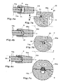
Figur 3 , bei der zwei er- findungsgemäße Verbindungseinrichtungen vorhanden sind, - Figuren 6a - 6c
- Querschnittsansichten eines Aufnahmebauteils und eines Bolzenbauteils bei einer Montage aneinander, etwa entsprechend einem Ausschnitt C in
Figur 2 , jedoch schematisiert, - Figuren 7a - 7c
- Teilausschnitte D aus den
Figuren 6a - 6c , - Figuren 8a - 8c
- perspektivische Schrägansichten einer Montage der in
Figuren 6a - 6c im Schnitt dargestellten Kompo- nenten, und - Figur 9
- eine perspektive Schrägansicht eines weiteren Aus- führungsbeispiels der Erfindung, bei dem ein Bol- zenbauteil und ein Aufnahmebauteil verdrehsicher miteinander verbunden sind.
- FIG. 1
- 2 is a perspective oblique view of a trailer coupling whose coupling arm can be attached to a vehicle-mounted holder, wherein a coupling device according to the invention is used in the coupling arm,
- FIG. 2
- a cross-sectional view of the hitch according to
FIG. 1 approximately along a section line AA, - FIG. 3
- 3 shows a side view of a further trailer coupling with a coupling arm, which is pivotable with respect to the vehicle-fixed holder and has a locking arrangement equipped with a connecting device according to the invention;
- FIG. 4
- a sectional view of the hitch according to
FIG. 3 approximately along a section line BB, - FIG. 5
- a sectional view of an actuator of the hitch according to
FIG. 3 in which two connecting devices according to the invention are present, - Figures 6a - 6c
- Cross-sectional views of a receiving component and a bolt component during assembly to each other, approximately corresponding to a cutout C in
FIG. 2 but schematized, - FIGS. 7a-7c
- Partial sections D from the
Figures 6a - 6c . - FIGS. 8a-8c
- perspective oblique views of an assembly of in
Figures 6a - 6c components shown in section, and - FIG. 9
- a perspective oblique view of another embodiment of the invention, in which a bolt member and a receiving member are connected to each other against rotation.
Bei der nachfolgenden Beschreibung sind gleiche oder gleichartige Bauteile mit denselben Bezugszeichen versehen. Zur Verdeutlichung von Unterschieden sind teilweise die Buchstaben a-d verwendet.In the following description, identical or similar components are provided with the same reference numerals. To clarify differences, the letters a-d are sometimes used.
Bei den Anhängekupplungen 10a (
Während die Anhängekupplung 10a eine Steck-Anhängekupplung ist, bei der der Kupplungsarm 12a an den Fahrzeug-Halter 11a ansteckbar ist, handelt es sich bei der Anhängekupplung 10b um eine Anhängekupplung, bei der der Kupplungsarm stets am Heck des Kraftfahrzeuges 17 verbleibt, dort aber beweglich gelagert ist, vorliegend drehbar (eine Verschiebelagerung oder auch eine Verschiebe-Drehlagerung sind ebenfalls möglich).While the
Bei der Anhängekupplung 10a ist ein Kupplungsarm-Steckabschnitt 18a des Kupplungsarmes 12a in eine Steckaufnahme 19a des Fahrzeug-Halters 11a einsteckbar entlang einer Steckachse 24a.In the
Bei der Anhängekupplung 10b ist ein Kupplungsarm-Lagerteil 18b an einem fahrzeugfest angeordneten Lagerkopf 19b des Fahrzeug-Halters 11b schwenkbar um eine Schiebeachse 24b gelagert.In the case of the
Die beiden Fahrzeug-Halter 11a, 11b haben fahrzeugfeste Anschläge, gegen die der Kupplungsarm 12a, 12b spannbar ist. Beispielsweise ist bei den Fahrzeug-Haltern 11a, 11b jeweils eine Flanschplatte 20a, 20b vorgesehen, gegen die eine Flanschplatte 21a bzw. eine Flanschfläche 21b spannbar ist. Die Flanschplatte 21a steht nach radial außen vor den Kupplungsarm 12a vor. Die Flanschfläche 21b ist eine Stirnseitenfläche des Kupplungsarm-Lagers 18b.The two
Der Kupplungsarm 12a, 12b ist am Fahrzeug-Halter 11a, 11b jeweils verdrehfest anordenbar. Dazu sind beispielsweise an den Flanschplatten 20a, 20b einerseits und der Flanschplatte 21a bzw. der Flanschfläche 21b andererseits Formschlusskörper 22 sowie Formschlussaufnahmen 23 vorgesehen. Die Formschlusskörper 22 sind beispielsweise Kugeln, während die Formschlussaufnahmen 23 dazu passende Kugelkalotten sind. Es versteht sich, dass auch auf andere Weise ein Formschluss herstellbar ist, beispielsweise in der Art von Keilflächen und Keilaufnahmen, die bei einer Anhängekupplung gemäß
Zur Verriegelung der Kupplungsarme 12a, 12b am Fahrzeug-Halter 11a, 11b dienen Verriegelungsanordnungen 30a, 30b mit Verriegelungsbolzen 31a, 31b. Diese sind in einem Aufnahmeraum 26 eines Steckendes 25a des Kupplungsarms 12a sowie eines Lagerrohrs 25b des Fahrzeug-Halters 11b vorgesehen. Das Lagerrohr 25b bildet eine Art Hohlwelle und somit einen Bestandteil eines Schwenklagers, mit dem das Kupplungsarm-Lagerteil 18b bezüglich des Fahrzeug-Halters 11b schwenkbar gelagert ist.Locking
Die Verriegelungsbolzen 31a, 31b umfassen jeweils ein Stangenteil 32a, 32b, das in erfinderungsgemäßer Weise mit einem Verdrängerkopf 33a, 33b zugfest verbunden ist.The locking
An den Umfangsseiten der Verdrängerköpfe 33a, 33b sind jeweils Verdrängerflächen 34 vorgesehen, mit denen Verriegelungselemente, vorliegend beispielsweise Kugeln (wobei auch Wälzelemente oder dergleichen denkbar sind) nach radial außen durch Kanäle 36 hindurch in Formschlussaufnahmen 37 verdrängbar sind, die am Fahrzeug-Halter 11a bzw. am Kupplungsarm-Lagerteil 18b vorgesehen sind. Die Kanäle 36 verlaufen von den jeweiligen Aufnahmeräumen 26 nach radial außen am Steckende 25a bzw. Lagerrohr 25b. Die Formschlussaufnahmen 37 sind durch Ringnuten an Ringen 38a, 38b gebildet, die ortsfest an der Steckaufnahme 19a bzw. in einem Innenraum des Kupplungsarm-Lagerteils 18b angeordnet sind.On the peripheral sides of the displacement heads 33a, 33b respectively displacement surfaces 34 are provided with which locking elements, in this case for example balls (whereby rolling elements or the like are conceivable) radially outward through
Gegenüber der Verriegelungsanordnung 30a weist die Verriegelungsanordnung 30b noch die Besonderheit auf, dass sie Lösemittel zum Lösen der Verriegelung umfasst, ähnlich wie die Anhängekupplung
Bei der Anhängekupplung 10a ist weiterhin ein schwenkbarer Steckdosenhalter 28 vorhanden, der zwischen einer Gebrauchsstellung einer Nichtgebrauchsstellung verschwenkbar ist.In the
Die beiden Verriegelungsbolzen 31a, 31b werden durch eine Federanordnung 45 in ihre Verriegelungsstellung beaufschlagt. Die Federanordnungen 45 umfassen jeweils eine Feder 46, die sich einerseits an einer Boden-Stützfläche 47 und andererseits an einer Kopf-Stützfläche 48 abstützt. Die Boden-Stützflächen 47 sind durch Bodenflächen der Aufnahmeräume 26 gebildet, während die Kopf-Stützflächen 48 an den Unterseiten der Verdrängerköpfe 33a, 33b vorgesehen sind. Die Stangenteile 32a, 32b durchdringen die Federn 46.The two locking
Zum Lösen der Verriegelungsanordnungen 30a, 30b sind Betätigungseinrichtungen 55a, 55b vorgesehen. Diese wirken jeweils auf einen Betätigungsabschnitt 50 der Stangenteile 32 und ermöglichen ein Lösen der Verriegelungsanordnungen 30a, 30b entgegen der Kraft der Federn 46.
Die Betätigungseinrichtungen 55a, 55b umfassen jeweils ein Handrad 56a, 56b, das von einem Bediener ergriffen und gedreht werden kann, um auf die Betätigungsabschnitte 50 im Sinne eines Lösens zu wirken.The
Das Handrad 56a ist drehfest mit einem Zahnrad 54a gekoppelt, das in eine Zahnung 53a, mithin also einem Zahnstangenabschnitt, am Betätigungsabschnitt 50 kämmt.The
Die Betätigungseinrichtung 55b erlaubt eine Betätigung aus der Ferne. Das Handrad 56b ist beispielsweise an einem Gehäuse 60 vorgesehen, dass im Innenraum des Kraftfahrzeugs 17, z.B. im Gepäckraum, anordenbar ist. Zwischen dem Gehäuse 60 und dem Fahrzeug-Halter 11b verläuft ein Bowdenzug 52, der mit dem Verriegelungsbolzen 31b zugfest gekoppelt ist, beispielsweise mit einem Zugabschnitt 51 desselben fest verbunden ist.The
Das Handrad 56b ist über einen Bolzen 57 mit einem Zahnrad 54b drehfest verbunden, das seinerseits mit einem Zahnstangenteil 58 eines Bowdenzug-Anschlussstücks 59 kämmt. Das Bowdenzug-Anschlussstück 59 ist mit dem Bowdenzug 52 zugfest verbunden.The
Die Verriegelungsanordnungen 30a, 30b müssen verhältnismäßig große Verriegelungskräfte ausüben, um die Kupplungsarme 12a, 12b möglichst spielarm an den Fahrzeug-Haltern 11a, 11b zu halten und zu verriegeln. Beim Fahrbetrieb des Kraftfahrzeugs 17 treten nämlich verhältnismäßig große Kräfte auf, die auf den Kupplungsarm 12a, 12b wirken. Obwohl an die Verbindung der einzelnen Komponenten der Verriegelungsanordnungen 30a, 30b sowie der Betätigungseinrichtungen 55a, 55b große Anforderungen hinsichtlich der Festigkeit und auch sonstigen Belastbarkeit gestellt sind, ist deren Montage durch die nachfolgend erläuterte erfindungsgemäße Verbindungstechnik erleichtert:
Die Stangenteile 32a, 32b sowie der eine Zahnung oder ein Zahnrad 54b aufweisende Bolzen 57 und das Bowdenzug-Anschlussstück 59 bilden Bolzenbauteile 70a-70d, die jeweils einen Steckkopf 71 aufweisen, der in korrespondierende Steckaufnahmen 81 von Aufnahmebauteilen 80b-80d einsteckbar ist. Die Verdrängerköpfe 33a, 33b bilden die Aufnahmebauteile 80a, 80b. Das Aufnahmebauteil 80c wird durch das Handrad 56b gebildet. Das Aufnahmebauteil 80d durch einen Bowdenzug-Anschluss 61, der mit dem Bowdenzug-Anschlussstück 59 erfindungsgemäß zugfest verbunden ist und zudem auch mit dem Zug-/Druckseil des Bowdenzugs 52 zug- und druckfest verbunden ist. Man kann sich beispielsweise eine Konfiguration vorstellen, bei dem das Zug-/Druckseil des Bowdenzugs 52 mit dem Bowdenzug-Anschluss 61 verschweißt oder verklebt ist oder das an dem Zugseil frontseitig eine Steckaufnahme 81 vorgesehen ist.The locking
The
Die Verbindungen zwischen den Bolzenbauteilen 70a-70d und den Aufnahmebauteilen 80a-80d sind erfindungsgemäß hergestellt und werden nachfolgend anhand der
An dem Steckkopf 71 ist eine Bolzenbauteil-Aufnahme 72 in der Art einer Ringnut 73 vorgesehen. Korrespondierend zur Ringnut 73 und in Steckstellung des Bolzenbauteils 70a am Aufnahmebauteil 80a mit dieser fluchtend ist am Aufnahmebauteil 80a eine Aufnahmebauteil-Aufnahme 82 in Gestalt einer Ringnut 83 vorgesehen.On the
Eine bevorzugte Montage der in den
An einem freien Ende des Bolzenbauteils 70a ist ein Konus 74 vorhanden, der ein Aufspreizen des Sprengringes 91 erleichtert. Der Sprengring 91 wird also von der freien Seite des Stangenteils 32a her auf den Konus 74 aufgesteckt. Der Konus 74 stellt eine Aufweitschräge 77 dar, die zum Aufweiten des Sprengringes 91 geeignet ist. Beim Verschieben des Sprengringes 91 entlang der Steckachse 100 weitet sich also der Sprengring 91 auf, bis er in den Bereich der Ringnut 73 gelangt, so dass er aus seiner aufgeweiteten Stellung wieder zurück in eine entspannte Stellung gelangen kann. Der Sprengring 91 hat dabei einen Abstand von einem Boden der Ringnut 73, die eine geeignete Tiefe 75 dafür aufweist, siehe
At a free end of the
Sodann wird das Bolzenbauteil 70a entlang der Steckachse 100 in Richtung der Steckaufnahme 81 verschoben, das heißt in die Steckaufnahme 81 eingesteckt, siehe
In
Beim Ausführungsbeispiel ist die Anordnung bzw. Tiefe der Ringnuten 73, 83 so getroffen, dass die Tiefe 75 ausreicht, um den Sprengring 91 in seiner Kompressionsstellung bzw. Spannstellung S vollständig aufzunehmen. Somit steht er also nicht vor einen Außenumfang des Bolzenbauteils 70a störend vor, so dass dieses ohne ein Hindernis in die Steckaufnahme 81 eingeschoben werden kann, siehe
Ein Durchmesser 85 der Ringnut 83 bzw. Aufnahmebauteil-Aufnahme 82 ist nunmehr so getroffen, dass der Sprengring 91 sich nicht vollständig entspannen kann, sondern unter seiner eigenen Federspannung am Nutboden bzw. Boden der Aufnahme 82 anliegt, siehe
Der stirnseitige Konus 74 des Bolzenbauteils 70 sowie der Einführkonus bzw. Kompressionskonus 84 erleichtern zudem ein Einstecken des Bolzenbauteils 70a in die Steckaufnahme 81. Die Verbindungseinrichtung 65 gemäß
Allerdings sind auch verdrehfeste oder zumindest in einer Richtung verdrehgesicherte Verbindungen mit einer erfindungsgemäßen Verbindungseinrichtung möglich. Eine verdrehgesicherte Verbindung ist beispielsweise bei der Betätigungseinrichtung 55b zwischen einerseits den Bolzenbauteilen 70c, 70d und andererseits den Aufnahmebauteilen 80c und 80d zweckmäßig. Am Beispiel der Verbindung zwischen den Bauteilen 70c, 80c ist dies in
Drehanschläge 99 legen das Bolzenbauteil 70c am Aufnahmebauteil 80c drehfest fest. Die Drehanschläge 99 umfassen am Außenumfang des Bolzenbauteils 70c angeordnete Drehmitnahmevorsprünge 94, die in korrespondierende Drehmitnahmeaufnahmen 95, beispielsweise Nuten, am Innenumfang der Steckaufnahme 81 eingreifen.Rotation stops 99 fix the
Weiterhin stützen sich Stirnseitenflächen 92, die insoweit Drehanschläge 99 bilden, an Anschlagflächen 76 ab, die im Bereich der Bolzenbauteil-Aufnahme 72 vorgesehen sind. Die Anschlagflächen 76 haben einen Umfangsabstand, der dem Umfangsabstand der Stirnseitenflächen 92 entspricht. Somit kann sich der Sprengring 91 in der Bolzenbauteil-Aufnahme 72 nicht drehen. Der Sprengring 91 kann sich aber auch in der in der Steckaufnahme 81 angeordneten Aufnahmebauteil-Aufnahme 82 nicht drehen, weil auch diese entsprechende Anschlagflächen 76 aufweist. Somit wirkt also das Verbindungselement 90 bzw. der Sprengring 91 in Verbindung mit den Anschlagflächen 76 als Verdrehsicherung.Furthermore, end faces 92, which in this respect form rotational stops 99, are supported on abutment surfaces 76, which are provided in the region of the
Allerdings ist eine solche Verdrehsicherung mit einem gewissen Spiel behaftet. Damit sich nämlich der Sprengring 91 beim Aufschieben auf das Bolzenbauteil 70c aufweiten lässt oder beim Einstecken in das Aufnahmebauteil 80c komprimieren lässt, ist ein Abstand zwischen den Anschlagflächen 76 etwas kleiner als ein Umfangsabstand zwischen den Stirnseitenflächen 92. Wenn sich der Sprengring 91 anschließend in seiner Befestigungsstellung B befindet, haben also seine Stirnseitenflächen 92 bezüglich der Anschlagflächen 76 ein gewisses Drehspiel.However, such a rotation is associated with a certain game. Thus, the
Es versteht sich, dass die erfindungsgemäße Verbindungseinrichtung auch bei Lastenträgern zum Auflegen einer Last anwendbar ist, beispielsweise bei solchen, die auf einer Anhängekupplung montierbar sind oder die auch fahrzeugfest sind. Beispielsweise kann man einen solchen Lastenträger in der Art einer Schublade aus dem Heck eines Kraftfahrzeuges ausziehen. Auch dort sind Steckaufnahmen denkbar, in die ein entsprechendes Bolzenbauteil eingreift, beispielsweise zur Realisierung einer Drehwelle oder eines Drehlagers.It is understood that the connecting device according to the invention is also applicable to load carriers for applying a load, for example, those that are mounted on a trailer hitch or that are also fixed to the vehicle. For example, you can take off such a load carrier in the manner of a drawer from the rear of a motor vehicle. Also there plug-in receptacles are conceivable, in which engages a corresponding pin member, for example, to realize a rotary shaft or a pivot bearing.
Claims (15)
Applications Claiming Priority (1)
| Application Number | Priority Date | Filing Date | Title |
|---|---|---|---|
| DE200920014826 DE202009014826U1 (en) | 2009-11-03 | 2009-11-03 | Connecting device for a trailer hitch or a load carrier |
Publications (2)
| Publication Number | Publication Date |
|---|---|
| EP2316673A1 true EP2316673A1 (en) | 2011-05-04 |
| EP2316673B1 EP2316673B1 (en) | 2012-12-26 |
Family
ID=43528342
Family Applications (1)
| Application Number | Title | Priority Date | Filing Date |
|---|---|---|---|
| EP20100013977 Active EP2316673B1 (en) | 2009-11-03 | 2010-10-26 | Connection device for a trailer coupling or a load bearer |
Country Status (2)
| Country | Link |
|---|---|
| EP (1) | EP2316673B1 (en) |
| DE (2) | DE202009014826U1 (en) |
Families Citing this family (2)
| Publication number | Priority date | Publication date | Assignee | Title |
|---|---|---|---|---|
| DE102012216798A1 (en) * | 2012-09-19 | 2014-03-20 | Zf Friedrichshafen Ag | Ball swivel module |
| DE102014221742A1 (en) * | 2014-10-27 | 2016-04-28 | Zf Friedrichshafen Ag | Swivel module of a trailer hitch |
Citations (8)
| Publication number | Priority date | Publication date | Assignee | Title |
|---|---|---|---|---|
| US2549178A (en) * | 1947-01-01 | 1951-04-17 | Brockhouse J & Co Ltd | Ball-and-socket coupling |
| DE1116067B (en) * | 1960-03-14 | 1961-10-26 | Josef Schmitz | Clamping bush for drawbar eyes |
| DE8423990U1 (en) * | 1984-08-13 | 1987-03-05 | Smat-Fahrzeugtechnik Gmbh, 6325 Grebenau, De | |
| DE19540336A1 (en) | 1994-11-02 | 1996-05-30 | Westfalia Werke Knoebel | Securing fixture for trailer mount to vehicle |
| DE19701273A1 (en) | 1996-01-24 | 1997-07-31 | Westfalia Werke Knoebel | Coupling for trailer on road vehicle |
| DE19712273A1 (en) | 1996-03-30 | 1997-11-06 | Samsung Electronics Co Ltd | Method for sending absence messages in an ISDN switching system |
| EP1475253A1 (en) | 2003-05-07 | 2004-11-10 | Westfalia Automotive GmbH & Co. KG | Trailer coupling for motor vehicles |
| EP1985473A1 (en) * | 2007-04-25 | 2008-10-29 | WESTFALIA - Automotive GmbH | Draw bar with an actuation device |
Family Cites Families (4)
| Publication number | Priority date | Publication date | Assignee | Title |
|---|---|---|---|---|
| JP3343589B2 (en) * | 1993-07-30 | 2002-11-11 | スズキ株式会社 | Lock device |
| DE29501158U1 (en) * | 1995-01-25 | 1995-03-30 | Electrolux Corporate Patents & | Locking device for a drive shaft |
| DE10053641A1 (en) * | 2000-10-28 | 2002-05-02 | Deere & Co | Locking device to secure insertion part in receiving part has depth of annular groove in external surface less than thickness of spring ring |
| DE102006008837A1 (en) * | 2006-02-27 | 2007-09-06 | Westfalia-Automotive Gmbh | Towbar for motor vehicles |
-
2009
- 2009-11-03 DE DE200920014826 patent/DE202009014826U1/en not_active Expired - Lifetime
-
2010
- 2010-10-26 EP EP20100013977 patent/EP2316673B1/en active Active
- 2010-10-26 DE DE102010049384A patent/DE102010049384A1/en not_active Withdrawn
Patent Citations (8)
| Publication number | Priority date | Publication date | Assignee | Title |
|---|---|---|---|---|
| US2549178A (en) * | 1947-01-01 | 1951-04-17 | Brockhouse J & Co Ltd | Ball-and-socket coupling |
| DE1116067B (en) * | 1960-03-14 | 1961-10-26 | Josef Schmitz | Clamping bush for drawbar eyes |
| DE8423990U1 (en) * | 1984-08-13 | 1987-03-05 | Smat-Fahrzeugtechnik Gmbh, 6325 Grebenau, De | |
| DE19540336A1 (en) | 1994-11-02 | 1996-05-30 | Westfalia Werke Knoebel | Securing fixture for trailer mount to vehicle |
| DE19701273A1 (en) | 1996-01-24 | 1997-07-31 | Westfalia Werke Knoebel | Coupling for trailer on road vehicle |
| DE19712273A1 (en) | 1996-03-30 | 1997-11-06 | Samsung Electronics Co Ltd | Method for sending absence messages in an ISDN switching system |
| EP1475253A1 (en) | 2003-05-07 | 2004-11-10 | Westfalia Automotive GmbH & Co. KG | Trailer coupling for motor vehicles |
| EP1985473A1 (en) * | 2007-04-25 | 2008-10-29 | WESTFALIA - Automotive GmbH | Draw bar with an actuation device |
Also Published As
| Publication number | Publication date |
|---|---|
| EP2316673B1 (en) | 2012-12-26 |
| DE102010049384A1 (en) | 2011-05-05 |
| DE202009014826U1 (en) | 2011-03-17 |
Similar Documents
| Publication | Publication Date | Title |
|---|---|---|
| EP1902870B1 (en) | Towing device for a towing vehicle | |
| EP2792514B1 (en) | Trailer coupling | |
| DE102009038317B4 (en) | Adjustable steering column for a motor vehicle | |
| EP2149460B1 (en) | Trailer tow-bar | |
| EP2792513B1 (en) | Trailer coupling | |
| EP1946947B1 (en) | Coupling device with an interlocking device with activation ring | |
| EP2316673B1 (en) | Connection device for a trailer coupling or a load bearer | |
| EP3098094B1 (en) | Draw coupling with a pivot bearing | |
| EP2799261B1 (en) | Trailer coupling | |
| EP3098097B1 (en) | Trailer coupling | |
| EP3219520B1 (en) | Trailer coupling system for motor vehicles | |
| EP3098096A2 (en) | Draw bar with a fixing device | |
| DE102014005881A1 (en) | Towing | |
| EP2796304B1 (en) | Tow bar | |
| EP2796303B1 (en) | Trailer coupling | |
| EP2796305B1 (en) | Trailer coupling | |
| EP3012128B1 (en) | Coupling device comprising a fixing unit | |
| EP3098095B1 (en) | Draw bar with a fixing device | |
| DE102007003773A1 (en) | Towing device for towing vehicle, has positive locking element movably supported at positive locking element bearing, and engaging in locking position in positive locking receiver at outer circumference of coupling arm | |
| DE102010050015A1 (en) | Locking device for steering column of motor vehicle, has catch element with catch element-sided sliding function surface, where catch element is integrally formed with clamping surface element | |
| DE102020128980A1 (en) | Trailer hitch with a locking device | |
| DE102013007123A1 (en) | Towing | |
| EP2256000A1 (en) | Slidable load carrier with a clamping device |
Legal Events
| Date | Code | Title | Description |
|---|---|---|---|
| PUAI | Public reference made under article 153(3) epc to a published international application that has entered the european phase |
Free format text: ORIGINAL CODE: 0009012 |
|
| AK | Designated contracting states |
Kind code of ref document: A1 Designated state(s): AL AT BE BG CH CY CZ DE DK EE ES FI FR GB GR HR HU IE IS IT LI LT LU LV MC MK MT NL NO PL PT RO RS SE SI SK SM TR |
|
| AX | Request for extension of the european patent |
Extension state: BA ME |
|
| 17P | Request for examination filed |
Effective date: 20110506 |
|
| GRAP | Despatch of communication of intention to grant a patent |
Free format text: ORIGINAL CODE: EPIDOSNIGR1 |
|
| GRAS | Grant fee paid |
Free format text: ORIGINAL CODE: EPIDOSNIGR3 |
|
| GRAP | Despatch of communication of intention to grant a patent |
Free format text: ORIGINAL CODE: EPIDOSNIGR1 |
|
| GRAA | (expected) grant |
Free format text: ORIGINAL CODE: 0009210 |
|
| AK | Designated contracting states |
Kind code of ref document: B1 Designated state(s): AL AT BE BG CH CY CZ DE DK EE ES FI FR GB GR HR HU IE IS IT LI LT LU LV MC MK MT NL NO PL PT RO RS SE SI SK SM TR |
|
| REG | Reference to a national code |
Ref country code: GB Ref legal event code: FG4D Free format text: NOT ENGLISH |
|
| REG | Reference to a national code |
Ref country code: CH Ref legal event code: EP |
|
| REG | Reference to a national code |
Ref country code: AT Ref legal event code: REF Ref document number: 590241 Country of ref document: AT Kind code of ref document: T Effective date: 20130115 |
|
| REG | Reference to a national code |
Ref country code: DE Ref legal event code: R096 Ref document number: 502010001937 Country of ref document: DE Effective date: 20130314 |
|
| PG25 | Lapsed in a contracting state [announced via postgrant information from national office to epo] |
Ref country code: FI Free format text: LAPSE BECAUSE OF FAILURE TO SUBMIT A TRANSLATION OF THE DESCRIPTION OR TO PAY THE FEE WITHIN THE PRESCRIBED TIME-LIMIT Effective date: 20121226 Ref country code: NO Free format text: LAPSE BECAUSE OF FAILURE TO SUBMIT A TRANSLATION OF THE DESCRIPTION OR TO PAY THE FEE WITHIN THE PRESCRIBED TIME-LIMIT Effective date: 20130326 Ref country code: HR Free format text: LAPSE BECAUSE OF FAILURE TO SUBMIT A TRANSLATION OF THE DESCRIPTION OR TO PAY THE FEE WITHIN THE PRESCRIBED TIME-LIMIT Effective date: 20121226 Ref country code: LT Free format text: LAPSE BECAUSE OF FAILURE TO SUBMIT A TRANSLATION OF THE DESCRIPTION OR TO PAY THE FEE WITHIN THE PRESCRIBED TIME-LIMIT Effective date: 20121226 Ref country code: SE Free format text: LAPSE BECAUSE OF FAILURE TO SUBMIT A TRANSLATION OF THE DESCRIPTION OR TO PAY THE FEE WITHIN THE PRESCRIBED TIME-LIMIT Effective date: 20121226 |
|
| REG | Reference to a national code |
Ref country code: LT Ref legal event code: MG4D |
|
| REG | Reference to a national code |
Ref country code: NL Ref legal event code: VDEP Effective date: 20121226 |
|
| PG25 | Lapsed in a contracting state [announced via postgrant information from national office to epo] |
Ref country code: SI Free format text: LAPSE BECAUSE OF FAILURE TO SUBMIT A TRANSLATION OF THE DESCRIPTION OR TO PAY THE FEE WITHIN THE PRESCRIBED TIME-LIMIT Effective date: 20121226 Ref country code: GR Free format text: LAPSE BECAUSE OF FAILURE TO SUBMIT A TRANSLATION OF THE DESCRIPTION OR TO PAY THE FEE WITHIN THE PRESCRIBED TIME-LIMIT Effective date: 20130327 Ref country code: LV Free format text: LAPSE BECAUSE OF FAILURE TO SUBMIT A TRANSLATION OF THE DESCRIPTION OR TO PAY THE FEE WITHIN THE PRESCRIBED TIME-LIMIT Effective date: 20121226 |
|
| PG25 | Lapsed in a contracting state [announced via postgrant information from national office to epo] |
Ref country code: IS Free format text: LAPSE BECAUSE OF FAILURE TO SUBMIT A TRANSLATION OF THE DESCRIPTION OR TO PAY THE FEE WITHIN THE PRESCRIBED TIME-LIMIT Effective date: 20130426 Ref country code: SK Free format text: LAPSE BECAUSE OF FAILURE TO SUBMIT A TRANSLATION OF THE DESCRIPTION OR TO PAY THE FEE WITHIN THE PRESCRIBED TIME-LIMIT Effective date: 20121226 Ref country code: BG Free format text: LAPSE BECAUSE OF FAILURE TO SUBMIT A TRANSLATION OF THE DESCRIPTION OR TO PAY THE FEE WITHIN THE PRESCRIBED TIME-LIMIT Effective date: 20130326 Ref country code: ES Free format text: LAPSE BECAUSE OF FAILURE TO SUBMIT A TRANSLATION OF THE DESCRIPTION OR TO PAY THE FEE WITHIN THE PRESCRIBED TIME-LIMIT Effective date: 20130406 Ref country code: CZ Free format text: LAPSE BECAUSE OF FAILURE TO SUBMIT A TRANSLATION OF THE DESCRIPTION OR TO PAY THE FEE WITHIN THE PRESCRIBED TIME-LIMIT Effective date: 20121226 Ref country code: EE Free format text: LAPSE BECAUSE OF FAILURE TO SUBMIT A TRANSLATION OF THE DESCRIPTION OR TO PAY THE FEE WITHIN THE PRESCRIBED TIME-LIMIT Effective date: 20121226 Ref country code: RS Free format text: LAPSE BECAUSE OF FAILURE TO SUBMIT A TRANSLATION OF THE DESCRIPTION OR TO PAY THE FEE WITHIN THE PRESCRIBED TIME-LIMIT Effective date: 20121226 |
|
| PG25 | Lapsed in a contracting state [announced via postgrant information from national office to epo] |
Ref country code: RO Free format text: LAPSE BECAUSE OF FAILURE TO SUBMIT A TRANSLATION OF THE DESCRIPTION OR TO PAY THE FEE WITHIN THE PRESCRIBED TIME-LIMIT Effective date: 20121226 Ref country code: PL Free format text: LAPSE BECAUSE OF FAILURE TO SUBMIT A TRANSLATION OF THE DESCRIPTION OR TO PAY THE FEE WITHIN THE PRESCRIBED TIME-LIMIT Effective date: 20121226 Ref country code: PT Free format text: LAPSE BECAUSE OF FAILURE TO SUBMIT A TRANSLATION OF THE DESCRIPTION OR TO PAY THE FEE WITHIN THE PRESCRIBED TIME-LIMIT Effective date: 20130426 Ref country code: NL Free format text: LAPSE BECAUSE OF FAILURE TO SUBMIT A TRANSLATION OF THE DESCRIPTION OR TO PAY THE FEE WITHIN THE PRESCRIBED TIME-LIMIT Effective date: 20121226 |
|
| PG25 | Lapsed in a contracting state [announced via postgrant information from national office to epo] |
Ref country code: DK Free format text: LAPSE BECAUSE OF FAILURE TO SUBMIT A TRANSLATION OF THE DESCRIPTION OR TO PAY THE FEE WITHIN THE PRESCRIBED TIME-LIMIT Effective date: 20121226 |
|
| PLBE | No opposition filed within time limit |
Free format text: ORIGINAL CODE: 0009261 |
|
| STAA | Information on the status of an ep patent application or granted ep patent |
Free format text: STATUS: NO OPPOSITION FILED WITHIN TIME LIMIT |
|
| PG25 | Lapsed in a contracting state [announced via postgrant information from national office to epo] |
Ref country code: CY Free format text: LAPSE BECAUSE OF FAILURE TO SUBMIT A TRANSLATION OF THE DESCRIPTION OR TO PAY THE FEE WITHIN THE PRESCRIBED TIME-LIMIT Effective date: 20121226 |
|
| 26N | No opposition filed |
Effective date: 20130927 |
|
| PG25 | Lapsed in a contracting state [announced via postgrant information from national office to epo] |
Ref country code: IT Free format text: LAPSE BECAUSE OF FAILURE TO SUBMIT A TRANSLATION OF THE DESCRIPTION OR TO PAY THE FEE WITHIN THE PRESCRIBED TIME-LIMIT Effective date: 20121226 |
|
| REG | Reference to a national code |
Ref country code: DE Ref legal event code: R097 Ref document number: 502010001937 Country of ref document: DE Effective date: 20130927 |
|
| BERE | Be: lapsed |
Owner name: WESTFALIA - AUTOMOTIVE G.M.B.H. Effective date: 20131031 |
|
| PG25 | Lapsed in a contracting state [announced via postgrant information from national office to epo] |
Ref country code: MC Free format text: LAPSE BECAUSE OF FAILURE TO SUBMIT A TRANSLATION OF THE DESCRIPTION OR TO PAY THE FEE WITHIN THE PRESCRIBED TIME-LIMIT Effective date: 20121226 |
|
| REG | Reference to a national code |
Ref country code: IE Ref legal event code: MM4A |
|
| REG | Reference to a national code |
Ref country code: DE Ref legal event code: R082 Ref document number: 502010001937 Country of ref document: DE Representative=s name: BREGENZER, MICHAEL, DIPL.-ING., DE Ref country code: DE Ref legal event code: R082 Ref document number: 502010001937 Country of ref document: DE Representative=s name: PATENTANWAELTE BREGENZER UND REULE PARTNERSCHA, DE |
|
| PG25 | Lapsed in a contracting state [announced via postgrant information from national office to epo] |
Ref country code: BE Free format text: LAPSE BECAUSE OF NON-PAYMENT OF DUE FEES Effective date: 20131031 |
|
| PG25 | Lapsed in a contracting state [announced via postgrant information from national office to epo] |
Ref country code: IE Free format text: LAPSE BECAUSE OF NON-PAYMENT OF DUE FEES Effective date: 20131026 |
|
| REG | Reference to a national code |
Ref country code: DE Ref legal event code: R082 Ref document number: 502010001937 Country of ref document: DE Representative=s name: PATENTANWAELTE BREGENZER UND REULE PARTNERSCHA, DE |
|
| PG25 | Lapsed in a contracting state [announced via postgrant information from national office to epo] |
Ref country code: SM Free format text: LAPSE BECAUSE OF FAILURE TO SUBMIT A TRANSLATION OF THE DESCRIPTION OR TO PAY THE FEE WITHIN THE PRESCRIBED TIME-LIMIT Effective date: 20121226 |
|
| REG | Reference to a national code |
Ref country code: CH Ref legal event code: PL |
|
| GBPC | Gb: european patent ceased through non-payment of renewal fee |
Effective date: 20141026 |
|
| PG25 | Lapsed in a contracting state [announced via postgrant information from national office to epo] |
Ref country code: TR Free format text: LAPSE BECAUSE OF FAILURE TO SUBMIT A TRANSLATION OF THE DESCRIPTION OR TO PAY THE FEE WITHIN THE PRESCRIBED TIME-LIMIT Effective date: 20121226 |
|
| PG25 | Lapsed in a contracting state [announced via postgrant information from national office to epo] |
Ref country code: GB Free format text: LAPSE BECAUSE OF NON-PAYMENT OF DUE FEES Effective date: 20141026 Ref country code: CH Free format text: LAPSE BECAUSE OF NON-PAYMENT OF DUE FEES Effective date: 20141031 Ref country code: LU Free format text: LAPSE BECAUSE OF NON-PAYMENT OF DUE FEES Effective date: 20131026 Ref country code: LI Free format text: LAPSE BECAUSE OF NON-PAYMENT OF DUE FEES Effective date: 20141031 Ref country code: HU Free format text: LAPSE BECAUSE OF FAILURE TO SUBMIT A TRANSLATION OF THE DESCRIPTION OR TO PAY THE FEE WITHIN THE PRESCRIBED TIME-LIMIT; INVALID AB INITIO Effective date: 20101026 Ref country code: MK Free format text: LAPSE BECAUSE OF FAILURE TO SUBMIT A TRANSLATION OF THE DESCRIPTION OR TO PAY THE FEE WITHIN THE PRESCRIBED TIME-LIMIT Effective date: 20121226 |
|
| PG25 | Lapsed in a contracting state [announced via postgrant information from national office to epo] |
Ref country code: MT Free format text: LAPSE BECAUSE OF FAILURE TO SUBMIT A TRANSLATION OF THE DESCRIPTION OR TO PAY THE FEE WITHIN THE PRESCRIBED TIME-LIMIT Effective date: 20121226 |
|
| REG | Reference to a national code |
Ref country code: FR Ref legal event code: PLFP Year of fee payment: 6 |
|
| REG | Reference to a national code |
Ref country code: FR Ref legal event code: PLFP Year of fee payment: 7 |
|
| REG | Reference to a national code |
Ref country code: AT Ref legal event code: MM01 Ref document number: 590241 Country of ref document: AT Kind code of ref document: T Effective date: 20151026 |
|
| PG25 | Lapsed in a contracting state [announced via postgrant information from national office to epo] |
Ref country code: AT Free format text: LAPSE BECAUSE OF NON-PAYMENT OF DUE FEES Effective date: 20151026 |
|
| REG | Reference to a national code |
Ref country code: FR Ref legal event code: PLFP Year of fee payment: 8 |
|
| REG | Reference to a national code |
Ref country code: FR Ref legal event code: PLFP Year of fee payment: 9 |
|
| PG25 | Lapsed in a contracting state [announced via postgrant information from national office to epo] |
Ref country code: AL Free format text: LAPSE BECAUSE OF FAILURE TO SUBMIT A TRANSLATION OF THE DESCRIPTION OR TO PAY THE FEE WITHIN THE PRESCRIBED TIME-LIMIT Effective date: 20121226 |
|
| PGFP | Annual fee paid to national office [announced via postgrant information from national office to epo] |
Ref country code: FR Payment date: 20231025 Year of fee payment: 14 Ref country code: DE Payment date: 20231027 Year of fee payment: 14 |