EP2315005B1 - Fluorometry device and method for detection in biological samples - Google Patents
Fluorometry device and method for detection in biological samples Download PDFInfo
- Publication number
- EP2315005B1 EP2315005B1 EP10013121.8A EP10013121A EP2315005B1 EP 2315005 B1 EP2315005 B1 EP 2315005B1 EP 10013121 A EP10013121 A EP 10013121A EP 2315005 B1 EP2315005 B1 EP 2315005B1
- Authority
- EP
- European Patent Office
- Prior art keywords
- excitation
- emission
- light
- sample
- fluorometry
- Prior art date
- Legal status (The legal status is an assumption and is not a legal conclusion. Google has not performed a legal analysis and makes no representation as to the accuracy of the status listed.)
- Active
Links
Images


Classifications
-
- G—PHYSICS
- G01—MEASURING; TESTING
- G01N—INVESTIGATING OR ANALYSING MATERIALS BY DETERMINING THEIR CHEMICAL OR PHYSICAL PROPERTIES
- G01N21/00—Investigating or analysing materials by the use of optical means, i.e. using sub-millimetre waves, infrared, visible or ultraviolet light
- G01N21/62—Systems in which the material investigated is excited whereby it emits light or causes a change in wavelength of the incident light
- G01N21/63—Systems in which the material investigated is excited whereby it emits light or causes a change in wavelength of the incident light optically excited
- G01N21/64—Fluorescence; Phosphorescence
- G01N21/645—Specially adapted constructive features of fluorimeters
- G01N21/6452—Individual samples arranged in a regular 2D-array, e.g. multiwell plates
-
- G—PHYSICS
- G01—MEASURING; TESTING
- G01N—INVESTIGATING OR ANALYSING MATERIALS BY DETERMINING THEIR CHEMICAL OR PHYSICAL PROPERTIES
- G01N21/00—Investigating or analysing materials by the use of optical means, i.e. using sub-millimetre waves, infrared, visible or ultraviolet light
- G01N21/17—Systems in which incident light is modified in accordance with the properties of the material investigated
- G01N21/25—Colour; Spectral properties, i.e. comparison of effect of material on the light at two or more different wavelengths or wavelength bands
- G01N21/251—Colorimeters; Construction thereof
- G01N21/253—Colorimeters; Construction thereof for batch operation, i.e. multisample apparatus
-
- G—PHYSICS
- G01—MEASURING; TESTING
- G01N—INVESTIGATING OR ANALYSING MATERIALS BY DETERMINING THEIR CHEMICAL OR PHYSICAL PROPERTIES
- G01N21/00—Investigating or analysing materials by the use of optical means, i.e. using sub-millimetre waves, infrared, visible or ultraviolet light
- G01N21/62—Systems in which the material investigated is excited whereby it emits light or causes a change in wavelength of the incident light
- G01N21/63—Systems in which the material investigated is excited whereby it emits light or causes a change in wavelength of the incident light optically excited
- G01N21/64—Fluorescence; Phosphorescence
- G01N21/6428—Measuring fluorescence of fluorescent products of reactions or of fluorochrome labelled reactive substances, e.g. measuring quenching effects, using measuring "optrodes"
- G01N2021/6439—Measuring fluorescence of fluorescent products of reactions or of fluorochrome labelled reactive substances, e.g. measuring quenching effects, using measuring "optrodes" with indicators, stains, dyes, tags, labels, marks
-
- G—PHYSICS
- G01—MEASURING; TESTING
- G01N—INVESTIGATING OR ANALYSING MATERIALS BY DETERMINING THEIR CHEMICAL OR PHYSICAL PROPERTIES
- G01N21/00—Investigating or analysing materials by the use of optical means, i.e. using sub-millimetre waves, infrared, visible or ultraviolet light
- G01N21/62—Systems in which the material investigated is excited whereby it emits light or causes a change in wavelength of the incident light
- G01N21/63—Systems in which the material investigated is excited whereby it emits light or causes a change in wavelength of the incident light optically excited
- G01N21/64—Fluorescence; Phosphorescence
- G01N21/645—Specially adapted constructive features of fluorimeters
- G01N2021/6463—Optics
- G01N2021/6471—Special filters, filter wheel
-
- G—PHYSICS
- G01—MEASURING; TESTING
- G01N—INVESTIGATING OR ANALYSING MATERIALS BY DETERMINING THEIR CHEMICAL OR PHYSICAL PROPERTIES
- G01N21/00—Investigating or analysing materials by the use of optical means, i.e. using sub-millimetre waves, infrared, visible or ultraviolet light
- G01N21/62—Systems in which the material investigated is excited whereby it emits light or causes a change in wavelength of the incident light
- G01N21/63—Systems in which the material investigated is excited whereby it emits light or causes a change in wavelength of the incident light optically excited
- G01N21/64—Fluorescence; Phosphorescence
- G01N21/645—Specially adapted constructive features of fluorimeters
- G01N2021/6463—Optics
- G01N2021/6473—In-line geometry
- G01N2021/6476—Front end, i.e. backscatter, geometry
-
- G—PHYSICS
- G01—MEASURING; TESTING
- G01N—INVESTIGATING OR ANALYSING MATERIALS BY DETERMINING THEIR CHEMICAL OR PHYSICAL PROPERTIES
- G01N21/00—Investigating or analysing materials by the use of optical means, i.e. using sub-millimetre waves, infrared, visible or ultraviolet light
- G01N21/62—Systems in which the material investigated is excited whereby it emits light or causes a change in wavelength of the incident light
- G01N21/63—Systems in which the material investigated is excited whereby it emits light or causes a change in wavelength of the incident light optically excited
- G01N21/64—Fluorescence; Phosphorescence
- G01N21/645—Specially adapted constructive features of fluorimeters
- G01N2021/6463—Optics
- G01N2021/6478—Special lenses
-
- G—PHYSICS
- G01—MEASURING; TESTING
- G01N—INVESTIGATING OR ANALYSING MATERIALS BY DETERMINING THEIR CHEMICAL OR PHYSICAL PROPERTIES
- G01N2201/00—Features of devices classified in G01N21/00
- G01N2201/02—Mechanical
- G01N2201/024—Modular construction
- G01N2201/0245—Modular construction with insertable-removable part
Definitions
- the present teaching relates to methods and systems for fluorescent detection in biological samples.
- PCR Polymerase chain reaction
- DNA double-stranded deoxyribonucleic acid
- Measurements can be taken, in situ, to monitor the performance of the PCR process.
- One measurement technique is microscopy. Microscopy can be used to spacially resolve features of interest in the DNA content of the sample based on dyes that fluoresce in the presence of DNA.
- microscopy systems are limited to viewing only one depth of view of the sample at a time, and thus, are unsuitable for making quantitative measurements, such as a concentration measurement.
- Fluorometry utilizes microvolume fluorometers (spectofluorometers) to spectrally resolve fluorescent light from the volume of biological sample to provide quantitative measurements such as concentration.
- Fluorometers can illuminate the sample and utilize dyes that fluoresce in the presence of DNA. The light that fluoresces from a dye can be quantitatively measured using an optical device and a detector without collimating the light through the optical device and without focusing the light from the sample on the detector.
- High-throughput systems can provide DNA amplification of multiple samples in parallel, such as in a microwell tray or microcard.
- Assays can provide multiple DNA target sequences of interest, such as diagnostic assays, for example, HIV screening. These assays can provide multiple spectrally distinguishable species, such as different fluorescent dyes, in each of the multiple samples thermally cycled in parallel.
- light emitted from the samples or the light source typically contains spatial non-uniformities. These spatial non-uniformities can be caused by diffraction or irregularities in emission. The non-uniformities can make it difficult to resolve the various features or to accurately determine the concentration of a given material in a sample. It is desirable, therefore, to have a system capable of solving the problems encountered by spatial non-uniformities.
- EP 1 347 285 A1 discloses an apparatus for fluorescence measurements on a bio chip.
- the apparatus comprises an illumination unit having a light source which projects light onto filter sets through a lens.
- the fluorescent measurement filter sets are each constituted by an excitation filter, a dichroic mirror, and an emission filter
- the filter sets are attached to a filter set attachment member which comprises a rotatable turret so that a given filter set can be arranged in such a manner that an intersection of an illumination optical axis and an observation optical axis matches with the dichroic mirrors and these filter sets are configured so as to be switched by a filter set switching mechanism based on a switching signal from controlling means.
- the bio chip is imaged on a CCD element through an image formation lens and fluorescent intensity is measured for the labelled DNA present.
- the present disclosure can provide an optical device for fluorometry to monitor a biological sample, the device including a first filter to condition an excitation light directed at a sample region, a beamsplitter positioned along a first optical axis, the first optical axis being an optical axis of the excitation light, and the beamsplitter positioned along a second optical axis, the second optical axis being an optical axis of an emission light, and a first optical element positioned along the second optical axis to collimate the emission light and to reduce non-uniformities in the emission light prior to the emission light impinging the beamsplitter.
- the present disclosure can provide a method of fluorometry to monitor a biological sample including providing a sample region including a sample tray and a plurality of wells, wherein each of the wells includes a sample, providing a first filter to condition an excitation light, and providing a first optical element to reduce non-uniformities in an emission light of the samples so that the emission light impinging a detector will be uniform for samples in different wells that have a similar volume of material, a similar concentration of material, and a similar dye.
- Light source refers to a source of irradiance that can provide excitation that results in fluorescent emission.
- Light sources can include, but are not limited to, white light, halogen lamp, lasers, solid state laser, laser diode, micro-wire laser, diode solid state lasers (DSSL), vertical-cavity surface-emitting lasers (VCSEL), LEDs, phosphor coated LEDs, organic LEDs (OLED), thin-film electroluminescent devices (TFELD), phosphorescent OLEDs (PHOLED), inorganic-organic LEDs, LEDs using quantum dot technology, LED arrays, an ensemble of LEDs, a floodlight system using LEDs, and/or white LEDs, filament lamps, arc lamps, gas lamps, and fluorescent tubes.
- Light sources can have high irradiance, such as lasers, or low irradiance, such as LEDs. The different types of LEDs mentioned above can have a medium to high irradiance.
- detector refers to any component, portion thereof, or system of components that can detect light including a charged coupled device (CCD), back-side thin-cooled CCD, front-side illuminated CCD, a CCD array, a photodiode, a photodiode array, a photo-multiplier tube (PMT), a PMT array, complimentary metal-oxide semiconductor (CMOS) sensors, CMOS arrays, a charge-injection device (CID), CID arrays, etc.
- the detector can be adapted to relay information to a data collection device for storage, correlation, and/or manipulation of data, for example, a computer, or other signal processing system.
- sample volume refers to the sample in any structure, such as a sample region or chamber, that provides containment to the sample.
- the sample volume can be open or transparent to provide entry to excitation light and exit to fluorescent light.
- the transparency can comprise glass, plastic, fused silica, etc.
- the sample region can take any shape including a well, a tube, a vial, a cuvette, a tray, a multi-well tray, a microcard, a microslide, a capillary, an etched channel plate, a molded channel plate, an embossed channel plate, etc.
- the sample region can be part of a combination of multiple sample regions grouped into a row, an array, an assembly, etc.
- Multichamber arrays can include 12, 24, 36, 48, 96, 192, 384, or more, sample chambers.
- An exemplary sample chamber can be shaped to a multi-well tray under the SBS microtiter format.
- sample refers to any biological or chemical substance in solution with components that can be excited by excitation light to emit fluorescent light.
- the sample can include one or more nucleic acid sequences to be amplified and/or sequenced.
- the sample can include reactants for polymerase chain reaction (PCR) and other reactions such as ligase chain reaction, antibody binding reaction, oligonucleotide ligations assay, and hybridization assay.
- PCR polymerase chain reaction
- ligase chain reaction ligase chain reaction
- antibody binding reaction oligonucleotide ligations assay
- hybridization assay hybridization assay
- spectrally distinguishable species refers to fluorescent dyes can be used to provide different colors that are at least spectrally distinguishable or spectrally distinct.
- One or more colors can be collect for each dye to provide identification of the dye or dyes detected.
- the dye can be a dye-labeled fragment of nucleotides.
- the dye can be marker triggered by a fragment of nucleotides.
- the dye can provide identification of components of the sample by association, for example, bonding to or reacting with a detectable marker, for example, a respective dye and quencher pair.
- the respective identifiable component can be positively identified by the fluorescence of the dye.
- the dye can be normally quenched, that can become unquenched in the presence of a particular target component in the sample.
- the fluorescent dyes can be selected to exhibit respective and, for example, different, excitation and emission wavelength ranges.
- the dye can be measured to quantitate the components.
- the dye can be detected in real-time to provide information about the identifiable components throughout the reaction. Examples of dye with desirable excitation and emission wavelengths can include 5-FAM TM , SYBR Green, TET TM , VIC TM , JOE, TAMRA, NED, ROX, CY3, Texas Red, CY5, etc.
- the present teaching applies at least to red dyes, green dyes, and blue dyes.
- the DNA in a sample at a particular stage of PCR can be analyzed by filtering light from the light source to permit only the wavelengths close to the excitation wavelength to impinge the sample. Further improvement can be achieved by filtering the light emitted from the sample so that only wavelengths close to the peak emission wavelength of a particular dye reach the detector.
- each optical device includes a specific beamsplitter and a specific set of filters, such as excitation and emission filters, to provide an accurate analysis of DNA in a sample at various stages of PCR.
- the excitation filter in the set of filters can be chosen to allow wavelengths of light received from the light source that are close to the excitation wavelength of a predetermined dye to pass.
- the excitation filter can also be configured to block wavelengths of light that are greater than and/or less than the excitation wavelength.
- the emission filter in the set of filters can be chosen to allow light close to the emission wavelength to pass while also blocking wavelengths greater than and/or less that the emission wavelength.
- the present teachings can provide unique optical devices for each dye. This allows better sensitivity than if only one optical device is used for multiple dyes.
- Unique optical devices for each dye allows the excitation and emission wavelengths to be closer together than if a common optical device is used for all dyes.
- unique excitation and emission filters for each dye allow the wavelengths of the excitation beam and emission beam to be closer together than if a common excitation filter was shared across multiple emission filters. The closer the wavelength of light of the excitation beam to the excitation wavelength of the sample, the greater the intensity of the fluorescence emission. Also, the closer the excitation wavelength is to the emission wavelength, the greater the intensity of the fluorescence emission.
- the device can have an improved overall sensitivity.
- using a beamsplitter that is unique to each optical device can add additional filtering of light at both the excitation and emission wavelengths and reduce unwanted noise at the wrong wavelength.
- using unique excitation and/or emission filters close to the peak excitation and/or emission wavelengths separately or in combination with a light blocker reduces the errors that can result from temperature changes.
- fluorometry device 100 includes a light source 105, optical devices 110, a movable platform 115, a sample region 120, a detector 125, a focusing lens 130, a light blocker 135, and a motor 140.
- a light source 105 optical devices 110
- a movable platform 115 a sample region 120
- a detector 125 a detector 125
- a focusing lens 130 a light blocker 1355
- motor 140 a motor 140.
- Light source 105 emits a source beam 107 that is received by one of the optical devices 110.
- Fig. 1 shows one optical device on movable platform 115.
- a motor 140 is also attached to movable platform 115 with a stem 145. Motor 140 is used to move the movable platform 115 to interpose one of the optical devices 110 into the path of the source beam 107.
- the motor 140 can also move the movable platform 115 to interpose the light blocker 135 to prevent the source beam 107 from reaching the sample region 120.
- the optical device 110 receives the source beam 107 and directs a portion as an excitation beam 121 through the focusing lens 130 to the sample region 120, where it impinges an array of samples 122.
- the excitation beam 121 causes one or more dyes in the samples 122 to fluoresce and emit light in the form of an emission beam 123.
- the emission beam 123 is received by the optical device 110 and is then directed by the optical device 110 to a detector 125.
- the detector 125 generates a data signal that includes information that is representative of the concentration of DNA in the samples 122.
- the light source can be LEDs used to provide improved illumination wavelength uniformity, light power output uniformity, and minimal degradation of output over extended periods of time. Further, LEDs operate at relatively low temperatures and require little or no external cooling. In some embodiments, the size of the light emitted from the light source 105 can be adjusted to be as small as possible to maximize the energy density directed onto the samples 122.
- optical device 210 can include alignment pins 233, a beamsplitter 245, an excitation filter 250, and an emission filter 260.
- alignment pins 233 ensure that optical device 210 can be precisely installed onto the movable platform 115, and thus, allow device 100 to easily interchange optical devices 110. Different optical devices can be removed and replaced through an access hatch in the instrument case (not shown) for device 100. For example, in some embodiments, one or more of the optical devices 110 attached to the movable platform can be tailored to measure the concentration of DNA based on particular dyes. However, if other dyes are used, alignment pins 233 allow device 100 to easily use other optical devices that are tailored to these other dyes. An optical device 110 can be removed from the movable platform 115; and a new optical device, such as optical device 210, can then be installed onto movable platform 115 using alignment pins 233 to ensure proper positioning.
- the process of aligning optical device 210 can include positioning the alignment pins 233 into one or more sets of holes (not shown in Fig. 2 ) in movable platform 115.
- a fluorescent target that has known characteristic excitation and emission wavelengths, such as a dye exposed to DNA, can be placed in the sample region 120.
- the optical device 210 and/or the movable platform 115 can then be moved, for example in small increments, such that the detector 125 detects the maximum amount of light emitted from the fluorescent target.
- the position of the optical device 210 and/or the movable platform 115 is then recorded. This process can be repeated for any combination of optical devices and fluorescent targets.
- the optical device 210 can be aligned using a reference mirror (not shown) and one or more auto-collimators.
- alignment pins 233 assist in installing and aligning optical devices 110 in device 100.
- Prior devices required continual re-alignment and disassembly of the device. These prior devices also required mechanical gauges or special tools to align the optical device and to re-assemble the device.
- the optimal alignment position for each optical device 110 can be known using alignment pins 233 and the optical devices 110 can be easily and quickly substituted without requiring re-alignment.
- excitation filter 250 can be used to selectively pass one or more wavelengths of source beam 107.
- the excitation filter 250 can be mounted in optical device 210.
- the wavelengths passed by excitation filter 250 can be chosen to block wavelengths shorter than the excitation wavelength of a particular dye exposed to DNA at a particular stage in PCR.
- the excitation filter 250 can block wavelengths shorter than the excitation wavelength of a particular dye exposed to DNA at a particular stage in PCR. Accordingly, the excitation filter 250 can ensure that the excitation beam 121 will be close to the characteristic excitation wavelength of a particular dye.
- each optical device 210 includes an emission filter 260.
- the emission filter 260 can be disposed in optical device 210 to receive the emission beam 123 before it reaches the detector 125.
- the emission filter 260 can be configured to block light having the excitation wavelength of a particular dye exposed to DNA at a particular stage in PCR and allow wavelengths of the emission wavelength and longer to pass. Accordingly, the emission filter 260 can ensure that the emission beam 123 reaching the detector 125 will be close to the characteristic emission wavelength of the dye.
- beamsplitter 245 can be a dichroic or non-dichroic reflector positioned at 45 degrees. However, depending on the application, the beamsplitter 245 can be positioned at angles other than 45 degrees. According to various embodiments, beamsplitter 245 can be chosen to transmit wavelengths of light that are shorter than the excitation wavelength of a particular dye exposed to DNA at a particular stage of PCR. The beamsplitter 245 can also be chosen to reflect wavelengths that are at, or longer than, the excitation wavelength of a particular dye exposed to DNA at a particular stage of PCR. For example, the beamsplitter 245 can reflect wavelengths that are shorter than the characteristic wavelength. According to various embodiments, beamsplitter 245 can be a 50-50 partly silvered mirror.
- movable platforms can be configured to provide circular and/or lateral movement.
- Fig. 3A depicts a rotatable movable platform 315 such as a turret or carrousel assembly.
- Rotatable movable platform 315 can be rotated to move the different optical devices 310a, 310b, 310c, and 310d to receive light from the light source 305 and to position light blocker 330 to block light from reaching the sample.
- the rotatable movable platform 315 can be generally circular, or any portion of a circle, so long as it can be rotated and can accommodate multiple attachments.
- the rotatable movable platform 315 can accommodate multiple optical devices and a light blocker and can be rotated to position these attachments to receive light from the light source 305.
- Fig. 3B depicts a linearly movable platform 365.
- Linearly movable platform 365 can be moved linearly to position different optical devices 310a, 310b, 310c, and 310d to receive light from the light source 305 and to position light blocker 335 to block light from reaching the sample.
- the linearly movable platform 365 can be any shape, such as rectangular, so long as it can accommodate multiple attachments and can be moved linearly to position the attachments to receive light from the light source 305.
- movable platforms 315 and 365 can also include precision alignment pinholes 375, which are designed to receive alignment pins of an attachment, such as alignment pins 233 of optical device 210.
- the precision alignment pinholes 375 can be holes formed in the movable platforms 315 and 365 and receive the precision alignment pins of the optical devices 310a - 310d and the light blocker 335.
- sample region 120 provides a location for holding one or more of the samples 122.
- sample region 120 can be structured as a tray or bracket that holds one or more vials of the sample 122.
- Sample 122 can be an aqueous suspension of ingredients used for holding one or more "seed" samples of DNA.
- the aqueous suspension of sample 122 include selected DNA primer strands, DNA elements, enzymes, and other chemicals. During the PCR process, the sample 122 is thermally cycled, which causes the DNA sample to replicate itself.
- detector 125 detects light, such as emission beam 123, emitted from the sample 122. According to various embodiments, detector 125 generates a signal indicating the amount or concentration of DNA present in sample 122 based on the light emitted from sample 122.
- detector 125 can include one or more processing devices to generate the signal. According to various embodiments, detector 125 can be connected to a processing device that generates the signal.
- lens 130 can be optionally included in device 100 to assist in focusing light, such as the excitation beam 107, onto sample region 120.
- Lens 130 can be constructed from known materials and have various refractory properties to focus light onto sample region 120.
- some embodiments of the invention use a Fresnel lens for the lens 130.
- light blocker 135 allows the device 100 to control when sample region is illuminated by the light source 105.
- Light blocker 135 can be useful because some dyes become spectrally unstable when they are exposed to changes in temperature, such as from the light source or from PCR.
- the peak excitation and emission wavelengths of a dye can "drift" or weaken when the dye is exposed to temperature changes.
- the light source required a warm-up time to stabilize. During this stabilization period, it is possible to photobleach the sample. Photobleaching weakens the emission spectrum from the dye and can result in the detector sensing an incorrect concentration of DNA.
- light blocker 135 can be used in device 100 to allow light source 105 to be on continuously.
- device 100 can include a light blocker 135, such as a blocking plate, that is attached to the movable platform 115.
- the motor 140 can also be used to position the movable platform 115, such that the light blocker 135 blocks light from the light source 135.
- motor 140 moves movable platform 115 into various positions to interpose optical devices 110 into the path of source beam 107.
- motor 140 can be a direct-drive stepper motor.
- motor 140 that can be attached to movable platform 115 by the stem 145 that is mounted into a mounting hole 340.
- motor 140 rotates the rotatable movable platform 315 to position different optical devices 310a - 310d or the light blocker 335 into and out of the optical path of the source beam.
- motor 140 can be any motor that provides linear movement.
- motor 140 can linearly move movable platform 365.
- the embodiments shown in Figs. 3A and 3B include four optical devices.
- some embodiments of movable platforms 115, 315, and 365 can accommodate any number of optical devices.
- optical system 400 comprising a light source 405, an optical device 410 (shown generally as the features surrounded by the dotted line), a sample region 420, and a detector 425.
- Light source 405, sample region 420, and detector 425 can be any of those as described herein.
- optical device 410 can comprise an optical device having structures similar to those described herein, such as an excitation filter 450, a beamsplitter 445, and an emission filter 460.
- Optical system 400 can also comprise a first optical element 424 and a second optical element 424', that may o - may not be included in optical device 410.
- first optical element 424 can comprise a mask, such as a Fresnel mask, that includes a plurality of apertures.
- Each aperture can be adjusted to reduce non-uniformities in light emitted from the samples in sample region 420, which can include sample wells 421.
- the arrangement of an aperture such as the size and/or shape of the apertures, can be adjusted.
- the apertures can be adjusted so light from wells having a similar volume and a similar concentration of sample, and that use a similar die will pass through the mask having a similar light signal, such as a similar relative response. As such, the signal reaching detector 425 will be an accurate representation of the reaction.
- a first well and a second well of a sample region may contain similar volumes and concentrations of sample material, and may also use similar dyes, the light from each of the first and second wells reaching the detector may not be similar.
- a first aperture and a second aperture of the Fresnel mask can be positioned next to the first well and the second well, respectively, of sample region 420. The arrangement of the first and second apertures can be adjusted so that non-uniformities in the light from the first and second wells that reach the detector can be reduced.
- the first optical element 424 can comprise a plurality of lenses with each of the plurality of lenses having a unique numerical aperture (NA).
- the NA of the lenses, as well as the position of the lenses, can be adjusted to reduce the non-uniformities in light emitted from the samples in the wells of the sample region 420.
- the lenses can be molded to have the unique NA.
- the NA can be adjusted so light from wells having a similar volume and a similar concentration of sample material, and that use a similar die, will pass through the mask having a similar light signal. As such, the signal reaching detector 425 can be an accurate representation of the reaction.
- the optical system can further comprise an additional filter 429, such as a neutral density filter, that can vary the transmission of the emitted sample light.
- additional filter 429 can vary the transmission based on the position of wells in sample region 420.
- optical system 410 can further comprise a second optical element 424'.
- Second optical element 424 can comprise a Fresnel mask, a neutral density filter, or a lens having a predetermined NA. Including second optical element 424' aids in reducing non-uniformities in the light from light source 410. Second optical element 424' can be positioned to reduce non-uniformities in the light from light source 405 before the light reaches the sample region 420.
- the type of adjustment to optical elements 424 and 424' can be determined using any of a variety of techniques either separately or in combination.
- Exemplary techniques include sequential ray trace models, non-sequential ray trace models, radiometric formulae, empirical measurements of light reaching the sample space, and empirical measurements of light reaching the detector.
- light is emitted from light source 405 and passes through excitation filter 421 and optionally through second optical element 424' before impinging on beamsplitter 445.
- a portion of the light impinging on beamsplitter 445 is directed to the samples in sample region 420 where it causes the samples to luminesce.
- the light emitted from the samples is passed through first optical element 424 and optionally through further filter 429.
- the light is directed through filter 427 and detected by detector 425.
- Fig. 5a depicts an exemplary spatial response profile when optical systems do not use the optical elements as described herein.
- the sample light contains numerous bands of varying intensity.
- the varying bands correspond to the non-uniformities in the light emitted from the samples in sample region 420 and/or the light emitted from light source 405.
- Fig. 5b depicts an exemplary spatial response profile when optical systems use optical elements as described herein.
- the sample light is relatively homogeneous when the optical elements are used.
- some embodiments of the invention operate by allowing the light source 605, such as an illumination lamp or LED, to warm to a steady state temperature.
- the motor 640 positions the light blocker 635 attached to the movable platform 615 to block the source beam 607 from reaching the sample region 620.
- the light blocker 635 can be positioned in front of source beam 607 before the light source 605 is turned on or before the sample 622 is placed in the sample region 620.
- the sample 622 is then temperature cycled, using the temperature controller 627 to initiate the PCR process.
- the motor 64C moves the movable platform 615 to position the first of a plurality of optical devices 610 to receive the source beam 607.
- An infra-red (IR) hot mirror filter 641 optionally can be placed between the light source 605 and the optical device 610. Further, an optical element (not shown) can be positioned to receive the source beam 607.
- the source beam 607 goes through the IR hot mirror filter 641 and is received by the excitation filter 650.
- the source beam reflects off of the beamsplitter 645 and is directed to the sample region 620.
- An optical element 655 and/or an additional filter (not shown) can be placed between the beamsplitter 645 and the sample region 620.
- the multiple samples can be held in a sample region 657 that optionally can include well lenses 659 positioned each sample 622.
- Well lenses 659 act to focus the light onto the sample 622. Wavelengths of light emitted by the light source 605 that are shorter than the excitation wavelength of the particular dye exposed to DNA at the appropriate time of PCR are blocked by the excitation filter 650 and/or transmit through the beamsplitter 645.
- Light that impinges the sample 622 is shown as a solid line in Fig. 6 with solid arrowheads and can be referred to as the excitation beam.
- the excitation beam then causes dyes exposed to DNA in the sample 622 to emit or fluoresce light.
- Light emitted from the sample 622 shown as a broken line with hatched arrowheads in Fig. 6 , transmits through the well lens 659, the optical element lens 655, the beamsplitter 645, and the emission filter 660.
- Undesired wavelengths of light emitted from the sample 622 are reflected by the beamsplitter 645 or are blocked by the emission filter 660.
- the portion of the emitted light that transmits through the beamsplitter 645 and emission filter 660 is received by the detector 625, such as a camera or CCD camera. This transmitted light is shown with a broken line with non-shaded arrowheads in Fig. 6 and can be referred to as the emission beam.
- sample region 657 that holds the sample 622 can include vials typically formed conically in a plastic unitary tray.
- the plastic tray can contain a plurality of vials, for example 96 vials in an array of 12 by 8, to hold multiple samples.
- the tray can be removed from the system for sample preparation.
- a plastic unitary cover with caps for the vials can rest on or attach to the vials to prevent contamination or evaporation loss.
- Other systems can be used for this function, such as oil on the top of the sample surface, in which case caps are not needed. If caps are used, they can be transparent to light used by the instrument and can be convex facing upwardly from the sample.
- a platen (not shown) can optionally rest over the vial caps or, if no caps are used, then directly over the vials.
- the platen which can be made of metal, can have an array of holes aligned with the vials. Each hole can have a diameter about the same diameter as the vial top diameter. If there are caps, the platen can have its temperature maintained by a film heater or other device to heat the platen. Heating the platen helps to prevent condensation under the caps without interfering with DNA replication in the vials. For example, the platen can be held at a temperature slightly higher than the highest sample temperature that the thermal cycle reaches.
- the present teachings provide impinging the excitation beam on sample region 657 and generating a fluorescent image from the plurality of samples 622. This permits the detector 625 to generate a data signal representative of the DNA in the samples at the particular stage of PCR.
- the motor 640 moves the movable platform 615 to position another one of the plurality of optical devices 610 (not shown) to receive the source beam 607.
- the other one of the plurality of optical devices receives the source beam 607 and the process detailed above is repeated. The above processes can be repeated for each appropriate time of interest in PCR.
- the movable platform 615 can be moved to position the light blocker 635 to block the source beam 607.
- the samples 622 can then be temperature cycled to prepare them for the next detection or until all desired detection has been completed.
Abstract
Description
- The present teaching relates to methods and systems for fluorescent detection in biological samples.
- Polymerase chain reaction (PCR) is a process for amplifying or multiplying quantities of double-stranded deoxyribonucleic acid (DNA) in a sample. Measurements can be taken, in situ, to monitor the performance of the PCR process. One measurement technique is microscopy. Microscopy can be used to spacially resolve features of interest in the DNA content of the sample based on dyes that fluoresce in the presence of DNA. However, microscopy systems are limited to viewing only one depth of view of the sample at a time, and thus, are unsuitable for making quantitative measurements, such as a concentration measurement.
- Another measuring technique is fluorometry. Fluorometry utilizes microvolume fluorometers (spectofluorometers) to spectrally resolve fluorescent light from the volume of biological sample to provide quantitative measurements such as concentration. Fluorometers can illuminate the sample and utilize dyes that fluoresce in the presence of DNA. The light that fluoresces from a dye can be quantitatively measured using an optical device and a detector without collimating the light through the optical device and without focusing the light from the sample on the detector.
- High-throughput systems can provide DNA amplification of multiple samples in parallel, such as in a microwell tray or microcard. Assays can provide multiple DNA target sequences of interest, such as diagnostic assays, for example, HIV screening. These assays can provide multiple spectrally distinguishable species, such as different fluorescent dyes, in each of the multiple samples thermally cycled in parallel.
- However, light emitted from the samples or the light source typically contains spatial non-uniformities. These spatial non-uniformities can be caused by diffraction or irregularities in emission. The non-uniformities can make it difficult to resolve the various features or to accurately determine the concentration of a given material in a sample. It is desirable, therefore, to have a system capable of solving the problems encountered by spatial non-uniformities.
-
EP 1 347 285 A1 - According to various examples the present disclosure can provide an optical device for fluorometry to monitor a biological sample, the device including a first filter to condition an excitation light directed at a sample region, a beamsplitter positioned along a first optical axis, the first optical axis being an optical axis of the excitation light, and the beamsplitter positioned along a second optical axis, the second optical axis being an optical axis of an emission light, and a first optical element positioned along the second optical axis to collimate the emission light and to reduce non-uniformities in the emission light prior to the emission light impinging the beamsplitter.
- According to various examples the present disclosure can provide a method of fluorometry to monitor a biological sample including providing a sample region including a sample tray and a plurality of wells, wherein each of the wells includes a sample, providing a first filter to condition an excitation light, and providing a first optical element to reduce non-uniformities in an emission light of the samples so that the emission light impinging a detector will be uniform for samples in different wells that have a similar volume of material, a similar concentration of material, and a similar dye.
- It is to be understood that both the foregoing general description and the following detailed description are exemplary and explanatory only and are not restrictive of the invention as claimed.
- The accompanying drawings, which are incorporated in and constitute a part of this specification, illustrate some embodiments of the invention, and together with the description serve to explain the principles of the invention.
-
-
Figure 1 illustrates a representative fluorometry system; -
Figure 2 illustrates a representative optical device; -
Figure 3A illustrates a representative movable platform according to various embodiments of the present teachings; -
Figure 3B illustrates a representative movable platform according to various embodiments of the present teachings; -
Figure 4 illustrates another representative fluorometry system according to various embodiments of the present teachings; -
Figure 5A depicts an exemplary spatial response profile; -
Figure 5B depicts another exemplary spatial response profile; and -
Figure 6 illustrates the operation of a representative fluorometry system according to various embodiments of the present invention. - Reference will now be made in detail to some embodiments of the invention, examples of which are illustrated in the accompanying drawings. Wherever possible, the same reference numbers will be used throughout the drawings to refer to the same or like parts.
- The term "light source" as used herein refers to a source of irradiance that can provide excitation that results in fluorescent emission. Light sources can include, but are not limited to, white light, halogen lamp, lasers, solid state laser, laser diode, micro-wire laser, diode solid state lasers (DSSL), vertical-cavity surface-emitting lasers (VCSEL), LEDs, phosphor coated LEDs, organic LEDs (OLED), thin-film electroluminescent devices (TFELD), phosphorescent OLEDs (PHOLED), inorganic-organic LEDs, LEDs using quantum dot technology, LED arrays, an ensemble of LEDs, a floodlight system using LEDs, and/or white LEDs, filament lamps, arc lamps, gas lamps, and fluorescent tubes. Light sources can have high irradiance, such as lasers, or low irradiance, such as LEDs. The different types of LEDs mentioned above can have a medium to high irradiance.
- The term "detector" as used herein refers to any component, portion thereof, or system of components that can detect light including a charged coupled device (CCD), back-side thin-cooled CCD, front-side illuminated CCD, a CCD array, a photodiode, a photodiode array, a photo-multiplier tube (PMT), a PMT array, complimentary metal-oxide semiconductor (CMOS) sensors, CMOS arrays, a charge-injection device (CID), CID arrays, etc. The detector can be adapted to relay information to a data collection device for storage, correlation, and/or manipulation of data, for example, a computer, or other signal processing system.
- The term "sample volume" as used herein refers to the sample in any structure, such as a sample region or chamber, that provides containment to the sample. The sample volume can be open or transparent to provide entry to excitation light and exit to fluorescent light. The transparency can comprise glass, plastic, fused silica, etc. Further, the sample region can take any shape including a well, a tube, a vial, a cuvette, a tray, a multi-well tray, a microcard, a microslide, a capillary, an etched channel plate, a molded channel plate, an embossed channel plate, etc. The sample region can be part of a combination of multiple sample regions grouped into a row, an array, an assembly, etc. Multichamber arrays can include 12, 24, 36, 48, 96, 192, 384, or more, sample chambers. An exemplary sample chamber can be shaped to a multi-well tray under the SBS microtiter format.
- The term "sample" as used herein refers to any biological or chemical substance in solution with components that can be excited by excitation light to emit fluorescent light. The sample can include one or more nucleic acid sequences to be amplified and/or sequenced. The sample can include reactants for polymerase chain reaction (PCR) and other reactions such as ligase chain reaction, antibody binding reaction, oligonucleotide ligations assay, and hybridization assay. The sample can be subjected to thermal cycling.
- The term "spectrally distinguishable species" as used herein refers to fluorescent dyes can be used to provide different colors that are at least spectrally distinguishable or spectrally distinct. Several dyes will be apparent to one skilled in the art of dye chemistry. One or more colors can be collect for each dye to provide identification of the dye or dyes detected. The dye can be a dye-labeled fragment of nucleotides. The dye can be marker triggered by a fragment of nucleotides. The dye can provide identification of components of the sample by association, for example, bonding to or reacting with a detectable marker, for example, a respective dye and quencher pair. The respective identifiable component can be positively identified by the fluorescence of the dye. The dye can be normally quenched, that can become unquenched in the presence of a particular target component in the sample. The fluorescent dyes can be selected to exhibit respective and, for example, different, excitation and emission wavelength ranges. The dye can be measured to quantitate the components. The dye can be detected in real-time to provide information about the identifiable components throughout the reaction. Examples of dye with desirable excitation and emission wavelengths can include 5-FAM™, SYBR Green, TET™, VIC™, JOE, TAMRA, NED, ROX, CY3, Texas Red, CY5, etc. The present teaching applies at least to red dyes, green dyes, and blue dyes.
- According to various examples the DNA in a sample at a particular stage of PCR can be analyzed by filtering light from the light source to permit only the wavelengths close to the excitation wavelength to impinge the sample. Further improvement can be achieved by filtering the light emitted from the sample so that only wavelengths close to the peak emission wavelength of a particular dye reach the detector.
- According to various examples the present disclosure can provide at least one optical device, where each optical device includes a specific beamsplitter and a specific set of filters, such as excitation and emission filters, to provide an accurate analysis of DNA in a sample at various stages of PCR. The excitation filter in the set of filters can be chosen to allow wavelengths of light received from the light source that are close to the excitation wavelength of a predetermined dye to pass. The excitation filter can also be configured to block wavelengths of light that are greater than and/or less than the excitation wavelength. Similarly, the emission filter in the set of filters can be chosen to allow light close to the emission wavelength to pass while also blocking wavelengths greater than and/or less that the emission wavelength.
- According to various embodiments, the present teachings can provide unique optical devices for each dye. This allows better sensitivity than if only one optical device is used for multiple dyes. Unique optical devices for each dye allows the excitation and emission wavelengths to be closer together than if a common optical device is used for all dyes. For example, unique excitation and emission filters for each dye allow the wavelengths of the excitation beam and emission beam to be closer together than if a common excitation filter was shared across multiple emission filters. The closer the wavelength of light of the excitation beam to the excitation wavelength of the sample, the greater the intensity of the fluorescence emission. Also, the closer the excitation wavelength is to the emission wavelength, the greater the intensity of the fluorescence emission. Higher emission intensity permits smaller concentrations of fluorescent material to be detected, and thus, the device can have an improved overall sensitivity. Further, using a beamsplitter that is unique to each optical device can add additional filtering of light at both the excitation and emission wavelengths and reduce unwanted noise at the wrong wavelength. Further, using unique excitation and/or emission filters close to the peak excitation and/or emission wavelengths separately or in combination with a light blocker reduces the errors that can result from temperature changes.
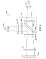
- According to an embodiment of the invention, as illustrated in
Fig. 1 ,fluorometry device 100 includes alight source 105,optical devices 110, amovable platform 115, asample region 120, adetector 125, a focusinglens 130, alight blocker 135, and amotor 140. One example of the general arrangement of these components will now be described. -
Light source 105 emits asource beam 107 that is received by one of theoptical devices 110. For ease of illustration,Fig. 1 shows one optical device onmovable platform 115. However, any number of optical devices can be installed onmovable platform 115. Amotor 140 is also attached tomovable platform 115 with astem 145.Motor 140 is used to move themovable platform 115 to interpose one of theoptical devices 110 into the path of thesource beam 107. Themotor 140 can also move themovable platform 115 to interpose thelight blocker 135 to prevent thesource beam 107 from reaching thesample region 120. - The
optical device 110 receives thesource beam 107 and directs a portion as anexcitation beam 121 through the focusinglens 130 to thesample region 120, where it impinges an array ofsamples 122. Theexcitation beam 121 causes one or more dyes in thesamples 122 to fluoresce and emit light in the form of anemission beam 123. - The
emission beam 123 is received by theoptical device 110 and is then directed by theoptical device 110 to adetector 125. Thedetector 125 generates a data signal that includes information that is representative of the concentration of DNA in thesamples 122. - According to various embodiments, the light source can be LEDs used to provide improved illumination wavelength uniformity, light power output uniformity, and minimal degradation of output over extended periods of time. Further, LEDs operate at relatively low temperatures and require little or no external cooling. In some embodiments, the size of the light emitted from the
light source 105 can be adjusted to be as small as possible to maximize the energy density directed onto thesamples 122. - According to various embodiments, as illustrated in
Fig. 2 ,optical device 210 can include alignment pins 233, abeamsplitter 245, anexcitation filter 250, and anemission filter 260. - According to various embodiments, alignment pins 233 ensure that
optical device 210 can be precisely installed onto themovable platform 115, and thus, allowdevice 100 to easily interchangeoptical devices 110. Different optical devices can be removed and replaced through an access hatch in the instrument case (not shown) fordevice 100. For example, in some embodiments, one or more of theoptical devices 110 attached to the movable platform can be tailored to measure the concentration of DNA based on particular dyes. However, if other dyes are used, alignment pins 233 allowdevice 100 to easily use other optical devices that are tailored to these other dyes. Anoptical device 110 can be removed from themovable platform 115; and a new optical device, such asoptical device 210, can then be installed ontomovable platform 115 usingalignment pins 233 to ensure proper positioning. - The process of aligning
optical device 210 can include positioning the alignment pins 233 into one or more sets of holes (not shown inFig. 2 ) inmovable platform 115. In order to confirm thatoptical device 210 is properly positioned, a fluorescent target that has known characteristic excitation and emission wavelengths, such as a dye exposed to DNA, can be placed in thesample region 120. Theoptical device 210 and/or themovable platform 115 can then be moved, for example in small increments, such that thedetector 125 detects the maximum amount of light emitted from the fluorescent target. The position of theoptical device 210 and/or themovable platform 115 is then recorded. This process can be repeated for any combination of optical devices and fluorescent targets. Alternatively, theoptical device 210 can be aligned using a reference mirror (not shown) and one or more auto-collimators. - Accordingly, alignment pins 233 assist in installing and aligning
optical devices 110 indevice 100. Prior devices required continual re-alignment and disassembly of the device. These prior devices also required mechanical gauges or special tools to align the optical device and to re-assemble the device. In contrast, the optimal alignment position for eachoptical device 110 can be known usingalignment pins 233 and theoptical devices 110 can be easily and quickly substituted without requiring re-alignment. - According to various embodiments,
excitation filter 250 can be used to selectively pass one or more wavelengths ofsource beam 107. Theexcitation filter 250 can be mounted inoptical device 210. The wavelengths passed byexcitation filter 250 can be chosen to block wavelengths shorter than the excitation wavelength of a particular dye exposed to DNA at a particular stage in PCR. In some embodiments, theexcitation filter 250 can block wavelengths shorter than the excitation wavelength of a particular dye exposed to DNA at a particular stage in PCR. Accordingly, theexcitation filter 250 can ensure that theexcitation beam 121 will be close to the characteristic excitation wavelength of a particular dye. - According to the invention each
optical device 210 includes anemission filter 260. Theemission filter 260 can be disposed inoptical device 210 to receive theemission beam 123 before it reaches thedetector 125. Theemission filter 260 can be configured to block light having the excitation wavelength of a particular dye exposed to DNA at a particular stage in PCR and allow wavelengths of the emission wavelength and longer to pass. Accordingly, theemission filter 260 can ensure that theemission beam 123 reaching thedetector 125 will be close to the characteristic emission wavelength of the dye. - According to various embodiments,
beamsplitter 245 can be a dichroic or non-dichroic reflector positioned at 45 degrees. However, depending on the application, thebeamsplitter 245 can be positioned at angles other than 45 degrees. According to various embodiments,beamsplitter 245 can be chosen to transmit wavelengths of light that are shorter than the excitation wavelength of a particular dye exposed to DNA at a particular stage of PCR. Thebeamsplitter 245 can also be chosen to reflect wavelengths that are at, or longer than, the excitation wavelength of a particular dye exposed to DNA at a particular stage of PCR. For example, thebeamsplitter 245 can reflect wavelengths that are shorter than the characteristic wavelength. According to various embodiments,beamsplitter 245 can be a 50-50 partly silvered mirror. - According to various embodiments, as illustrated in
Figs. 3A and3B movable platforms can be configured to provide circular and/or lateral movement.Fig. 3A depicts a rotatablemovable platform 315 such as a turret or carrousel assembly. Rotatablemovable platform 315 can be rotated to move the different optical devices 310a, 310b, 310c, and 310d to receive light from thelight source 305 and to positionlight blocker 330 to block light from reaching the sample. The rotatablemovable platform 315 can be generally circular, or any portion of a circle, so long as it can be rotated and can accommodate multiple attachments. For example, the rotatablemovable platform 315 can accommodate multiple optical devices and a light blocker and can be rotated to position these attachments to receive light from thelight source 305. -
Fig. 3B depicts a linearlymovable platform 365. Linearlymovable platform 365 can be moved linearly to position different optical devices 310a, 310b, 310c, and 310d to receive light from thelight source 305 and to positionlight blocker 335 to block light from reaching the sample. The linearlymovable platform 365 can be any shape, such as rectangular, so long as it can accommodate multiple attachments and can be moved linearly to position the attachments to receive light from thelight source 305. , - According to various embodiments,
movable platforms precision alignment pinholes 375, which are designed to receive alignment pins of an attachment, such as alignment pins 233 ofoptical device 210. As shown inFigs: 3A and3B , theprecision alignment pinholes 375 can be holes formed in themovable platforms light blocker 335. - Now referring back to
Fig. 1 ,sample region 120 provides a location for holding one or more of thesamples 122. For example,sample region 120 can be structured as a tray or bracket that holds one or more vials of thesample 122. -
Sample 122 can be an aqueous suspension of ingredients used for holding one or more "seed" samples of DNA. The aqueous suspension ofsample 122 include selected DNA primer strands, DNA elements, enzymes, and other chemicals. During the PCR process, thesample 122 is thermally cycled, which causes the DNA sample to replicate itself. - According to the
invention detector 125 detects light, such asemission beam 123, emitted from thesample 122. According to various embodiments,detector 125 generates a signal indicating the amount or concentration of DNA present insample 122 based on the light emitted fromsample 122. For example,detector 125 can include one or more processing devices to generate the signal. According to various embodiments,detector 125 can be connected to a processing device that generates the signal. - According to various embodiments,
lens 130 can be optionally included indevice 100 to assist in focusing light, such as theexcitation beam 107, ontosample region 120.Lens 130 can be constructed from known materials and have various refractory properties to focus light ontosample region 120. For example, some embodiments of the invention use a Fresnel lens for thelens 130. - According to the invention,
light blocker 135 allows thedevice 100 to control when sample region is illuminated by thelight source 105.Light blocker 135 can be useful because some dyes become spectrally unstable when they are exposed to changes in temperature, such as from the light source or from PCR. In particular, the peak excitation and emission wavelengths of a dye can "drift" or weaken when the dye is exposed to temperature changes. In prior devices, the light source required a warm-up time to stabilize. During this stabilization period, it is possible to photobleach the sample. Photobleaching weakens the emission spectrum from the dye and can result in the detector sensing an incorrect concentration of DNA. - According to various embodiments,
light blocker 135 can be used indevice 100 to allowlight source 105 to be on continuously. Rather than using a separate mechanical or electronic shutter,device 100 can include alight blocker 135, such as a blocking plate, that is attached to themovable platform 115. Accordingly, themotor 140 can also be used to position themovable platform 115, such that thelight blocker 135 blocks light from thelight source 135. - According to various embodiments,
motor 140 movesmovable platform 115 into various positions to interposeoptical devices 110 into the path ofsource beam 107. As shown inFig. 1 ,motor 140 can be a direct-drive stepper motor. According to various embodiments, as illustrated inFig. 3A ,motor 140 that can be attached tomovable platform 115 by thestem 145 that is mounted into a mountinghole 340. During operation,motor 140 rotates the rotatablemovable platform 315 to position different optical devices 310a - 310d or thelight blocker 335 into and out of the optical path of the source beam. - According to various embodiments,
motor 140 can be any motor that provides linear movement. For example, as shown inFig. 3B ,motor 140 can linearly movemovable platform 365. For ease of illustration, the embodiments shown inFigs. 3A and3B include four optical devices. However, some embodiments ofmovable platforms - According to various examples there is an
optical system 400, as shown inFig. 4 , comprising alight source 405, an optical device 410 (shown generally as the features surrounded by the dotted line), asample region 420, and adetector 425.Light source 405,sample region 420, anddetector 425 can be any of those as described herein. According to various examplesoptical device 410 can comprise an optical device having structures similar to those described herein, such as anexcitation filter 450, abeamsplitter 445, and anemission filter 460.Optical system 400 can also comprise a firstoptical element 424 and a second optical element 424', that may o- may not be included inoptical device 410. - According to various embodiments, first
optical element 424 can comprise a mask, such as a Fresnel mask, that includes a plurality of apertures. Each aperture can be adjusted to reduce non-uniformities in light emitted from the samples insample region 420, which can includesample wells 421. For example, the arrangement of an aperture, such as the size and/or shape of the apertures, can be adjusted. In general, the apertures can be adjusted so light from wells having a similar volume and a similar concentration of sample, and that use a similar die will pass through the mask having a similar light signal, such as a similar relative response. As such, thesignal reaching detector 425 will be an accurate representation of the reaction. - For example, although a first well and a second well of a sample region may contain similar volumes and concentrations of sample material, and may also use similar dyes, the light from each of the first and second wells reaching the detector may not be similar. In various embodiments, a first aperture and a second aperture of the Fresnel mask can be positioned next to the first well and the second well, respectively, of
sample region 420. The arrangement of the first and second apertures can be adjusted so that non-uniformities in the light from the first and second wells that reach the detector can be reduced. - According to various embodiments, the first
optical element 424 can comprise a plurality of lenses with each of the plurality of lenses having a unique numerical aperture (NA). The NA of the lenses, as well as the position of the lenses, can be adjusted to reduce the non-uniformities in light emitted from the samples in the wells of thesample region 420. In some embodiments, the lenses can be molded to have the unique NA. In general, the NA can be adjusted so light from wells having a similar volume and a similar concentration of sample material, and that use a similar die, will pass through the mask having a similar light signal. As such, thesignal reaching detector 425 can be an accurate representation of the reaction. - According to various embodiments, the optical system can further comprise an
additional filter 429, such as a neutral density filter, that can vary the transmission of the emitted sample light. For example;additional filter 429 can vary the transmission based on the position of wells insample region 420. - According to various embodiments,
optical system 410 can further comprise a second optical element 424'. Secondoptical element 424 can comprise a Fresnel mask, a neutral density filter, or a lens having a predetermined NA. Including second optical element 424' aids in reducing non-uniformities in the light fromlight source 410. Second optical element 424' can be positioned to reduce non-uniformities in the light fromlight source 405 before the light reaches thesample region 420. - According to various embodiments, the type of adjustment to
optical elements 424 and 424' can be determined using any of a variety of techniques either separately or in combination. Exemplary techniques include sequential ray trace models, non-sequential ray trace models, radiometric formulae, empirical measurements of light reaching the sample space, and empirical measurements of light reaching the detector. - According to various examples light is emitted from
light source 405 and passes throughexcitation filter 421 and optionally through second optical element 424' before impinging onbeamsplitter 445. A portion of the light impinging onbeamsplitter 445 is directed to the samples insample region 420 where it causes the samples to luminesce. The light emitted from the samples is passed through firstoptical element 424 and optionally throughfurther filter 429. The light is directed through filter 427 and detected bydetector 425. -
Fig. 5a depicts an exemplary spatial response profile when optical systems do not use the optical elements as described herein. As can be seen inFig. 5a , the sample light contains numerous bands of varying intensity. In various examples the varying bands correspond to the non-uniformities in the light emitted from the samples insample region 420 and/or the light emitted fromlight source 405.Fig. 5b depicts an exemplary spatial response profile when optical systems use optical elements as described herein. As can be seen inFig. 5b , the sample light is relatively homogeneous when the optical elements are used. - According to various embodiments, the operation of
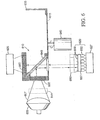
device 100 will now be described with reference toFig. 6 . As shown inFig. 6 , some embodiments of the invention operate by allowing thelight source 605, such as an illumination lamp or LED, to warm to a steady state temperature. Themotor 640 positions thelight blocker 635 attached to themovable platform 615 to block thesource beam 607 from reaching thesample region 620. Thelight blocker 635 can be positioned in front ofsource beam 607 before thelight source 605 is turned on or before thesample 622 is placed in thesample region 620. Thesample 622 is then temperature cycled, using thetemperature controller 627 to initiate the PCR process. At the appropriate time of interest during PCR, the motor 64C moves themovable platform 615 to position the first of a plurality ofoptical devices 610 to receive thesource beam 607. An infra-red (IR)hot mirror filter 641 optionally can be placed between thelight source 605 and theoptical device 610. Further, an optical element (not shown) can be positioned to receive thesource beam 607. - The
source beam 607 goes through the IRhot mirror filter 641 and is received by theexcitation filter 650. The source beam reflects off of thebeamsplitter 645 and is directed to thesample region 620. Anoptical element 655 and/or an additional filter (not shown) can be placed between thebeamsplitter 645 and thesample region 620. Additionally, the multiple samples can be held in asample region 657 that optionally can include welllenses 659 positioned eachsample 622.Well lenses 659 act to focus the light onto thesample 622. Wavelengths of light emitted by thelight source 605 that are shorter than the excitation wavelength of the particular dye exposed to DNA at the appropriate time of PCR are blocked by theexcitation filter 650 and/or transmit through thebeamsplitter 645. Light that impinges thesample 622 is shown as a solid line inFig. 6 with solid arrowheads and can be referred to as the excitation beam. - The excitation beam then causes dyes exposed to DNA in the
sample 622 to emit or fluoresce light. Light emitted from thesample 622, shown as a broken line with hatched arrowheads inFig. 6 , transmits through thewell lens 659, theoptical element lens 655, thebeamsplitter 645, and theemission filter 660. Undesired wavelengths of light emitted from thesample 622 are reflected by thebeamsplitter 645 or are blocked by theemission filter 660. The portion of the emitted light that transmits through thebeamsplitter 645 andemission filter 660 is received by thedetector 625, such as a camera or CCD camera. This transmitted light is shown with a broken line with non-shaded arrowheads inFig. 6 and can be referred to as the emission beam. - According to various embodiments,
sample region 657 that holds thesample 622 can include vials typically formed conically in a plastic unitary tray. The plastic tray can contain a plurality of vials, for example 96 vials in an array of 12 by 8, to hold multiple samples. The tray can be removed from the system for sample preparation. A plastic unitary cover with caps for the vials can rest on or attach to the vials to prevent contamination or evaporation loss. Other systems can be used for this function, such as oil on the top of the sample surface, in which case caps are not needed. If caps are used, they can be transparent to light used by the instrument and can be convex facing upwardly from the sample. A platen (not shown) can optionally rest over the vial caps or, if no caps are used, then directly over the vials. The platen, which can be made of metal, can have an array of holes aligned with the vials. Each hole can have a diameter about the same diameter as the vial top diameter. If there are caps, the platen can have its temperature maintained by a film heater or other device to heat the platen. Heating the platen helps to prevent condensation under the caps without interfering with DNA replication in the vials. For example, the platen can be held at a temperature slightly higher than the highest sample temperature that the thermal cycle reaches. - According to various embodiments, the present teachings provide impinging the excitation beam on
sample region 657 and generating a fluorescent image from the plurality ofsamples 622. This permits thedetector 625 to generate a data signal representative of the DNA in the samples at the particular stage of PCR. - At the next appropriate time of interest in PCR, after the
detector 625 generates the data signal that results from the firstoptical device 610 receiving thesource beam 607, themotor 640 moves themovable platform 615 to position another one of the plurality of optical devices 610 (not shown) to receive thesource beam 607. The other one of the plurality of optical devices receives thesource beam 607 and the process detailed above is repeated. The above processes can be repeated for each appropriate time of interest in PCR. - After the dye:colors of interest are measured, the
movable platform 615 can be moved to position thelight blocker 635 to block thesource beam 607. Thesamples 622 can then be temperature cycled to prepare them for the next detection or until all desired detection has been completed. - Other embodiments of the invention will be apparent to those skilled in the art from consideration of the specification and practice of the invention disclosed herein.
Claims (13)
- A fluorometry device (100) suitable for determining the concentration of species in a biological sample, the device comprising:a light source (105, 605) adapted to provide an excitation beam;a plurality of optical devices (110, 610), each optical device comprising an emission filter (260), an excitation filter (250), and a beam splitter (245), each optical device configured to receive the source beam to produce an excitation beam configured to impinge on an array of samples so as to form an emission beam;a light blocker (135, 635) to block the source beam from reaching the samples of the array of samples;a movable platform (115, 615) for moving each of the plurality of optical devices (110, 610) and the light blocker (135, 635) into the excitation beam; each of the optical devices being installed onto the movable platform and the light blocker being attached to the movable platform;a detector (125, 625) configured to receive the emission beam.
- The fluorometry device (100) of claim 1, wherein the movable platform (115, 615) is suitable for holding the plurality of optical devices (110, 610).
- The fluorometry device (100) of claims 1 or 2, wherein the movable platform (115, 615) comprises a motor to interpose one of the optical devices (110, 610) into a path of the source beam.
- The fluorometry device (100) of claim 2, wherein the movable platform (115, 615) is configured to provide a circular movement or to provide a lateral movement or to provide both a circular movement and a lateral movement.
- The fluorometry device (100) of any one of claims 2 to 4, wherein the optical devices (110, 610) each comprise alignment pins.
- The fluorometry device (100) of claim 5, wherein the movable platform (115, 615) includes alignment pinholes configured to receive the alignment pins of each of the optical devices (110, 610).
- The fluorometry device (100) of claim 1, wherein the light source (105, 605) is an LED.
- The fluorometry device (100) of claim 1, wherein the beamsplitter transmits wavelengths of light shorter than an excitation wavelength a dye in the sample array.
- The fluorometry device (100) of claim 1, wherein the beamsplitter reflects wavelengths at, or longer than, the excitation wavelength a dye in the sample array.
- The fluorometry device (100) of claim 1, wherein the array of samples are disposed in a sample region comprising a tray or bracket that holds one or more vials.
- The fluorometry device (100) of claim 1, wherein the detector (125, 625) is configured to generate a data signal that includes information representative of a concentration of DNA in each sample of the plurality of samples.
- The fluorometry device (100) of claim 1, wherein the excitation filter (250), the emission filter (260), and the beamsplitter provide a first narrow wavelength range for excitation and a second narrow wavelength range for emission.
- A method of fluorometry to monitor a biological sample by using the fluorometry device (100) of claim 1, the method comprising:providing a light blocker (135, 635) to block a source beam from reaching an array of samples and a plurality of optical devices (110, 610), each optical device comprising an emission filter (260), an excitation filter (250), and a beam splitter (245);moving one of the optical devices (110, 610) into a path of the source beam;directing the source beam to the excitation filter (250) and the beam splitter (245) to produce an excitation beam;impinging the excitation beam onto the array of samples disposed in a sample region to produce an emission beam;directing the emission beam to the emission filter (260), to the beam splitter (245); anddirecting the emission onto a detector (125, 625);generating a data signal.
Applications Claiming Priority (5)
| Application Number | Priority Date | Filing Date | Title |
|---|---|---|---|
| US10/758,667 US7295316B2 (en) | 2004-01-14 | 2004-01-14 | Fluorescent detector with automatic changing filters |
| US10/929,320 US7289217B2 (en) | 2004-01-14 | 2004-08-30 | Fluorescent detector with automatic changing filters |
| EP07019705A EP1873512A3 (en) | 2004-01-14 | 2005-01-14 | Apparatus and method for fluorescent detection in biological samples |
| EP10007609A EP2239558A3 (en) | 2004-01-14 | 2005-01-14 | Device for determining concentration of spectrally distinguishable species in a biological sample |
| EP05705833A EP1721146B1 (en) | 2004-01-14 | 2005-01-14 | Apparatus and method for fluorescent detection in biological samples |
Related Parent Applications (6)
| Application Number | Title | Priority Date | Filing Date |
|---|---|---|---|
| EP10007609A Division EP2239558A3 (en) | 2004-01-14 | 2005-01-14 | Device for determining concentration of spectrally distinguishable species in a biological sample |
| EP07019705A Division EP1873512A3 (en) | 2004-01-14 | 2005-01-14 | Apparatus and method for fluorescent detection in biological samples |
| EP05705833A Division EP1721146B1 (en) | 2004-01-14 | 2005-01-14 | Apparatus and method for fluorescent detection in biological samples |
| EP05705833.1 Division | 2005-01-14 | ||
| EP07019705.8 Division | 2007-10-09 | ||
| EP10007609.0 Division | 2010-07-21 |
Publications (3)
| Publication Number | Publication Date |
|---|---|
| EP2315005A2 EP2315005A2 (en) | 2011-04-27 |
| EP2315005A3 EP2315005A3 (en) | 2012-10-03 |
| EP2315005B1 true EP2315005B1 (en) | 2016-01-13 |
Family
ID=34740144
Family Applications (3)
| Application Number | Title | Priority Date | Filing Date |
|---|---|---|---|
| EP07019705A Withdrawn EP1873512A3 (en) | 2004-01-14 | 2005-01-14 | Apparatus and method for fluorescent detection in biological samples |
| EP10013121.8A Active EP2315005B1 (en) | 2004-01-14 | 2005-01-14 | Fluorometry device and method for detection in biological samples |
| EP10007609A Ceased EP2239558A3 (en) | 2004-01-14 | 2005-01-14 | Device for determining concentration of spectrally distinguishable species in a biological sample |
Family Applications Before (1)
| Application Number | Title | Priority Date | Filing Date |
|---|---|---|---|
| EP07019705A Withdrawn EP1873512A3 (en) | 2004-01-14 | 2005-01-14 | Apparatus and method for fluorescent detection in biological samples |
Family Applications After (1)
| Application Number | Title | Priority Date | Filing Date |
|---|---|---|---|
| EP10007609A Ceased EP2239558A3 (en) | 2004-01-14 | 2005-01-14 | Device for determining concentration of spectrally distinguishable species in a biological sample |
Country Status (4)
| Country | Link |
|---|---|
| US (2) | US7295316B2 (en) |
| EP (3) | EP1873512A3 (en) |
| JP (1) | JP2011022166A (en) |
| AT (1) | ATE398769T1 (en) |
Families Citing this family (58)
| Publication number | Priority date | Publication date | Assignee | Title |
|---|---|---|---|---|
| AU6227900A (en) * | 1999-07-21 | 2001-02-13 | Tropix, Inc. | Luminescence detection workstation |
| DE102004015488B4 (en) * | 2004-03-26 | 2008-01-31 | Lavision Biotec Gmbh | Method for reading out by strip-scanning of flat objects with substances that emit fluorescence radiation |
| ATE359500T1 (en) * | 2005-01-18 | 2007-05-15 | Hoffmann La Roche | FLUORESCENCE IMAGING USING TELECENTRICITY |
| JP5065913B2 (en) * | 2005-02-16 | 2012-11-07 | 株式会社日立ハイテクノロジーズ | Refractive index matching in capillary illumination |
| US7507575B2 (en) * | 2005-04-01 | 2009-03-24 | 3M Innovative Properties Company | Multiplex fluorescence detection device having removable optical modules |
| US7709249B2 (en) * | 2005-04-01 | 2010-05-04 | 3M Innovative Properties Company | Multiplex fluorescence detection device having fiber bundle coupling multiple optical modules to a common detector |
| US20070009382A1 (en) * | 2005-07-05 | 2007-01-11 | William Bedingham | Heating element for a rotating multiplex fluorescence detection device |
| US7527763B2 (en) | 2005-07-05 | 2009-05-05 | 3M Innovative Properties Company | Valve control system for a rotating multiplex fluorescence detection device |
| US7630849B2 (en) * | 2005-09-01 | 2009-12-08 | Applied Biosystems, Llc | Method of automated calibration and diagnosis of laboratory instruments |
| WO2007087582A1 (en) | 2006-01-24 | 2007-08-02 | Invitrogen Corporation | Device and methods for quantifying analytes |
| US20090080194A1 (en) * | 2006-02-15 | 2009-03-26 | Li-Cor, Inc. | Fluorescence filtering system and method for molecular imaging |
| EP1989531B1 (en) * | 2006-02-15 | 2022-01-05 | Li-Cor, Inc. | Fluorescence filtering system and method for molecular imaging |
| US20090206278A1 (en) * | 2006-05-08 | 2009-08-20 | Leatech, Llc | Photo-optical-electronic gas, pressure and temperature sensor |
| DE102006036171B4 (en) * | 2006-07-28 | 2008-10-09 | Analytik Jena Ag | Arrangement and method for multichannel fluorescence measurement in PCR samples |
| CN101523198A (en) * | 2006-10-05 | 2009-09-02 | 皇家飞利浦电子股份有限公司 | Methods and systems for detection with front irradiation |
| US7700928B2 (en) * | 2007-01-25 | 2010-04-20 | Etaluma, Inc. | Apparatus and method for interleaving detection of fluorescence and luminescence |
| EP2276849B1 (en) * | 2008-04-24 | 2014-12-03 | 3M Innovative Properties Company | Analysis of nucleic acid amplification curves using wavelet transformation |
| US20100124766A1 (en) | 2008-11-14 | 2010-05-20 | Life Technologies Corporation | Apparatus and Method for Segmented Thermal Cycler |
| KR101165720B1 (en) * | 2008-11-18 | 2012-07-18 | 한국전자통신연구원 | Portable biophotonic sensor measurement apparatus and the measuring method of the same |
| US8448322B2 (en) * | 2009-01-24 | 2013-05-28 | Thomas Leen | Method and system for replacing the water cooled laser in a microplate reader |
| US8934098B2 (en) * | 2009-08-31 | 2015-01-13 | Life Technologies Corporation | Fast-indexing filter wheel and method of use |
| EP2301666B1 (en) | 2009-09-09 | 2021-06-30 | Cole-Parmer Ltd. | Optical system for multiple reactions |
| WO2011112465A1 (en) | 2010-03-06 | 2011-09-15 | Illumina, Inc. | Systems, methods, and apparatuses for detecting optical signals from a sample |
| WO2012059784A1 (en) | 2010-11-03 | 2012-05-10 | Reametrix Inc | Method and device for fluorescent measurement of samples |
| WO2012082464A2 (en) | 2010-12-14 | 2012-06-21 | Life Technologies Corporation | Systems and methods for run-time sequencing run quality monitoring |
| IT1403792B1 (en) * | 2010-12-30 | 2013-10-31 | St Microelectronics Srl | ANALYZER FOR BIOCHEMICAL ANALYSIS AND METHOD FOR DETERMINING CONCENTRATIONS OF FLUORESCENT SUBSTANCES IN A SOLUTION |
| US9481906B2 (en) | 2011-02-04 | 2016-11-01 | Universal Bio Research Co., Ltd. | Automatic light measurement device with a movable mount for coupling with multiple reaction containers |
| US9134241B2 (en) | 2011-04-11 | 2015-09-15 | Li-Cor, Inc. | Differential scan imaging systems and methods |
| US9737891B2 (en) | 2011-06-01 | 2017-08-22 | Streck, Inc. | Rapid thermocycler system for rapid amplification of nucleic acids and related methods |
| US8421037B2 (en) * | 2011-06-10 | 2013-04-16 | Rockwell Automation Technologies, Inc. | System and method for reduction of optical noise |
| US8480246B2 (en) | 2011-06-10 | 2013-07-09 | Rockwell Automation Technologies, Inc. | System and method for reduction of optical noise |
| DE102011079942B4 (en) * | 2011-07-27 | 2016-12-15 | Leica Microsystems Cms Gmbh | Microscope illumination method and microscope |
| CN104105957B (en) | 2011-09-30 | 2018-06-19 | 生命科技公司 | For the optical system and method for bioanalysis |
| JP6227536B2 (en) * | 2011-09-30 | 2017-11-08 | ライフ テクノロジーズ コーポレーション | Systems and methods for biological analysis |
| US9618449B2 (en) | 2012-02-03 | 2017-04-11 | The Trustees Of Columbia University In The City Of New York | Optical analysis of emissions from stimulated liquids |
| EP2893323A1 (en) * | 2012-05-09 | 2015-07-15 | Life Technologies Corporation | Systems and method for fluorescence imaging |
| EP2883039A1 (en) | 2012-08-10 | 2015-06-17 | Streck Inc. | Real-time optical system for polymerase chain reaction |
| CN102830224B (en) * | 2012-08-28 | 2014-09-24 | 天津市先石光学技术有限公司 | Optical path switching mechanism for homogeneous luminescent immunodetection |
| US8858886B1 (en) | 2013-05-08 | 2014-10-14 | Agilent Technologies, Inc. | Scanning system with interchangeable optical cartridges for fluorescence measurements |
| EP3014251A1 (en) | 2013-06-28 | 2016-05-04 | Streck Inc. | Devices for real-time polymerase chain reaction |
| DE102014108143A1 (en) * | 2014-06-10 | 2015-12-10 | Kist Europe-Korea Institute of Science and Technologie Europe Forschungsgesellschaft mbh | An optical system for detecting fluorescent or luminescent signals of at least two samples |
| US9541750B2 (en) | 2014-06-23 | 2017-01-10 | Li-Cor, Inc. | Telecentric, wide-field fluorescence scanning systems and methods |
| JP6416530B2 (en) * | 2014-07-24 | 2018-10-31 | 株式会社日立ハイテクノロジーズ | Fluorescence observation apparatus and fluorescence observation method |
| DE102015011429B9 (en) * | 2015-09-01 | 2020-01-09 | Carl Zeiss Meditec Ag | Optical filter system and fluorescence observation system |
| KR101754108B1 (en) | 2015-10-02 | 2017-07-05 | 강태경 | System for measuring vignetting caused by camera lenz |
| CN108700520B (en) * | 2016-02-26 | 2021-12-07 | 辛格科技公司 | Method and apparatus for high throughput imaging |
| CN107817227B (en) | 2016-09-12 | 2020-08-28 | 台达电子国际(新加坡)私人有限公司 | Fluorescence detection device |
| SG10201609334WA (en) | 2016-11-08 | 2018-06-28 | Delta Electronics Intl Singapore Pte Ltd | Multi-Channel Fluorescence Detection Device |
| JP7356351B2 (en) | 2016-12-12 | 2023-10-04 | エクセラ・バイオサイエンシーズ・インコーポレイテッド | Methods and systems for screening using microcapillary arrays |
| US20180364150A1 (en) * | 2017-06-14 | 2018-12-20 | Cypress Semiconductor Corporation | Optical monitoring of target characteristics |
| SG10201801853WA (en) | 2018-03-02 | 2019-10-30 | Delta Electronics Int’L Singapore Pte Ltd | Portable multi-color fluorescence detection device |
| JP7098146B2 (en) * | 2018-07-05 | 2022-07-11 | 株式会社Iddk | Microscopic observation device, fluorescence detector and microscopic observation method |
| JP7022670B2 (en) * | 2018-09-10 | 2022-02-18 | 株式会社日立ハイテク | Spectrum calibration device and spectrum calibration method |
| WO2021010817A1 (en) | 2019-07-12 | 2021-01-21 | Sime Darby Plantation Intellectual Property Sdn. Bhd. | Apparatus to measure ripeness of oil palm fruitlets via real-time chlorophyll content measurement |
| TWI722785B (en) | 2020-01-31 | 2021-03-21 | 台達電子工業股份有限公司 | Optical calibration tool |
| CN112161927A (en) * | 2020-09-11 | 2021-01-01 | 广州万孚生物技术股份有限公司 | In-vitro diagnosis and analysis system and optical detection device |
| CN112326610A (en) * | 2020-10-28 | 2021-02-05 | 瑞莱生物科技江苏有限公司 | Quantitative fluorescence detection optical device |
| TW202221310A (en) * | 2020-11-27 | 2022-06-01 | 緯創資通股份有限公司 | Detection device and method thereof |
Citations (2)
| Publication number | Priority date | Publication date | Assignee | Title |
|---|---|---|---|---|
| JPH10206745A (en) * | 1997-01-22 | 1998-08-07 | Olympus Optical Co Ltd | Scanning optical microscope |
| WO2003067230A1 (en) * | 2002-02-07 | 2003-08-14 | Fuji Electric Holdings Co.,Ltd. | Fluorescent image measuring method and device |
Family Cites Families (36)
| Publication number | Priority date | Publication date | Assignee | Title |
|---|---|---|---|---|
| CH567733A5 (en) * | 1973-04-02 | 1975-10-15 | Leitz Ernst Gmbh | |
| JP2749069B2 (en) * | 1988-04-26 | 1998-05-13 | オリンパス光学工業株式会社 | Fluorescence microscope equipment |
| US4972258A (en) * | 1989-07-31 | 1990-11-20 | E. I. Du Pont De Nemours And Company | Scanning laser microscope system and methods of use |
| EP0588931A4 (en) * | 1991-06-13 | 1994-06-22 | Abbott Lab | Automated specimen analyzing apparatus and method |
| US5528050A (en) * | 1995-07-24 | 1996-06-18 | Molecular Dynamics, Inc. | Compact scan head with multiple scanning modalities |
| AU4920297A (en) * | 1996-10-25 | 1998-05-15 | Applied Imaging, Inc. | Multifluor-fluorescence in situ hybridization (m-fish) imaging techniques using multiple multiband filters with image registration |
| JP3697007B2 (en) | 1997-02-10 | 2005-09-21 | 浜松ホトニクス株式会社 | Multi titer plate analyzer |
| US6534308B1 (en) * | 1997-03-27 | 2003-03-18 | Oncosis, Llc | Method and apparatus for selectively targeting specific cells within a mixed cell population |
| US6259807B1 (en) * | 1997-05-14 | 2001-07-10 | Applied Imaging Corp. | Identification of objects of interest using multiple illumination schemes and finding overlap of features in corresponding multiple images |
| JP3877380B2 (en) * | 1997-06-18 | 2007-02-07 | オリンパス株式会社 | Optical microscope |
| US5943129A (en) * | 1997-08-07 | 1999-08-24 | Cambridge Research & Instrumentation Inc. | Fluorescence imaging system |
| US6043506A (en) * | 1997-08-13 | 2000-03-28 | Bio-Rad Laboratories, Inc. | Multi parameter scanner |
| JPH11218690A (en) * | 1998-02-04 | 1999-08-10 | Olympus Optical Co Ltd | Microscope with vertical fluorescent illuminating optical system |
| US6818437B1 (en) * | 1998-05-16 | 2004-11-16 | Applera Corporation | Instrument for monitoring polymerase chain reaction of DNA |
| EP1978351B1 (en) | 1998-05-16 | 2011-11-30 | Life Technologies Corporation | Instrument for monitoring polymerase chain reaction of dna |
| AU5667499A (en) * | 1998-07-27 | 2000-02-21 | Ljl Biosystems, Inc. | Apparatus and methods for identifying quenching effects in luminescence assays |
| FI982005A (en) | 1998-09-17 | 2000-03-18 | Wallac Oy | Sample imaging device |
| AT3085U1 (en) * | 1998-10-23 | 1999-09-27 | Tecan Austria Gmbh | MEASURING HEAD |
| US7410793B2 (en) * | 1999-05-17 | 2008-08-12 | Applera Corporation | Optical instrument including excitation source |
| WO2000079326A1 (en) * | 1999-06-18 | 2000-12-28 | Genomic Solutions Inc. | An automated, ccd-based microarray imaging system |
| AU7131900A (en) * | 1999-06-21 | 2001-01-09 | Cellomics, Inc. | A system for cell-based screening |
| AU6227900A (en) * | 1999-07-21 | 2001-02-13 | Tropix, Inc. | Luminescence detection workstation |
| JP2001083090A (en) | 1999-09-10 | 2001-03-30 | Fuji Photo Film Co Ltd | Excitation light source for micro titer plate |
| US6645777B1 (en) * | 1999-11-05 | 2003-11-11 | The Board Of Governors For Higher Education, State Of Rhode Island And Providence Plantation | Tapered tubular optical waveguide probe for magnetic focusing immunosensors |
| JP4846152B2 (en) * | 1999-11-12 | 2011-12-28 | イー・アイ・デュポン・ドウ・ヌムール・アンド・カンパニー | Fluorescence measuring instrument with low heat source |
| US6333501B1 (en) * | 2000-01-27 | 2001-12-25 | Perkin-Elmer Corporation | Methods, apparatus, and articles of manufacture for performing spectral calibration |
| TWI220926B (en) * | 2000-03-24 | 2004-09-11 | Ind Tech Res Inst | Sieving apparatus for a bio-chip |
| JP2002014044A (en) | 2000-06-29 | 2002-01-18 | Nikon Corp | Fluorometric apparatus |
| JP3576523B2 (en) * | 2000-12-26 | 2004-10-13 | オリンパス株式会社 | Fluorescence luminance measurement method and apparatus |
| JP3999479B2 (en) * | 2001-07-10 | 2007-10-31 | オリンパス株式会社 | Optical device |
| US6744502B2 (en) * | 2001-09-28 | 2004-06-01 | Pe Corporation (Ny) | Shaped illumination geometry and intensity using a diffractive optical element |
| US20050227231A1 (en) * | 2001-10-04 | 2005-10-13 | Dimitri Tcherkassov | Device for sequencing nucleic acid molecules |
| US6982166B2 (en) * | 2002-05-16 | 2006-01-03 | Applera Corporation | Lens assembly for biological testing |
| JP2005526252A (en) * | 2002-05-17 | 2005-09-02 | アプレラ コーポレイション | Optical instrument with excitation source |
| ATE338945T1 (en) | 2002-10-17 | 2006-09-15 | Direvo Biotech Ag | FLUORIMETRIC MULTI-PARAMETER ANALYSIS IN A PARALLEL MULTI-FOCUS ARRANGEMENT |
| US7050224B2 (en) * | 2003-11-07 | 2006-05-23 | Olympus Corporation | Fluorescence observing apparatus |
-
2004
- 2004-01-14 US US10/758,667 patent/US7295316B2/en active Active
- 2004-08-30 US US10/929,320 patent/US7289217B2/en active Active
-
2005
- 2005-01-14 EP EP07019705A patent/EP1873512A3/en not_active Withdrawn
- 2005-01-14 EP EP10013121.8A patent/EP2315005B1/en active Active
- 2005-01-14 AT AT05705833T patent/ATE398769T1/en not_active IP Right Cessation
- 2005-01-14 EP EP10007609A patent/EP2239558A3/en not_active Ceased
-
2010
- 2010-11-05 JP JP2010249225A patent/JP2011022166A/en active Pending
Patent Citations (2)
| Publication number | Priority date | Publication date | Assignee | Title |
|---|---|---|---|---|
| JPH10206745A (en) * | 1997-01-22 | 1998-08-07 | Olympus Optical Co Ltd | Scanning optical microscope |
| WO2003067230A1 (en) * | 2002-02-07 | 2003-08-14 | Fuji Electric Holdings Co.,Ltd. | Fluorescent image measuring method and device |
Also Published As
| Publication number | Publication date |
|---|---|
| EP1873512A3 (en) | 2008-12-03 |
| US20050151972A1 (en) | 2005-07-14 |
| US7289217B2 (en) | 2007-10-30 |
| ATE398769T1 (en) | 2008-07-15 |
| EP2239558A2 (en) | 2010-10-13 |
| EP2315005A3 (en) | 2012-10-03 |
| EP2315005A2 (en) | 2011-04-27 |
| EP1873512A2 (en) | 2008-01-02 |
| JP2011022166A (en) | 2011-02-03 |
| US20050190366A1 (en) | 2005-09-01 |
| EP2239558A3 (en) | 2010-12-29 |
| US7295316B2 (en) | 2007-11-13 |
Similar Documents
| Publication | Publication Date | Title |
|---|---|---|
| EP2315005B1 (en) | Fluorometry device and method for detection in biological samples | |
| EP2376896B1 (en) | Optical system for chemical and/or biochemical reactions | |
| US6852986B1 (en) | Fluorometer with low heat-generating light source | |
| EP1228357B1 (en) | Fluorometer with low heat-generating light source | |
| EP3093649B1 (en) | A combination of a reaction apparatus and an optical instrument monitoring dna polymerase chain reactions | |
| EP2419743B1 (en) | OPTICAL DETECTION SYSTEM FOR MONITORING rtPCR REACTION | |
| EP2674745B1 (en) | Instrument for detecting and measuring fluorescence | |
| EP1721146B1 (en) | Apparatus and method for fluorescent detection in biological samples | |
| US20070098594A1 (en) | Analytical multi-spectral optical detection system | |
| JP5623385B2 (en) | Reaction optical measuring apparatus and measuring method thereof | |
| US20080253409A1 (en) | Multi-Channel Bio-Chip Scanner | |
| EP1921440A2 (en) | Fluorometer with low heat-generating light source |
Legal Events
| Date | Code | Title | Description |
|---|---|---|---|
| PUAI | Public reference made under article 153(3) epc to a published international application that has entered the european phase |
Free format text: ORIGINAL CODE: 0009012 |
|
| AC | Divisional application: reference to earlier application |
Ref document number: 2239558 Country of ref document: EP Kind code of ref document: P Ref document number: 1873512 Country of ref document: EP Kind code of ref document: P Ref document number: 1721146 Country of ref document: EP Kind code of ref document: P |
|
| AK | Designated contracting states |
Kind code of ref document: A2 Designated state(s): AT BE BG CH CY CZ DE DK EE ES FI FR GB GR HU IE IS IT LI LT LU MC NL PL PT RO SE SI SK TR |
|
| RIC1 | Information provided on ipc code assigned before grant |
Ipc: G01N 21/64 20060101AFI20120514BHEP Ipc: G01N 21/25 20060101ALI20120514BHEP Ipc: C12Q 1/68 20060101ALI20120514BHEP |
|
| PUAL | Search report despatched |
Free format text: ORIGINAL CODE: 0009013 |
|
| AK | Designated contracting states |
Kind code of ref document: A3 Designated state(s): AT BE BG CH CY CZ DE DK EE ES FI FR GB GR HU IE IS IT LI LT LU MC NL PL PT RO SE SI SK TR |
|
| RIC1 | Information provided on ipc code assigned before grant |
Ipc: G01N 21/64 20060101AFI20120828BHEP Ipc: C12Q 1/68 20060101ALI20120828BHEP Ipc: G01N 21/25 20060101ALI20120828BHEP |
|
| 17P | Request for examination filed |
Effective date: 20130403 |
|
| 17Q | First examination report despatched |
Effective date: 20140407 |
|
| GRAP | Despatch of communication of intention to grant a patent |
Free format text: ORIGINAL CODE: EPIDOSNIGR1 |
|
| GRAS | Grant fee paid |
Free format text: ORIGINAL CODE: EPIDOSNIGR3 |
|
| INTG | Intention to grant announced |
Effective date: 20151113 |
|
| GRAA | (expected) grant |
Free format text: ORIGINAL CODE: 0009210 |
|
| AC | Divisional application: reference to earlier application |
Ref document number: 1873512 Country of ref document: EP Kind code of ref document: P Ref document number: 2239558 Country of ref document: EP Kind code of ref document: P Ref document number: 1721146 Country of ref document: EP Kind code of ref document: P |
|
| AK | Designated contracting states |
Kind code of ref document: B1 Designated state(s): AT BE BG CH CY CZ DE DK EE ES FI FR GB GR HU IE IS IT LI LT LU MC NL PL PT RO SE SI SK TR |
|
| REG | Reference to a national code |
Ref country code: GB Ref legal event code: FG4D |
|
| REG | Reference to a national code |
Ref country code: CH Ref legal event code: EP |
|
| REG | Reference to a national code |
Ref country code: FR Ref legal event code: PLFP Year of fee payment: 12 |
|
| REG | Reference to a national code |
Ref country code: CH Ref legal event code: NV Representative=s name: REUTELER AND CIE S.A., CH |
|
| REG | Reference to a national code |
Ref country code: IE Ref legal event code: FG4D |
|
| REG | Reference to a national code |
Ref country code: AT Ref legal event code: REF Ref document number: 770859 Country of ref document: AT Kind code of ref document: T Effective date: 20160215 |
|
| REG | Reference to a national code |
Ref country code: DE Ref legal event code: R096 Ref document number: 602005048312 Country of ref document: DE |
|
| REG | Reference to a national code |
Ref country code: LT Ref legal event code: MG4D |
|
| REG | Reference to a national code |
Ref country code: NL Ref legal event code: MP Effective date: 20160113 |
|
| PG25 | Lapsed in a contracting state [announced via postgrant information from national office to epo] |
Ref country code: BE Free format text: LAPSE BECAUSE OF NON-PAYMENT OF DUE FEES Effective date: 20160131 |
|
| REG | Reference to a national code |
Ref country code: AT Ref legal event code: MK05 Ref document number: 770859 Country of ref document: AT Kind code of ref document: T Effective date: 20160113 |
|
| PG25 | Lapsed in a contracting state [announced via postgrant information from national office to epo] |
Ref country code: NL Free format text: LAPSE BECAUSE OF FAILURE TO SUBMIT A TRANSLATION OF THE DESCRIPTION OR TO PAY THE FEE WITHIN THE PRESCRIBED TIME-LIMIT Effective date: 20160113 |
|
| PG25 | Lapsed in a contracting state [announced via postgrant information from national office to epo] |
Ref country code: IT Free format text: LAPSE BECAUSE OF FAILURE TO SUBMIT A TRANSLATION OF THE DESCRIPTION OR TO PAY THE FEE WITHIN THE PRESCRIBED TIME-LIMIT Effective date: 20160113 Ref country code: ES Free format text: LAPSE BECAUSE OF FAILURE TO SUBMIT A TRANSLATION OF THE DESCRIPTION OR TO PAY THE FEE WITHIN THE PRESCRIBED TIME-LIMIT Effective date: 20160113 Ref country code: FI Free format text: LAPSE BECAUSE OF FAILURE TO SUBMIT A TRANSLATION OF THE DESCRIPTION OR TO PAY THE FEE WITHIN THE PRESCRIBED TIME-LIMIT Effective date: 20160113 Ref country code: GR Free format text: LAPSE BECAUSE OF FAILURE TO SUBMIT A TRANSLATION OF THE DESCRIPTION OR TO PAY THE FEE WITHIN THE PRESCRIBED TIME-LIMIT Effective date: 20160414 |
|
| PG25 | Lapsed in a contracting state [announced via postgrant information from national office to epo] |
Ref country code: LT Free format text: LAPSE BECAUSE OF FAILURE TO SUBMIT A TRANSLATION OF THE DESCRIPTION OR TO PAY THE FEE WITHIN THE PRESCRIBED TIME-LIMIT Effective date: 20160113 Ref country code: PL Free format text: LAPSE BECAUSE OF FAILURE TO SUBMIT A TRANSLATION OF THE DESCRIPTION OR TO PAY THE FEE WITHIN THE PRESCRIBED TIME-LIMIT Effective date: 20160113 Ref country code: AT Free format text: LAPSE BECAUSE OF FAILURE TO SUBMIT A TRANSLATION OF THE DESCRIPTION OR TO PAY THE FEE WITHIN THE PRESCRIBED TIME-LIMIT Effective date: 20160113 Ref country code: SE Free format text: LAPSE BECAUSE OF FAILURE TO SUBMIT A TRANSLATION OF THE DESCRIPTION OR TO PAY THE FEE WITHIN THE PRESCRIBED TIME-LIMIT Effective date: 20160113 Ref country code: PT Free format text: LAPSE BECAUSE OF FAILURE TO SUBMIT A TRANSLATION OF THE DESCRIPTION OR TO PAY THE FEE WITHIN THE PRESCRIBED TIME-LIMIT Effective date: 20160513 Ref country code: IS Free format text: LAPSE BECAUSE OF FAILURE TO SUBMIT A TRANSLATION OF THE DESCRIPTION OR TO PAY THE FEE WITHIN THE PRESCRIBED TIME-LIMIT Effective date: 20160513 |
|
| REG | Reference to a national code |
Ref country code: DE Ref legal event code: R097 Ref document number: 602005048312 Country of ref document: DE |
|
| PG25 | Lapsed in a contracting state [announced via postgrant information from national office to epo] |
Ref country code: EE Free format text: LAPSE BECAUSE OF FAILURE TO SUBMIT A TRANSLATION OF THE DESCRIPTION OR TO PAY THE FEE WITHIN THE PRESCRIBED TIME-LIMIT Effective date: 20160113 Ref country code: DK Free format text: LAPSE BECAUSE OF FAILURE TO SUBMIT A TRANSLATION OF THE DESCRIPTION OR TO PAY THE FEE WITHIN THE PRESCRIBED TIME-LIMIT Effective date: 20160113 Ref country code: MC Free format text: LAPSE BECAUSE OF FAILURE TO SUBMIT A TRANSLATION OF THE DESCRIPTION OR TO PAY THE FEE WITHIN THE PRESCRIBED TIME-LIMIT Effective date: 20160113 |
|
| REG | Reference to a national code |
Ref country code: IE Ref legal event code: MM4A |
|
| PLBE | No opposition filed within time limit |
Free format text: ORIGINAL CODE: 0009261 |
|
| STAA | Information on the status of an ep patent application or granted ep patent |
Free format text: STATUS: NO OPPOSITION FILED WITHIN TIME LIMIT |
|
| RAP2 | Party data changed (patent owner data changed or rights of a patent transferred) |
Owner name: LIFE TECHNOLOGIES CORPORATION |
|
| PG25 | Lapsed in a contracting state [announced via postgrant information from national office to epo] |
Ref country code: RO Free format text: LAPSE BECAUSE OF FAILURE TO SUBMIT A TRANSLATION OF THE DESCRIPTION OR TO PAY THE FEE WITHIN THE PRESCRIBED TIME-LIMIT Effective date: 20160113 Ref country code: CZ Free format text: LAPSE BECAUSE OF FAILURE TO SUBMIT A TRANSLATION OF THE DESCRIPTION OR TO PAY THE FEE WITHIN THE PRESCRIBED TIME-LIMIT Effective date: 20160113 Ref country code: SK Free format text: LAPSE BECAUSE OF FAILURE TO SUBMIT A TRANSLATION OF THE DESCRIPTION OR TO PAY THE FEE WITHIN THE PRESCRIBED TIME-LIMIT Effective date: 20160113 |
|
| REG | Reference to a national code |
Ref country code: FR Ref legal event code: PLFP Year of fee payment: 13 |
|
| 26N | No opposition filed |
Effective date: 20161014 |
|
| PG25 | Lapsed in a contracting state [announced via postgrant information from national office to epo] |
Ref country code: BE Free format text: LAPSE BECAUSE OF FAILURE TO SUBMIT A TRANSLATION OF THE DESCRIPTION OR TO PAY THE FEE WITHIN THE PRESCRIBED TIME-LIMIT Effective date: 20160113 |
|
| PG25 | Lapsed in a contracting state [announced via postgrant information from national office to epo] |
Ref country code: IE Free format text: LAPSE BECAUSE OF NON-PAYMENT OF DUE FEES Effective date: 20160114 |
|
| PG25 | Lapsed in a contracting state [announced via postgrant information from national office to epo] |
Ref country code: SI Free format text: LAPSE BECAUSE OF FAILURE TO SUBMIT A TRANSLATION OF THE DESCRIPTION OR TO PAY THE FEE WITHIN THE PRESCRIBED TIME-LIMIT Effective date: 20160113 Ref country code: BG Free format text: LAPSE BECAUSE OF FAILURE TO SUBMIT A TRANSLATION OF THE DESCRIPTION OR TO PAY THE FEE WITHIN THE PRESCRIBED TIME-LIMIT Effective date: 20160413 |
|
| REG | Reference to a national code |
Ref country code: FR Ref legal event code: PLFP Year of fee payment: 14 |
|
| PGFP | Annual fee paid to national office [announced via postgrant information from national office to epo] |
Ref country code: CH Payment date: 20180115 Year of fee payment: 14 |
|
| PG25 | Lapsed in a contracting state [announced via postgrant information from national office to epo] |
Ref country code: HU Free format text: LAPSE BECAUSE OF FAILURE TO SUBMIT A TRANSLATION OF THE DESCRIPTION OR TO PAY THE FEE WITHIN THE PRESCRIBED TIME-LIMIT; INVALID AB INITIO Effective date: 20050114 Ref country code: CY Free format text: LAPSE BECAUSE OF FAILURE TO SUBMIT A TRANSLATION OF THE DESCRIPTION OR TO PAY THE FEE WITHIN THE PRESCRIBED TIME-LIMIT Effective date: 20160113 |
|
| PG25 | Lapsed in a contracting state [announced via postgrant information from national office to epo] |
Ref country code: TR Free format text: LAPSE BECAUSE OF FAILURE TO SUBMIT A TRANSLATION OF THE DESCRIPTION OR TO PAY THE FEE WITHIN THE PRESCRIBED TIME-LIMIT Effective date: 20160113 Ref country code: LU Free format text: LAPSE BECAUSE OF NON-PAYMENT OF DUE FEES Effective date: 20160114 |
|
| REG | Reference to a national code |
Ref country code: CH Ref legal event code: PL |
|
| PG25 | Lapsed in a contracting state [announced via postgrant information from national office to epo] |
Ref country code: LI Free format text: LAPSE BECAUSE OF NON-PAYMENT OF DUE FEES Effective date: 20190131 Ref country code: CH Free format text: LAPSE BECAUSE OF NON-PAYMENT OF DUE FEES Effective date: 20190131 |
|
| PGFP | Annual fee paid to national office [announced via postgrant information from national office to epo] |
Ref country code: FR Payment date: 20230125 Year of fee payment: 19 |
|
| PGFP | Annual fee paid to national office [announced via postgrant information from national office to epo] |
Ref country code: GB Payment date: 20230117 Year of fee payment: 19 Ref country code: DE Payment date: 20230103 Year of fee payment: 19 |