EP2314909B1 - Beleuchtungsvorrichtung - Google Patents
Beleuchtungsvorrichtung Download PDFInfo
- Publication number
- EP2314909B1 EP2314909B1 EP09173750A EP09173750A EP2314909B1 EP 2314909 B1 EP2314909 B1 EP 2314909B1 EP 09173750 A EP09173750 A EP 09173750A EP 09173750 A EP09173750 A EP 09173750A EP 2314909 B1 EP2314909 B1 EP 2314909B1
- Authority
- EP
- European Patent Office
- Prior art keywords
- spotlight
- respect
- piece
- lighting device
- pivot axis
- Prior art date
- Legal status (The legal status is an assumption and is not a legal conclusion. Google has not performed a legal analysis and makes no representation as to the accuracy of the status listed.)
- Not-in-force
Links
- 230000007246 mechanism Effects 0.000 description 9
- 238000004519 manufacturing process Methods 0.000 description 2
- 230000006835 compression Effects 0.000 description 1
- 238000007906 compression Methods 0.000 description 1
- 238000010348 incorporation Methods 0.000 description 1
- 230000000284 resting effect Effects 0.000 description 1
Images


Classifications
-
- F—MECHANICAL ENGINEERING; LIGHTING; HEATING; WEAPONS; BLASTING
- F21—LIGHTING
- F21S—NON-PORTABLE LIGHTING DEVICES; SYSTEMS THEREOF; VEHICLE LIGHTING DEVICES SPECIALLY ADAPTED FOR VEHICLE EXTERIORS
- F21S8/00—Lighting devices intended for fixed installation
- F21S8/02—Lighting devices intended for fixed installation of recess-mounted type, e.g. downlighters
-
- F—MECHANICAL ENGINEERING; LIGHTING; HEATING; WEAPONS; BLASTING
- F21—LIGHTING
- F21V—FUNCTIONAL FEATURES OR DETAILS OF LIGHTING DEVICES OR SYSTEMS THEREOF; STRUCTURAL COMBINATIONS OF LIGHTING DEVICES WITH OTHER ARTICLES, NOT OTHERWISE PROVIDED FOR
- F21V21/00—Supporting, suspending, or attaching arrangements for lighting devices; Hand grips
- F21V21/14—Adjustable mountings
- F21V21/30—Pivoted housings or frames
-
- F—MECHANICAL ENGINEERING; LIGHTING; HEATING; WEAPONS; BLASTING
- F21—LIGHTING
- F21V—FUNCTIONAL FEATURES OR DETAILS OF LIGHTING DEVICES OR SYSTEMS THEREOF; STRUCTURAL COMBINATIONS OF LIGHTING DEVICES WITH OTHER ARTICLES, NOT OTHERWISE PROVIDED FOR
- F21V21/00—Supporting, suspending, or attaching arrangements for lighting devices; Hand grips
- F21V21/02—Wall, ceiling, or floor bases; Fixing pendants or arms to the bases
- F21V21/04—Recessed bases
Definitions
- the present invention relates to a lighting device, especially of the recessed type.
- Recessed lighting devices that are generally installed in ceilings and that allow to orientate a spotlight in the desired direction are known. Thanks to this feature, it is possible to address the beam of light of the lighting device towards a determined area without having to dismount said device.
- a problem related with this type of lighting devices is that the position of the spotlight can vary once it has been arranged in the desired orientation, due to its own weight, to the force of compression or traction exerted by power supply wirings or to an impact or contact with an external element.
- a lighting device comprising a spotlight linked to a support and that rotates with respect to a first pivot axis and with respect to a second axis.
- the device comprises a pair of actuation mechanisms.
- the first mechanism is actuated by means of a screwdriver and rotates the spotlight with respect to the first axis.
- the second mechanism is also actuated by means of a screwdriver and rotates the spotlight with respect to the second axis.
- Said lighting device allows the rotational and angular orientation of the spotlight and it allows to fix it in the desired position, as when the actuation mechanisms are not actuated the spotlight remains locked and does not move. Nevertheless, this device has the drawback that the actuation of the mechanisms is slow, as it is necessary to rotate each of them by means of a screwdriver. Likewise, the presence of said actuation mechanisms (a screw mechanism and a gear pinion-tooth wheel mechanism) increases the manufacturing cost and the complexity of the lighting device.
- Another lighting device known in the art comprises a spotlight linked to a support and rotating with respect to a first pivot axis and with respect to a second axis.
- This lighting device comprises a locking device that allows to fix the position of the spotlight.
- the locking device comprises a pair of brake elements.
- Each brake element consists of a screw, a lateral wing of the spotlight and a break shoe screwed to the free end of the screw. The screw passes through a ring, with respect to which the spotlight pivots, and through a slot present in the lateral wing.
- the break shoe slides towards a support surface, until contacting the same, so that if the screw continues being tightened, the break shoe exerts enough pressure on the support and avoids the spotlight for being rotational orientated.
- the break shoe presses a spring arranged around the screw and situated between a part of said break shoe and the slot present in the lateral wing of the spotlight. Said spring exerts a pressure on said wing, so that the longitudinal position of the screw inside the slot is blocked, thus avoiding the pivoting of the spotlight.
- Said lighting device has the drawback of requiring the actuation of two screws to fix the position of the spotlight. Furthermore, the locking system of the pivoting movement of the spotlight is not effective, as the pressure of the spring on the wing does not allow to completely fix the position of the spotlight. Likewise, said system makes necessary to conform at least a pair of lateral wings in the spotlight, thus complicating its manufacturing and increasing its volume.
- US 2009/027900 A1 describes a positionable outdoor lighting comprising the features of the preamble of Claim 1.
- the object of the present invention is to overcome the drawbacks that the devices know in the art have, by providing a lighting device according to Claim 1.
- the screw is linked to the spotlight, to the first piece and to the second piece, so that when the screw is tightened the first piece presses a part of the pivot axis of the spotlight against the second piece, thus locking the rotation of the spotlight with respect to said pivot axis, and the second piece presses a part of the support, thus locking the rotation of the spotlight with respect to the second axis.
- the locking means act directly on the pivot axis of the spotlight it is possible to apply the retaining force in a more effective way and without intermediate elements, by completely locking the pivoting movement of said spotlight.
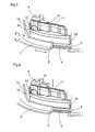
- Figure 1 an exploded view of a lighting device according to the present invention can be seen.
- the device basically comprises a spotlight 1, a rotatable ring 2 and a ring-shaped support 3 which is intended to be fixed to the ceiling or to any similar element.
- the rotatable ring 2 can rotate with respect to the support 3, and the spotlight 1 is articulated with respect to the rotatable ring 2, so that it can pivot with respect to the same.
- the rotatable ring 2 is housed inside the support 3 when the lighting device is installed.
- the ring 2 comprises a lower flange 4 that rests on the lower surface of a flange 5 inside the support 3.
- the device also comprises a rear lid 6 that is attached to the ring 2 at the opposed side of the support 3, by means of some screws 7. Said lid 6 retains the ring 2 with respect to the support 3 in longitudinal direction, as the lid 6 rests on the upper edge of the support 3.
- the ring 2 cannot move longitudinally with respect to the support 3, but can rotate with respect to the same, above the longitudinal axis L, that matches with the longitudinal axis L of the support 3.
- the ring 2 comprises two opposed supports 8a, 8b on which two legs 9 rest in an articulated way with respect to the spotlight 1 (only one of the legs 9 can be seen in the figures).
- One of the supports 8b essentially comprises an orifice through the wall of the ring 2, through which a rivet or through hole (not shown) passes that also passes through an orifice in the corresponding leg 9 (hidden in the figures), so that said leg 9 can rotate with respect to the ring 2 about said support 8b.
- the other support 8a comprises a seat having a substantially semicircular shape on which a circular protrusion 10, which is present at the end of the other leg 9 of the spotlight, rests.
- both supports 8a and 8b and the two legs 9 form a pivot axis P with respect to which the spotlight 1 can rotate inside the ring 2.
- the spotlight 1 can rotate above the longitudinal axis L in order to vary its rotational orientation and can rotate with respect to the pivot axis P in order to vary its angular orientation. This allows to orientate the spotlight 1 in the desired direction.
- the lighting device further comprises a first piece 11 and a second piece 12, the function of which will be explained more in detail in the following.
- the piece 11 comprises a lengthened body and is arranged on the circular protrusion 10 of the leg 9 of the spotlight 1.
- the piece 11 comprises a lower recess 13 with a shape and an upper surface in correspondence with the outline of the top of the protrusion 10.
- the piece 12 also comprises a lengthened body, and it is arranged below the protrusion 10.
- the piece 12 comprises an upper recess 14 with a shape and a lower surface in correspondence with the outline of the lower part of the protrusion 10.
- the piece 11 When the device is installed, the piece 11 is arranged on the protrusion 10, and said protrusion 10 is located inside the recess 13.
- the piece 12 is arranged below the protrusion 10, in correspondence with the support 8a of the ring 2 and partially resting on the same.
- the protrusion 10 is also located inside the recess 14.
- the protrusion 10 of the leg 9 of the spotlight 1 is located in a circular housing formed by the recesses 13 and 14 of the elements 11 and 12 that surrounds all the perimeter of said protrusion 10.
- the piece 11 partially rests on the piece 12 and the piece 12 is arranged on the flange 5 of the support 3.
- Each of the pieces 11 and 12 comprise through orifices 15.
- the orifice 15 of the piece 11 is inwardly threaded.
- the ring 2 also comprises a through orifice 15. As one can see in the figures, when the lighting device is installed the orifices 15 of the elements 11 and 12 and of the ring 2 are aligned.
- a screw 16 is inserted through the orifices 15, so that it passes through the ring 2, the piece 12 and the piece 11.
- the head of the screw 16 is arranged in a seat of the lower surface of the (hidden) ring 2. Due to the fact that the orifice 15 of the piece 11 is inwardly threaded, the screw 16 holds the elements 11 and 12 with respect to the ring 2.
- the ring 2 together with the spotlight 1 articulated to the same, can rotate with respect to the support 3 about the longitudinal axis L, and the spotlight 1 can pivot with respect to the ring 2 about the pivot axis P, as the protrusion 10 is housed with clearance in the recesses 13 and 14 of the respective elements 11 and 12.
- the tightening of the screw 16 allows to lock the position of the spotlight 1 in rotation and in pivoting.
- the screw 16 by tightening a unique screw 16 it is possible to lock the rotation of the spotlight 1 with respect to the longitudinal axis L and the pivot axis P.
- the user can orientate the spotlight 1 with their hands, without needing the use of tools, and once obtained the desired orientation, he/she has just to tight the screw 16 in order to fix the position of the spotlight 1.
- the lighting device of the present invention allows to quickly and easily modify and lock the orientation of the spotlight 1, and the configuration of said lighting device is simple and does not involves the incorporation of a considerable number of elements or actuation mechanisms.
- the two locking pieces 11, 12 are arranged surrounding the protrusion 10 of the leg 9 of the spotlight 1 they can exert mutually opposed pressure forces against said protrusion 10. This allows to exert a retaining force directly on the pivot axis P of the spotlight 1 and to absolutely lock its tilting movement.
Landscapes
- Engineering & Computer Science (AREA)
- General Engineering & Computer Science (AREA)
- Non-Portable Lighting Devices Or Systems Thereof (AREA)
Claims (2)
- Beleuchtungsvorrichtung umfassend einen Strahler (1), eine Stütze (3), Drehmittel des Strahlers (1) in Bezug auf eine erste Schwenkachse (P), Drehmittel des Strahlers (1) in Bezug auf eine zweite Achse (L), Sperrmittel der Drehmittel des Strahlers (1) in Bezug auf eine erste Schwenkachse (P) und Sperrmittel der Drehmittel des Strahlers (1) in Bezug auf eine zweite Achse (L), wobei die Vorrichtung ein einzelnes Betätigungselement (16) für alle Sperrmittel umfasst und das Sperrmittel der Drehmittel des Strahlers (1) in Bezug auf einer erste Schwenkachse (P) direkt auf der Schwenkachse (P) arbeitet, das Betätigungselement eine Schraube (16) umfasst, und das Sperrmittel der Drehmittel des Strahlers (1) in Bezug auf eine erste Schwenkachse (P) ein erstes Stück (11) umfasst, das ein Teil (10) der Schwenkachse (P) drückt, wodurch die Drehung des Strahlers (1) in Bezug auf die Schwenkachse (P) verhindert wird, dadurch gekennzeichnet, dass das Sperrmittel der Drehmittel des Strahlers (1) in Bezug auf eine zweite Achse (L) ein zweites Stück (12) umfasst, das das Teil (5) der Stütze (3) drückt, wodurch die Drehung des Strahlers (1) in Bezug auf die zweite Achse (L) verhindert wird.
- Beleuchtungsvorrichtung nach Anspruch 1, dadurch gekennzeichnet, dass die Schraube (16) mit dem Strahler (1), dem ersten Stück (11) und dem zweiten Stück (12) verknüpft ist, sodass, wenn die Schraube (16) angezogen wird, das erste Stück (11) ein Teil (10) der Schwenkachse (P) des Strahlers (1) gegen das zweite Stück (12) drückt, und dadurch die Drehung des Strahlers (1) in Bezug auf die Schwenkachse (P) sperrt, und das zweite Stück (12) ein Teil (5) der Stütze (3) drückt, und dadurch die Drehung des Strahlers (1) in Bezug auf die zweite Achse (L) sperrt.
Priority Applications (2)
| Application Number | Priority Date | Filing Date | Title |
|---|---|---|---|
| AT09173750T ATE554338T1 (de) | 2009-10-22 | 2009-10-22 | Beleuchtungsvorrichtung |
| EP09173750A EP2314909B1 (de) | 2009-10-22 | 2009-10-22 | Beleuchtungsvorrichtung |
Applications Claiming Priority (1)
| Application Number | Priority Date | Filing Date | Title |
|---|---|---|---|
| EP09173750A EP2314909B1 (de) | 2009-10-22 | 2009-10-22 | Beleuchtungsvorrichtung |
Publications (2)
| Publication Number | Publication Date |
|---|---|
| EP2314909A1 EP2314909A1 (de) | 2011-04-27 |
| EP2314909B1 true EP2314909B1 (de) | 2012-04-18 |
Family
ID=41683517
Family Applications (1)
| Application Number | Title | Priority Date | Filing Date |
|---|---|---|---|
| EP09173750A Not-in-force EP2314909B1 (de) | 2009-10-22 | 2009-10-22 | Beleuchtungsvorrichtung |
Country Status (2)
| Country | Link |
|---|---|
| EP (1) | EP2314909B1 (de) |
| AT (1) | ATE554338T1 (de) |
Families Citing this family (4)
| Publication number | Priority date | Publication date | Assignee | Title |
|---|---|---|---|---|
| AU2014203823A1 (en) * | 2013-07-11 | 2015-01-29 | Darkon Pty Ltd | Downlight |
| EP2927565A1 (de) * | 2014-03-31 | 2015-10-07 | Flowil International Lighting (HOLDING) B.V. | Verstellbare leuchte |
| EP3217071B1 (de) * | 2016-03-11 | 2018-06-27 | Prolicht GmbH | Einbaustrahler für den deckeneinbau oder deckenanbau |
| EP3631286B1 (de) * | 2017-05-22 | 2022-03-30 | Signify Holding B.V. | Deckenschnittstelle für leuchten |
Family Cites Families (3)
| Publication number | Priority date | Publication date | Assignee | Title |
|---|---|---|---|---|
| US6402112B1 (en) * | 2000-06-30 | 2002-06-11 | Genlyte Thomas Group Llc | Adjustable mechanism with locking brake |
| US20090027900A1 (en) * | 2006-10-31 | 2009-01-29 | The L.D. Kichler Co. | Positionable outdoor lighting |
| US7748868B2 (en) | 2006-11-14 | 2010-07-06 | Focal Point, L.L.C. | Recessed luminaire |
-
2009
- 2009-10-22 EP EP09173750A patent/EP2314909B1/de not_active Not-in-force
- 2009-10-22 AT AT09173750T patent/ATE554338T1/de active
Also Published As
| Publication number | Publication date |
|---|---|
| EP2314909A1 (de) | 2011-04-27 |
| ATE554338T1 (de) | 2012-05-15 |
Similar Documents
| Publication | Publication Date | Title |
|---|---|---|
| EP2314909B1 (de) | Beleuchtungsvorrichtung | |
| US9664224B2 (en) | Ring nut | |
| US9982855B1 (en) | Bidirectional rotating LED downlight | |
| JP2010529509A (ja) | 光学機器もしくはビデオ/写真機器のための調節可能支持ヘッド | |
| US20060250788A1 (en) | Adjustable downlight fixture | |
| RU2666481C1 (ru) | Дисковый тормоз для грузового автомобиля | |
| JP2007206684A (ja) | フラットパネル型電子ディスプレー取付装置 | |
| US4893224A (en) | Emergency lighting fixture | |
| US20120163004A1 (en) | Angle adjustable lamp | |
| US20110317444A1 (en) | Vehicle headlight structure | |
| US20040090691A1 (en) | Adjustment device of electric power mirrors | |
| KR101645397B1 (ko) | 각도조절 가능한 조명등 | |
| CN108557001A (zh) | 自行车变速器 | |
| JP2010272373A (ja) | 車両用灯具 | |
| BR9906222A (pt) | Embreagem de fricção automaticamente ajustável com alojamento de mola de torção | |
| US2651488A (en) | Rotatably adjustable mount for motorcycle headlights and the like | |
| US7195384B2 (en) | Adjusting device for head light system | |
| JP2009266547A (ja) | 照明器具 | |
| US3545290A (en) | Remotely controlled vehicle mirror | |
| JP2005172935A (ja) | ビデオプロジェクタ固定装置 | |
| JP5334308B2 (ja) | 照明器具 | |
| EP0388983B1 (de) | Scheinwerfer mit einstellbarem Lichtstrahlwinkel | |
| JP2001063451A (ja) | 車輌用灯具の回動支点構造 | |
| JP6990607B2 (ja) | パーキングロック解除ユニット | |
| JP3854432B2 (ja) | 照明器具 |
Legal Events
| Date | Code | Title | Description |
|---|---|---|---|
| PUAI | Public reference made under article 153(3) epc to a published international application that has entered the european phase |
Free format text: ORIGINAL CODE: 0009012 |
|
| AK | Designated contracting states |
Kind code of ref document: A1 Designated state(s): AT BE BG CH CY CZ DE DK EE ES FI FR GB GR HR HU IE IS IT LI LT LU LV MC MK MT NL NO PL PT RO SE SI SK SM TR |
|
| AX | Request for extension of the european patent |
Extension state: AL BA RS |
|
| 17P | Request for examination filed |
Effective date: 20110603 |
|
| GRAP | Despatch of communication of intention to grant a patent |
Free format text: ORIGINAL CODE: EPIDOSNIGR1 |
|
| GRAS | Grant fee paid |
Free format text: ORIGINAL CODE: EPIDOSNIGR3 |
|
| GRAA | (expected) grant |
Free format text: ORIGINAL CODE: 0009210 |
|
| RAP1 | Party data changed (applicant data changed or rights of an application transferred) |
Owner name: ANTARES ILUMINACION, S.A. |
|
| RIN1 | Information on inventor provided before grant (corrected) |
Inventor name: MARTINEZ WEBER, FEDERICO |
|
| AK | Designated contracting states |
Kind code of ref document: B1 Designated state(s): AT BE BG CH CY CZ DE DK EE ES FI FR GB GR HR HU IE IS IT LI LT LU LV MC MK MT NL NO PL PT RO SE SI SK SM TR |
|
| REG | Reference to a national code |
Ref country code: GB Ref legal event code: FG4D |
|
| REG | Reference to a national code |
Ref country code: CH Ref legal event code: EP |
|
| REG | Reference to a national code |
Ref country code: IE Ref legal event code: FG4D |
|
| REG | Reference to a national code |
Ref country code: AT Ref legal event code: REF Ref document number: 554338 Country of ref document: AT Kind code of ref document: T Effective date: 20120515 |
|
| REG | Reference to a national code |
Ref country code: DE Ref legal event code: R096 Ref document number: 602009006393 Country of ref document: DE Effective date: 20120614 |
|
| REG | Reference to a national code |
Ref country code: NL Ref legal event code: VDEP Effective date: 20120418 |
|
| REG | Reference to a national code |
Ref country code: AT Ref legal event code: MK05 Ref document number: 554338 Country of ref document: AT Kind code of ref document: T Effective date: 20120418 |
|
| LTIE | Lt: invalidation of european patent or patent extension |
Effective date: 20120418 |
|
| PG25 | Lapsed in a contracting state [announced via postgrant information from national office to epo] |
Ref country code: PL Free format text: LAPSE BECAUSE OF FAILURE TO SUBMIT A TRANSLATION OF THE DESCRIPTION OR TO PAY THE FEE WITHIN THE PRESCRIBED TIME-LIMIT Effective date: 20120418 Ref country code: IS Free format text: LAPSE BECAUSE OF FAILURE TO SUBMIT A TRANSLATION OF THE DESCRIPTION OR TO PAY THE FEE WITHIN THE PRESCRIBED TIME-LIMIT Effective date: 20120818 Ref country code: NO Free format text: LAPSE BECAUSE OF FAILURE TO SUBMIT A TRANSLATION OF THE DESCRIPTION OR TO PAY THE FEE WITHIN THE PRESCRIBED TIME-LIMIT Effective date: 20120718 Ref country code: CY Free format text: LAPSE BECAUSE OF FAILURE TO SUBMIT A TRANSLATION OF THE DESCRIPTION OR TO PAY THE FEE WITHIN THE PRESCRIBED TIME-LIMIT Effective date: 20120418 Ref country code: LT Free format text: LAPSE BECAUSE OF FAILURE TO SUBMIT A TRANSLATION OF THE DESCRIPTION OR TO PAY THE FEE WITHIN THE PRESCRIBED TIME-LIMIT Effective date: 20120418 Ref country code: FI Free format text: LAPSE BECAUSE OF FAILURE TO SUBMIT A TRANSLATION OF THE DESCRIPTION OR TO PAY THE FEE WITHIN THE PRESCRIBED TIME-LIMIT Effective date: 20120418 Ref country code: SE Free format text: LAPSE BECAUSE OF FAILURE TO SUBMIT A TRANSLATION OF THE DESCRIPTION OR TO PAY THE FEE WITHIN THE PRESCRIBED TIME-LIMIT Effective date: 20120418 |
|
| PG25 | Lapsed in a contracting state [announced via postgrant information from national office to epo] |
Ref country code: PT Free format text: LAPSE BECAUSE OF FAILURE TO SUBMIT A TRANSLATION OF THE DESCRIPTION OR TO PAY THE FEE WITHIN THE PRESCRIBED TIME-LIMIT Effective date: 20120820 Ref country code: GR Free format text: LAPSE BECAUSE OF FAILURE TO SUBMIT A TRANSLATION OF THE DESCRIPTION OR TO PAY THE FEE WITHIN THE PRESCRIBED TIME-LIMIT Effective date: 20120719 Ref country code: LV Free format text: LAPSE BECAUSE OF FAILURE TO SUBMIT A TRANSLATION OF THE DESCRIPTION OR TO PAY THE FEE WITHIN THE PRESCRIBED TIME-LIMIT Effective date: 20120418 Ref country code: SI Free format text: LAPSE BECAUSE OF FAILURE TO SUBMIT A TRANSLATION OF THE DESCRIPTION OR TO PAY THE FEE WITHIN THE PRESCRIBED TIME-LIMIT Effective date: 20120418 Ref country code: HR Free format text: LAPSE BECAUSE OF FAILURE TO SUBMIT A TRANSLATION OF THE DESCRIPTION OR TO PAY THE FEE WITHIN THE PRESCRIBED TIME-LIMIT Effective date: 20120418 |
|
| PG25 | Lapsed in a contracting state [announced via postgrant information from national office to epo] |
Ref country code: BE Free format text: LAPSE BECAUSE OF FAILURE TO SUBMIT A TRANSLATION OF THE DESCRIPTION OR TO PAY THE FEE WITHIN THE PRESCRIBED TIME-LIMIT Effective date: 20120418 |
|
| PG25 | Lapsed in a contracting state [announced via postgrant information from national office to epo] |
Ref country code: SK Free format text: LAPSE BECAUSE OF FAILURE TO SUBMIT A TRANSLATION OF THE DESCRIPTION OR TO PAY THE FEE WITHIN THE PRESCRIBED TIME-LIMIT Effective date: 20120418 Ref country code: NL Free format text: LAPSE BECAUSE OF FAILURE TO SUBMIT A TRANSLATION OF THE DESCRIPTION OR TO PAY THE FEE WITHIN THE PRESCRIBED TIME-LIMIT Effective date: 20120418 Ref country code: AT Free format text: LAPSE BECAUSE OF FAILURE TO SUBMIT A TRANSLATION OF THE DESCRIPTION OR TO PAY THE FEE WITHIN THE PRESCRIBED TIME-LIMIT Effective date: 20120418 Ref country code: EE Free format text: LAPSE BECAUSE OF FAILURE TO SUBMIT A TRANSLATION OF THE DESCRIPTION OR TO PAY THE FEE WITHIN THE PRESCRIBED TIME-LIMIT Effective date: 20120418 Ref country code: CZ Free format text: LAPSE BECAUSE OF FAILURE TO SUBMIT A TRANSLATION OF THE DESCRIPTION OR TO PAY THE FEE WITHIN THE PRESCRIBED TIME-LIMIT Effective date: 20120418 Ref country code: RO Free format text: LAPSE BECAUSE OF FAILURE TO SUBMIT A TRANSLATION OF THE DESCRIPTION OR TO PAY THE FEE WITHIN THE PRESCRIBED TIME-LIMIT Effective date: 20120418 Ref country code: DK Free format text: LAPSE BECAUSE OF FAILURE TO SUBMIT A TRANSLATION OF THE DESCRIPTION OR TO PAY THE FEE WITHIN THE PRESCRIBED TIME-LIMIT Effective date: 20120418 |
|
| PLBE | No opposition filed within time limit |
Free format text: ORIGINAL CODE: 0009261 |
|
| STAA | Information on the status of an ep patent application or granted ep patent |
Free format text: STATUS: NO OPPOSITION FILED WITHIN TIME LIMIT |
|
| PG25 | Lapsed in a contracting state [announced via postgrant information from national office to epo] |
Ref country code: IT Free format text: LAPSE BECAUSE OF FAILURE TO SUBMIT A TRANSLATION OF THE DESCRIPTION OR TO PAY THE FEE WITHIN THE PRESCRIBED TIME-LIMIT Effective date: 20120418 |
|
| 26N | No opposition filed |
Effective date: 20130121 |
|
| PG25 | Lapsed in a contracting state [announced via postgrant information from national office to epo] |
Ref country code: ES Free format text: LAPSE BECAUSE OF FAILURE TO SUBMIT A TRANSLATION OF THE DESCRIPTION OR TO PAY THE FEE WITHIN THE PRESCRIBED TIME-LIMIT Effective date: 20120729 |
|
| REG | Reference to a national code |
Ref country code: DE Ref legal event code: R097 Ref document number: 602009006393 Country of ref document: DE Effective date: 20130121 |
|
| PG25 | Lapsed in a contracting state [announced via postgrant information from national office to epo] |
Ref country code: MC Free format text: LAPSE BECAUSE OF NON-PAYMENT OF DUE FEES Effective date: 20121031 |
|
| REG | Reference to a national code |
Ref country code: IE Ref legal event code: MM4A |
|
| REG | Reference to a national code |
Ref country code: FR Ref legal event code: ST Effective date: 20130628 |
|
| PG25 | Lapsed in a contracting state [announced via postgrant information from national office to epo] |
Ref country code: DE Free format text: LAPSE BECAUSE OF NON-PAYMENT OF DUE FEES Effective date: 20130501 Ref country code: IE Free format text: LAPSE BECAUSE OF NON-PAYMENT OF DUE FEES Effective date: 20121022 Ref country code: BG Free format text: LAPSE BECAUSE OF FAILURE TO SUBMIT A TRANSLATION OF THE DESCRIPTION OR TO PAY THE FEE WITHIN THE PRESCRIBED TIME-LIMIT Effective date: 20120718 |
|
| REG | Reference to a national code |
Ref country code: DE Ref legal event code: R119 Ref document number: 602009006393 Country of ref document: DE Effective date: 20130501 |
|
| PG25 | Lapsed in a contracting state [announced via postgrant information from national office to epo] |
Ref country code: FR Free format text: LAPSE BECAUSE OF NON-PAYMENT OF DUE FEES Effective date: 20121031 |
|
| PG25 | Lapsed in a contracting state [announced via postgrant information from national office to epo] |
Ref country code: MT Free format text: LAPSE BECAUSE OF FAILURE TO SUBMIT A TRANSLATION OF THE DESCRIPTION OR TO PAY THE FEE WITHIN THE PRESCRIBED TIME-LIMIT Effective date: 20120418 |
|
| PG25 | Lapsed in a contracting state [announced via postgrant information from national office to epo] |
Ref country code: TR Free format text: LAPSE BECAUSE OF FAILURE TO SUBMIT A TRANSLATION OF THE DESCRIPTION OR TO PAY THE FEE WITHIN THE PRESCRIBED TIME-LIMIT Effective date: 20120418 |
|
| PG25 | Lapsed in a contracting state [announced via postgrant information from national office to epo] |
Ref country code: LU Free format text: LAPSE BECAUSE OF NON-PAYMENT OF DUE FEES Effective date: 20121022 Ref country code: SM Free format text: LAPSE BECAUSE OF FAILURE TO SUBMIT A TRANSLATION OF THE DESCRIPTION OR TO PAY THE FEE WITHIN THE PRESCRIBED TIME-LIMIT Effective date: 20120418 |
|
| REG | Reference to a national code |
Ref country code: CH Ref legal event code: PL |
|
| GBPC | Gb: european patent ceased through non-payment of renewal fee |
Effective date: 20131022 |
|
| PG25 | Lapsed in a contracting state [announced via postgrant information from national office to epo] |
Ref country code: GB Free format text: LAPSE BECAUSE OF NON-PAYMENT OF DUE FEES Effective date: 20131022 Ref country code: CH Free format text: LAPSE BECAUSE OF NON-PAYMENT OF DUE FEES Effective date: 20131031 Ref country code: LI Free format text: LAPSE BECAUSE OF NON-PAYMENT OF DUE FEES Effective date: 20131031 Ref country code: HU Free format text: LAPSE BECAUSE OF FAILURE TO SUBMIT A TRANSLATION OF THE DESCRIPTION OR TO PAY THE FEE WITHIN THE PRESCRIBED TIME-LIMIT Effective date: 20091022 |
|
| PG25 | Lapsed in a contracting state [announced via postgrant information from national office to epo] |
Ref country code: MK Free format text: LAPSE BECAUSE OF FAILURE TO SUBMIT A TRANSLATION OF THE DESCRIPTION OR TO PAY THE FEE WITHIN THE PRESCRIBED TIME-LIMIT Effective date: 20120418 |