EP2314882B1 - Air guiding element for an axial ventilator - Google Patents
Air guiding element for an axial ventilator Download PDFInfo
- Publication number
- EP2314882B1 EP2314882B1 EP10187222A EP10187222A EP2314882B1 EP 2314882 B1 EP2314882 B1 EP 2314882B1 EP 10187222 A EP10187222 A EP 10187222A EP 10187222 A EP10187222 A EP 10187222A EP 2314882 B1 EP2314882 B1 EP 2314882B1
- Authority
- EP
- European Patent Office
- Prior art keywords
- air guide
- guide vanes
- guiding element
- element according
- air guiding
- Prior art date
- Legal status (The legal status is an assumption and is not a legal conclusion. Google has not performed a legal analysis and makes no representation as to the accuracy of the status listed.)
- Active
Links
- 230000001681 protective effect Effects 0.000 claims abstract description 13
- 238000009423 ventilation Methods 0.000 description 4
- 238000011144 upstream manufacturing Methods 0.000 description 3
- 238000000465 moulding Methods 0.000 description 2
- 230000001419 dependent effect Effects 0.000 description 1
- 230000002349 favourable effect Effects 0.000 description 1
- 238000002347 injection Methods 0.000 description 1
- 239000007924 injection Substances 0.000 description 1
- 238000004519 manufacturing process Methods 0.000 description 1
- 230000002093 peripheral effect Effects 0.000 description 1
- 230000003068 static effect Effects 0.000 description 1
Images

Classifications
-
- F—MECHANICAL ENGINEERING; LIGHTING; HEATING; WEAPONS; BLASTING
- F04—POSITIVE - DISPLACEMENT MACHINES FOR LIQUIDS; PUMPS FOR LIQUIDS OR ELASTIC FLUIDS
- F04D—NON-POSITIVE-DISPLACEMENT PUMPS
- F04D29/00—Details, component parts, or accessories
- F04D29/70—Suction grids; Strainers; Dust separation; Cleaning
- F04D29/701—Suction grids; Strainers; Dust separation; Cleaning especially adapted for elastic fluid pumps
- F04D29/703—Suction grids; Strainers; Dust separation; Cleaning especially adapted for elastic fluid pumps specially for fans, e.g. fan guards
-
- F—MECHANICAL ENGINEERING; LIGHTING; HEATING; WEAPONS; BLASTING
- F04—POSITIVE - DISPLACEMENT MACHINES FOR LIQUIDS; PUMPS FOR LIQUIDS OR ELASTIC FLUIDS
- F04D—NON-POSITIVE-DISPLACEMENT PUMPS
- F04D29/00—Details, component parts, or accessories
- F04D29/40—Casings; Connections of working fluid
- F04D29/52—Casings; Connections of working fluid for axial pumps
- F04D29/522—Casings; Connections of working fluid for axial pumps especially adapted for elastic fluid pumps
- F04D29/526—Details of the casing section radially opposing blade tips
-
- F—MECHANICAL ENGINEERING; LIGHTING; HEATING; WEAPONS; BLASTING
- F04—POSITIVE - DISPLACEMENT MACHINES FOR LIQUIDS; PUMPS FOR LIQUIDS OR ELASTIC FLUIDS
- F04D—NON-POSITIVE-DISPLACEMENT PUMPS
- F04D29/00—Details, component parts, or accessories
- F04D29/40—Casings; Connections of working fluid
- F04D29/52—Casings; Connections of working fluid for axial pumps
- F04D29/54—Fluid-guiding means, e.g. diffusers
- F04D29/541—Specially adapted for elastic fluid pumps
- F04D29/542—Bladed diffusers
- F04D29/544—Blade shapes
Definitions
- the present invention relates to an air guide element for an axial fan, consisting of a one-piece molded part with a plurality of circumferentially distributed around a longitudinal axis and substantially radially disposed wing-like air guide vanes and with an integrally connected to the air guide vanes, wherein the air guide vanes seen in the circumferential direction extend obliquely to the axial direction in each case between an inflow-side blade edge facing the fan and an opposite outflow-side blade edge, and wherein the protective grille consists of concentric and circumferentially extending grid webs connected to the air guide vanes.
- Such air guide elements are arranged with their air guide vanes immediately behind an axial fan to redirect the offset from the axial fan impeller air in a possible axial and uniform flow.
- Such an air guide is therefore often called "Nachleitrad” or "flow rectifier”.
- EP 1 895 166 B1 discloses all the features of the preamble of claim 1, such a "flow straightener", wherein the air guide vanes are internally connected to a substantially annular retaining sleeve for supporting a fan drive motor and the outside with a conically narrowing nozzle ring.
- a protective grid on the downstream side is integrally connected to the downstream edges of the air guide vanes. This entire unit should be designed as an integral molded part, in particular made of plastic.
- the present invention is based on the object to improve an air guide element of the generic type described above so that it can be produced with streamlined properties in a particularly simple and economical manner.
- the invention provides that the grid webs of the protective grid consist of web sections, which are each connected at one end to the upstream (front) blade edges of the air vanes and the other end with the respective downstream downstream (rear) blade edges of each adjacent circumferentially air vanes.
- the particular, inventive course of the grid webs or the web portions of the protective grid advantageously does not affect the streamlined properties of the air guide element.
- the air guide vanes each have a wing-like design with a contour that is curved in the circumferential direction in such a way that they have a greater oblique inclination in the region of the upstream blade edges than in the region of the downstream blade edges, a favorable flow guidance and flow guidance is achieved.
- the peripheral component of the outflow velocity of Fan flow in the axial direction deflected almost lossless, so that speed energy is converted back into static pressure.
- the air vanes are connected in one piece with their radially outer ends with a substantially hollow cylindrical outer ring and with their inner ends with a coaxial, in particular also substantially hollow cylindrical inner ring.
- the air guide can be connected to a fan unit or with a drive motor.
- the fan unit has an axial fan wheel, which is to be arranged immediately in front of the inflow side of the air guide vanes.
- the outer ring also forms a receiving space for the fan wheel.
- the outer ring is used for external attachment of the entire unit in a ventilation unit or a ventilation system.
- the air guide vanes integrally connecting the outer ring to the inner ring can also be designed at least proportionally with a mechanical bearing function in order to transmit forces and torques of the fan motor to the outer ring. But it can also be provided with a mechanical support function additional, arranged radially between the outer ring and the inner ring holding struts.
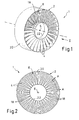
- An inventive air guide 1 consists of a one-piece molding 2 in particular made of plastic (injection molded part).
- the air guide element 1 has a plurality of air guide vanes 4, which are distributed in the circumferential direction about a longitudinal axis 6 around and are arranged substantially radially.
- the longitudinal axis 6 corresponds essentially to the desired flow direction of a medium flowing through the air guide element 1, in particular air, wherein the longitudinal axis 6 in Fig. 2 perpendicular to the plane of the drawing.
- the air guiding element 1 furthermore has a protective grille 8, which is integrally connected to the air guide vanes 4.
- the spoiler 1 is immediately downstream of an axial fan, not shown, and it also serves as protection against contact by the protective grid 8.
- the air guide vanes 4 each extend obliquely to the axial direction between an inflow-side blade edge 10 facing the fan and an opposite, outflow-side blade edge 12.
- the air guide vanes 4 can each have a wing-like design with a contour that is curved in the circumferential direction in such a way that they have a greater oblique inclination in the region of the inflow-side blade edges 10 than in the region of the downstream blade edges 12. This is in particular on Fig. 3 directed. It is clear that the air coming from the fan wheel on the inflow side in the direction of the arrow 14 is deflected over the air guide vanes 4 in the axial direction according to the arrows 16.
- the guard 8 is according to Fig. 1 and 2 from concentric and in particular annular in the circumferential direction, integrally connected to the air guide vanes 4 grid webs 18th
- the grid webs 18 consist of web sections 18a, wherein each web section 18a is connected at one end to the leading edge 10 of one of the air guide vanes 4 and the other downstream end edge 12 of the circumferentially adjacent air guide 4. According to 3 and 4 Thus, the web portions 18a and the air vanes 4 extend in the circumferential direction zigzag axially back and forth.
- the one-piece mold part 2 in a two-part mold only and can be removed from the mold due to a non-undercut design and slide-free.
- the air guide vanes 4 are connected in one piece with their radially outer ends with an outer ring 20 and with their inner ends with a coaxial inner ring 22.
- Both rings 20, 22 are preferably formed substantially hollow cylindrical.
- the grid webs 18 and their web portions 18a have been seen in axial plan view (see Fig. 2 ) An arcuate course, wherein the grid bars 18 extend a total of coaxial annular. It is also a spiral course possible.
- the outer ring 20 with the inner ring 22 integrally connecting spoiler blades 4 may be at least partially designed for a mechanical support function.
- radially not shown holding struts may be provided with mechanical support function between the outer ring 20 and the inner ring 22.
- the inner ring 22 In the region of the inner ring 22 means not shown are provided for connection to a fan or a drive motor, also not shown. Furthermore, 20 means for external attachment of the entire unit in a ventilation unit or a ventilation system are provided in the region of the outer ring (also not shown).
- the outer ring 20 encloses on the upstream side of the air guide vanes 4 a receiving space for a fan wheel. This means that the fan wheel to be arranged directly in front of the inflow-side blade edges 10 is still enclosed by the outer ring 20 at least in certain areas.
Landscapes
- Engineering & Computer Science (AREA)
- Mechanical Engineering (AREA)
- General Engineering & Computer Science (AREA)
- Physics & Mathematics (AREA)
- Geometry (AREA)
- Structures Of Non-Positive Displacement Pumps (AREA)
- Laying Of Electric Cables Or Lines Outside (AREA)
Abstract
Description
Die vorliegende Erfindung betrifft ein Luftleitelement für einen Axialventilator, bestehend aus einem einstückigen Formteil mit einer Mehrzahl von in Umfangsrichtung um eine Längsachse herum verteilt und im Wesentlichen radial angeordneten, flügelartigen Luftleitschaufeln sowie mit einem mit den Luftleitschaufeln integral verbundenen Schutzgitter, wobei die Luftleitschaufeln in Umfangsrichtung gesehen jeweils zwischen einer dem Ventilator zuzuwendenden anströmseitigen Schaufelkante und einer gegenüberliegenden abströmseitigen Schaufelkante schräg zur Achsrichtung geneigt verlaufen, und wobei das Schutzgitter aus konzentrischen und in Umfangsrichtung verlaufenden, mit den Luftleitschaufeln verbundenen Gitterstegen besteht.The present invention relates to an air guide element for an axial fan, consisting of a one-piece molded part with a plurality of circumferentially distributed around a longitudinal axis and substantially radially disposed wing-like air guide vanes and with an integrally connected to the air guide vanes, wherein the air guide vanes seen in the circumferential direction extend obliquely to the axial direction in each case between an inflow-side blade edge facing the fan and an opposite outflow-side blade edge, and wherein the protective grille consists of concentric and circumferentially extending grid webs connected to the air guide vanes.
Derartige Luftleitelemente werden mit ihren Luftleitschaufeln unmittelbar hinter einem Axialventilator angeordnet, um die von dem Axialventilator-Laufrad in Strömung versetzte Luft in eine möglichst axiale und gleichmäßige Strömung umzuleiten. Ein solches Luftleitelement wird deshalb häufig auch "Nachleitrad" oder "Strömungsgleichrichter" genannt.Such air guide elements are arranged with their air guide vanes immediately behind an axial fan to redirect the offset from the axial fan impeller air in a possible axial and uniform flow. Such an air guide is therefore often called "Nachleitrad" or "flow rectifier".
So beschreibt die
Der vorliegenden Erfindung liegt die Aufgabe zu Grunde, ein Luftleitelement der eingangs beschriebenen, gattungsgemäßen Art so zu verbessern, dass es mit strömungsgünstigen Eigenschaften auf besonders einfache und wirtschaftliche Weise herstellbar ist.The present invention is based on the object to improve an air guide element of the generic type described above so that it can be produced with streamlined properties in a particularly simple and economical manner.
Erfindungsgemäß wird dies durch die Merkmale des Anspruchs 1 erreicht. Vorteilhafte Ausgestaltungsmerkmale der Erfindung sind in den abhängigen Ansprüchen und der folgenden Beschreibung enthalten.This is achieved by the features of
Demnach ist erfindungsgemäß vorgesehen, dass die Gitterstege des Schutzgitters aus Stegabschnitten bestehen, die jeweils einendig mit den anströmseitigen (vorderen) Schaufelkanten der Luftleitschaufeln und anderendig mit den jeweils nächstliegenden abströmseitigen (hinteren) Schaufelkanten der jeweils in Umfangsrichtung benachbarten Luftleitschaufeln verbunden sind. Daraus resultiert praktisch ein in Umfangsrichtung gesehen zickzackförmiger Verlauf der Stegabschnitte des Schutzgitters und der Luftleitschaufeln, und zwar derart, dass das Formteil in einem einfachen Formwerkzeug mit zwei schieberfreien Formhälften einteilig formbar und entformbar ist, und zwar aufgrund einer in Entformrichtung der Formhälften hinterschnittfreien Ausgestaltung.Accordingly, the invention provides that the grid webs of the protective grid consist of web sections, which are each connected at one end to the upstream (front) blade edges of the air vanes and the other end with the respective downstream downstream (rear) blade edges of each adjacent circumferentially air vanes. This results in a practically zigzag course in the circumferential direction of the web sections of the protective grille and the air guide vanes, in such a way that the molding is integrally moldable and demoldable in a simple mold with two slider-free mold halves, due to an undercut-free design in Entformrichtung the mold halves.
Der besondere, erfindungsgemäße Verlauf der Gitterstege bzw. der Stegabschnitte des Schutzgitters beeinträchtigt vorteilhafterweise nicht die strömungsgünstigen Eigenschaften des Luftleitelementes. Indem die Luftleitschaufeln jeweils eine flügelartige Ausbildung mit einem derart in Umfangsrichtung gekrümmten Konturverlauf aufweisen, dass sie im Bereich der anströmseitigen Schaufelkanten eine größere Schrägneigung als im Bereich der abströmseitigen Schaufelkanten haben, wird eine günstige Strömungsführung und Strömungslenkung erreicht. Durch die Luftleitschaufeln wird die Umfangskomponente der Abströmgeschwindigkeit der Ventilatorströmung in Achsrichtung nahezu verlustfrei umgelenkt, so dass Geschwindigkeitsenergie in statischen Druck rückgewandelt wird.The particular, inventive course of the grid webs or the web portions of the protective grid advantageously does not affect the streamlined properties of the air guide element. Since the air guide vanes each have a wing-like design with a contour that is curved in the circumferential direction in such a way that they have a greater oblique inclination in the region of the upstream blade edges than in the region of the downstream blade edges, a favorable flow guidance and flow guidance is achieved. By the air guide vanes, the peripheral component of the outflow velocity of Fan flow in the axial direction deflected almost lossless, so that speed energy is converted back into static pressure.
In vorteilhafter Ausgestaltung sind die Luftleitschaufeln mit ihren radial äußeren Enden mit einem im Wesentlichen hohlzylindrischen Außenring und mit ihren inneren Enden mit einem koaxialen, insbesondere ebenfalls im Wesentlichen hohlzylindrischen Innenring einstückig verbunden. Über den Innenring kann das Luftleitelement mit einer Ventilatoreinheit bzw. mit einem Antriebsmotor verbunden werden. Die Ventilatoreinheit weist ein Axial-Ventilatorrad auf, welches unmittelbar vor der Anströmseite der Luftleitschaufeln anzuordnen ist. Hierbei bildet der Außenring auch einen Aufnahmeraum für das Ventilatorrad. Der Außenring dient zur äußeren Befestigung der gesamten Einheit in einem Lüftungsgerät oder einer Lüftungsanlage. Hierbei können die den Außenring mit dem Innenring einstückig verbindenden Luftleitschaufeln auch zumindest anteilig mit einer mechanischenTragfunktion ausgelegt sein, um Kräfte und Drehmomente des Ventilatormotors auf den Außenring zu übertragen. Es können aber auch zusätzliche, radial zwischen dem Außenring und dem Innenring angeordnete Haltestreben mit mechanischer Tragfunktion vorgesehen sein.In an advantageous embodiment, the air vanes are connected in one piece with their radially outer ends with a substantially hollow cylindrical outer ring and with their inner ends with a coaxial, in particular also substantially hollow cylindrical inner ring. About the inner ring, the air guide can be connected to a fan unit or with a drive motor. The fan unit has an axial fan wheel, which is to be arranged immediately in front of the inflow side of the air guide vanes. Here, the outer ring also forms a receiving space for the fan wheel. The outer ring is used for external attachment of the entire unit in a ventilation unit or a ventilation system. In this case, the air guide vanes integrally connecting the outer ring to the inner ring can also be designed at least proportionally with a mechanical bearing function in order to transmit forces and torques of the fan motor to the outer ring. But it can also be provided with a mechanical support function additional, arranged radially between the outer ring and the inner ring holding struts.
Anhand eines in der Zeichnung veranschaulichten, bevorzugten Ausführungsbeispiels soll die Erfindung genauer erläutert werden. Dabei zeigen:
- Fig. 1
- eine Perspektivansicht eines erfindungsgemäßen Luftleitelementes,
- Fig. 2
- eine axiale Draufsicht in Pfeilrichtung II gemäß
Fig. 1 , - Fig. 3
- eine vergrößerte Abwicklung bzw. einen umfänglichen Schnitt eines Teilbereiches des Luftleitelementes entsprechend der Linie A-A in
Fig. 2 und - Fig. 4
- einen Ausschnitt eines Teilbereiches der Luftleitschaufeln in Perspektivansicht zur Erläuterung der besonderen Ausgestaltung des Schutzgitters.
- Fig. 1
- a perspective view of an air guide element according to the invention,
- Fig. 2
- an axial plan view in the direction of arrow II according to
Fig. 1 . - Fig. 3
- an enlarged development or a circumferential section of a portion of the air guide element according to the line AA in
Fig. 2 and - Fig. 4
- a section of a portion of the air guide vanes in perspective view to explain the particular embodiment of the protective grid.
In den verschiedenen Figuren der Zeichnung sind gleiche Teile stets mit den gleichen Bezugszeichen versehen.In the various figures of the drawing, like parts are always provided with the same reference numerals.
Ein erfindungsgemäßes Luftleitelement 1 besteht aus einem einstückigen Formteil 2 insbesondere aus Kunststoff (Spritzgussteil). Das Luftleitelement 1 weist eine Mehrzahl von Luftleitschaufeln 4 auf, die in Umfangsrichtung um eine Längsachse 6 herum verteilt und im Wesentlichen radial angeordnet sind. Die Längsachse 6 entspricht im Wesentlichen der gewünschten Strömungsrichtung eines das Luftleitelement 1 durchströmenden Mediums, insbesondere Luft, wobei die Längsachse 6 in
Die Luftleitschaufeln 4 verlaufen in Umfangsrichtung gesehen jeweils zwischen einer dem Ventilator zuzuwendenden anströmseitigen Schaufelkante 10 und einer gegenüberliegenden, abströmseitigen Schaufelkante 12 schräg zur Achsrichtung geneigt. Hierbei können die Luftleitschaufeln 4 jeweils eine flügelartige Ausbildung mit einem in Umfangsrichtung derart gekrümmten Konturverlauf aufweisen, dass sie im Bereich der anströmseitigen Schaufelkanten 10 eine größere Schrägneigung als im Bereich der abströmseitigen Schaufelkanten 12 haben. Hierzu wird insbesondere auf
Das Schutzgitter 8 besteht gemäß
Wie sich nun insbesondere aus
Anhand der Darstellungen in
Gemäß
In bevorzugter Ausgestaltung haben die Gitterstege 18 bzw. deren Stegabschnitte 18a in axialer Draufsicht gesehen (siehe
Die den Außenring 20 mit dem Innenring 22 integral verbindenden Luftleitschaufeln 4 können zumindest anteilig für eine mechanische Tragfunktion ausgelegt sein. Zusätzlich können radial zwischen dem Außenring 20 und dem Innenring 22 nicht dargestellte Haltestreben mit mechanischer Tragfunktion vorgesehen sein.The
Im Bereich des Innenrings 22 sind nicht dargestellte Mittel zur Verbindung mit einem ebenfalls nicht dargestellten Ventilator bzw. einem Antriebsmotor vorgesehen. Weiterhin sind im Bereich des Außenrings 20 Mittel zur äußeren Befestigung der gesamten Einheit in einem Lüftungsgerät oder einer Lüftungsanlage vorgesehen (ebenfalls nicht dargestellt).In the region of the
Wie sich noch aus
Claims (9)
- Air guiding element (1) for an axial fan, consisting of a one-piece moulded part (2) with a plurality of air guide vanes (4) which are arranged in a manner distributed in the circumferential direction around a longitudinal axis (6) and substantially radially and with a protective grating (8) integrally connected to the air guide vanes (4), the air guide vanes (4), viewed in the circumferential direction, each running between an inflow-side vane edge (10) and an outflow-side vane edge (12) in a manner inclined obliquely with respect to the axial direction, and the protective grating (8) consisting of substantially concentric grating webs (18) running in the circumferential direction and connected to the air guide vanes (4),
characterised in that the grating webs (18) of the protective grating (8) consist of web sections (18a), which are each connected at one end to the inflow-side vane edges (10) of the air guide vanes (4) and at the other end to the outflow-side vane edges (12) of the respectively neighbouring air guide vanes (4) in the circumferential direction. - Air guiding element according to Claim 1,
characterised in that the air guide vanes (4) are connected in one piece by their radially outer ends to an outer ring (20) and by their inner ends to a coaxial inner ring (22). - Air guiding element according to Claim 1 or 2,
characterised in that the air guide vanes (4) each have a wing-like design with a contour course which is curved in such a way in the circumferential direction that they have a greater oblique inclination in the region of the inflow-side vane edges (10) than in the region of the outflow-side vane edges (12). - Air guiding element according to one of Claims 1 to 3,
characterised in that the grating webs (18) as a whole run coaxially annularly. - Air guiding element according to Claim 2 and one of Claims 3 to 4,
characterised in that the moulded part (2) has additional holding struts with a mechanical supporting function which are arranged radially between the outer ring (20) and the inner ring (22). - Air guiding element according to Claim 2 and one of Claims 3 to 5,
characterised in that the air guide vanes (4), which connect the outer ring (20) to the inner ring (22), are also designed at least partially for a mechanical supporting function. - Air guiding element according to Claim 2 and one of Claims 3 to 6,
characterised in that means for mounting a fan are provided in the region of the inner ring (22). - Air guiding element according to Claim 2 and one of Claims 3 to 7,
characterised in that means for external fastening are provided in the region of the outer ring (20). - Air guiding element according to Claim 2 and one of Claims 3 to 8,
characterised in that the outer ring (20) encloses a receiving space for a fan wheel on the inflow side of the air guide vanes (4).
Applications Claiming Priority (1)
| Application Number | Priority Date | Filing Date | Title |
|---|---|---|---|
| DE202009014212U DE202009014212U1 (en) | 2009-10-21 | 2009-10-21 | Air guide element for an axial fan |
Publications (2)
| Publication Number | Publication Date |
|---|---|
| EP2314882A1 EP2314882A1 (en) | 2011-04-27 |
| EP2314882B1 true EP2314882B1 (en) | 2012-03-14 |
Family
ID=43478767
Family Applications (1)
| Application Number | Title | Priority Date | Filing Date |
|---|---|---|---|
| EP10187222A Active EP2314882B1 (en) | 2009-10-21 | 2010-10-12 | Air guiding element for an axial ventilator |
Country Status (6)
| Country | Link |
|---|---|
| EP (1) | EP2314882B1 (en) |
| AT (1) | ATE549518T1 (en) |
| DE (1) | DE202009014212U1 (en) |
| DK (1) | DK2314882T3 (en) |
| ES (1) | ES2382425T3 (en) |
| PT (1) | PT2314882E (en) |
Families Citing this family (4)
| Publication number | Priority date | Publication date | Assignee | Title |
|---|---|---|---|---|
| DE102016007205A1 (en) | 2016-06-08 | 2017-12-14 | Ziehl-Abegg Se | fan unit |
| WO2019115703A1 (en) | 2017-12-13 | 2019-06-20 | Ebm-Papst Mulfingen Gmbh & Co. Kg | Diagonal fan wheel with increased strength |
| DE102018128792A1 (en) | 2018-11-16 | 2020-05-20 | Ebm-Papst Mulfingen Gmbh & Co. Kg | Compact diagonal fan with guide device |
| DE102018128791A1 (en) * | 2018-11-16 | 2020-05-20 | Ebm-Papst Mulfingen Gmbh & Co. Kg | Diagonal fan with guide device |
Family Cites Families (6)
| Publication number | Priority date | Publication date | Assignee | Title |
|---|---|---|---|---|
| DE2345539A1 (en) * | 1973-09-10 | 1975-03-20 | Siemens Ag | Wire inlet guard for wall mounted fan - has radial supports at angle to direction of flow |
| ES2550999T3 (en) * | 1999-08-09 | 2015-11-13 | Daikin Industries, Ltd. | Fan guard of a blower and air conditioning unit |
| DE10162919A1 (en) * | 2001-12-20 | 2003-07-03 | Bsh Bosch Siemens Hausgeraete | fan device |
| JP2004156884A (en) * | 2002-11-08 | 2004-06-03 | Daikin Ind Ltd | Fan guard for blower unit |
| US7118333B2 (en) * | 2002-11-22 | 2006-10-10 | Nidec Corporation | Electric cooling fan and case of electronic or electric device |
| EP1895166B1 (en) | 2006-08-30 | 2009-02-11 | Ralf Meier | Flow director for a fan |
-
2009
- 2009-10-21 DE DE202009014212U patent/DE202009014212U1/en not_active Expired - Lifetime
-
2010
- 2010-10-12 ES ES10187222T patent/ES2382425T3/en active Active
- 2010-10-12 AT AT10187222T patent/ATE549518T1/en active
- 2010-10-12 EP EP10187222A patent/EP2314882B1/en active Active
- 2010-10-12 PT PT10187222T patent/PT2314882E/en unknown
- 2010-10-12 DK DK10187222.4T patent/DK2314882T3/en active
Also Published As
| Publication number | Publication date |
|---|---|
| PT2314882E (en) | 2012-03-28 |
| DE202009014212U1 (en) | 2011-03-03 |
| ATE549518T1 (en) | 2012-03-15 |
| DK2314882T3 (en) | 2012-07-09 |
| EP2314882A1 (en) | 2011-04-27 |
| ES2382425T3 (en) | 2012-06-08 |
Similar Documents
| Publication | Publication Date | Title |
|---|---|---|
| DE19929978B4 (en) | Fan with axial blades | |
| EP2737189B1 (en) | Cooling fan module | |
| EP2418389B1 (en) | Impeller for a ventilator | |
| EP2549116B1 (en) | Axial ventilator with additional flow channel | |
| DE3412916C2 (en) | Fan blades | |
| EP1774180B1 (en) | Radial fan wheel | |
| EP2236837B1 (en) | Axial ventilator, in particular for a motor vehicle | |
| EP1276994B1 (en) | Blower especially for ventilating electronic devices | |
| EP3824190B1 (en) | Ventilator and deflector plate for a ventilator | |
| EP2771581B1 (en) | Axial ventilator wheel | |
| DE69817526T2 (en) | AXIAL FAN | |
| DE19615237A1 (en) | Exhaust gas turbocharger for an internal combustion engine | |
| DE102018115000A1 (en) | FAN SYSTEM WITH INTEGRATED FAN COIL CHANNEL FOR REDUCED FLOW RATE | |
| EP2314882B1 (en) | Air guiding element for an axial ventilator | |
| EP2886873B1 (en) | Axial ventilator | |
| EP2994615B1 (en) | Rotor for a thermal turbomachine | |
| EP1081336B1 (en) | Vane ring assembly for gas turbines | |
| WO2011012352A1 (en) | Entering geometry for half-axial fan wheels | |
| EP1914402B1 (en) | Axial fan and method for preventing a recirculation flow | |
| EP3617529B1 (en) | Fan frame of a motor vehicle | |
| EP1887195B1 (en) | Cooling device for a motor vehicle | |
| WO2021143972A1 (en) | Housing for a fan, and fan with a corresponding housing | |
| EP2329149B1 (en) | Diagonal fan | |
| EP3114354B1 (en) | Fan wheel of an axial fan | |
| EP2225467B1 (en) | Swirl-generating apparatus and turbocharger with such a swirl-generating apparatus |
Legal Events
| Date | Code | Title | Description |
|---|---|---|---|
| PUAI | Public reference made under article 153(3) epc to a published international application that has entered the european phase |
Free format text: ORIGINAL CODE: 0009012 |
|
| 17P | Request for examination filed |
Effective date: 20110226 |
|
| AK | Designated contracting states |
Kind code of ref document: A1 Designated state(s): AL AT BE BG CH CY CZ DE DK EE ES FI FR GB GR HR HU IE IS IT LI LT LU LV MC MK MT NL NO PL PT RO RS SE SI SK SM TR |
|
| AX | Request for extension of the european patent |
Extension state: BA ME |
|
| GRAP | Despatch of communication of intention to grant a patent |
Free format text: ORIGINAL CODE: EPIDOSNIGR1 |
|
| RIC1 | Information provided on ipc code assigned before grant |
Ipc: F04D 29/54 20060101ALI20110912BHEP Ipc: F04D 29/70 20060101ALI20110912BHEP Ipc: F04D 29/52 20060101AFI20110912BHEP |
|
| GRAS | Grant fee paid |
Free format text: ORIGINAL CODE: EPIDOSNIGR3 |
|
| GRAA | (expected) grant |
Free format text: ORIGINAL CODE: 0009210 |
|
| AK | Designated contracting states |
Kind code of ref document: B1 Designated state(s): AL AT BE BG CH CY CZ DE DK EE ES FI FR GB GR HR HU IE IS IT LI LT LU LV MC MK MT NL NO PL PT RO RS SE SI SK SM TR |
|
| REG | Reference to a national code |
Ref country code: GB Ref legal event code: FG4D Free format text: NOT ENGLISH |
|
| REG | Reference to a national code |
Ref country code: AT Ref legal event code: REF Ref document number: 549518 Country of ref document: AT Kind code of ref document: T Effective date: 20120315 Ref country code: CH Ref legal event code: EP |
|
| REG | Reference to a national code |
Ref country code: PT Ref legal event code: SC4A Free format text: AVAILABILITY OF NATIONAL TRANSLATION Effective date: 20120315 |
|
| REG | Reference to a national code |
Ref country code: IE Ref legal event code: FG4D Free format text: LANGUAGE OF EP DOCUMENT: GERMAN |
|
| REG | Reference to a national code |
Ref country code: NL Ref legal event code: T3 |
|
| REG | Reference to a national code |
Ref country code: DE Ref legal event code: R096 Ref document number: 502010000512 Country of ref document: DE Effective date: 20120510 |
|
| REG | Reference to a national code |
Ref country code: ES Ref legal event code: FG2A Ref document number: 2382425 Country of ref document: ES Kind code of ref document: T3 Effective date: 20120608 |
|
| REG | Reference to a national code |
Ref country code: SE Ref legal event code: TRGR |
|
| REG | Reference to a national code |
Ref country code: DK Ref legal event code: T3 |
|
| REG | Reference to a national code |
Ref country code: SE Ref legal event code: RPOT |
|
| PG25 | Lapsed in a contracting state [announced via postgrant information from national office to epo] |
Ref country code: HR Free format text: LAPSE BECAUSE OF FAILURE TO SUBMIT A TRANSLATION OF THE DESCRIPTION OR TO PAY THE FEE WITHIN THE PRESCRIBED TIME-LIMIT Effective date: 20120314 Ref country code: LT Free format text: LAPSE BECAUSE OF FAILURE TO SUBMIT A TRANSLATION OF THE DESCRIPTION OR TO PAY THE FEE WITHIN THE PRESCRIBED TIME-LIMIT Effective date: 20120314 |
|
| REG | Reference to a national code |
Ref country code: NO Ref legal event code: T2 Effective date: 20120314 |
|
| LTIE | Lt: invalidation of european patent or patent extension |
Effective date: 20120314 |
|
| PG25 | Lapsed in a contracting state [announced via postgrant information from national office to epo] |
Ref country code: RS Free format text: LAPSE BECAUSE OF FAILURE TO SUBMIT A TRANSLATION OF THE DESCRIPTION OR TO PAY THE FEE WITHIN THE PRESCRIBED TIME-LIMIT Effective date: 20120314 Ref country code: LV Free format text: LAPSE BECAUSE OF FAILURE TO SUBMIT A TRANSLATION OF THE DESCRIPTION OR TO PAY THE FEE WITHIN THE PRESCRIBED TIME-LIMIT Effective date: 20120314 Ref country code: GR Free format text: LAPSE BECAUSE OF FAILURE TO SUBMIT A TRANSLATION OF THE DESCRIPTION OR TO PAY THE FEE WITHIN THE PRESCRIBED TIME-LIMIT Effective date: 20120615 |
|
| PG25 | Lapsed in a contracting state [announced via postgrant information from national office to epo] |
Ref country code: CY Free format text: LAPSE BECAUSE OF FAILURE TO SUBMIT A TRANSLATION OF THE DESCRIPTION OR TO PAY THE FEE WITHIN THE PRESCRIBED TIME-LIMIT Effective date: 20120314 |
|
| PG25 | Lapsed in a contracting state [announced via postgrant information from national office to epo] |
Ref country code: CZ Free format text: LAPSE BECAUSE OF FAILURE TO SUBMIT A TRANSLATION OF THE DESCRIPTION OR TO PAY THE FEE WITHIN THE PRESCRIBED TIME-LIMIT Effective date: 20120314 Ref country code: SI Free format text: LAPSE BECAUSE OF FAILURE TO SUBMIT A TRANSLATION OF THE DESCRIPTION OR TO PAY THE FEE WITHIN THE PRESCRIBED TIME-LIMIT Effective date: 20120314 Ref country code: EE Free format text: LAPSE BECAUSE OF FAILURE TO SUBMIT A TRANSLATION OF THE DESCRIPTION OR TO PAY THE FEE WITHIN THE PRESCRIBED TIME-LIMIT Effective date: 20120314 Ref country code: RO Free format text: LAPSE BECAUSE OF FAILURE TO SUBMIT A TRANSLATION OF THE DESCRIPTION OR TO PAY THE FEE WITHIN THE PRESCRIBED TIME-LIMIT Effective date: 20120314 Ref country code: IS Free format text: LAPSE BECAUSE OF FAILURE TO SUBMIT A TRANSLATION OF THE DESCRIPTION OR TO PAY THE FEE WITHIN THE PRESCRIBED TIME-LIMIT Effective date: 20120714 Ref country code: PL Free format text: LAPSE BECAUSE OF FAILURE TO SUBMIT A TRANSLATION OF THE DESCRIPTION OR TO PAY THE FEE WITHIN THE PRESCRIBED TIME-LIMIT Effective date: 20120314 |
|
| PG25 | Lapsed in a contracting state [announced via postgrant information from national office to epo] |
Ref country code: SK Free format text: LAPSE BECAUSE OF FAILURE TO SUBMIT A TRANSLATION OF THE DESCRIPTION OR TO PAY THE FEE WITHIN THE PRESCRIBED TIME-LIMIT Effective date: 20120314 |
|
| PLBE | No opposition filed within time limit |
Free format text: ORIGINAL CODE: 0009261 |
|
| STAA | Information on the status of an ep patent application or granted ep patent |
Free format text: STATUS: NO OPPOSITION FILED WITHIN TIME LIMIT |
|
| 26N | No opposition filed |
Effective date: 20121217 |
|
| REG | Reference to a national code |
Ref country code: DE Ref legal event code: R097 Ref document number: 502010000512 Country of ref document: DE Effective date: 20121217 |
|
| PG25 | Lapsed in a contracting state [announced via postgrant information from national office to epo] |
Ref country code: MC Free format text: LAPSE BECAUSE OF NON-PAYMENT OF DUE FEES Effective date: 20121031 |
|
| REG | Reference to a national code |
Ref country code: IE Ref legal event code: MM4A |
|
| PG25 | Lapsed in a contracting state [announced via postgrant information from national office to epo] |
Ref country code: IE Free format text: LAPSE BECAUSE OF NON-PAYMENT OF DUE FEES Effective date: 20121012 Ref country code: BG Free format text: LAPSE BECAUSE OF FAILURE TO SUBMIT A TRANSLATION OF THE DESCRIPTION OR TO PAY THE FEE WITHIN THE PRESCRIBED TIME-LIMIT Effective date: 20120614 |
|
| PG25 | Lapsed in a contracting state [announced via postgrant information from national office to epo] |
Ref country code: MT Free format text: LAPSE BECAUSE OF FAILURE TO SUBMIT A TRANSLATION OF THE DESCRIPTION OR TO PAY THE FEE WITHIN THE PRESCRIBED TIME-LIMIT Effective date: 20120314 Ref country code: AL Free format text: LAPSE BECAUSE OF FAILURE TO SUBMIT A TRANSLATION OF THE DESCRIPTION OR TO PAY THE FEE WITHIN THE PRESCRIBED TIME-LIMIT Effective date: 20120314 |
|
| PG25 | Lapsed in a contracting state [announced via postgrant information from national office to epo] |
Ref country code: LU Free format text: LAPSE BECAUSE OF NON-PAYMENT OF DUE FEES Effective date: 20121012 Ref country code: SM Free format text: LAPSE BECAUSE OF FAILURE TO SUBMIT A TRANSLATION OF THE DESCRIPTION OR TO PAY THE FEE WITHIN THE PRESCRIBED TIME-LIMIT Effective date: 20120314 |
|
| PG25 | Lapsed in a contracting state [announced via postgrant information from national office to epo] |
Ref country code: HU Free format text: LAPSE BECAUSE OF FAILURE TO SUBMIT A TRANSLATION OF THE DESCRIPTION OR TO PAY THE FEE WITHIN THE PRESCRIBED TIME-LIMIT Effective date: 20101012 |
|
| REG | Reference to a national code |
Ref country code: CH Ref legal event code: PL |
|
| PG25 | Lapsed in a contracting state [announced via postgrant information from national office to epo] |
Ref country code: MK Free format text: LAPSE BECAUSE OF FAILURE TO SUBMIT A TRANSLATION OF THE DESCRIPTION OR TO PAY THE FEE WITHIN THE PRESCRIBED TIME-LIMIT Effective date: 20120314 Ref country code: CH Free format text: LAPSE BECAUSE OF NON-PAYMENT OF DUE FEES Effective date: 20141031 Ref country code: LI Free format text: LAPSE BECAUSE OF NON-PAYMENT OF DUE FEES Effective date: 20141031 |
|
| REG | Reference to a national code |
Ref country code: FR Ref legal event code: PLFP Year of fee payment: 6 |
|
| REG | Reference to a national code |
Ref country code: FR Ref legal event code: PLFP Year of fee payment: 7 |
|
| REG | Reference to a national code |
Ref country code: FR Ref legal event code: PLFP Year of fee payment: 8 |
|
| REG | Reference to a national code |
Ref country code: DE Ref legal event code: R082 Ref document number: 502010000512 Country of ref document: DE Representative=s name: PATENTANWAELTE STAEGER & SPERLING PARTNERSCHAF, DE |
|
| REG | Reference to a national code |
Ref country code: FR Ref legal event code: PLFP Year of fee payment: 9 |
|
| PGFP | Annual fee paid to national office [announced via postgrant information from national office to epo] |
Ref country code: PT Payment date: 20230929 Year of fee payment: 14 Ref country code: NL Payment date: 20231023 Year of fee payment: 14 |
|
| PGFP | Annual fee paid to national office [announced via postgrant information from national office to epo] |
Ref country code: GB Payment date: 20231025 Year of fee payment: 14 |
|
| PGFP | Annual fee paid to national office [announced via postgrant information from national office to epo] |
Ref country code: ES Payment date: 20231117 Year of fee payment: 14 |
|
| PGFP | Annual fee paid to national office [announced via postgrant information from national office to epo] |
Ref country code: TR Payment date: 20231004 Year of fee payment: 14 Ref country code: SE Payment date: 20231025 Year of fee payment: 14 Ref country code: NO Payment date: 20231023 Year of fee payment: 14 Ref country code: IT Payment date: 20231031 Year of fee payment: 14 Ref country code: FR Payment date: 20231023 Year of fee payment: 14 Ref country code: FI Payment date: 20231023 Year of fee payment: 14 Ref country code: DK Payment date: 20231025 Year of fee payment: 14 Ref country code: DE Payment date: 20231018 Year of fee payment: 14 Ref country code: AT Payment date: 20231019 Year of fee payment: 14 |
|
| PGFP | Annual fee paid to national office [announced via postgrant information from national office to epo] |
Ref country code: BE Payment date: 20231023 Year of fee payment: 14 |