EP2314521A1 - Kartusche mit integrierter Verschlusskappe - Google Patents
Kartusche mit integrierter Verschlusskappe Download PDFInfo
- Publication number
- EP2314521A1 EP2314521A1 EP10177971A EP10177971A EP2314521A1 EP 2314521 A1 EP2314521 A1 EP 2314521A1 EP 10177971 A EP10177971 A EP 10177971A EP 10177971 A EP10177971 A EP 10177971A EP 2314521 A1 EP2314521 A1 EP 2314521A1
- Authority
- EP
- European Patent Office
- Prior art keywords
- cartridge
- neck
- closure cap
- outlet channel
- outlet
- Prior art date
- Legal status (The legal status is an assumption and is not a legal conclusion. Google has not performed a legal analysis and makes no representation as to the accuracy of the status listed.)
- Withdrawn
Links
- 238000010521 absorption reaction Methods 0.000 claims abstract description 12
- 238000003860 storage Methods 0.000 claims description 52
- 230000035939 shock Effects 0.000 claims description 29
- 150000001875 compounds Chemical class 0.000 claims description 23
- 230000000717 retained effect Effects 0.000 claims description 2
- 239000000463 material Substances 0.000 description 35
- 230000009969 flowable effect Effects 0.000 description 11
- 238000005192 partition Methods 0.000 description 6
- 238000007789 sealing Methods 0.000 description 6
- GLGNXYJARSMNGJ-VKTIVEEGSA-N (1s,2s,3r,4r)-3-[[5-chloro-2-[(1-ethyl-6-methoxy-2-oxo-4,5-dihydro-3h-1-benzazepin-7-yl)amino]pyrimidin-4-yl]amino]bicyclo[2.2.1]hept-5-ene-2-carboxamide Chemical compound CCN1C(=O)CCCC2=C(OC)C(NC=3N=C(C(=CN=3)Cl)N[C@H]3[C@H]([C@@]4([H])C[C@@]3(C=C4)[H])C(N)=O)=CC=C21 GLGNXYJARSMNGJ-VKTIVEEGSA-N 0.000 description 4
- 229940125758 compound 15 Drugs 0.000 description 4
- 230000008878 coupling Effects 0.000 description 4
- 238000010168 coupling process Methods 0.000 description 4
- 238000005859 coupling reaction Methods 0.000 description 4
- 239000000243 solution Substances 0.000 description 3
- 230000003068 static effect Effects 0.000 description 3
- 239000012780 transparent material Substances 0.000 description 3
- 230000007423 decrease Effects 0.000 description 2
- 238000007599 discharging Methods 0.000 description 2
- 230000000694 effects Effects 0.000 description 2
- 239000000945 filler Substances 0.000 description 2
- 239000012530 fluid Substances 0.000 description 2
- 238000001746 injection moulding Methods 0.000 description 2
- 230000003993 interaction Effects 0.000 description 2
- 238000009423 ventilation Methods 0.000 description 2
- 239000000853 adhesive Substances 0.000 description 1
- 230000001070 adhesive effect Effects 0.000 description 1
- 238000005452 bending Methods 0.000 description 1
- 238000006243 chemical reaction Methods 0.000 description 1
- 238000004891 communication Methods 0.000 description 1
- 230000010354 integration Effects 0.000 description 1
- 238000004519 manufacturing process Methods 0.000 description 1
- 239000012528 membrane Substances 0.000 description 1
- 238000000034 method Methods 0.000 description 1
- 239000000203 mixture Substances 0.000 description 1
- 238000003032 molecular docking Methods 0.000 description 1
- 229920003023 plastic Polymers 0.000 description 1
- 238000002360 preparation method Methods 0.000 description 1
- 230000000750 progressive effect Effects 0.000 description 1
- 239000012858 resilient material Substances 0.000 description 1
- 239000000565 sealant Substances 0.000 description 1
- 238000011144 upstream manufacturing Methods 0.000 description 1
- 238000013022 venting Methods 0.000 description 1
Images


Classifications
-
- B—PERFORMING OPERATIONS; TRANSPORTING
- B65—CONVEYING; PACKING; STORING; HANDLING THIN OR FILAMENTARY MATERIAL
- B65D—CONTAINERS FOR STORAGE OR TRANSPORT OF ARTICLES OR MATERIALS, e.g. BAGS, BARRELS, BOTTLES, BOXES, CANS, CARTONS, CRATES, DRUMS, JARS, TANKS, HOPPERS, FORWARDING CONTAINERS; ACCESSORIES, CLOSURES, OR FITTINGS THEREFOR; PACKAGING ELEMENTS; PACKAGES
- B65D81/00—Containers, packaging elements, or packages, for contents presenting particular transport or storage problems, or adapted to be used for non-packaging purposes after removal of contents
- B65D81/32—Containers, packaging elements, or packages, for contents presenting particular transport or storage problems, or adapted to be used for non-packaging purposes after removal of contents for packaging two or more different materials which must be maintained separate prior to use in admixture
- B65D81/325—Containers having parallel or coaxial compartments, provided with a piston or a movable bottom for discharging contents
-
- B—PERFORMING OPERATIONS; TRANSPORTING
- B05—SPRAYING OR ATOMISING IN GENERAL; APPLYING FLUENT MATERIALS TO SURFACES, IN GENERAL
- B05C—APPARATUS FOR APPLYING FLUENT MATERIALS TO SURFACES, IN GENERAL
- B05C17/00—Hand tools or apparatus using hand held tools, for applying liquids or other fluent materials to, for spreading applied liquids or other fluent materials on, or for partially removing applied liquids or other fluent materials from, surfaces
- B05C17/005—Hand tools or apparatus using hand held tools, for applying liquids or other fluent materials to, for spreading applied liquids or other fluent materials on, or for partially removing applied liquids or other fluent materials from, surfaces for discharging material from a reservoir or container located in or on the hand tool through an outlet orifice by pressure without using surface contacting members like pads or brushes
- B05C17/00503—Details of the outlet element
- B05C17/00506—Means for connecting the outlet element to, or for disconnecting it from, the hand tool or its container
- B05C17/00509—Means for connecting the outlet element to, or for disconnecting it from, the hand tool or its container of the bayonet type
-
- B—PERFORMING OPERATIONS; TRANSPORTING
- B05—SPRAYING OR ATOMISING IN GENERAL; APPLYING FLUENT MATERIALS TO SURFACES, IN GENERAL
- B05C—APPARATUS FOR APPLYING FLUENT MATERIALS TO SURFACES, IN GENERAL
- B05C17/00—Hand tools or apparatus using hand held tools, for applying liquids or other fluent materials to, for spreading applied liquids or other fluent materials on, or for partially removing applied liquids or other fluent materials from, surfaces
- B05C17/005—Hand tools or apparatus using hand held tools, for applying liquids or other fluent materials to, for spreading applied liquids or other fluent materials on, or for partially removing applied liquids or other fluent materials from, surfaces for discharging material from a reservoir or container located in or on the hand tool through an outlet orifice by pressure without using surface contacting members like pads or brushes
- B05C17/00503—Details of the outlet element
- B05C17/00506—Means for connecting the outlet element to, or for disconnecting it from, the hand tool or its container
- B05C17/00513—Means for connecting the outlet element to, or for disconnecting it from, the hand tool or its container of the thread type
-
- B—PERFORMING OPERATIONS; TRANSPORTING
- B05—SPRAYING OR ATOMISING IN GENERAL; APPLYING FLUENT MATERIALS TO SURFACES, IN GENERAL
- B05C—APPARATUS FOR APPLYING FLUENT MATERIALS TO SURFACES, IN GENERAL
- B05C17/00—Hand tools or apparatus using hand held tools, for applying liquids or other fluent materials to, for spreading applied liquids or other fluent materials on, or for partially removing applied liquids or other fluent materials from, surfaces
- B05C17/005—Hand tools or apparatus using hand held tools, for applying liquids or other fluent materials to, for spreading applied liquids or other fluent materials on, or for partially removing applied liquids or other fluent materials from, surfaces for discharging material from a reservoir or container located in or on the hand tool through an outlet orifice by pressure without using surface contacting members like pads or brushes
- B05C17/00553—Hand tools or apparatus using hand held tools, for applying liquids or other fluent materials to, for spreading applied liquids or other fluent materials on, or for partially removing applied liquids or other fluent materials from, surfaces for discharging material from a reservoir or container located in or on the hand tool through an outlet orifice by pressure without using surface contacting members like pads or brushes with means allowing the stock of material to consist of at least two different components
-
- B—PERFORMING OPERATIONS; TRANSPORTING
- B65—CONVEYING; PACKING; STORING; HANDLING THIN OR FILAMENTARY MATERIAL
- B65D—CONTAINERS FOR STORAGE OR TRANSPORT OF ARTICLES OR MATERIALS, e.g. BAGS, BARRELS, BOTTLES, BOXES, CANS, CARTONS, CRATES, DRUMS, JARS, TANKS, HOPPERS, FORWARDING CONTAINERS; ACCESSORIES, CLOSURES, OR FITTINGS THEREFOR; PACKAGING ELEMENTS; PACKAGES
- B65D47/00—Closures with filling and discharging, or with discharging, devices
- B65D47/04—Closures with discharging devices other than pumps
- B65D47/06—Closures with discharging devices other than pumps with pouring spouts or tubes; with discharge nozzles or passages
- B65D47/08—Closures with discharging devices other than pumps with pouring spouts or tubes; with discharge nozzles or passages having articulated or hinged closures
- B65D47/0804—Closures with discharging devices other than pumps with pouring spouts or tubes; with discharge nozzles or passages having articulated or hinged closures integrally formed with the base element provided with the spout or discharge passage
- B65D47/0828—Closures with discharging devices other than pumps with pouring spouts or tubes; with discharge nozzles or passages having articulated or hinged closures integrally formed with the base element provided with the spout or discharge passage and elastically biased towards the open position only
-
- B—PERFORMING OPERATIONS; TRANSPORTING
- B65—CONVEYING; PACKING; STORING; HANDLING THIN OR FILAMENTARY MATERIAL
- B65D—CONTAINERS FOR STORAGE OR TRANSPORT OF ARTICLES OR MATERIALS, e.g. BAGS, BARRELS, BOTTLES, BOXES, CANS, CARTONS, CRATES, DRUMS, JARS, TANKS, HOPPERS, FORWARDING CONTAINERS; ACCESSORIES, CLOSURES, OR FITTINGS THEREFOR; PACKAGING ELEMENTS; PACKAGES
- B65D83/00—Containers or packages with special means for dispensing contents
- B65D83/0005—Containers or packages provided with a piston or with a movable bottom or partition having approximately the same section as the container
Definitions
- the invention relates to a cartridge which is used in particular for processing a plurality of components.
- Such cartridges contain a filling material which is discharged for a specific application.
- the cartridge is particularly suitable for the simultaneous discharge of at least two components which can be mixed before use.
- a cartridge in its simplest embodiment is a tube with a neck.
- the tube serves as a storage chamber for the filling material.
- the tube ends at the discharge end in the neck.
- the neck contains an outlet channel, which opens into an outlet opening, through which the filling compound can continuously emerge as a jet or discontinuously in the form of drops.
- the user moves the piston in the direction of the neck.
- the filling material leaves the cartridge through the outlet channel of the neck and is applied at the location desired by the user.
- filler material There are several alternatives available for filling the cartridge with filler material.
- the piston is brought to a first alternative in a position which it occupies after completion of the conveying process, namely the position with a minimum distance to the outlet opening.
- the neck of the cartridge is immersed in a reservoir with filling material.
- the piston is moved away from the filling material from the outlet opening, so that filling material is introduced from the reservoir into the storage chamber.
- the storage chamber is successively filled with filling material until the piston has reached its end position at the end of delivery.
- the piston is removed from the storage chamber and the neck of the cartridge is either immediately closed when the filling material is thin or can remain temporarily open for the exit of air in the storage chamber.
- the filling compound is introduced from the conveyor end into the storage chamber.
- the filling can be done by means of a filling device.
- the filling device in its simplest form, is a hose connected to a reservoir, which is docked to the delivery end of the cartridge.
- a pump device connected to the hose, the storage chamber of the cartridge is filled with filling compound.
- the piston is again inserted into the storage chamber, so that the filling material is enclosed in the storage chamber between the piston and the still closed outlet opening.
- the cartridge is now ready for use and when it is ready to be stored and transported.
- the outlet opening may already be closed, for example with a closure cap which is screwed onto the neck containing the outlet opening, as for example in US Pat EP0578897 is shown.
- a cap may be provided that is integral with the cartridge neck, such as in the US Pat EP1491460 A2 is shown. This cap is connected via a predetermined breaking point with the outlet opening such that the outlet opening remains closed until the predetermined breaking point is severed by tearing the cap.
- the cap provided for this purpose should be in one piece and remain securely connected to the cartridge in the opened state.
- the object of the invention is achieved with a cartridge comprising a storage chamber for receiving a filling compound and a neck, which contains an outlet channel for the filling compound, so that the filling material can be discharged from the storage chamber through the outlet channel.
- the neck includes an end of the outlet channel, wherein an outlet opening is arranged at the end of the outlet channel, wherein the outlet opening can be closed by a closure cap.
- the cap is integrally connected to the cartridge. The outlet opening can be closed several times by the closure cap engaging in the end of the outlet channel in such a way that the filling compound is retained in the outlet channel.
- the cap remains connected via a connecting element with the cartridge when the outlet opening is free, thus the cap is open, that is, from the outlet end, which contains the outlet opening, is removed.
- the cartridge comprises a storage chamber for receiving a filling material, wherein the storage chamber has a volume which is variable and a cartridge neck, which contains an outlet channel for the filling material, so that the filling material can be discharged from the storage chamber through the cartridge neck.
- the cartridge neck is surrounded by a shock absorbing element formed integrally with the cartridge neck.
- the shock absorption element is designed such that the second end overhanging the neck. This ensures that the second of the neck remains intact in an impact, since the impact forces can be reduced by the deformation of at least the second end.
- a gap is formed, in which a housing element is receivable.
- a mixer can be connected or connected, especially if the cartridge is designed as a multi-component cartridge.
- the or each of the exit channels open into the mixer.
- the mixer is housed in an associated housing element which is slipped over the neck or inserted into the neck. This housing element should be referred to as a mixer housing.
- the mixer housing may be connected to the neck via a thread.
- the outlet channel is provided with an external thread on which the housing element can be screwed.
- the connection can also be done via a bayonet connection, a snap-in connection or via a snap connection, which is not shown in the drawing.
- the mixer can be designed in particular as a static mixer.
- a static mixer comprises a plurality of flow-redirecting internals, which are arranged in the mixer housing. The use of a mixer is particularly advantageous when the cartridge is used for a filling material, which consists of several flowable components.
- the jacket is arranged concentrically around the neck.
- the neck is a rotationally symmetrical component.
- the jacket can also be designed as a rotationally symmetrical component.
- the common axis of neck and mantle is the longitudinal axis of the neck.
- the mixer housing has a maximum diameter dimension that is smaller than the inner diameter of the shell so that it is rotatable within the shell.
- the mixer housing with the jacket for example, a plug connection, a snap-in connection, a snap connection or bayonet connection.
- coding means may be provided, as they are for example in the EP7390913 are shown to put the mixer housing in a well-defined position relative to the cartridge.
- the jacket of the shock absorption element advantageously has a substantially cylindrical inner wall.
- This cylindrical inner wall is easy to manufacture with the corresponding injection molding tool and allows the removal of the tool, by means of which the neck is made.
- the jacket contains an opening, so that the tool can be removed after completion of the neck through the opening.
- the shock absorbing element and the closure cap are formed integrally with the neck according to a preferred embodiment, that is, the shock absorbing element and the closure cap is made together with the neck and the entire cartridge as a single component.
- the first component according to the prior art comprises the cartridge with the neck.
- the second component comprises the cap located on the cartridge, which may optionally include a small cross-section outlet to facilitate the user dispensing small doses or portions of the desired component.
- the shock absorbing element projects beyond the cap in the closed state.
- the closure cap is advantageously connected to the cartridge, in particular the shock absorption element by means of a connecting element, which is advantageously designed as a hinge element.
- a connecting element has the advantage that the outlet opening can be closed again as often as desired. This means that the user has the option of discharging part of the filling material in the cartridge, of closing the closure cap and thus of storing a further part of the filling compound in the cartridge for later use.
- the closure cap may have an edge which rests on the neck when the closure cap is closed.
- the edge may have an outer diameter which is greater than the outer diameter of the neck.
- the edge may be formed as a projection, which may extend in particular at least over part of the circumference of the closure cap. The projection may at least partially enclose the neck.
- the edge may have an outer diameter which is greater than the outer diameter of the neck.
- At the edge of a fastener may be arranged, which can receive a tab of the cap to hold the cap in the closed state.
- the connecting element is preferably designed so that it remains in the unloaded state in the open position. After the closure cap has been moved to the closed state, the tab engages the connection element in order to hold the closure cap in the closed state.
- the closure cap has a receiving element into which the end of the outlet channel engages when the outlet opening is closed.
- the closure cap can have at least one annular groove into which the end of the neck, which forms the end of the outlet channel, is accommodated when the closure cap is closed. The end of the neck is received in the corresponding groove. If several outlet channels are provided, the neck can accordingly have a plurality of ends.
- a small pressure force can be exerted on the end of the neck by the closure cap in the closed state, so that a seal against the discharge of filling material is given.
- the walls of the groove can also be formed a labyrinth, which forms a filter section. This filter section has such a small opening width that the filling material can not get into the gap between the groove and the end of the neck.
- the end of the outlet channel may have a curvature directed in the direction of the longitudinal axis of the outlet channel.
- the wall thickness at the end of the outlet channel may be less than the wall thickness upstream of the end.
- the groove may have a conical cross-section, so that in the closed state, a sealing connection between the end of the neck, which forms that of the outlet channel, and the closure cap is made.
- the end of the neck is clamped between the two conical side walls of the groove so that the filling compound can not pass the nips at which the end of the outlet channel contact the side wall of the groove of the closure cap.
- the storage chamber may have a volume which is changeable. When the filling material is discharged, the volume of the storage chamber is reduced by a pressure applied to the wall of the storage chamber compressive force, since the wall consists of a resilient material.
- the storage chamber may be formed as a tube or as a tubular bag.
- the volume of the storage chamber may be changed by reciprocating a piston along the inner wall of the storage chamber.
- the cartridge according to one of the preceding embodiments comprises at least a first and a second sub-chamber.
- the first sub-chamber can accommodate a first component and the second sub-chamber a second component.
- the first sub-chamber opens into a first outlet channel and the second sub-chamber opens into a second outlet channel, wherein the first outlet channel has a first outlet opening and the second outlet channel has a second outlet opening.
- each of the components can be stored separately in the cartridge, but if necessary only the cap must be opened, a mixer is placed on each of the outlet openings and the two components can not only be discharged simultaneously but at the same time be mixed.
- the first outlet channel and the second outlet channel may be arranged in the neck.
- the first outlet channel opens into a first outlet opening, which is arranged in a first end of the neck.
- the second outlet channel opens into a second outlet opening, which is arranged in a second end of the neck.
- the first end of the neck may extend within the second end of the neck such that the second end is annularly disposed about the first end. In particular, the first end may be concentrically disposed within the second end.
- the second end may be located adjacent the first end.
- the first end and the second end are separated by a partition wall.
- the second end is received in the neck such that the neck has a rotationally symmetrical, that is to say in particular cylindrical or conical outer side.
- This has the advantage that the neck can have on its outside a fastener for the mixer.
- the already described external thread can be provided.
- the first outlet opening is arranged coaxially to the second outlet opening and the first outlet channel is arranged within the second outlet channel, wherein the first outlet channel is separated from the second outlet channel by an intermediate wall.
- the partition is in this case concentric with the mantle of the neck. The first component thus flows inside the intermediate wall, which limits the first outlet channel.
- the second component flows outside the intermediate wall through the second outlet channel, which is arranged in a ring around the first outlet channel.
- the first outlet channel can be arranged next to the second outlet channel.
- the first outlet opening is arranged next to the second outlet opening and the first outlet channel is arranged next to the second outlet channel, wherein the first outlet channel is separated from the second outlet channel by an intermediate wall.
- the first outlet channel can be accommodated in a first neck and the second outlet channel in a second neck.
- the respective neck of the cartridge may be formed as a tubular nozzle, each containing an outlet channel.
- the first outlet channel is connected to the first sub-chamber and the second outlet channel to the second sub-chamber.
- the mixer is attached to the first and second neck to connect the outlet channels located in the respective neck, so that the first and the second component are first brought together in the mixer and mixed.
- the outlet channels extend in a single neck.
- the neck also contains a partition in this case, but this partition divides the cross-sectional area into two parts.
- the parts may have the same cross-sectional area or may have different cross-sectional areas.
- several partitions can be provided. The partitions can subdivide the cross section into individual segments or sectors, so that the exit channels run essentially side by side.
- a multi-component cartridge thus comprises a plurality of sub-chambers.
- the storage chamber contains a first sub-chamber, which contains a first flowable component and a second sub-chamber, which contains a second flowable component.
- the cartridge can be used for the metering of two or more flowable components.
- the sub-chambers of the multi-component cartridge can either be arranged next to one another or the first storage chamber can be arranged within the second storage chamber.
- a Ausschiebeelement may be arranged to discharge the filling material from the storage chamber.
- the push-out element comprises a first piston and at least one second piston.
- the first piston is movably receivable in the first sub-chamber and the second piston is movably receivable in the second sub-chamber so that upon movement of at least one of the first and second pistons the first and second fluid components can be discharged simultaneously.
- the first and second pistons are movable according to a preferred embodiment by means of a plunger.
- the plunger may be formed integrally with the first or second piston.
- the plunger may be part of a dispensing device, such as a squeeze gun.
- the storage chamber or the first and second sub-chamber may be at least partially transparent, so that the level is controllable.
- the housing consists of a transparent material, such as a transparent plastic, so that when filling the cartridge for the user is visually recognizable how much filler is already in the pantry. In the same way, it can be seen for each of the first or second partial chambers how high the proportion of the first or second flowable components is in the filling volume.
- a scale can be attached in the area of the storage chamber or the first or second sub-chamber, which provides the user with an indication of which filling volume contains the already filled filling material.
- the cartridge can be filled exactly with the required amount of filling material, or exactly with the majority of flowable components that are needed at the splice or the point to be sealed.
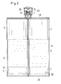
- Fig. 1 shows a first embodiment of the inventive cartridge 1, which serves for the metering of a multi-component filling compound 15.
- the cartridge 1 contains a storage chamber 5 (see Fig. 11 ), which consists of a first sub-chamber 6 for receiving a first component 8 and a second sub-chamber 7 for receiving a second component 9 of the filling compound 15.
- the storage chamber 5 has an outlet end 28 for discharging the filling compound 15 and a delivery end 29, which lies opposite the outlet end 28 and in Fig. 2 or Fig. 3 is visible.
- the storage chamber 5 thus extends according to Fig. 2 in the tubular portion between the conveyor end 29 and outlet end 28.
- the storage chamber 5 is surrounded by a housing 34, so that the filling material 15 can be accommodated in the storage chamber 5, as in Fig. 11 shown, or the two components 8, 9 can be accommodated in the corresponding first and second sub-chambers 6, 7.
- the storage chamber 5 includes a neck 2, in which an outlet channel 11, 12 is located.
- a first outlet channel 11 is shown, which is located within a second outlet channel 12.
- the first outlet channel 11 is thus arranged substantially coaxially to the second outlet channel 12, which is in Fig. 5 is best visible.
- the cartridge 7-10 opens into a corresponding outlet opening 10, 14.
- This outlet opening 10, 14 can be closed with a closure cap 13.
- the cartridge can with a in Fig. 3 or Fig. 11 be shown closed closure element on the delivery side 29.
- the closure element can be designed as a push-out element, for example as a piston 3, 4, which is displaceable in the storage chamber.
- Fig. 2 shows a side view of the cartridge 1 according to Fig. 1 for several components.
- the first partial chamber 6 is visible for a first component 8
- the second partial chamber is concealed.
- the sub-chambers may also have different volumes, if the mixing ratio deviates from a 1: 1 mixing ratio, that is, one of the sub-chambers may have a correspondingly larger volume than the other sub-chamber.
- Fig. 3 shows a front view of the cartridge, wherein the cartridge is shown partially cut. On the already related to Fig. 1 described parts of the cartridge will not be discussed further here.
- the sectional view clearly shows that the first sub-chamber 6 is separate from the second sub-chamber 7, so that the two components 8, 9 do not come into contact with each other.
- Such components usually interact with each other as soon as they come into contact with each other, whereby chemical reactions can take place.
- the interaction of the components is usually the effect that is needed in an application, however, this interaction is undesirable unless the components are used in the context of their particular application.
- the first sub-chamber 6 and the second sub-chamber 7 open into a respective outlet channel 11, 12 which is arranged in the interior of the neck 2 of the cartridge, as in Fig. 5 or 6 is shown.
- an ejection element 30 may be arranged in each of the subchambers 6, 7 in order to discharge the corresponding flowable component 8, 9 from the subchamber 6, 7.
- the push-out element 30 consists in Fig. 3 from a first piston 3 and a second piston 4. In Fig. 11 only the piston 3 is shown, which is provided for receiving in the storage chamber 5.
- the first piston 3 is movably receivable in the first sub-chamber 6 and the second piston 4 is movably receivable in the second sub-chamber 7, so that upon movement of at least one of the first or second piston 3,4, the first and second flowable component 8,9 simultaneously discharged are.
- the first piston 3 and the second piston 4 and the plunger, not shown, are integrally formed or are connected to each other at least via a coupling element such that they are simultaneously movable.
- the first and the second piston 3, 4 have at least one sealing element 41, which may be formed in particular as a sealing lip. In this way, a leakage of the components 8, 9 can be avoided, so that the components can be stored in the sub-chambers 6, 7.
- Fig. 4 shows a view of the neck 2 of a cartridge 1 according to one of Fig. 1 to 3 ,
- the neck 2 contains a first outlet channel 11 and a second outlet channel 12.
- the two outlet channels 11, 12 are used for the simultaneous discharge of the first component 8 and the second component 9.
- the neck 2 is surrounded by a shock absorbing element 20.
- the shock absorbing member 20 partially envelops the neck 2.
- the shock absorbing element 20 has a jacket 23. If the neck 2 and the shock absorbing element 20 are manufactured in one piece, for example by injection molding, a tool must be insertable within the shock absorbing element 20 for the preparation of the neck and any connecting elements in the space between the neck 2 and shock absorbing element. Therefore, the shock absorbing member includes at least one opening 26, which is preferably mounted in the jacket 23.
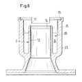
- Fig. 5 shows a section through the neck 2 of the multi-component cartridge according to Fig. 4 and Fig. 6 a section through the neck of a cartridge for a filling.
- the cartridge 1 comprises a storage chamber 5, 6, 7 for receiving a filling compound 8, 9, 15 and a neck 2, which contains an outlet channel 11, 12 for the filling compound 8, 9, 15, so that the filling compound 8, 9, 15 of FIG the storage chamber 5,6,7 through the outlet channel 11, 12 can be discharged.
- the filling material 8,9,15 exits through an outlet opening 10, 14 arranged at the end 16, 17 of the outlet channel 11, 12.
- the neck 2 is of the Shock absorbing member 20 is surrounded such that the shock absorbing member 20 has a first end 21 which is connected to the neck 2 and a second end 22 and the jacket 23 which extends between the first end 21 and second end 22, wherein the jacket 23rd and the second end 22 are arranged at a distance from the neck 2.
- the second end 22 projects beyond the neck 2, so that in the event of an impact only contact with the shock absorption element 20 occurs, but the neck 2 located underneath remains intact.
- a gap is formed in which a housing member 25, for example, a mixer housing 42 is receivable.
- the neck can also consist of a plurality of tubular nozzle according to a non-illustrated embodiment.
- a first and a second tubular stub are provided in each case.
- Each of the first and second tubular sockets may include first and second sealing members for receiving a first or second sump member, respectively.
- Each of the collecting elements passes into a mixer, which can be connected via the collecting element with the outlet channels of the cartridge.
- Such cartridges are for example in the EP 0 730 913 shown.
- the outlet channels may be arranged concentrically to each other, in this context, the term coaxial outlet is often used.
- the outlet channel 11 is located within the outlet channel 12.
- the outlet channel 12 thus surrounds the outlet channel 11 annular.
- Fig. 7 is a section through the neck of the cartridge according to Fig. 4 which is at 90 ° with respect to the section according to Fig. 5 is offset and which contains the longitudinal axis of the neck 2.
- the shock absorbing member 20 is formed integrally with the neck 2.
- the neck 2 contains a first outlet channel 11 and a second outlet channel 12.
- the first outlet channel 11 opens into a first outlet opening 10
- the second outlet channel 12 opens into a second outlet opening 14.
- the first outlet opening 10 is arranged at the first end 16 of the first outlet channel 11.
- the second outlet opening 14 is arranged at the second end 17 of the second outlet channel 12.
- a closure cap 13 is provided, by means of which each of the outlet openings 10, 14 can be closed.
- the closure cap includes a first receiving element 18 and a second receiving element 19. As shown in FIG Fig. 7 the first and second receiving elements 18, 19 are formed as grooves. These grooves serve to receive the respective ends 16, 17 of the outlet channels, when the closure cap 13 keeps the outlet channels 11, 12 closed.
- the closure cap 13 is connected to the cartridge 1, the neck 2 or the shock absorption element 20 by means of a connecting element 32.
- the closure cap 13 has an edge 35 which rests on a shoulder 36 of the shock absorption element 20 when the closure cap 13 is closed. The edge 35 may also rest on the neck 2 when the closure cap 13 is closed.
- the edge 35 does not touch the inner wall 47 of the shock absorbing element 20.
- the shock absorbing member 20 may deform without hindrance without transferring the deformation to the cap 13.
- the connecting element 32 may be formed in particular as a hinge element.
- the hinge element forms a permanent connection between the closure cap 13 and the cartridge 1, in particular its neck 2 or the shock absorption element 20, so that the closure cap remains permanently connected to the cartridge both in the opened and in the closed state.
- the connecting element 32 is elastic.
- the receiving element 18, 19 With the corresponding ends 16, 17 for Intervention brought.
- the receiving elements 18, 19 are preferably conical, so that by applying a low contact pressure, the ends 16, 17 are clamped in the receiving elements 18, 19 and keep the outlet openings so closed.
- the connecting element may have a constriction 46.
- This constriction is, for example, a dent or a groove, that is to say a region of the connecting element 32 which has a smaller wall thickness than the regions which adjoin the closure cap 13 or the cartridge 1 directly.
- the edge 35 advantageously has an outer diameter which is greater than the outer diameter of the neck 2. This ensures that the outer exit opening located at the outer closure can be held sealingly in the closure element 19 arranged near the edge when the closure cap is closed.
- the edge 35 is formed as a projection 39 which extends at least over part of the circumference of the closure cap 13.
- the projection 39 encloses the neck 2 at least partially.
- a fastener 40 is arranged, which can receive a tab 45 of the cap 13 to hold the cap 13 in the closed state.
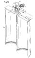
- Fig. 8 shows a side view of the neck of the cartridge according to Fig. 4 , In particular, show Fig. 8 and Fig. 9 in that the jacket 23 of the shock absorbing element 20 is arranged concentrically around the neck 2. Furthermore, the opening 26 in the jacket 23 is shown in this view.
- Fig. 9 shows a view of a cartridge with attached mixer
- Fig. 10 shows a section through a cartridge 1 with mounted mixer.
- the mixer 31 is disposed in the mixer housing 42 and is integral with executed the housing 34.
- the mixer 31 is designed in particular as a static mixer.
- the mixer housing 42 may each contain a corresponding sealing element, by means of which the corresponding outlet opening at the outlet end 28 of the cartridge can be closed.
- the mixer housing 42 may include a coupling element 43 which is intended for engagement with the neck 2.
- the coupling element 43 can be received in an engagement element 44 which surrounds the neck 2.
- the engagement member 44 is designed as part of the neck 2.
- the coupling member 43 can be displaced relative to the engagement member 44 so that the mixer housing is durable relative to the mixer and outlet end 28 either in a closed or open position.
- the mixer housing 42 is held in an open position during filling to allow air present in the first or second subchambers 6, 7 to escape via exit ports leading to the exit end 28.
- the mixer housing 42 is held in its open position as long as the filling is carried out in order to avoid that a pressure builds up in the first or second partial chamber 6, 7 which would make continued filling more difficult.
- the mixer housing 42 is moved to its closed position, in which the outlet openings of the outlet channels 11, 12 are kept closed.
- the first and second pistons 3, 4 are movable by means of a plunger 5 in order to discharge the two components 8, 9 at the same time.
- the plunger is in particular designed such that it rests on the first and the second piston 3,4.
- the plunger 27 is integrally connected in this embodiment with the piston 3.4.
- the mixer housing 42 is moved from its closed position to the open position. In this position, the outlet openings at the outlet end are in communication with the mixing chamber, which extends in the interior of the mixer housing.
- the first and second components 8, 9 and any air can be entered into the mixer. The air escapes in advance through the outlet opening of the mixer housing. Subsequently, the mixing of the first and second components 8, 9 takes place through the mixer 31.
- air which between the first or second piston 3, 4 and the Fill mass is included, may be provided on the corresponding piston or on the inner wall of the corresponding sub-chamber vent holes or vent grooves, in Fig. 5 are not shown.
- At least one of the storage chambers 5, 6, 7 can be at least partially transparent according to each of the exemplary embodiments, so that the filling level of the filling compound 8, 9, 15 in the corresponding storage chamber 5, 6, 7 can be controlled.
- the operation of the cartridge 1 comprises the steps of filling the cartridge 1 with a filling compound 8,9,15 and the discharge of the filling material.
- the outlet opening for the filling compound at the outlet end 28 of the cartridge may also be a ventilation opening 33.
- the cap 13 may contain vents or in combination with the neck 2 a Form vent opening.
- the size of the vent opening 33 can be adjustable, for example by providing a combination of a closure cap 13 with the neck 2, which has at least one conical surface.
- the distance between the closure cap 13 and the neck 2 in the region of the conical surface can be configured such that in the closed state, the conical surface closes the opening in a fluid-tight manner, allows a small amount of air to escape in a partially opened state, and leaves the outlet in the fully open position allowed a large amount of air or allows the exit of the filling material.
- a vent 33 may be provided on the piston 3.4.
- the vent may in this case comprise a membrane which releases an opening under pressure for the escape of air, or a vent valve which opens under pressure or under rest of the plunger.
- an opening or a groove can be provided on the inner wall of the housing or in the jacket area of the piston, which prevents the escape of air between the jacket area of the piston and the inner wall of the housing.
- the discharge of the filling compound 8,9,15 comprises the following steps: opening the closure cap 13 of the filled storage chamber 5,6,7 discharge the filling material 8,9,15 by being pressurized in the storage chamber 5,6,7, for which the push-out element 3, 4, 30 is shifted in such a way that the filling volume in the storage chamber 5, 6, 7 decreases.
- the vent opening which is in the open state, allow air, which is still trapped between the filling compound and the piston, can escape.
- a first flowable component and a second flowable component 8, 9 can be introduced into a first partial chamber 6 and a second partial chamber 7, and during discharge the first and second fluid components 8, 9 can be introduced from the first and second partial chambers 6, 7 emerge, each of the first and second piston 3,4 of a movable plunger 27 is displaced by applying a compressive force in the corresponding first or second partial chamber 6, 7 such that the filling volume in each of the first and second partial chambers 6, 7 decreases.
Landscapes
- Engineering & Computer Science (AREA)
- Mechanical Engineering (AREA)
- Closures For Containers (AREA)
- Containers And Packaging Bodies Having A Special Means To Remove Contents (AREA)
- Coating Apparatus (AREA)
- Package Specialized In Special Use (AREA)
Priority Applications (1)
| Application Number | Priority Date | Filing Date | Title |
|---|---|---|---|
| EP10177971A EP2314521A1 (de) | 2009-10-26 | 2010-09-21 | Kartusche mit integrierter Verschlusskappe |
Applications Claiming Priority (2)
| Application Number | Priority Date | Filing Date | Title |
|---|---|---|---|
| EP09174037 | 2009-10-26 | ||
| EP10177971A EP2314521A1 (de) | 2009-10-26 | 2010-09-21 | Kartusche mit integrierter Verschlusskappe |
Publications (1)
| Publication Number | Publication Date |
|---|---|
| EP2314521A1 true EP2314521A1 (de) | 2011-04-27 |
Family
ID=41800822
Family Applications (1)
| Application Number | Title | Priority Date | Filing Date |
|---|---|---|---|
| EP10177971A Withdrawn EP2314521A1 (de) | 2009-10-26 | 2010-09-21 | Kartusche mit integrierter Verschlusskappe |
Country Status (9)
| Country | Link |
|---|---|
| US (1) | US8657141B2 (pt) |
| EP (1) | EP2314521A1 (pt) |
| JP (1) | JP2011088672A (pt) |
| CN (1) | CN102050275B (pt) |
| AU (1) | AU2010224569A1 (pt) |
| BR (1) | BRPI1004241A2 (pt) |
| CA (1) | CA2714753A1 (pt) |
| RU (1) | RU2010143575A (pt) |
| TW (1) | TW201139226A (pt) |
Cited By (1)
| Publication number | Priority date | Publication date | Assignee | Title |
|---|---|---|---|---|
| EP2730341A1 (de) * | 2012-11-08 | 2014-05-14 | Sulzer Mixpac AG | Kartusche für mindestens zwei fliessfähige Komponenten |
Families Citing this family (5)
| Publication number | Priority date | Publication date | Assignee | Title |
|---|---|---|---|---|
| CA2746283A1 (en) * | 2010-09-10 | 2012-03-10 | Sulzer Mixpac Ag | Childproof closure for a dispensing apparatus |
| WO2013020597A1 (de) * | 2011-08-11 | 2013-02-14 | Henkel Ag & Co. Kgaa | Applikator für gelförmige wc-reinigungsprodukte direkt auf der oberfläche der wc-schüssel |
| ES2663728T3 (es) * | 2011-10-17 | 2018-04-16 | Sulzer Mixpac Ag | Cartucho, procedimiento para la fabricación de este, así como cartucho multicomponente |
| CN107399400B (zh) * | 2016-05-19 | 2021-10-22 | 光阳工业股份有限公司 | 二轮车辆的车体结构 |
| EP3632817A1 (en) * | 2018-10-02 | 2020-04-08 | Sulzer Mixpac AG | Cartridge, method of making a cartridge and method of using a cartridge |
Citations (9)
| Publication number | Priority date | Publication date | Assignee | Title |
|---|---|---|---|---|
| DE7425021U (de) * | 1974-07-23 | 1976-02-05 | Nova Handels Ag | Kindersicherer Verschluss |
| FR2623170A1 (fr) * | 1987-11-12 | 1989-05-19 | Tartaglione Andre | Procede de realisation d'un contenant plastique avec dispositif de bouchage et contenant plastique obtenu par ce procede |
| EP0587070A2 (de) * | 1992-09-04 | 1994-03-16 | Basf Lacke + Farben Ag | Mehrweg-Kartusche |
| DE4333812A1 (de) * | 1993-10-04 | 1995-04-06 | Falk Walter Schneider | Entsorgungshilfe für Kartuschen |
| DE4412907C1 (de) * | 1994-04-14 | 1995-08-24 | Automation Industrielle Sa | Verfahren zur Herstellung einer Tube aus Kunststoff und Tube aus Kunststoff |
| EP0873945A1 (en) * | 1997-04-25 | 1998-10-28 | Owens-Brockway Plastic Products Inc. | Multiple cavity dispensing package |
| US5829639A (en) * | 1996-10-31 | 1998-11-03 | Terry A. Horner | Flowable material dispenser with chambers |
| DE29906976U1 (de) * | 1999-04-20 | 2000-08-31 | Goldwell Gmbh | Zwillingsverpackung II |
| US20070007302A1 (en) * | 2005-07-08 | 2007-01-11 | Doraiswami Jaichandra | Device for dispensing a controlled dose of a flowable material |
Family Cites Families (7)
| Publication number | Priority date | Publication date | Assignee | Title |
|---|---|---|---|---|
| DE3011634A1 (de) * | 1980-03-26 | 1981-10-08 | Gerhart 3000 Hannover Daubner | Mehrkammer handspraydose mit verschliessbaren duesen, oder aushebbaren drehschieber |
| FR2633590B1 (fr) * | 1988-07-01 | 1990-11-02 | Astra Plastique | Bouchon-verseur en matiere synthetique a capuchon articule |
| US5020694A (en) | 1989-03-16 | 1991-06-04 | Chesebrough-Pond's, Inc. | Multi-cavity dispensing container |
| FR2652567B1 (fr) * | 1989-10-04 | 1992-01-10 | Oreal | Dispositif de distribution comportant au moins un flacon a embout cassable. |
| CH683417A5 (de) * | 1991-06-21 | 1994-03-15 | Createchnic Ag | Schnappscharnierverschluss mit Garantieband. |
| US7387220B2 (en) * | 2004-08-30 | 2008-06-17 | Scholle Corporation | Cap assembly and container used therewith |
| JP4276283B1 (ja) * | 2008-02-04 | 2009-06-10 | エム・エフ・ヴィ株式会社 | キャップ |
-
2010
- 2010-08-27 JP JP2010190664A patent/JP2011088672A/ja active Pending
- 2010-09-16 CA CA2714753A patent/CA2714753A1/en not_active Abandoned
- 2010-09-21 EP EP10177971A patent/EP2314521A1/de not_active Withdrawn
- 2010-09-30 AU AU2010224569A patent/AU2010224569A1/en not_active Abandoned
- 2010-10-13 US US12/925,134 patent/US8657141B2/en active Active
- 2010-10-21 TW TW099135986A patent/TW201139226A/zh unknown
- 2010-10-25 RU RU2010143575/12A patent/RU2010143575A/ru not_active Application Discontinuation
- 2010-10-25 BR BRPI1004241A patent/BRPI1004241A2/pt not_active Application Discontinuation
- 2010-10-25 CN CN201010526976.4A patent/CN102050275B/zh not_active Expired - Fee Related
Patent Citations (9)
| Publication number | Priority date | Publication date | Assignee | Title |
|---|---|---|---|---|
| DE7425021U (de) * | 1974-07-23 | 1976-02-05 | Nova Handels Ag | Kindersicherer Verschluss |
| FR2623170A1 (fr) * | 1987-11-12 | 1989-05-19 | Tartaglione Andre | Procede de realisation d'un contenant plastique avec dispositif de bouchage et contenant plastique obtenu par ce procede |
| EP0587070A2 (de) * | 1992-09-04 | 1994-03-16 | Basf Lacke + Farben Ag | Mehrweg-Kartusche |
| DE4333812A1 (de) * | 1993-10-04 | 1995-04-06 | Falk Walter Schneider | Entsorgungshilfe für Kartuschen |
| DE4412907C1 (de) * | 1994-04-14 | 1995-08-24 | Automation Industrielle Sa | Verfahren zur Herstellung einer Tube aus Kunststoff und Tube aus Kunststoff |
| US5829639A (en) * | 1996-10-31 | 1998-11-03 | Terry A. Horner | Flowable material dispenser with chambers |
| EP0873945A1 (en) * | 1997-04-25 | 1998-10-28 | Owens-Brockway Plastic Products Inc. | Multiple cavity dispensing package |
| DE29906976U1 (de) * | 1999-04-20 | 2000-08-31 | Goldwell Gmbh | Zwillingsverpackung II |
| US20070007302A1 (en) * | 2005-07-08 | 2007-01-11 | Doraiswami Jaichandra | Device for dispensing a controlled dose of a flowable material |
Cited By (2)
| Publication number | Priority date | Publication date | Assignee | Title |
|---|---|---|---|---|
| EP2730341A1 (de) * | 2012-11-08 | 2014-05-14 | Sulzer Mixpac AG | Kartusche für mindestens zwei fliessfähige Komponenten |
| US9611074B2 (en) | 2012-11-08 | 2017-04-04 | Sulzer Mixpac Ag | Cartridge for at least two flowable components |
Also Published As
| Publication number | Publication date |
|---|---|
| CN102050275A (zh) | 2011-05-11 |
| AU2010224569A1 (en) | 2011-05-12 |
| CN102050275B (zh) | 2015-02-25 |
| TW201139226A (en) | 2011-11-16 |
| RU2010143575A (ru) | 2012-04-27 |
| BRPI1004241A2 (pt) | 2015-12-15 |
| US8657141B2 (en) | 2014-02-25 |
| CA2714753A1 (en) | 2011-04-26 |
| JP2011088672A (ja) | 2011-05-06 |
| US20110095026A1 (en) | 2011-04-28 |
Similar Documents
| Publication | Publication Date | Title |
|---|---|---|
| EP2218518B1 (de) | Mehrkomponentenkartusche zur einmaligen Verwendung | |
| EP2314522B1 (de) | Behälter mit einem stossabsorbierenden Element | |
| EP2497721B1 (de) | Mehrkomponentenkartusche | |
| EP2396237B1 (de) | Austragvorrichtung mit tube | |
| EP0313519B1 (de) | Einrichtung zum Dosieren und Mischen von mindestens zwei Reaktionskomponenten | |
| EP1140259B1 (de) | Mehrkammer-ampulle zum ausgeben eines aus mehreren substanzen bestehenden gemisches | |
| EP2428282B1 (de) | Kartuschenkolben | |
| DE202005001203U1 (de) | Mehrkomponentenfolienbehälter | |
| DE112007003620B4 (de) | Chemikalienmischbehälter mit elastischer Trennwand | |
| EP2410940B1 (de) | Spritze zur einmaligen verwendung | |
| EP2314521A1 (de) | Kartusche mit integrierter Verschlusskappe | |
| EP1676791B1 (de) | Mehrkammerkartusche für mehrkomponentige plastische Massen mit axial hintereinander angeordneten Kammern | |
| DE10114624B4 (de) | Druckdose und ihre Verwendung für 2-Komponentensysteme | |
| WO2005124204A2 (de) | Verschluss für einen behälter | |
| WO2011073251A1 (de) | Kartusche mit verschlussstopfen | |
| DE102016122041A1 (de) | Mehrkomponentenbehältnis | |
| EP2158136B1 (de) | Vorrichtung zum austragen einer fliessfähigen substanz | |
| DE7631034U1 (de) | Vorrichtung zur Abgabe mindestens zweier fliessfaehiger Stoffe in vermischter Form aus einem Behaelter mittels Treibgas | |
| WO2010145889A1 (de) | Mehrkomponentenkartusche zur einmaligen verwendung | |
| DE1952006C3 (de) | Vorrichtung zum Dosieren von Zweikomponenten-Kunststoffvorprodukten | |
| DE10234435A1 (de) | Mit Fluidwerkstoffen gefüllte Kartusche und Vorrichtung zum Laden einer solchen Kartusche in eine Fluidabgabevorrichtung | |
| EP2443045B1 (de) | Mehrkomponentenkartusche mit entlüftungsvorrichtung | |
| DE2808230C2 (de) | Spritz-Kartusche | |
| DE4430713B4 (de) | Kartusche | |
| EP4190192A1 (de) | Flüssigkeitsspender und flüssigkeitskartuschen für einen solchen flüssigkeitsspender |
Legal Events
| Date | Code | Title | Description |
|---|---|---|---|
| PUAI | Public reference made under article 153(3) epc to a published international application that has entered the european phase |
Free format text: ORIGINAL CODE: 0009012 |
|
| AK | Designated contracting states |
Kind code of ref document: A1 Designated state(s): AL AT BE BG CH CY CZ DE DK EE ES FI FR GB GR HR HU IE IS IT LI LT LU LV MC MK MT NL NO PL PT RO SE SI SK SM TR |
|
| AX | Request for extension of the european patent |
Extension state: BA ME RS |
|
| 17P | Request for examination filed |
Effective date: 20111027 |
|
| 17Q | First examination report despatched |
Effective date: 20130207 |
|
| STAA | Information on the status of an ep patent application or granted ep patent |
Free format text: STATUS: THE APPLICATION HAS BEEN WITHDRAWN |
|
| 18W | Application withdrawn |
Effective date: 20130425 |