EP2313940B1 - Séparateur d'accumulateur renforcé - Google Patents
Séparateur d'accumulateur renforcé Download PDFInfo
- Publication number
- EP2313940B1 EP2313940B1 EP09752015.9A EP09752015A EP2313940B1 EP 2313940 B1 EP2313940 B1 EP 2313940B1 EP 09752015 A EP09752015 A EP 09752015A EP 2313940 B1 EP2313940 B1 EP 2313940B1
- Authority
- EP
- European Patent Office
- Prior art keywords
- ribs
- separator
- major
- battery
- rib
- Prior art date
- Legal status (The legal status is an assumption and is not a legal conclusion. Google has not performed a legal analysis and makes no representation as to the accuracy of the status listed.)
- Active
Links
- 239000000463 material Substances 0.000 claims description 23
- 238000004519 manufacturing process Methods 0.000 claims description 11
- 239000011149 active material Substances 0.000 description 20
- 238000000034 method Methods 0.000 description 15
- 239000002253 acid Substances 0.000 description 11
- 239000003792 electrolyte Substances 0.000 description 11
- 239000000203 mixture Substances 0.000 description 10
- 239000000945 filler Substances 0.000 description 9
- 238000013461 design Methods 0.000 description 8
- 239000004014 plasticizer Substances 0.000 description 7
- QAOWNCQODCNURD-UHFFFAOYSA-N Sulfuric acid Chemical compound OS(O)(=O)=O QAOWNCQODCNURD-UHFFFAOYSA-N 0.000 description 6
- 239000012530 fluid Substances 0.000 description 6
- YADSGOSSYOOKMP-UHFFFAOYSA-N lead dioxide Inorganic materials O=[Pb]=O YADSGOSSYOOKMP-UHFFFAOYSA-N 0.000 description 6
- 229920000098 polyolefin Polymers 0.000 description 6
- -1 polypropylenes Polymers 0.000 description 6
- 238000001035 drying Methods 0.000 description 5
- 238000003860 storage Methods 0.000 description 5
- 239000000758 substrate Substances 0.000 description 5
- 229910000978 Pb alloy Inorganic materials 0.000 description 4
- VYPSYNLAJGMNEJ-UHFFFAOYSA-N Silicium dioxide Chemical compound O=[Si]=O VYPSYNLAJGMNEJ-UHFFFAOYSA-N 0.000 description 4
- TZCXTZWJZNENPQ-UHFFFAOYSA-L barium sulfate Chemical compound [Ba+2].[O-]S([O-])(=O)=O TZCXTZWJZNENPQ-UHFFFAOYSA-L 0.000 description 4
- 229920001577 copolymer Polymers 0.000 description 4
- 239000011148 porous material Substances 0.000 description 4
- XLYOFNOQVPJJNP-UHFFFAOYSA-N water Substances O XLYOFNOQVPJJNP-UHFFFAOYSA-N 0.000 description 4
- 239000004698 Polyethylene Substances 0.000 description 3
- 238000010924 continuous production Methods 0.000 description 3
- 229910003460 diamond Inorganic materials 0.000 description 3
- 239000010432 diamond Substances 0.000 description 3
- 239000011262 electrochemically active material Substances 0.000 description 3
- HTUMBQDCCIXGCV-UHFFFAOYSA-N lead oxide Chemical compound [O-2].[Pb+2] HTUMBQDCCIXGCV-UHFFFAOYSA-N 0.000 description 3
- 239000002184 metal Substances 0.000 description 3
- 229910052751 metal Inorganic materials 0.000 description 3
- 238000012986 modification Methods 0.000 description 3
- 230000004048 modification Effects 0.000 description 3
- 239000004745 nonwoven fabric Substances 0.000 description 3
- 229920000573 polyethylene Polymers 0.000 description 3
- 239000004800 polyvinyl chloride Substances 0.000 description 3
- 229920000915 polyvinyl chloride Polymers 0.000 description 3
- KEQXNNJHMWSZHK-UHFFFAOYSA-L 1,3,2,4$l^{2}-dioxathiaplumbetane 2,2-dioxide Chemical compound [Pb+2].[O-]S([O-])(=O)=O KEQXNNJHMWSZHK-UHFFFAOYSA-L 0.000 description 2
- NLZUEZXRPGMBCV-UHFFFAOYSA-N Butylhydroxytoluene Chemical compound CC1=CC(C(C)(C)C)=C(O)C(C(C)(C)C)=C1 NLZUEZXRPGMBCV-UHFFFAOYSA-N 0.000 description 2
- LFQSCWFLJHTTHZ-UHFFFAOYSA-N Ethanol Chemical compound CCO LFQSCWFLJHTTHZ-UHFFFAOYSA-N 0.000 description 2
- 239000004743 Polypropylene Substances 0.000 description 2
- 229910045601 alloy Inorganic materials 0.000 description 2
- 239000000956 alloy Substances 0.000 description 2
- 239000003963 antioxidant agent Substances 0.000 description 2
- 230000000712 assembly Effects 0.000 description 2
- 238000000429 assembly Methods 0.000 description 2
- 230000015572 biosynthetic process Effects 0.000 description 2
- 239000006229 carbon black Substances 0.000 description 2
- 150000004649 carbonic acid derivatives Chemical class 0.000 description 2
- 238000005266 casting Methods 0.000 description 2
- 239000003086 colorant Substances 0.000 description 2
- 238000009749 continuous casting Methods 0.000 description 2
- 230000008878 coupling Effects 0.000 description 2
- 238000010168 coupling process Methods 0.000 description 2
- 238000005859 coupling reaction Methods 0.000 description 2
- 238000009826 distribution Methods 0.000 description 2
- 238000001125 extrusion Methods 0.000 description 2
- 239000007789 gas Substances 0.000 description 2
- 239000011521 glass Substances 0.000 description 2
- 230000001965 increasing effect Effects 0.000 description 2
- 229910000464 lead oxide Inorganic materials 0.000 description 2
- 239000011859 microparticle Substances 0.000 description 2
- 238000002156 mixing Methods 0.000 description 2
- 239000012466 permeate Substances 0.000 description 2
- 229920000642 polymer Polymers 0.000 description 2
- 229920001155 polypropylene Polymers 0.000 description 2
- 238000005096 rolling process Methods 0.000 description 2
- 150000003839 salts Chemical class 0.000 description 2
- 238000000926 separation method Methods 0.000 description 2
- 239000000377 silicon dioxide Substances 0.000 description 2
- 239000003381 stabilizer Substances 0.000 description 2
- 238000005406 washing Methods 0.000 description 2
- HXIQYSLFEXIOAV-UHFFFAOYSA-N 2-tert-butyl-4-(5-tert-butyl-4-hydroxy-2-methylphenyl)sulfanyl-5-methylphenol Chemical compound CC1=CC(O)=C(C(C)(C)C)C=C1SC1=CC(C(C)(C)C)=C(O)C=C1C HXIQYSLFEXIOAV-UHFFFAOYSA-N 0.000 description 1
- CDOUZKKFHVEKRI-UHFFFAOYSA-N 3-bromo-n-[(prop-2-enoylamino)methyl]propanamide Chemical compound BrCCC(=O)NCNC(=O)C=C CDOUZKKFHVEKRI-UHFFFAOYSA-N 0.000 description 1
- OYPRJOBELJOOCE-UHFFFAOYSA-N Calcium Chemical compound [Ca] OYPRJOBELJOOCE-UHFFFAOYSA-N 0.000 description 1
- OKTJSMMVPCPJKN-UHFFFAOYSA-N Carbon Chemical compound [C] OKTJSMMVPCPJKN-UHFFFAOYSA-N 0.000 description 1
- 239000004215 Carbon black (E152) Substances 0.000 description 1
- 239000004593 Epoxy Chemical class 0.000 description 1
- 229910019142 PO4 Inorganic materials 0.000 description 1
- 229920000297 Rayon Polymers 0.000 description 1
- GHMLBKRAJCXXBS-UHFFFAOYSA-N Resorcinol Natural products OC1=CC=CC(O)=C1 GHMLBKRAJCXXBS-UHFFFAOYSA-N 0.000 description 1
- DBMJMQXJHONAFJ-UHFFFAOYSA-M Sodium laurylsulphate Chemical compound [Na+].CCCCCCCCCCCCOS([O-])(=O)=O DBMJMQXJHONAFJ-UHFFFAOYSA-M 0.000 description 1
- 229920002522 Wood fibre Polymers 0.000 description 1
- 150000001242 acetic acid derivatives Chemical class 0.000 description 1
- 230000002378 acidificating effect Effects 0.000 description 1
- 239000000654 additive Substances 0.000 description 1
- 239000000853 adhesive Substances 0.000 description 1
- 230000001070 adhesive effect Effects 0.000 description 1
- 230000002411 adverse Effects 0.000 description 1
- PNEYBMLMFCGWSK-UHFFFAOYSA-N aluminium oxide Inorganic materials [O-2].[O-2].[O-2].[Al+3].[Al+3] PNEYBMLMFCGWSK-UHFFFAOYSA-N 0.000 description 1
- 229910052924 anglesite Inorganic materials 0.000 description 1
- 230000003078 antioxidant effect Effects 0.000 description 1
- 238000010923 batch production Methods 0.000 description 1
- 229940077388 benzenesulfonate Drugs 0.000 description 1
- 235000010354 butylated hydroxytoluene Nutrition 0.000 description 1
- 229910052791 calcium Inorganic materials 0.000 description 1
- 239000011575 calcium Substances 0.000 description 1
- 230000015556 catabolic process Effects 0.000 description 1
- 238000006243 chemical reaction Methods 0.000 description 1
- 239000002817 coal dust Substances 0.000 description 1
- 239000011248 coating agent Substances 0.000 description 1
- 238000000576 coating method Methods 0.000 description 1
- 238000002485 combustion reaction Methods 0.000 description 1
- 150000001875 compounds Chemical class 0.000 description 1
- 238000010276 construction Methods 0.000 description 1
- 239000013078 crystal Substances 0.000 description 1
- 238000006731 degradation reaction Methods 0.000 description 1
- 230000008021 deposition Effects 0.000 description 1
- 239000003989 dielectric material Substances 0.000 description 1
- 235000019329 dioctyl sodium sulphosuccinate Nutrition 0.000 description 1
- 238000007598 dipping method Methods 0.000 description 1
- 238000007599 discharging Methods 0.000 description 1
- 239000000428 dust Substances 0.000 description 1
- 229920001971 elastomer Polymers 0.000 description 1
- 230000005611 electricity Effects 0.000 description 1
- 238000003487 electrochemical reaction Methods 0.000 description 1
- 239000008151 electrolyte solution Substances 0.000 description 1
- 238000004049 embossing Methods 0.000 description 1
- 230000002708 enhancing effect Effects 0.000 description 1
- 239000000835 fiber Substances 0.000 description 1
- 238000011049 filling Methods 0.000 description 1
- 235000013312 flour Nutrition 0.000 description 1
- SLGWESQGEUXWJQ-UHFFFAOYSA-N formaldehyde;phenol Chemical compound O=C.OC1=CC=CC=C1 SLGWESQGEUXWJQ-UHFFFAOYSA-N 0.000 description 1
- 239000000499 gel Substances 0.000 description 1
- 239000010439 graphite Substances 0.000 description 1
- 229910002804 graphite Inorganic materials 0.000 description 1
- 230000005484 gravity Effects 0.000 description 1
- 229930195733 hydrocarbon Natural products 0.000 description 1
- 150000002430 hydrocarbons Chemical class 0.000 description 1
- 150000004679 hydroxides Chemical class 0.000 description 1
- 229910052500 inorganic mineral Inorganic materials 0.000 description 1
- 150000002500 ions Chemical class 0.000 description 1
- 239000006233 lamp black Substances 0.000 description 1
- 229920005610 lignin Polymers 0.000 description 1
- 230000003137 locomotive effect Effects 0.000 description 1
- 238000012423 maintenance Methods 0.000 description 1
- 238000002844 melting Methods 0.000 description 1
- 230000008018 melting Effects 0.000 description 1
- 229910000000 metal hydroxide Inorganic materials 0.000 description 1
- 229910044991 metal oxide Inorganic materials 0.000 description 1
- 150000004706 metal oxides Chemical class 0.000 description 1
- 229910052914 metal silicate Inorganic materials 0.000 description 1
- 239000011707 mineral Substances 0.000 description 1
- 239000007773 negative electrode material Substances 0.000 description 1
- 150000002823 nitrates Chemical class 0.000 description 1
- 150000002895 organic esters Chemical class 0.000 description 1
- 239000002245 particle Substances 0.000 description 1
- 238000005192 partition Methods 0.000 description 1
- 239000006072 paste Substances 0.000 description 1
- 239000008188 pellet Substances 0.000 description 1
- 229920001568 phenolic resin Polymers 0.000 description 1
- 125000001997 phenyl group Chemical group [H]C1=C([H])C([H])=C(*)C([H])=C1[H] 0.000 description 1
- 235000021317 phosphate Nutrition 0.000 description 1
- 150000003013 phosphoric acid derivatives Chemical class 0.000 description 1
- 150000003014 phosphoric acid esters Chemical class 0.000 description 1
- 229920001083 polybutene Polymers 0.000 description 1
- 229920000728 polyester Polymers 0.000 description 1
- 239000007774 positive electrode material Substances 0.000 description 1
- 239000000047 product Substances 0.000 description 1
- 229920005989 resin Polymers 0.000 description 1
- 239000011347 resin Substances 0.000 description 1
- 238000012552 review Methods 0.000 description 1
- 238000007789 sealing Methods 0.000 description 1
- 239000011734 sodium Substances 0.000 description 1
- 229910052708 sodium Inorganic materials 0.000 description 1
- 235000019333 sodium laurylsulphate Nutrition 0.000 description 1
- 239000002904 solvent Substances 0.000 description 1
- 239000000126 substance Substances 0.000 description 1
- 238000006467 substitution reaction Methods 0.000 description 1
- 150000003467 sulfuric acid derivatives Chemical class 0.000 description 1
- 238000012360 testing method Methods 0.000 description 1
- 229920005992 thermoplastic resin Polymers 0.000 description 1
- 239000000080 wetting agent Substances 0.000 description 1
- 239000002023 wood Substances 0.000 description 1
- 239000002025 wood fiber Substances 0.000 description 1
- 239000010457 zeolite Substances 0.000 description 1
Images


Classifications
-
- H—ELECTRICITY
- H01—ELECTRIC ELEMENTS
- H01M—PROCESSES OR MEANS, e.g. BATTERIES, FOR THE DIRECT CONVERSION OF CHEMICAL ENERGY INTO ELECTRICAL ENERGY
- H01M10/00—Secondary cells; Manufacture thereof
- H01M10/06—Lead-acid accumulators
- H01M10/12—Construction or manufacture
-
- H—ELECTRICITY
- H01—ELECTRIC ELEMENTS
- H01M—PROCESSES OR MEANS, e.g. BATTERIES, FOR THE DIRECT CONVERSION OF CHEMICAL ENERGY INTO ELECTRICAL ENERGY
- H01M10/00—Secondary cells; Manufacture thereof
- H01M10/06—Lead-acid accumulators
- H01M10/12—Construction or manufacture
- H01M10/14—Assembling a group of electrodes or separators
-
- H—ELECTRICITY
- H01—ELECTRIC ELEMENTS
- H01M—PROCESSES OR MEANS, e.g. BATTERIES, FOR THE DIRECT CONVERSION OF CHEMICAL ENERGY INTO ELECTRICAL ENERGY
- H01M50/00—Constructional details or processes of manufacture of the non-active parts of electrochemical cells other than fuel cells, e.g. hybrid cells
- H01M50/40—Separators; Membranes; Diaphragms; Spacing elements inside cells
- H01M50/463—Separators, membranes or diaphragms characterised by their shape
-
- Y—GENERAL TAGGING OF NEW TECHNOLOGICAL DEVELOPMENTS; GENERAL TAGGING OF CROSS-SECTIONAL TECHNOLOGIES SPANNING OVER SEVERAL SECTIONS OF THE IPC; TECHNICAL SUBJECTS COVERED BY FORMER USPC CROSS-REFERENCE ART COLLECTIONS [XRACs] AND DIGESTS
- Y02—TECHNOLOGIES OR APPLICATIONS FOR MITIGATION OR ADAPTATION AGAINST CLIMATE CHANGE
- Y02E—REDUCTION OF GREENHOUSE GAS [GHG] EMISSIONS, RELATED TO ENERGY GENERATION, TRANSMISSION OR DISTRIBUTION
- Y02E60/00—Enabling technologies; Technologies with a potential or indirect contribution to GHG emissions mitigation
- Y02E60/10—Energy storage using batteries
-
- Y—GENERAL TAGGING OF NEW TECHNOLOGICAL DEVELOPMENTS; GENERAL TAGGING OF CROSS-SECTIONAL TECHNOLOGIES SPANNING OVER SEVERAL SECTIONS OF THE IPC; TECHNICAL SUBJECTS COVERED BY FORMER USPC CROSS-REFERENCE ART COLLECTIONS [XRACs] AND DIGESTS
- Y02—TECHNOLOGIES OR APPLICATIONS FOR MITIGATION OR ADAPTATION AGAINST CLIMATE CHANGE
- Y02T—CLIMATE CHANGE MITIGATION TECHNOLOGIES RELATED TO TRANSPORTATION
- Y02T10/00—Road transport of goods or passengers
- Y02T10/60—Other road transportation technologies with climate change mitigation effect
- Y02T10/70—Energy storage systems for electromobility, e.g. batteries
Definitions
- the present application relates to the field of batteries (e.g., lead-acid batteries including batteries for vehicle starting, lighting, and ignition applications; marine batteries; commercial batteries; industrial batteries; batteries for use with hybrid-electric vehicles, microhybrid vehicles, etc.).
- batteries e.g., lead-acid batteries including batteries for vehicle starting, lighting, and ignition applications; marine batteries; commercial batteries; industrial batteries; batteries for use with hybrid-electric vehicles, microhybrid vehicles, etc.
- the present application relates to battery separators. More particularly, it relates to a separator of varying thickness with areas of increased thickness near shoulders of the separator.
- the invention relates to a battery separator including a backweb of separator material having a backweb thickness, at least one major rib projecting beyond the backweb thickness a first distance, and at least one sub-major rib projecting beyond the backweb thickness a second distance wherein the first distance is greater than the second distance and wherein the ribs are approximately evenly spaced.
- This invention also relates to this battery separator including a backweb of separator material with a plurality of approximately evenly spaced ribs, a shoulder with shoulder mini-rubs, and a sub-major rib on each shoulder.
- Another exemplary embodiment relates to a battery including at least one anode, at least one cathode, and at least one separator, as it is claimed in claim 1, wherein the separator includes a backweb of separator material with major ribs and sub-major ribs and wherein the ribs are approximately evenly spaced.
- This separator further includes a shoulder with shoulder mini-rubs, and a sub-major rib on each shoulder.
- Another exemplary embodiment relates to a method of manufacturing battery separators, as claimed in claim 1, of different sizes comprising: forming a backweb of separator material with an odd number of ribs including a center rib wherein the separator is symmetrical about the center rib and the spacing of ribs to either side of the center rib is the same for all separators regardless of separator size.
- FIG. 1 is an isometric view of a vehicle including a battery according to an exemplary embodiment
- FIG. 2 is an isometric cut-away view of a portion of a battery and its components according to an exemplary embodiment
- FIG. 3 is a front plan cut-away view of a battery plate or electrode (e.g., positive battery plate) including a stamped grid and active material according to an exemplary embodiment;
- a battery plate or electrode e.g., positive battery plate
- FIG. 3 is a front plan cut-away view of a battery plate or electrode (e.g., positive battery plate) including a stamped grid and active material according to an exemplary embodiment
- FIG. 4 is a front plan view of a stamped grid (e.g., positive grid) according to an exemplary embodiment
- FIG. 5 is an isometric exploded view of a battery plate or electrode (e.g., negative battery plate) and separator according to an exemplary embodiment
- FIG. 6 is an isometric view of a separator according to a first exemplary embodiment
- FIG. 7 is an isometric view of a separator according to a second exemplary embodiment.
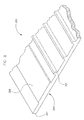
- FIG. 8 is a partial isometric view of a separator according to a third exemplary embodiment
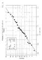
- FIG. 9 is a probability plot tracking cold crank performance for a battery with standard separators
- FIG. 10 is a probability plot tracking cold crank performance for a battery with a separator according to an exemplary embodiment.
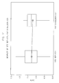
- FIG. 11 is a boxplot comparing the cold crank performance of the batteries illustrated in FIGS. 9 and 10 .
- a vehicle 140 that includes a battery 100 according to an exemplary embodiment. While vehicle 140 is shown as an automobile, according to various alternative embodiments, vehicle 140 may include any variety of types of vehicles including, among others, motorcycles, buses, recreational vehicles, boats, and the like. According to an exemplary embodiment, vehicle 140 uses an internal combustion engine for locomotive purposes.
- Battery 100 shown in FIG. 1 is configured to provide at least a portion of the power required to start or operate the vehicle and/or various vehicle systems (e.g., starting, lighting, and ignition systems). Further, it should be understood that battery 100 may be utilized in a variety of applications not involving a vehicle, and all such applications are intended to be within the scope of the present disclosure.
- the battery shown in FIG. 1 may include any type of secondary battery (e.g., rechargeable battery).
- battery 100 is a lead-acid storage battery.
- lead-acid storage batteries may be sealed (e.g., non-maintenance) or unsealed (e.g., wet).
- Battery 100 is illustrated in FIG. 2 .
- battery 100 includes several cell elements which are provided in separate compartments of a container or housing 110 containing electrolyte.
- the illustrations provided herein relate to automotive applications, wherein groups of 12-16 plates are used in each of six stacks for producing a standard automotive 12-volt battery. It will be apparent to those skilled in the art after reading this specification that the size and number of the individual plates, the size and number of plates in any particular stack, and the number of stacks used to construct the battery may vary widely depending upon the desired end use.
- housing 110 includes a box-like base or container and may be made of a moldable resin.
- a plurality of plate blocks are connected in series according to the capacity of the lead storage battery and are accommodated in the battery container or housing 110 together with the electrolyte, which is commonly aqueous sulfuric acid.
- the battery includes a compartment having a front wall, end walls, a rear wall, and a bottom wall.
- five cell partitions or dividers are provided between the end walls, resulting in the formation of six compartments, as typically would be present in a twelve volt automotive battery.
- a plate block is located in each compartment, each plate block including one or more positive plates 101 and negative plates 102, each having at least one lug 103, and separator 420 placed between each positive plate 101 and negative plate 102.
- Cover 111 is provided for the housing 110 and, in various embodiments, cover 111 includes terminal bushings and fill tubes to allow electrolyte to be added to the cells and to permit servicing. To prevent undesirable spillage of electrolyte from the fill tubes, and to permit exhausting of gases generated during the electrochemical reaction, a battery may also include one or more filler hole caps and/or vent cap assemblies.
- At least one positive terminal post 104 and at least one negative terminal post 105 may be found on or about the top or front compartments of battery 100.
- Such terminal posts 104 and 105 typically include portions which may extend through the cover and/or the front of the battery housing 110, depending upon the battery design.
- the terminal posts also extend through a terminal post seal assembly to help prevent leakage of acid. It will be recognized that a variety of terminal arrangements are possible, including top, side, or corner configurations known in the art.
- FIG. 2 also shows a conventional cast-on strap 106 which includes a rectangular, elongated body portion of a length sufficient to electrically couple each lug 103 in a plate set and an upwardly extending member having a rounded top.
- FIG. 2 also illustrates a cast-on-strap 106 coupling lugs 103 to a negative terminal 105.
- the strap 106 includes a body portion coupling the respective lugs 103 in the end compartments and a post formed therewith that may protrude through a cover.
- Each cell element or chapter includes at least one positive plate 101, at least one negative plate 102, and a separator 420 positioned between each positive plate 101 and negative plate 102. Separators 420 are provided between the plates 101 and 102 to prevent shorting and undesirable electron flow produced during the reaction occurring in the battery 100.
- Positive electrode plates 101 and negative electrode plates 102 can be classified into various types according to the method of manufacturing the same.
- a paste type electrode is shown in FIGS. 3-5 .
- the paste type electrode includes a grid 107 substrate and an electrochemically active material or "paste" provided on the substrate.
- the grid 107 may be formed of a soft alloy containing a trace of calcium for enhancing the mechanical strength of the substrate.
- plates each comprise a lead or lead alloy grid 107 that supports an electrochemically active material.
- Grids 107 provide an electrical contact between the positive and negative active materials or paste which serves to conduct current.
- Grids 107 also serve as a substrate for helping support electrochemically active material (e.g., paste) deposited or otherwise provided thereon during manufacture to form the battery plates.
- known arts of lead acid battery grid making include: (1) batch processes such as book mold gravity casting; and (2) continuous processes such as strip expansion, strip stamping, continuous casting, and continuous casting followed by rolling. Grids made from these processes tend to have unique features characteristic of the particular process and behave differently in lead acid batteries, especially with respect to the pasting process. It should be appreciated that grids formed from any conventional or later-developed grid manufacturing process may be utilized, and it is not the intent to limit the invention to the grid design disclosed herein.
- FIG. 3 illustrates an exemplary embodiment of a stamped grid 107 (e.g., a grid for a positive plate) with active material or paste provided thereon.
- FIG. 4 illustrates the stamped grid 107 shown in FIG. 3 , but without active material.
- stamped grid includes a frame that includes a top frame element, first and second side frame elements, and a bottom frame element.
- the stamped grid includes a series of grid wires that define open areas that help hold the active material or paste that helps provides current generation.
- a current collection lug 103 is integral with the top frame element. While FIGS.
- lug 103 as offset from the center of the top frame element, the lug may alternatively be centered or positioned closer to either the first or second side frame elements.
- the top frame element may include an enlarged conductive section at least a portion of which is directly beneath the lug to optimize current conduction to the lug.
- the bottom frame element may be formed with one or more downwardly extending feet (not shown) for spacing the remainder of the stamped grid away from the bottom of the battery container.
- at least some of the wires of the stamped grid increase in cross-sectional area along their length from bottom to top and/or have a tapered shape so as to optimize the current carrying capacity of the wires to help carry current being generated from the bottom to the top.
- the width and spacing of the wires between side elements may be predetermined so that there are substantially equal potential points across the width of the stamped grid.
- the stamped grid also includes horizontal wires which are equally spaced apart and are parallel to the top and/or bottom frame elements. As shown in FIG. 3-4 , however, at least some of the horizontal wires may not be equally spread apart or parallel to the top and/or bottom frame elements.
- an expanded metal grid (e.g., a grid for the negative plate) is illustrated in FIG. 5 .
- the expanded metal grid has a pattern (e.g., a diamond pattern such as that shown in FIG. 5 ), which is well known in the art, with a bottom frame element, and a top frame element that is integral with a lug 103.
- the cross-section of the grid wires may vary depending upon the grid making process.
- the grid wires may be mechanically reshaped or refinished.
- any number of grid wire shapes may be utilized as long as the shape provides suitable paste adhesion characteristics.
- the cross section of wires may be of any cross-section design including substantially oval shaped, substantially rectangular, substantially diamond shape, substantially rhomboid shape, substantially hexagon shape, and/or substantially octagon shape.
- each grid wire section may have a different cross-sectional configuration, or each grid wire section may have the same or a similar cross-sectional configuration. However, it is preferred that each grid wire section have the same cross-sectional configuration.
- grid 107 can be deformed at the vertical wire elements only, the horizontal wire elements only, or at both the vertical and horizontal wire elements.
- the active material or paste is typically a lead-based material (e.g., PbO, PbO 2 Pb or PbSO 4 at different charge/discharge stages of the battery) that is pasted, deposited or otherwise provided onto grids 107.
- the paste composition may be determined by power requirements, cost, and battery environment, as it is known in the art.
- the active material of a lead-acid battery is prepared by mixing lead oxide, sulfuric acid, and water.
- the lead oxide reacts with the sulfuric acid to form mono-, tri-, and/or tetra-basic lead sulfate(s).
- Dry additives, such as fiber and expander, may also be added to the active material.
- expanders such as finely-divided carbons (e.g., lampblack or carbon black), barium sulfate, and various lignins may be included in the active material.
- the mixture is then dried and water is re-added to form a paste of the desired consistency.
- the active material provided on a positive grid e.g., lead dioxide [PbO 2 ]
- a positive grid e.g., lead dioxide [PbO 2 ]
- PbO 2 lead dioxide
- the spongy lead, the active material of the negative electrode plate, is typically porous and reactive, so that the electrolyte is allowed to diffuse and permeate through the sponge lead on the negative electrode plate.
- a pasting paper (not shown) may be adhered or otherwise provided on at least one of the surfaces of the active material as a support to the active material after deposition on the grids.
- Porous nonwoven fabric e.g., having micron-sized pores
- a nonwoven fabric synthesized from thermoplastic resin by spun-bonding or thermal-bonding may be used.
- nonwoven fabric formed of one or more polyesters, polypropylenes, or viscose rayons are used.
- one or more battery separators 420 are used to conductively separate the positive electrode plates 101 and negative electrode plates 102.
- the separator material is typically microporous to allow the through passage of ions from the positive electrode plates 101 and negative electrode plates 102.
- separators 420 for automotive batteries are typically made in continuous lengths and rolled, subsequently folded as shown in FIG. 5 , and sealed along one or more of their edges to form pouches that receive a battery plate (e.g., a negative plate as shown in FIG. 5 or a positive plate as shown in FIG. 2 ).
- one or more separators 420 may be folded such that the ribs line the interior of the pouch that is formed to receive a battery plate.
- separator material generally has a substantially uniform thickness and a substantially uniform pore distribution.
- the pore distribution helps ensure an overall uniform current density during operation, thereby helping achieving a uniform charging and discharging of the electrodes and maximum battery efficiency.
- Separator 420 generally incorporates one or more ribs (e.g., as shown in FIG. 5 ) to help stiffen the separator 420.
- the ribs can have various cross-sectional shapes (e.g. rectangular, triangular, rounded, saw-tooth) or combination there.
- references to the orientation and placement of features generally are taken from the perspective of an end view.
- the disclosed separators generally feature one or more raised ribs that run lengthwise along the separator.
- a separator according to various exemplary embodiments, has at least one raised rib and two shoulders.
- separator 120 includes a number of major ribs 121 and sub-major ribs 122.
- Conventional ribbed separators typically include relatively smaller mini-ribs rather than sub-major ribs 122.
- Conventional mini-ribs are typically about 0.15 mm high (unless noted otherwise, the stated height of the various ribs is measured from the top of the separator backweb, i.e., the face of the backweb closest the distal position of the ribs or the face of the backweb on which the ribs are provided).
- sub-major ribs 122 are 0.45 mm to 0.60 mm in height.
- the relatively taller sub-major ribs 122 function better at keeping the electrode plates away from the separator backweb than conventional mini-ribs.
- the various ribs are generally parallel to one another.
- major ribs 121 are 0.60 mm to 1.90 mm in height.
- the ratio of major rib height to sub-major rib height may be as high as about 4.25:1 and is greater than 1:1 (e.g., 4:3).
- the size of the major ribs is generally determined by the spacing required between electrode plates to accommodate the proper amount of acid and/or to fill the space in a battery compartment.
- the separator has an odd number of major ribs 121 (e.g., seven major ribs) and the ribs are symmetrically placed such that a single major rib divides the separator into two relatively equally-dimensioned halves.
- the separator is fed by rollers through a folding machine to form envelopes into which an electrode is placed, such as in FIG. 5 .
- Conventional separators have a variable profile in that the spacing of major ribs and mini-ribs varies across different size separators. Separators with varying profiles can be difficult to use in battery manufacturing because they will tend to drift in the rollers to fit into grooves that form in the rollers over time because of the separators uneven surfaces.
- separator 120 has three sub-major ribs 122 substantially evenly-spaced between each of major-ribs 121.
- separator 120 has seven major ribs 121 and six sets of three sub-major ribs 122 between each of the seven major ribs 121.
- the separator includes a shoulder 124, i.e., the area on each side of the separator 120 between separator edge 127 and the nearest major rib.
- Conventional separators typically include a plurality of shoulder mini-ribs that are about 0.10 mm high.
- Shoulder 124 has a plurality of enhanced shoulder mini-ribs 125 and/or at least one sub-major rib 122.
- the shoulder mini-ribs 125 have a height greater than 0.10 mm (e.g., about 0.15 mm) and one or more sub-major ribs, having a greater height than the should mini-ribs 125.
- a separator 220 includes a number of major ribs 221 (e.g., larger ribs), sub-major ribs 222 (e.g., intermediate sized ribs), and mini-ribs 223 (e.g., smaller ribs).
- the various types are generally parallel to one another and/or evenly spaced apart at least between the shoulders.
- the spacing of major ribs 221, sub-major ribs 222, and mini-ribs 223 are kept identical to improve tracking during battery manufacturing.
- Separator 220 also preferably has an odd number of major ribs 221, which aids separator tracking.
- sub-major ribs 122 are 0.45 mm to 0.60 mm in height.
- a separator 220 has two sub-major ribs 222 and three mini-ribs 223 between major ribs 221. In such embodiments, every other rib is a mini-rib 223. In the exemplary embodiment of FIG. 7 , between the shoulders there are seven major ribs 221, twelve sub-major ribs 222, and eighteen mini-ribs 223. In various exemplary embodiments, separator shoulder 224 may include at least one sub-major rib or a mini rib or mini-rib 222, respectively, similar to sub-major rib 122 shown in FIG. 7 .
- a separator includes a shoulder 224, which is defined as the area on either side of the separator 220 between a separator edge 227 and nearest major rib 221.
- Conventional separators typically include a plurality of shoulder mini-ribs that are about 0.10 mm in height.
- separator 220 has a shoulder 224 with a plurality of enhanced shoulder mini-ribs 225 and/or at least one sub-major rib 222.
- the shoulder mini-ribs 225 have a height greater than 0.10 mm (e.g. about 0.1 5 mm).
- separator 320 includes a backweb (e.g., a sheet or bracket) of dielectric material with at least one raised rib 321.
- separator 320 also includes a shoulder 324 between rib 321 closest to an edge of separator 320 and the edge.
- certain ribs 321 are typically substantially evenly-spaced between shoulders across width of separator 320 and run lengthwise.
- shoulder 324 includes a raised portion 326 that is relatively thicker than other one or more portions of shoulder 324.
- raised portion 326 is typically shorter in height and wider than any of the ribs 321.
- raised portion 326 does not extend to the edge of separator 320 or to nearest rib 321. Thus, in such embodiments, there is an area between the edge and raised portion 326 that is not raised or otherwise is substantially identical in thickness.
- the width and position of the raised portion 326 may vary depending on factors including the geometry of the electrode plates.
- the raised portion 326 is sized and positioned so as to cover areas where punctures are most likely to occur, and perhaps without covering any additional areas.
- raised portion 326 is tapered at least, e.g. at one or more of its edges.
- the edge of raised portion 326 angles away of an angle to the separator 320 surface. In one exemplary embodiment, angle is about 45 degrees.
- one or more sides of the ribs 321 are also sloped. In various embodiments, sides of the ribs 321 slope at a steeper angle than the raised portion 326. For example, in various embodiments, angle of the side of rib 321 may be seven degrees from vertical to the separator surface.
- the width of thickened portion 326 on shoulder 324 is less than the width of shoulder 324.
- a separator 120 with all of the shoulder raised i.e., the width of the raised portion is the same or nearly the same as that of the shoulder) minimizes piercing of the separator at the shoulder, but may adversely affect cold crank performance (depending on how much of the thickened separator is over the face of the electrode plate.
- the edge of the separator tends to become wavy and more difficult to roll.
- less than all of shoulder 324 is raised (or made thicker).
- the separator may be constructed of a variety of materials (e.g., polyolefin, rubber, phenol-formaldehyde resorcinol, glass mat, microporous PVC, and sintered PVC).
- the separator is constructed of at least in part of a microporous backweb comprised of high molecular weight polyolefin.
- polyolefins that may be used include polyethylene, polypropylene, polybutene, ethylene-propylene copolymers, ethylene-butene copolymers, propylene-butene copolymers, and ethylene-propylene-butene copolymers.
- the separator also includes at least one plasticizer.
- the plasticizer may be soluble or insoluble in water.
- plasticizers include organic esters, epoxy compounds, phosphate esters, hydrocarbon materials, and low molecular weight polymers.
- the separator is also constructed of an inert filler material.
- the filler can be soluble or insoluble in water.
- the filler may provide the primary means by which any plasticizer is absorbed and held in the composition and should not be soluble in the plasticizer.
- the preferred filler is dry, finely divided silica.
- fillers e.g., carbon black; coal dust; graphite; metal oxides and hydroxides; metal carbonates; minerals; zeolites; precipitated metal silicates; alumina silica gels; wood flour, wood fibers, and bark products; glass particles; salts such as barium sulfate; inorganic salts; acetates; sulfates; phosphates; nitrates; carbonates; and/or combinations thereof
- fillers e.g., carbon black; coal dust; graphite; metal oxides and hydroxides; metal carbonates; minerals; zeolites; precipitated metal silicates; alumina silica gels; wood flour, wood fibers, and bark products; glass particles; salts such as barium sulfate; inorganic salts; acetates; sulfates; phosphates; nitrates; carbonates; and/or combinations thereof
- barium sulfate inorganic salts
- wetting agents e.g., sodium alkyl benzene sulfonate, sodium lauryl sulfate, dioctyl sodium sulfosuccinate, and isoctyl phenyl polyethoxy ethanol
- any known or later-developed wetting agents e.g., sodium alkyl benzene sulfonate, sodium lauryl sulfate, dioctyl sodium sulfosuccinate, and isoctyl phenyl polyethoxy ethanol
- the separator includes a stabilizer or an antioxidant.
- conventional stabilizers or antioxidants such as 4,4 thiobis (6-tert-butyl-m-cresol) (“Santonox”), and 2,6-di-tert-butyl-4-methylphenol (“Ionol”) may be utilized.
- the ribs may be formed from a number of known or later-developed polymeric compositions (e.g., the same composition as the separator, other polyolefins, polyvinyl chloride, and/or filled or foamed compositions thereof).
- the ribs may be provided in any number of ways.
- the ribs may be formed by extrusion (either unitarily with the backweb sheet or separately).
- the ribs may also be formed by grooving or embossing.
- ribs When ribs are molded separately, they may be bonded or otherwise coupled to the backweb sheet or base web by any number of methods known in the art including heat sealing or by an adhesive.
- the thickness of a separator will vary depending upon the type of battery in which it is used. In general, the thickness of the backweb or base web can range from 1 to 50 milli-inches ("mils"). (1 mil is 0.0254mm). For lead-acid batteries, the preferred thickness range is typically 10 to 40 mils.
- the height of each rib may vary over a wide range depending upon plate spacing requirements. Generally, ribs from 5 to 200 mils in height from the base are provided, with the preferred range being 10 to 100 mils.
- a plate for a lead-acid battery is conventionally made by applying active material or paste to a conductive support such as a lead alloy grid. Plates can be classified according to the method of manufacturing the same. For example, one process for producing battery plates includes an initial step of melting hot lead in a furnace, followed by a step of feeding molten lead alloy to a strip caster. In the strip expansion process, a cast or wrought lead strip is typically pierced, stretched above and below the strip plane, and then pulled or expanded to form a grid with a diamond pattern. In various embodiments, the strip is coiled on a winder, and coils of lead alloy strip are stored for later use. In various embodiments, the strip may also be rolled. To form a battery grid, in various embodiments, the strip is fed through an expander that cuts, slits, and stretches a strip of coil to form the grids.
- the grids may be produced using other known or later-developed processes.
- the substrate may be formed by a casting process (e.g., by pouring a melted alloy into a mold), a stamping process, or by continuous rolling.
- the grid wires may be refinished or reshaped (e.g., to improve adhesion of the paste).
- the active material or paste is then applied to or otherwise provided (e.g., pasted by a conventional paster) on the expanded strip or wire grid.
- one or more pasting materials or pasting papers are provided on one or both surfaces of the active material.
- the pasting materials or paper may be provided in a continuous process.
- the grids, active material, and pasting material or paper are fed to a divider where the strip is cut into plates. Plates cut from the strip may be flattened or otherwise modified to help smooth out any uneven regions of paste.
- the plates pass (e.g., on a conveyor) through an oven for flash-drying, and may then be stacked for later use. Conventionally, flash-drying may be performed using an open gas flame or an oven, e.g., as a 10-15 second drying of the plates in a conventional blast drying oven at about 260 deg C (about 500 deg F). After drying, the battery plates undergo a chemical treatment, well known to those skilled in the art.
- the pasted plates are next typically cured for many hours under elevated temperature and humidity to help oxidize any free lead and otherwise adjust the crystal structure of the plate.
- Conventional polyolefin battery separators are typically produced by a process that comprises blending a composition of high molecular weight polyolefin, an inert filler material, and/or a plasticizer, forming the composition into sheet form, and subsequently extracting a portion of the inert filler and/or plasticizer from the backweb sheet using a solvent.
- the plates are assembled into batteries.
- Groupings of individual battery plates may be assembled, enveloped, interleaved, or otherwise separated with separator material, and provided together to form plate sets.
- every other plate (e.g., each negative plate) in the battery set is inserted into a battery separator in the form of an envelope.
- the envelope acts as a separator between the plate in the envelope and the adjoining plates in the battery set.
- the plate sets are assembled in a container to help form a battery.
- the positive lugs of the battery plates are coupled together and the negative lugs of the battery plates are coupled together.
- This is typically accomplished using cast-on straps formed by taking assembled battery stacks, inverting them, and dipping the lugs into molten lead provided in a mold. To permit current to follow throughout the battery, cast-on straps of stacks are joined or coupled.
- terminal electrodes are provided which extend through the cover or casing to permit electrical contact with a vehicle's electrical system or other system requiring or intended to use battery power.
- the battery housing 110 including the cover 111, is provided containing the battery cells.
- the battery housing 110 is submerged in acidic electrolyte fluid in order to fill the battery housing 110 with electrolyte fluid through fill tube holes in the battery cover 111.
- the battery 100 is removed from the electrolyte fluid. Any residual electrolyte fluid coating, dust, and other debris may be washed away to prepare the battery for shipment.
- the fill tube holes may be plugged to prevent washing fluid from entering the battery housing.
- a single separator 120 may be folded around an electrode plate 101 or 102, such as illustrated in FIG. 5 .
- one or more aligned edges of the separator may be joined to form an envelope of separator material into which an electrode plate may be inserted and/or sealed with a tab or lug protruding therefrom.
- one or the other of the positive electrode plates or negative electrode plates are encased in separator material with the other placed between envelopes to create a pattern similar to that exemplified by FIG. 2 .
- the separator may be manufactured in various known or later-developed methods (e.g., extrusion).
- the separator is manufactured by extruding a mixture of a polymer, such as polyethylene, and an oil. After the mixture is extruded, the oil is extracted leaving micro-pores throughout the separator, which makes it permeable to the electrolyte solution.
- the separator is manufactured in a continuous process and rolled into large coils for ease of storage and handling.
- a microporous polyethylene separator according to the embodiment of FIG. 8 was tested.
- the backweb of tested separator was 0.006 in. (0.15 mm) thick.
- the separator was 6.400 inches in width with 17 ribs running along its length.
- the ribs were 0.029 in. (0.74 mm) high (not including the separator backweb thickness) and about 0.015 in. (0.38 mm) wide at their peak width.
- the ribs were spaced about 0.313 in. (7.94 mm) apart (measured from rib centers).
- the separator shoulders were 0.700 in.
- the raised portion of the shoulder was 0.360 in. (9.14 mm) wide and 0.011 in (0.28 mm) thick (including the thickness of the separator backweb).
- the raised portion is located 0.120 in. (3.05 mm) from the center of the nearest rib and 0.220 in. (5.59 mm) from the edge.
- FIG. 9 is a probability plot tracking cold crank performance for a battery with standard separators.
- FIG. 10 is a probability plot tracking cold crank performance for a battery with a separator according to an exemplary embodiment.
- FIG. 11 is a boxplot comparing the cold crank performance of the batteries illustrated in FIGS. 9 and 10 .
- the experimental data show that the use of the disclosed separator did not have a statistically significant impact on cold crank performance.
- the tests showed that the use of the separator did not have a statistically significant impact on cold crank performance.
- elements shown as integrally formed may be constructed of multiple parts or elements shown as multiple parts may be integrally formed, the operation of the interfaces may be reversed or otherwise varied, the length or width of the structures and/or members or connector or other elements of the system may be varied, the nature or number of adjustment positions provided between the elements may be varied (e.g., by variations in the number of engagement slots or size of the engagement slots or type of engagement).
- the elements and/or assemblies of the system may be constructed from any of a wide variety of colors, textures, and combinations. Accordingly, all such modifications are intended to be within the scope of the present inventions. Other substitutions, modifications, changes, or omissions may be made in the design, operating conditions, and arrangement of the preferred and other exemplary embodiments without departing from the present invention.
Claims (14)
- Séparateur d'accumulateur comprenant :un tissu envers en matériau de séparateur ayant une épaisseur de tissu envers ;un certain nombre de nervures principales saillant au-delà de l'épaisseur de tissu envers sur une première distance ;au moins une première nervure secondaire prévue entre les nervures principales et saillant au-delà de l'épaisseur de tissu envers sur une seconde distance ; etune zone d'épaulement prévue entre un bord du tissu envers et la nervure principale la plus proche, la zone d'épaulement ayant une seconde nervure secondaire saillant au-delà de l'épaisseur de tissu envers sur la seconde distance et une pluralité de mini-nervures d'épaulement améliorées saillant au-delà de l'épaisseur de tissu envers sur une troisième distance ;dans lequel la première distance est supérieure à la seconde distance, la seconde distance est supérieure à la troisième distance et les nervures principales et les premières nervures secondaires sont espacées de façon régulière sur le tissu envers.
- Séparateur d'accumulateur selon la revendication 1, dans lequel trois nervures secondaires sont prévues entre les nervures principales.
- Séparateur d'accumulateur selon la revendication 1, dans lequel deux nervures secondaires et trois mini-nervures espacées de façon régulière sont prévues entre les nervures principales, chaque mini-nervure saillant au-delà de l'épaisseur de tissu envers sur la troisième distance.
- Séparateur d'accumulateur selon la revendication 3, dans lequel chaque autre nervure prévue entre les nervures principales est une mini-nervure.
- Séparateur d'accumulateur selon l'une quelconque des revendications 1 à 4, dans lequel la seconde distance va de 0,45 mm à 0,60 mm.
- Séparateur d'accumulateur selon l'une quelconque des revendications 1 à 5, dans lequel la première distance va de 0,60 mm à 1,90 mm.
- Séparateur d'accumulateur selon l'une quelconque des revendications 1 à 6, dans lequel il y a un nombre impair de nervures principales.
- Séparateur d'accumulateur selon la revendication 7, dans lequel il y a sept nervures principales.
- Séparateur d'accumulateur selon l'une quelconque des revendications 1 à 8, dans lequel une nervure principale s'étend le long du centre du séparateur.
- Séparateur d'accumulateur selon l'une quelconque des revendications 1 à 9, dans lequel les mini-nervures d'épaulement saillent d'environ 0,15 mm au-delà de l'épaisseur de tissu envers.
- Séparateur d'accumulateur selon l'une quelconque des revendications 1 à 8, dans lequel la zone d'épaulement comprend une partie relevée saillant au-delà de l'épaisseur de tissu envers et une partie ne saillant pas au-delà de l'épaisseur de tissu envers prévue entre la partie relevée et le bord du tissu envers en matériau de séparateur.
- Séparateur d'accumulateur selon la revendication 11, dans lequel la partie relevée a un bord effilé ayant une pente inférieure à la pente d'une nervure.
- Séparateur d'accumulateur selon l'une quelconque des revendications 11 ou 12, dans lequel la partie relevée saille au-delà de l'épaisseur de tissu envers sur une quatrième distance, la quatrième distance étant inférieure à la troisième distance.
- Procédé de fabrication de séparateurs d'accumulateur selon la revendication 1, comprenant :la formation d'un tissu envers en matériau de séparateur avec un nombre impair de nervures comprenant une nervure principale centrale, dans lequel le séparateur est symétrique par rapport à la nervure principale centrale et l'espacement des nervures par rapport à un côté ou l'autre de la nervure principale centrale est le même pour tous les séparateurs indépendamment de la taille du séparateur.
Applications Claiming Priority (2)
| Application Number | Priority Date | Filing Date | Title |
|---|---|---|---|
| US7961208P | 2008-07-10 | 2008-07-10 | |
| PCT/US2009/050278 WO2010011507A1 (fr) | 2008-07-10 | 2009-07-10 | Séparateur d'accumulateur renforcé |
Publications (2)
| Publication Number | Publication Date |
|---|---|
| EP2313940A1 EP2313940A1 (fr) | 2011-04-27 |
| EP2313940B1 true EP2313940B1 (fr) | 2013-05-29 |
Family
ID=41396282
Family Applications (1)
| Application Number | Title | Priority Date | Filing Date |
|---|---|---|---|
| EP09752015.9A Active EP2313940B1 (fr) | 2008-07-10 | 2009-07-10 | Séparateur d'accumulateur renforcé |
Country Status (8)
| Country | Link |
|---|---|
| US (1) | US9799871B2 (fr) |
| EP (1) | EP2313940B1 (fr) |
| JP (1) | JP5504261B2 (fr) |
| CN (2) | CN104218206B (fr) |
| BR (1) | BRPI0915543B1 (fr) |
| CA (2) | CA2730341C (fr) |
| MX (1) | MX2011000406A (fr) |
| WO (1) | WO2010011507A1 (fr) |
Cited By (1)
| Publication number | Priority date | Publication date | Assignee | Title |
|---|---|---|---|---|
| CN105848969A (zh) * | 2014-01-02 | 2016-08-10 | 约翰逊控制技术公司 | 用于车辆的微混合动力电池模块 |
Families Citing this family (13)
| Publication number | Priority date | Publication date | Assignee | Title |
|---|---|---|---|---|
| EP2568545A1 (fr) * | 2010-11-12 | 2013-03-13 | Samsung Electronics Co., Ltd. | Connecteur et dispositif dýinterface |
| EP2783405B1 (fr) * | 2011-11-21 | 2020-04-15 | Daramic, LLC | Séparateurs gaufrés, batteries et procédés associés |
| CN104584270B (zh) * | 2012-08-22 | 2017-07-18 | 达拉米克有限责任公司 | 用于铅酸电池的具有凝胶浸渍非织造物的电池隔板 |
| DE102013111667A1 (de) * | 2013-10-23 | 2015-04-23 | Johnson Controls Autobatterie Gmbh & Co. Kgaa | Gitteranordnung für eine plattenförmige Batterieelektrode und Akkumulator |
| KR101422815B1 (ko) * | 2013-12-31 | 2014-07-28 | (주)영남유리산업 | 유리창 고정막대 고정구조의 스테인리스 단열창호 프레임 |
| US10014501B2 (en) | 2014-03-22 | 2018-07-03 | Hollingsworth & Vose Company | Battery separators having a low apparent density |
| US10230088B1 (en) * | 2015-01-30 | 2019-03-12 | Johnson Controls Technology Company | Battery electrode assembly, separator and method of making same |
| US10270074B2 (en) | 2015-02-19 | 2019-04-23 | Hollingsworth & Vose Company | Battery separators comprising chemical additives and/or other components |
| DE112016002044T5 (de) * | 2015-05-05 | 2018-03-01 | Daramic, Llc | Verbesserte Separatoren für VRLA-Batterien und damit in Beziehung stehende Verfahren |
| WO2017123190A1 (fr) * | 2016-01-11 | 2017-07-20 | Daramic, Llc | Séparateurs de batterie améliorés pour cyclopousse et batteries au plomb de véhicule similaire |
| WO2018174871A1 (fr) * | 2017-03-22 | 2018-09-27 | Daramic, Llc | Séparateurs améliorés et batteries au plomb, procédés et systèmes associés |
| CN112340815B (zh) * | 2019-08-06 | 2023-08-25 | 无锡小天鹅电器有限公司 | 电解组件、电解装置及衣物处理设备 |
| WO2022155234A1 (fr) * | 2021-01-12 | 2022-07-21 | Cps Technology Holdings Llc | Électrode pour batterie au plomb et batterie au plomb comprenant celle-ci |
Family Cites Families (7)
| Publication number | Priority date | Publication date | Assignee | Title |
|---|---|---|---|---|
| JPH02160365A (ja) * | 1989-10-26 | 1990-06-20 | Matsushita Electric Ind Co Ltd | 鉛蓄電池用袋状セパレータの製造法 |
| JPH052369U (ja) * | 1991-06-26 | 1993-01-14 | 日本無機株式会社 | 鉛蓄電池用リブ付きセパレータ |
| US20030129486A1 (en) * | 1999-08-11 | 2003-07-10 | Werner Bohnstedt | Battery separator provided with a plurality of studs and vertical ribs |
| JP5025865B2 (ja) * | 2001-09-28 | 2012-09-12 | 日本板硝子株式会社 | 鉛蓄電池用リブ付きセパレータ |
| US6641954B2 (en) * | 2002-03-29 | 2003-11-04 | Entek International Llc | Battery separator with mud rest protectors |
| US7425387B2 (en) * | 2003-08-09 | 2008-09-16 | Daramic, Inc. | Separator for a lead storage battery |
| DE102006014691B3 (de) * | 2006-03-28 | 2007-08-16 | Vb Autobatterie Gmbh & Co. Kgaa | Bleiakkumulator und Separator hierzu |
-
2009
- 2009-07-10 WO PCT/US2009/050278 patent/WO2010011507A1/fr active Application Filing
- 2009-07-10 JP JP2011517655A patent/JP5504261B2/ja active Active
- 2009-07-10 US US13/003,517 patent/US9799871B2/en active Active
- 2009-07-10 CN CN201410409009.8A patent/CN104218206B/zh active Active
- 2009-07-10 CN CN200980134354.2A patent/CN102144318B/zh active Active
- 2009-07-10 CA CA2730341A patent/CA2730341C/fr active Active
- 2009-07-10 BR BRPI0915543-0A patent/BRPI0915543B1/pt active IP Right Grant
- 2009-07-10 MX MX2011000406A patent/MX2011000406A/es active IP Right Grant
- 2009-07-10 EP EP09752015.9A patent/EP2313940B1/fr active Active
- 2009-07-10 CA CA2829590A patent/CA2829590C/fr active Active
Cited By (2)
| Publication number | Priority date | Publication date | Assignee | Title |
|---|---|---|---|---|
| CN105848969A (zh) * | 2014-01-02 | 2016-08-10 | 约翰逊控制技术公司 | 用于车辆的微混合动力电池模块 |
| CN105848969B (zh) * | 2014-01-02 | 2019-01-11 | 约翰逊控制技术公司 | 用于车辆的微混合动力电池模块 |
Also Published As
| Publication number | Publication date |
|---|---|
| JP5504261B2 (ja) | 2014-05-28 |
| CA2730341A1 (fr) | 2010-01-28 |
| CA2829590C (fr) | 2014-08-19 |
| CA2829590A1 (fr) | 2010-01-28 |
| EP2313940A1 (fr) | 2011-04-27 |
| US20110177375A1 (en) | 2011-07-21 |
| CN102144318B (zh) | 2014-09-24 |
| JP2011527822A (ja) | 2011-11-04 |
| CN102144318A (zh) | 2011-08-03 |
| US9799871B2 (en) | 2017-10-24 |
| MX2011000406A (es) | 2011-03-30 |
| BRPI0915543A2 (pt) | 2016-01-26 |
| CN104218206A (zh) | 2014-12-17 |
| BRPI0915543B1 (pt) | 2019-11-12 |
| CN104218206B (zh) | 2018-01-23 |
| CA2730341C (fr) | 2013-12-10 |
| WO2010011507A1 (fr) | 2010-01-28 |
Similar Documents
| Publication | Publication Date | Title |
|---|---|---|
| EP2313940B1 (fr) | Séparateur d'accumulateur renforcé | |
| US10205157B2 (en) | Electrode for lead acid storage battery | |
| US8846252B2 (en) | Battery electrode and method for manufacturing same | |
| US9130232B2 (en) | Battery grids and methods for manufacturing same | |
| US8586248B2 (en) | Battery, battery plate assembly, and method of assembly | |
| US8993151B2 (en) | Battery having non-planar heat seal with extended container walls and recessed cover walls | |
| US11824204B2 (en) | Battery and battery plate assembly with absorbent separator | |
| US9153802B2 (en) | Secondary battery | |
| US10355264B2 (en) | Secondary battery |
Legal Events
| Date | Code | Title | Description |
|---|---|---|---|
| PUAI | Public reference made under article 153(3) epc to a published international application that has entered the european phase |
Free format text: ORIGINAL CODE: 0009012 |
|
| 17P | Request for examination filed |
Effective date: 20110207 |
|
| AK | Designated contracting states |
Kind code of ref document: A1 Designated state(s): AT BE BG CH CY CZ DE DK EE ES FI FR GB GR HR HU IE IS IT LI LT LU LV MC MK MT NL NO PL PT RO SE SI SK SM TR |
|
| AX | Request for extension of the european patent |
Extension state: AL BA RS |
|
| DAX | Request for extension of the european patent (deleted) | ||
| 17Q | First examination report despatched |
Effective date: 20120522 |
|
| GRAP | Despatch of communication of intention to grant a patent |
Free format text: ORIGINAL CODE: EPIDOSNIGR1 |
|
| GRAS | Grant fee paid |
Free format text: ORIGINAL CODE: EPIDOSNIGR3 |
|
| GRAA | (expected) grant |
Free format text: ORIGINAL CODE: 0009210 |
|
| AK | Designated contracting states |
Kind code of ref document: B1 Designated state(s): AT BE BG CH CY CZ DE DK EE ES FI FR GB GR HR HU IE IS IT LI LT LU LV MC MK MT NL NO PL PT RO SE SI SK SM TR |
|
| REG | Reference to a national code |
Ref country code: GB Ref legal event code: FG4D |
|
| REG | Reference to a national code |
Ref country code: CH Ref legal event code: EP |
|
| REG | Reference to a national code |
Ref country code: AT Ref legal event code: REF Ref document number: 614895 Country of ref document: AT Kind code of ref document: T Effective date: 20130615 |
|
| REG | Reference to a national code |
Ref country code: IE Ref legal event code: FG4D |
|
| REG | Reference to a national code |
Ref country code: DE Ref legal event code: R096 Ref document number: 602009016021 Country of ref document: DE Effective date: 20130725 |
|
| REG | Reference to a national code |
Ref country code: AT Ref legal event code: MK05 Ref document number: 614895 Country of ref document: AT Kind code of ref document: T Effective date: 20130529 |
|
| REG | Reference to a national code |
Ref country code: LT Ref legal event code: MG4D |
|
| PG25 | Lapsed in a contracting state [announced via postgrant information from national office to epo] |
Ref country code: LT Free format text: LAPSE BECAUSE OF FAILURE TO SUBMIT A TRANSLATION OF THE DESCRIPTION OR TO PAY THE FEE WITHIN THE PRESCRIBED TIME-LIMIT Effective date: 20130529 Ref country code: NO Free format text: LAPSE BECAUSE OF FAILURE TO SUBMIT A TRANSLATION OF THE DESCRIPTION OR TO PAY THE FEE WITHIN THE PRESCRIBED TIME-LIMIT Effective date: 20130829 Ref country code: GR Free format text: LAPSE BECAUSE OF FAILURE TO SUBMIT A TRANSLATION OF THE DESCRIPTION OR TO PAY THE FEE WITHIN THE PRESCRIBED TIME-LIMIT Effective date: 20130830 Ref country code: IS Free format text: LAPSE BECAUSE OF FAILURE TO SUBMIT A TRANSLATION OF THE DESCRIPTION OR TO PAY THE FEE WITHIN THE PRESCRIBED TIME-LIMIT Effective date: 20130929 Ref country code: PT Free format text: LAPSE BECAUSE OF FAILURE TO SUBMIT A TRANSLATION OF THE DESCRIPTION OR TO PAY THE FEE WITHIN THE PRESCRIBED TIME-LIMIT Effective date: 20130930 Ref country code: ES Free format text: LAPSE BECAUSE OF FAILURE TO SUBMIT A TRANSLATION OF THE DESCRIPTION OR TO PAY THE FEE WITHIN THE PRESCRIBED TIME-LIMIT Effective date: 20130909 Ref country code: SE Free format text: LAPSE BECAUSE OF FAILURE TO SUBMIT A TRANSLATION OF THE DESCRIPTION OR TO PAY THE FEE WITHIN THE PRESCRIBED TIME-LIMIT Effective date: 20130529 Ref country code: AT Free format text: LAPSE BECAUSE OF FAILURE TO SUBMIT A TRANSLATION OF THE DESCRIPTION OR TO PAY THE FEE WITHIN THE PRESCRIBED TIME-LIMIT Effective date: 20130529 Ref country code: SI Free format text: LAPSE BECAUSE OF FAILURE TO SUBMIT A TRANSLATION OF THE DESCRIPTION OR TO PAY THE FEE WITHIN THE PRESCRIBED TIME-LIMIT Effective date: 20130529 Ref country code: FI Free format text: LAPSE BECAUSE OF FAILURE TO SUBMIT A TRANSLATION OF THE DESCRIPTION OR TO PAY THE FEE WITHIN THE PRESCRIBED TIME-LIMIT Effective date: 20130529 |
|
| REG | Reference to a national code |
Ref country code: NL Ref legal event code: VDEP Effective date: 20130529 |
|
| PG25 | Lapsed in a contracting state [announced via postgrant information from national office to epo] |
Ref country code: HR Free format text: LAPSE BECAUSE OF FAILURE TO SUBMIT A TRANSLATION OF THE DESCRIPTION OR TO PAY THE FEE WITHIN THE PRESCRIBED TIME-LIMIT Effective date: 20130529 Ref country code: PL Free format text: LAPSE BECAUSE OF FAILURE TO SUBMIT A TRANSLATION OF THE DESCRIPTION OR TO PAY THE FEE WITHIN THE PRESCRIBED TIME-LIMIT Effective date: 20130529 Ref country code: BG Free format text: LAPSE BECAUSE OF FAILURE TO SUBMIT A TRANSLATION OF THE DESCRIPTION OR TO PAY THE FEE WITHIN THE PRESCRIBED TIME-LIMIT Effective date: 20130829 |
|
| PG25 | Lapsed in a contracting state [announced via postgrant information from national office to epo] |
Ref country code: LV Free format text: LAPSE BECAUSE OF FAILURE TO SUBMIT A TRANSLATION OF THE DESCRIPTION OR TO PAY THE FEE WITHIN THE PRESCRIBED TIME-LIMIT Effective date: 20130529 |
|
| PG25 | Lapsed in a contracting state [announced via postgrant information from national office to epo] |
Ref country code: SK Free format text: LAPSE BECAUSE OF FAILURE TO SUBMIT A TRANSLATION OF THE DESCRIPTION OR TO PAY THE FEE WITHIN THE PRESCRIBED TIME-LIMIT Effective date: 20130529 Ref country code: EE Free format text: LAPSE BECAUSE OF FAILURE TO SUBMIT A TRANSLATION OF THE DESCRIPTION OR TO PAY THE FEE WITHIN THE PRESCRIBED TIME-LIMIT Effective date: 20130529 Ref country code: BE Free format text: LAPSE BECAUSE OF FAILURE TO SUBMIT A TRANSLATION OF THE DESCRIPTION OR TO PAY THE FEE WITHIN THE PRESCRIBED TIME-LIMIT Effective date: 20130529 Ref country code: CZ Free format text: LAPSE BECAUSE OF FAILURE TO SUBMIT A TRANSLATION OF THE DESCRIPTION OR TO PAY THE FEE WITHIN THE PRESCRIBED TIME-LIMIT Effective date: 20130529 Ref country code: DK Free format text: LAPSE BECAUSE OF FAILURE TO SUBMIT A TRANSLATION OF THE DESCRIPTION OR TO PAY THE FEE WITHIN THE PRESCRIBED TIME-LIMIT Effective date: 20130529 |
|
| PG25 | Lapsed in a contracting state [announced via postgrant information from national office to epo] |
Ref country code: NL Free format text: LAPSE BECAUSE OF FAILURE TO SUBMIT A TRANSLATION OF THE DESCRIPTION OR TO PAY THE FEE WITHIN THE PRESCRIBED TIME-LIMIT Effective date: 20130529 Ref country code: RO Free format text: LAPSE BECAUSE OF FAILURE TO SUBMIT A TRANSLATION OF THE DESCRIPTION OR TO PAY THE FEE WITHIN THE PRESCRIBED TIME-LIMIT Effective date: 20130529 Ref country code: MC Free format text: LAPSE BECAUSE OF FAILURE TO SUBMIT A TRANSLATION OF THE DESCRIPTION OR TO PAY THE FEE WITHIN THE PRESCRIBED TIME-LIMIT Effective date: 20130529 |
|
| REG | Reference to a national code |
Ref country code: CH Ref legal event code: PL |
|
| PLBE | No opposition filed within time limit |
Free format text: ORIGINAL CODE: 0009261 |
|
| STAA | Information on the status of an ep patent application or granted ep patent |
Free format text: STATUS: NO OPPOSITION FILED WITHIN TIME LIMIT |
|
| REG | Reference to a national code |
Ref country code: IE Ref legal event code: MM4A |
|
| PG25 | Lapsed in a contracting state [announced via postgrant information from national office to epo] |
Ref country code: CH Free format text: LAPSE BECAUSE OF NON-PAYMENT OF DUE FEES Effective date: 20130731 Ref country code: LI Free format text: LAPSE BECAUSE OF NON-PAYMENT OF DUE FEES Effective date: 20130731 |
|
| 26N | No opposition filed |
Effective date: 20140303 |
|
| REG | Reference to a national code |
Ref country code: DE Ref legal event code: R097 Ref document number: 602009016021 Country of ref document: DE Effective date: 20140303 |
|
| PG25 | Lapsed in a contracting state [announced via postgrant information from national office to epo] |
Ref country code: IE Free format text: LAPSE BECAUSE OF NON-PAYMENT OF DUE FEES Effective date: 20130710 |
|
| REG | Reference to a national code |
Ref country code: DE Ref legal event code: R082 Ref document number: 602009016021 Country of ref document: DE Representative=s name: MEISSNER, BOLTE & PARTNER GBR, DE Ref country code: DE Ref legal event code: R082 Ref document number: 602009016021 Country of ref document: DE Representative=s name: MEISSNER BOLTE PATENTANWAELTE RECHTSANWAELTE P, DE |
|
| PG25 | Lapsed in a contracting state [announced via postgrant information from national office to epo] |
Ref country code: SM Free format text: LAPSE BECAUSE OF FAILURE TO SUBMIT A TRANSLATION OF THE DESCRIPTION OR TO PAY THE FEE WITHIN THE PRESCRIBED TIME-LIMIT Effective date: 20130529 |
|
| PG25 | Lapsed in a contracting state [announced via postgrant information from national office to epo] |
Ref country code: TR Free format text: LAPSE BECAUSE OF FAILURE TO SUBMIT A TRANSLATION OF THE DESCRIPTION OR TO PAY THE FEE WITHIN THE PRESCRIBED TIME-LIMIT Effective date: 20130529 Ref country code: CY Free format text: LAPSE BECAUSE OF FAILURE TO SUBMIT A TRANSLATION OF THE DESCRIPTION OR TO PAY THE FEE WITHIN THE PRESCRIBED TIME-LIMIT Effective date: 20130529 Ref country code: MT Free format text: LAPSE BECAUSE OF FAILURE TO SUBMIT A TRANSLATION OF THE DESCRIPTION OR TO PAY THE FEE WITHIN THE PRESCRIBED TIME-LIMIT Effective date: 20130529 |
|
| PG25 | Lapsed in a contracting state [announced via postgrant information from national office to epo] |
Ref country code: HU Free format text: LAPSE BECAUSE OF FAILURE TO SUBMIT A TRANSLATION OF THE DESCRIPTION OR TO PAY THE FEE WITHIN THE PRESCRIBED TIME-LIMIT; INVALID AB INITIO Effective date: 20090710 Ref country code: MK Free format text: LAPSE BECAUSE OF FAILURE TO SUBMIT A TRANSLATION OF THE DESCRIPTION OR TO PAY THE FEE WITHIN THE PRESCRIBED TIME-LIMIT Effective date: 20130529 Ref country code: LU Free format text: LAPSE BECAUSE OF NON-PAYMENT OF DUE FEES Effective date: 20130710 |
|
| REG | Reference to a national code |
Ref country code: FR Ref legal event code: PLFP Year of fee payment: 8 |
|
| REG | Reference to a national code |
Ref country code: FR Ref legal event code: PLFP Year of fee payment: 9 |
|
| REG | Reference to a national code |
Ref country code: FR Ref legal event code: PLFP Year of fee payment: 10 |
|
| REG | Reference to a national code |
Ref country code: DE Ref legal event code: R082 Ref document number: 602009016021 Country of ref document: DE Representative=s name: MEISSNER BOLTE PATENTANWAELTE RECHTSANWAELTE P, DE Ref country code: DE Ref legal event code: R081 Ref document number: 602009016021 Country of ref document: DE Owner name: CPS TECHNOLOGY HOLDINGS LLC, NEW YORK, US Free format text: FORMER OWNER: JOHNSON CONTROLS TECHNOLOGY COMPANY, HOLLAND, MICH., US |
|
| REG | Reference to a national code |
Ref country code: DE Ref legal event code: R079 Ref document number: 602009016021 Country of ref document: DE Free format text: PREVIOUS MAIN CLASS: H01M0002180000 Ipc: H01M0050463000 |
|
| REG | Reference to a national code |
Ref country code: GB Ref legal event code: 732E Free format text: REGISTERED BETWEEN 20210225 AND 20210303 |
|
| PGFP | Annual fee paid to national office [announced via postgrant information from national office to epo] |
Ref country code: IT Payment date: 20230720 Year of fee payment: 15 Ref country code: GB Payment date: 20230727 Year of fee payment: 15 |
|
| PGFP | Annual fee paid to national office [announced via postgrant information from national office to epo] |
Ref country code: FR Payment date: 20230725 Year of fee payment: 15 Ref country code: DE Payment date: 20230727 Year of fee payment: 15 |