EP2313798B1 - A method and arrangement for reducing thermal effects in compact adjustable optical lenses - Google Patents
A method and arrangement for reducing thermal effects in compact adjustable optical lenses Download PDFInfo
- Publication number
- EP2313798B1 EP2313798B1 EP09794692.5A EP09794692A EP2313798B1 EP 2313798 B1 EP2313798 B1 EP 2313798B1 EP 09794692 A EP09794692 A EP 09794692A EP 2313798 B1 EP2313798 B1 EP 2313798B1
- Authority
- EP
- European Patent Office
- Prior art keywords
- optical
- lens assembly
- lens body
- transparent plate
- optical lens
- Prior art date
- Legal status (The legal status is an assumption and is not a legal conclusion. Google has not performed a legal analysis and makes no representation as to the accuracy of the status listed.)
- Active
Links
- 230000003287 optical effect Effects 0.000 title claims description 39
- 230000000694 effects Effects 0.000 title description 12
- 238000000034 method Methods 0.000 title description 10
- 239000011521 glass Substances 0.000 claims description 18
- 229920000642 polymer Polymers 0.000 description 23
- 238000004519 manufacturing process Methods 0.000 description 12
- 239000000463 material Substances 0.000 description 10
- 239000012528 membrane Substances 0.000 description 8
- 238000013461 design Methods 0.000 description 7
- 235000012431 wafers Nutrition 0.000 description 6
- 230000008569 process Effects 0.000 description 5
- 238000012545 processing Methods 0.000 description 3
- XUIMIQQOPSSXEZ-UHFFFAOYSA-N Silicon Chemical compound [Si] XUIMIQQOPSSXEZ-UHFFFAOYSA-N 0.000 description 2
- 230000008901 benefit Effects 0.000 description 2
- 239000000919 ceramic Substances 0.000 description 2
- 239000007788 liquid Substances 0.000 description 2
- 239000002184 metal Substances 0.000 description 2
- 229910052751 metal Inorganic materials 0.000 description 2
- 150000002739 metals Chemical class 0.000 description 2
- 239000004065 semiconductor Substances 0.000 description 2
- 229910052710 silicon Inorganic materials 0.000 description 2
- 239000010703 silicon Substances 0.000 description 2
- 239000007787 solid Substances 0.000 description 2
- 230000004075 alteration Effects 0.000 description 1
- 238000010420 art technique Methods 0.000 description 1
- 239000011093 chipboard Substances 0.000 description 1
- 238000010276 construction Methods 0.000 description 1
- 238000012937 correction Methods 0.000 description 1
- 229920001971 elastomer Polymers 0.000 description 1
- 239000000806 elastomer Substances 0.000 description 1
- 238000003384 imaging method Methods 0.000 description 1
- 229910010272 inorganic material Inorganic materials 0.000 description 1
- 239000011147 inorganic material Substances 0.000 description 1
- 239000000203 mixture Substances 0.000 description 1
- 238000012986 modification Methods 0.000 description 1
- 230000004048 modification Effects 0.000 description 1
- 239000002991 molded plastic Substances 0.000 description 1
- 239000002861 polymer material Substances 0.000 description 1
- 238000005476 soldering Methods 0.000 description 1
- 239000000758 substrate Substances 0.000 description 1
- 239000011800 void material Substances 0.000 description 1
Images
Classifications
-
- G—PHYSICS
- G02—OPTICS
- G02B—OPTICAL ELEMENTS, SYSTEMS OR APPARATUS
- G02B7/00—Mountings, adjusting means, or light-tight connections, for optical elements
- G02B7/02—Mountings, adjusting means, or light-tight connections, for optical elements for lenses
- G02B7/028—Mountings, adjusting means, or light-tight connections, for optical elements for lenses with means for compensating for changes in temperature or for controlling the temperature; thermal stabilisation
-
- G—PHYSICS
- G02—OPTICS
- G02B—OPTICAL ELEMENTS, SYSTEMS OR APPARATUS
- G02B27/00—Optical systems or apparatus not provided for by any of the groups G02B1/00 - G02B26/00, G02B30/00
- G02B27/40—Optical focusing aids
-
- G—PHYSICS
- G02—OPTICS
- G02B—OPTICAL ELEMENTS, SYSTEMS OR APPARATUS
- G02B26/00—Optical devices or arrangements for the control of light using movable or deformable optical elements
- G02B26/004—Optical devices or arrangements for the control of light using movable or deformable optical elements based on a displacement or a deformation of a fluid
-
- G—PHYSICS
- G02—OPTICS
- G02B—OPTICAL ELEMENTS, SYSTEMS OR APPARATUS
- G02B3/00—Simple or compound lenses
- G02B3/12—Fluid-filled or evacuated lenses
-
- G—PHYSICS
- G02—OPTICS
- G02B—OPTICAL ELEMENTS, SYSTEMS OR APPARATUS
- G02B3/00—Simple or compound lenses
- G02B3/12—Fluid-filled or evacuated lenses
- G02B3/14—Fluid-filled or evacuated lenses of variable focal length
Description
- The present invention is related to a method and arrangement for reducing thermal effects in compact adjustable optical lenses, and especially to a method and arrangement for reducing thermal effects in an optical lens comprising a deformable lens body made out of soft polymer, and wherein control signals actuate actuators deforming the lens body, thereby enabling adjustments of focal length, providing zooming etc. of an optical lens assembly.
- There are many issues to be solved which are associated with adjustable optical elements, wherein a soft polymer is deformed by an actuator layer structure that is located adjacent to a surface of the soft polymer constituting the lens body. Polymers in general have the disadvantage of having a large thermal expansion coefficient, compared to inorganic materials such as metals, oxides and ceramics. Especially hybrid materials, built up of materials with large differences in thermal expansion, such as glass, silicon and polymer, will have problems both during operation and during manufacturing due to the large differences in thermal expansion. The present invention is related to both active and passive methods and arrangements of thermal compensation for adjustable lenses, prisms and other optical elements, comprising both soft polymers and stiffer materials such as glass, ceramics and metals, etc. so that the adjustable lens both can be manufactured and mounted using wide temperature ranges. For example, according to an example of embodiment of the present invention, manufacturing can be done at temperatures as high as 300°C and the lens may be operated at temperatures ranging from -25 to 80°C, or wider.
- There is an increasing demand for low cost, high volume miniature lenses in an ever increasing number of applications. The popular use of cameras in mobile phones provides a market for millions of lenses. In order to exploit the increasing resolution of miniature cameras, there is an increasing need for adjustable lenses. Adjustable lenses can provide advanced functionalities, such as auto focus or zoom, in micro cameras. A demanding challenge for lenses in general and adjustable lenses in particular, is the demand for high volume manufacturing processes, such as semiconductor wafer processes. This invention relates to solutions for problems that will arise during operation and manufacturing of adjustable lenses or prisms, wherein a soft polymer constitutes the main part of the lens body. Adjustable optical elements with a deformable soft polymer are described for example in for
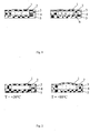
NO20064271 DE3644225A andNO20070797 - The adjustable lens illustrated in
Fig 1 comprises five elements; an actuator (for example a piezo ring) 1, mounted on a thin flexible membrane (typically glass) 2, in contact with asoft polymer 3, and preferably a stiffer substrate on theother side 5. The actuator deforms the thin flexible membrane, creating a lens shape. The deformable polymer is attached to the membrane, and the whole glass-polymer-glass structure functions as an adjustable lens. The adjustable lens design illustrated inFig 1 has the advantage of being producible using wafer processes, enabling high volume manufacturing at low unit costs. The presence of a continuous membrane made of glass or other relatively stiff, but flexible, materials in combination with a continuous or semi-continuousrigid support material 4 enables relatively easy handling in wafer scale processing, in addition to providing a support structure enabling assembly in a camera system, for example. Other adjustable optical elements may be produced employing basically the same principles, with modifications in for example the actuator geometry and the flexible membrane thickness. An example of an adjustable prism is described in patent applicationNO20070797 - Soft polymers used in the prior art techniques could have a coefficient of thermal expansion of >500ppm/K. The large difference compared to typical values for example glass or silicon (2-10ppm/K) and even stiff polymer materials (typically 50-200 ppm/K), will cause problems in a hybrid construction containing a mixture of such materials, both during manufacturing and mounting and during continuous operation. Typical operation temperatures for a mobile camera will be -25 to 55 degrees Celsius, while manufacturing temperatures could go as high as 260 degrees Celsius for brief periods of time.
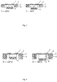
- It is possible to measure or simulate the effect of temperature increases for a lens assembly as depicted in
figure 1 . Increasing the temperature will cause a bulging of the thin glass membrane that could be several times larger than the bulging that arises from applying a voltage to the actuator. An exaggerated schematic illustration is given inFig 2 . The adjustable lenses and prisms disclosed in prior art would then have a very narrow operating temperature range, which will make the practical use of the components very limited. - In the adjustable lens design illustrated in
Fig 1 , a polymer is enclosed in a cavity. Alternative designs suggest only partially filled cavity (seen on the right hand side ofFig 1 , where 6 is an air filled void, which is also stated as reducing the effects of thermal expansion (PCT/NO2007/000332 000333 Fig 2 . - As illustrated in
figure 2 , and which also is evident for a person skilled in the art, the proposed prior art solution for compensating thermal expansion will not be sufficient as long as the lens material is a solid polymer. If the lens design comprises a liquid filled lens, as described for example in patentsJP2002239769 JP2001257932 JP2000081503 - It is therefore an aspect of the present invention to provide both passive and active methods and arrangements for compensating or minimizing the effect of thermal expansion for adjustable optical elements which are made up of a combination of materials with large differences in thermal expansion.
- It is another aspect of the present invention to provide solutions for making adjustable lenses, prisms and other optical elements that can be produced using high volume manufacturing processes, in wafer scale processes, integratable with fixed lenses and image sensors in wafer scale assembly of a complete micro camera.
- Another aspect of the present invention is to provide an adjustable lens or prism component that withstands the highly desirable lead free soldering reflow processes, which takes place at temperatures higher than 250°C. Having a micro camera that can withstand this standard process for mounting electronic components onto chip boards, is essential for the implementation of high volume/low cost manufacturing of especially consumer electronics, such as mobile cameras etc.
-
Figure 1 illustrates examples of prior art adjustable lenses comprising lens bodies made out of polymer. -
Figure 2 illustrates the effect of thermal expansion in a prior art lens assembly. -
Figure 3 illustrates an example of embodiment of the present invention. -
Figure 4a illustrates another example of embodiment of the present invention. -
Figure 4b illustrates another example of embodiment of the present invention. -
Figure 5 illustrates another example of embodiment of the present invention. - In an example of embodiment of the present invention a section of the
bottom glass element 5 is cut free from the supporting structures, as illustrated inFig 3 . The polymer in this case fills the majority of the cavity created by the thin glass membrane and the rigid walls. Thebottom element 5 may be glass, or any material that is optically transparent and stiffer than thesoft polymer 3. Other materials that could be used are for example moulded plastics and relatively stiff elastomers. - In an other example of embodiment of the present invention, illustrated in
Fig 4a , the polymer does not fill the whole cavity, but is provided in the optical light path of the lens or prism. - Another variation of this embodiment is to include an element with optical power as the bottom glass element, as illustrated in
fig. 4.b This is particularly advantageous when the adjustable lens is part of an optical objective, with one or more fixed lenses, as the bottom optical interface contributes to the total optical power of the objective, which has the function of collecting all light in focus downwards to a surface of an image sensor, for example. - According to another aspect of the present invention it is an advantage from a thermal compensation point of view to have a concave or a convex surface on the bottom glass element. Due to the thermal expansion, there will be a slight shift of the optical interfaces in the direction of the optical axis. This shift might in special lens designs cause unwanted effects, such as poor focus in the image plane or other aberration errors. A concave or convex shape - depending on the design of the whole camera objective - of the bottom glass of the thermally compensated adjustable lens will in some cases reduce such unwanted effects.
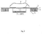
- In all the above presented embodiments, it might be advantageous to provide a small voltage to the piezo actuator as a function of temperature. This could be necessary for certain designs in order to achieve an even better compensation for thermal expansion. An example of lens profiles with (8) and without (7) such correction voltage is shown in
Fig 5 . - In order to manufacture the thermally compensated adjustable lenses in high volumes, it is evident to carry out processing on wafers, preferably using standard semi-conductor processing equipment.
- All the above mentioned embodiments will also solve the problems related to thermal expansion for other adjustable optical elements than lenses, most notably adjustable prisms, but also for other adjustable optical elements in which an actuator structure (for example a piezo actuator mounted onto a glass membrane) is attached to both a soft polymer and supporting structures for handling during manufacturing and mounting in a imaging system (camera), where large differences in thermal expansion will cause unwanted effects. Examples of such adjustable optical elements could be filters and gratings.
- The embodiments above have been described intended to work with circularly shaped or similar lenses and prisms. The same principles for thermal compensation will work also with cylindrical lenses or other lens body geometries.
- According to another aspect of the present invention, when the soft polymer is shaped with two parallel surfaces perpendicular to the optical axis, this will ensure that thermal expansion occurs parallel to the optical axis, which will not cause any distortion of the angle. In special instances, it may be desirable to have a non-parallel structure of the soft polymer, and thermal expansion will in these cases occur with a slight angular distortion from the optical axis, which can be compensated for by other optical means as known to a person skilled in the art.
Claims (7)
- An optical lens assembly comprising a soft and deformable lens body (3), a thin glass surface (2) provided with actuators (1), side walls (4) and a transparent plate (5), wherein the soft and deformable lens body (3) is confined in a cavity bounded by a first side formed by the thin glass surface (2), the side walls (4) and a second surface constituting a bottom side of the cavity formed by the transparent plate (5) wherein the thin glass surface (2) is supported by the side walls (4) and the transparent plate (5) is attached onto the lens body such that there is an opening between the side walls and the edges of the transparent plate, the transparent plate (5) being entirely cut free from said sidewalls (4).
- An optical lens assembly according to claim 1, wherein said transparent plate (5) has a surface intersecting an optical axis in the optical lens assembly, wherein the surface has a concave or convex shape.
- The optical lens assembly according to claim 1, wherein the soft and deformable lens body (2) is arranged in an optical light path of the optical lens assembly, the lens body (2) is located in the cavity with an opening around the lens body (2) and the sidewalls (4).
- The optical lens assembly according to claim 1, wherein the attached transparent plate (5) has optical power.
- The optical lens assembly according to claim 1, wherein the deformable lens body (2) comprises two opposite located parallel surfaces perpendicular to a same optical axis in the lens body (2).
- The optical lens assembly according to claim 1, wherein the deformable lens body (2) comprises at least two opposite located surfaces intersecting a same optical axis in the lens body (2) that are non- parallel.
- The optical lens assembly according to claim 1, wherein a bias voltage is applied to the actuators (1), wherein the bias voltage is proportional to temperature of the optical lens assembly.
Priority Applications (1)
| Application Number | Priority Date | Filing Date | Title |
|---|---|---|---|
| PL09794692T PL2313798T3 (en) | 2008-07-11 | 2009-07-09 | A method and arrangement for reducing thermal effects in compact adjustable optical lenses |
Applications Claiming Priority (2)
| Application Number | Priority Date | Filing Date | Title |
|---|---|---|---|
| NO20083118 | 2008-07-11 | ||
| PCT/NO2009/000255 WO2010005315A1 (en) | 2008-07-11 | 2009-07-09 | A method and arrangement for reducing thermal effects in compact adjustable optical lenses |
Publications (3)
| Publication Number | Publication Date |
|---|---|
| EP2313798A1 EP2313798A1 (en) | 2011-04-27 |
| EP2313798A4 EP2313798A4 (en) | 2012-02-08 |
| EP2313798B1 true EP2313798B1 (en) | 2017-12-27 |
Family
ID=41507258
Family Applications (1)
| Application Number | Title | Priority Date | Filing Date |
|---|---|---|---|
| EP09794692.5A Active EP2313798B1 (en) | 2008-07-11 | 2009-07-09 | A method and arrangement for reducing thermal effects in compact adjustable optical lenses |
Country Status (7)
| Country | Link |
|---|---|
| US (1) | US8310772B2 (en) |
| EP (1) | EP2313798B1 (en) |
| JP (1) | JP5580819B2 (en) |
| KR (1) | KR101372042B1 (en) |
| CN (2) | CN106324728B (en) |
| PL (1) | PL2313798T3 (en) |
| WO (1) | WO2010005315A1 (en) |
Families Citing this family (16)
| Publication number | Priority date | Publication date | Assignee | Title |
|---|---|---|---|---|
| NO326372B1 (en) * | 2006-09-21 | 2008-11-17 | Polight As | Polymer Lens |
| CN101600976B (en) | 2006-10-11 | 2011-11-09 | 珀莱特公司 | Design of compact adjustable lens |
| WO2008044938A1 (en) | 2006-10-11 | 2008-04-17 | Ignis Display As | Method for manufacturing adjustable lens |
| KR101452011B1 (en) | 2007-02-12 | 2014-10-21 | 포라이트 에이에스 | Lens assembly |
| KR101912092B1 (en) | 2010-10-05 | 2018-10-26 | 삼성전자 주식회사 | Fluidic lens |
| KR101912093B1 (en) | 2010-10-29 | 2018-10-26 | 삼성전자 주식회사 | Optical apparatus |
| EP2781939B1 (en) | 2013-03-18 | 2015-11-04 | poLight AS | Deformable polymeric lens |
| DE102013110750B3 (en) * | 2013-09-27 | 2014-11-13 | Jenoptik Optical Systems Gmbh | Optical assembly with a socket with thermally dependent force compensation |
| DE102014114253A1 (en) | 2013-09-30 | 2015-04-02 | Jenoptik Optical Systems Gmbh | Method for compensating aberrations caused by thermal lens effects in an optic |
| WO2016202392A1 (en) * | 2015-06-17 | 2016-12-22 | Optotune Ag | Temperature drift compensation for liquid lenses |
| US10602070B2 (en) | 2016-01-27 | 2020-03-24 | Raytheon Company | Variable magnification active imaging system |
| US10382701B2 (en) | 2016-01-27 | 2019-08-13 | Raytheon Company | Active imaging systems and method |
| US11346984B2 (en) * | 2017-02-09 | 2022-05-31 | Corning Incorporated | Liquid lenses |
| WO2019002524A1 (en) * | 2017-06-30 | 2019-01-03 | Polight As | Lens assembly for optical image stabilization and focus adjustment |
| CN107436496A (en) * | 2017-08-16 | 2017-12-05 | 邵洁茹 | Temperature compensation system |
| EP3803490A1 (en) * | 2018-05-24 | 2021-04-14 | poLight ASA | Optical element with stress distributing supporting structure |
Citations (1)
| Publication number | Priority date | Publication date | Assignee | Title |
|---|---|---|---|---|
| WO2008035983A1 (en) * | 2006-09-21 | 2008-03-27 | Sinvent As | Polymer lens |
Family Cites Families (43)
| Publication number | Priority date | Publication date | Assignee | Title |
|---|---|---|---|---|
| US4795248A (en) * | 1984-08-31 | 1989-01-03 | Olympus Optical Company Ltd. | Liquid crystal eyeglass |
| JPS62148903A (en) | 1985-12-24 | 1987-07-02 | Canon Inc | Variable focus optical element |
| JPS62151824A (en) | 1985-12-26 | 1987-07-06 | Matsushita Electric Ind Co Ltd | Vari-focal lens |
| JPH0740090B2 (en) * | 1986-12-26 | 1995-05-01 | キヤノン株式会社 | Variable focus optics |
| JPS6462609A (en) | 1987-09-02 | 1989-03-09 | Ryohei Ishida | Ultraviolet-ray microscope unit |
| JPH01140118A (en) | 1987-11-27 | 1989-06-01 | Mitsubishi Heavy Ind Ltd | Focal length variable lens |
| JPH02178602A (en) | 1988-12-29 | 1990-07-11 | Seikosha Co Ltd | Vari-focal lens |
| US5886332A (en) | 1994-04-19 | 1999-03-23 | Geo Labs, Inc. | Beam shaping system with surface treated lens and methods for making same |
| US5774274A (en) | 1995-05-12 | 1998-06-30 | Schachar; Ronald A. | Variable focus lens by small changes of the equatorial lens diameter |
| JPH11133210A (en) * | 1997-10-30 | 1999-05-21 | Denso Corp | Variable focus lens |
| JPH11174522A (en) * | 1997-12-15 | 1999-07-02 | Asahi Optical Co Ltd | Iris device |
| JP4078575B2 (en) * | 1998-06-26 | 2008-04-23 | 株式会社デンソー | Variable focus lens device |
| JP2000249813A (en) | 1999-03-02 | 2000-09-14 | Japan Science & Technology Corp | Variable focus lens |
| JP4532651B2 (en) * | 2000-03-03 | 2010-08-25 | キヤノン株式会社 | Variable focus lens, optical system and photographing apparatus |
| JP2001257932A (en) | 2000-03-09 | 2001-09-21 | Denso Corp | Image pickup device |
| JP2002243918A (en) | 2001-02-14 | 2002-08-28 | Olympus Optical Co Ltd | Variable focus lens, optical characteristic variable optical element, and optical device |
| DE10046379A1 (en) | 2000-09-20 | 2002-03-28 | Zeiss Carl | System for the targeted deformation of optical elements |
| US7646544B2 (en) * | 2005-05-14 | 2010-01-12 | Batchko Robert G | Fluidic optical devices |
| US7672059B2 (en) | 2000-10-20 | 2010-03-02 | Holochip Corporation | Fluidic lens with electrostatic actuation |
| JP2002239769A (en) | 2001-02-21 | 2002-08-28 | Denso Corp | Device and method for laser beam machining |
| US6666559B2 (en) | 2001-04-17 | 2003-12-23 | Olympus Optical Co., Ltd. | Variable-profile optical device including variable-profile mirror and optical element including variable-profile optical element |
| JP2003029150A (en) | 2001-07-13 | 2003-01-29 | Olympus Optical Co Ltd | Optical system and optical device including optical characteristic variable optical element |
| DE60334023D1 (en) | 2002-10-25 | 2010-10-14 | Koninkl Philips Electronics Nv | ZOOM LENS |
| US7209280B2 (en) | 2002-12-30 | 2007-04-24 | Koninklijke Philips Electronics N.V. | Optical device comprising a polymer actuator |
| EP1599748A4 (en) | 2003-03-06 | 2007-10-24 | John H Shadduck | Adaptive optic lens and method of making |
| CN100439968C (en) * | 2003-05-09 | 2008-12-03 | 皇家飞利浦电子股份有限公司 | Electrowetting cells |
| KR100513310B1 (en) | 2003-12-19 | 2005-09-07 | 삼성전자주식회사 | Semiconductor device having two different operation modes employing an asymmetrical buried insulating layer and method of fabricating the same |
| DE102004011026A1 (en) | 2004-03-04 | 2005-09-29 | Siemens Ag | Adaptive optical element with a polymer actuator |
| CN2706779Y (en) | 2004-03-30 | 2005-06-29 | 鸿富锦精密工业(深圳)有限公司 | Vari-focal lens module |
| US7359124B1 (en) * | 2004-04-30 | 2008-04-15 | Louisiana Tech University Research Foundation As A Division Of The Louisiana Tech University Foundation | Wide-angle variable focal length lens system |
| CN100529945C (en) | 2004-12-17 | 2009-08-19 | 鸿富锦精密工业(深圳)有限公司 | Automatic focusing device |
| CN100555055C (en) * | 2004-12-24 | 2009-10-28 | 鸿富锦精密工业(深圳)有限公司 | Automatic focusing mechanism |
| US7436484B2 (en) | 2004-12-28 | 2008-10-14 | Asml Netherlands B.V. | Lithographic apparatus and device manufacturing method |
| FR2887638B1 (en) * | 2005-06-23 | 2007-08-31 | Varioptic Sa | VARIABLE FOCAL LENS WITH REDUCED INTERNAL PRESSURE VARIATION |
| JP5069232B2 (en) | 2005-07-25 | 2012-11-07 | カール・ツァイス・エスエムティー・ゲーエムベーハー | Projection objective lens of microlithography projection exposure apparatus |
| KR100723241B1 (en) * | 2005-12-29 | 2007-05-29 | 삼성전기주식회사 | Adjustable-focus lens having a plurality of protrusions at one end of fluid chamber |
| CN101034201A (en) | 2006-03-10 | 2007-09-12 | 鸿富锦精密工业(深圳)有限公司 | Zoom lens module group and lens module group using same |
| WO2008044938A1 (en) * | 2006-10-11 | 2008-04-17 | Ignis Display As | Method for manufacturing adjustable lens |
| CN101600976B (en) | 2006-10-11 | 2011-11-09 | 珀莱特公司 | Design of compact adjustable lens |
| US7813047B2 (en) | 2006-12-15 | 2010-10-12 | Hand Held Products, Inc. | Apparatus and method comprising deformable lens element |
| KR101452011B1 (en) | 2007-02-12 | 2014-10-21 | 포라이트 에이에스 | Lens assembly |
| WO2008100153A1 (en) | 2007-02-12 | 2008-08-21 | Polight As | A device for providing stabilized images in a hand held camera |
| US20080277480A1 (en) | 2007-05-10 | 2008-11-13 | Serge Thuries | Temperature compensated auto focus control for a microfluidic lens, such as auto focus control for a microfluidic lens of a bar code scanner |
-
2009
- 2009-07-09 JP JP2011517372A patent/JP5580819B2/en active Active
- 2009-07-09 CN CN201610806662.7A patent/CN106324728B/en active Active
- 2009-07-09 WO PCT/NO2009/000255 patent/WO2010005315A1/en active Application Filing
- 2009-07-09 US US13/002,706 patent/US8310772B2/en active Active
- 2009-07-09 PL PL09794692T patent/PL2313798T3/en unknown
- 2009-07-09 EP EP09794692.5A patent/EP2313798B1/en active Active
- 2009-07-09 CN CN2009801271510A patent/CN102089681A/en active Pending
- 2009-07-09 KR KR1020117002972A patent/KR101372042B1/en active IP Right Grant
Patent Citations (1)
| Publication number | Priority date | Publication date | Assignee | Title |
|---|---|---|---|---|
| WO2008035983A1 (en) * | 2006-09-21 | 2008-03-27 | Sinvent As | Polymer lens |
Also Published As
| Publication number | Publication date |
|---|---|
| JP2011527764A (en) | 2011-11-04 |
| CN106324728B (en) | 2018-09-04 |
| CN102089681A (en) | 2011-06-08 |
| JP5580819B2 (en) | 2014-08-27 |
| US20110164330A1 (en) | 2011-07-07 |
| KR20110042302A (en) | 2011-04-26 |
| US8310772B2 (en) | 2012-11-13 |
| PL2313798T3 (en) | 2018-08-31 |
| KR101372042B1 (en) | 2014-03-07 |
| EP2313798A4 (en) | 2012-02-08 |
| WO2010005315A1 (en) | 2010-01-14 |
| EP2313798A1 (en) | 2011-04-27 |
| CN106324728A (en) | 2017-01-11 |
Similar Documents
| Publication | Publication Date | Title |
|---|---|---|
| EP2313798B1 (en) | A method and arrangement for reducing thermal effects in compact adjustable optical lenses | |
| EP2074444B1 (en) | Design of compact adjustable lens | |
| JP5362587B2 (en) | Flexible lens assembly with variable focal length | |
| KR101496157B1 (en) | Polymer lens | |
| EP2074445B1 (en) | Method for manufacturing adjustable lens | |
| EP2447742A1 (en) | Optical apparatus | |
| US9869802B2 (en) | Optical device with focal length variation | |
| JP2015180963A (en) | optical laminate and method of manufacturing the same | |
| EP2439563B1 (en) | Fluidic lens | |
| CN110226117B (en) | Liquid lens | |
| TWI824011B (en) | A variable volume liquid lens and a camera system | |
| Draheim et al. | 10 Piezoelectrically Actuated Tunable Microlenses | |
| JP2015119318A (en) | Imaging apparatus, and manufacturing method of imaging apparatus | |
| Pätz et al. | 15 Adaptive Scanning Micro-eye |
Legal Events
| Date | Code | Title | Description |
|---|---|---|---|
| PUAI | Public reference made under article 153(3) epc to a published international application that has entered the european phase |
Free format text: ORIGINAL CODE: 0009012 |
|
| 17P | Request for examination filed |
Effective date: 20110211 |
|
| AK | Designated contracting states |
Kind code of ref document: A1 Designated state(s): AT BE BG CH CY CZ DE DK EE ES FI FR GB GR HR HU IE IS IT LI LT LU LV MC MK MT NL NO PL PT RO SE SI SK SM TR |
|
| AX | Request for extension of the european patent |
Extension state: AL BA RS |
|
| DAX | Request for extension of the european patent (deleted) | ||
| A4 | Supplementary search report drawn up and despatched |
Effective date: 20120105 |
|
| RIC1 | Information provided on ipc code assigned before grant |
Ipc: G02B 3/12 20060101ALI20111230BHEP Ipc: G02B 7/02 20060101ALI20111230BHEP Ipc: G02B 26/02 20060101ALI20111230BHEP Ipc: G02B 27/40 20060101ALI20111230BHEP Ipc: G02B 3/14 20060101AFI20111230BHEP |
|
| 17Q | First examination report despatched |
Effective date: 20151209 |
|
| GRAP | Despatch of communication of intention to grant a patent |
Free format text: ORIGINAL CODE: EPIDOSNIGR1 |
|
| INTG | Intention to grant announced |
Effective date: 20170110 |
|
| GRAJ | Information related to disapproval of communication of intention to grant by the applicant or resumption of examination proceedings by the epo deleted |
Free format text: ORIGINAL CODE: EPIDOSDIGR1 |
|
| INTC | Intention to grant announced (deleted) | ||
| GRAS | Grant fee paid |
Free format text: ORIGINAL CODE: EPIDOSNIGR3 |
|
| GRAP | Despatch of communication of intention to grant a patent |
Free format text: ORIGINAL CODE: EPIDOSNIGR1 |
|
| INTG | Intention to grant announced |
Effective date: 20170712 |
|
| GRAA | (expected) grant |
Free format text: ORIGINAL CODE: 0009210 |
|
| AK | Designated contracting states |
Kind code of ref document: B1 Designated state(s): AT BE BG CH CY CZ DE DK EE ES FI FR GB GR HR HU IE IS IT LI LT LU LV MC MK MT NL NO PL PT RO SE SI SK SM TR |
|
| REG | Reference to a national code |
Ref country code: GB Ref legal event code: FG4D |
|
| REG | Reference to a national code |
Ref country code: CH Ref legal event code: EP |
|
| REG | Reference to a national code |
Ref country code: AT Ref legal event code: REF Ref document number: 958780 Country of ref document: AT Kind code of ref document: T Effective date: 20180115 |
|
| REG | Reference to a national code |
Ref country code: IE Ref legal event code: FG4D |
|
| REG | Reference to a national code |
Ref country code: DE Ref legal event code: R096 Ref document number: 602009050135 Country of ref document: DE |
|
| REG | Reference to a national code |
Ref country code: NL Ref legal event code: FP |
|
| PG25 | Lapsed in a contracting state [announced via postgrant information from national office to epo] |
Ref country code: LT Free format text: LAPSE BECAUSE OF FAILURE TO SUBMIT A TRANSLATION OF THE DESCRIPTION OR TO PAY THE FEE WITHIN THE PRESCRIBED TIME-LIMIT Effective date: 20171227 Ref country code: NO Free format text: LAPSE BECAUSE OF FAILURE TO SUBMIT A TRANSLATION OF THE DESCRIPTION OR TO PAY THE FEE WITHIN THE PRESCRIBED TIME-LIMIT Effective date: 20180327 |
|
| REG | Reference to a national code |
Ref country code: LT Ref legal event code: MG4D |
|
| REG | Reference to a national code |
Ref country code: AT Ref legal event code: MK05 Ref document number: 958780 Country of ref document: AT Kind code of ref document: T Effective date: 20171227 |
|
| PG25 | Lapsed in a contracting state [announced via postgrant information from national office to epo] |
Ref country code: LV Free format text: LAPSE BECAUSE OF FAILURE TO SUBMIT A TRANSLATION OF THE DESCRIPTION OR TO PAY THE FEE WITHIN THE PRESCRIBED TIME-LIMIT Effective date: 20171227 Ref country code: GR Free format text: LAPSE BECAUSE OF FAILURE TO SUBMIT A TRANSLATION OF THE DESCRIPTION OR TO PAY THE FEE WITHIN THE PRESCRIBED TIME-LIMIT Effective date: 20180328 Ref country code: HR Free format text: LAPSE BECAUSE OF FAILURE TO SUBMIT A TRANSLATION OF THE DESCRIPTION OR TO PAY THE FEE WITHIN THE PRESCRIBED TIME-LIMIT Effective date: 20171227 Ref country code: BG Free format text: LAPSE BECAUSE OF FAILURE TO SUBMIT A TRANSLATION OF THE DESCRIPTION OR TO PAY THE FEE WITHIN THE PRESCRIBED TIME-LIMIT Effective date: 20180327 |
|
| REG | Reference to a national code |
Ref country code: FR Ref legal event code: PLFP Year of fee payment: 10 |
|
| PG25 | Lapsed in a contracting state [announced via postgrant information from national office to epo] |
Ref country code: EE Free format text: LAPSE BECAUSE OF FAILURE TO SUBMIT A TRANSLATION OF THE DESCRIPTION OR TO PAY THE FEE WITHIN THE PRESCRIBED TIME-LIMIT Effective date: 20171227 Ref country code: CZ Free format text: LAPSE BECAUSE OF FAILURE TO SUBMIT A TRANSLATION OF THE DESCRIPTION OR TO PAY THE FEE WITHIN THE PRESCRIBED TIME-LIMIT Effective date: 20171227 Ref country code: SK Free format text: LAPSE BECAUSE OF FAILURE TO SUBMIT A TRANSLATION OF THE DESCRIPTION OR TO PAY THE FEE WITHIN THE PRESCRIBED TIME-LIMIT Effective date: 20171227 Ref country code: ES Free format text: LAPSE BECAUSE OF FAILURE TO SUBMIT A TRANSLATION OF THE DESCRIPTION OR TO PAY THE FEE WITHIN THE PRESCRIBED TIME-LIMIT Effective date: 20171227 Ref country code: CY Free format text: LAPSE BECAUSE OF FAILURE TO SUBMIT A TRANSLATION OF THE DESCRIPTION OR TO PAY THE FEE WITHIN THE PRESCRIBED TIME-LIMIT Effective date: 20171227 |
|
| PG25 | Lapsed in a contracting state [announced via postgrant information from national office to epo] |
Ref country code: SM Free format text: LAPSE BECAUSE OF FAILURE TO SUBMIT A TRANSLATION OF THE DESCRIPTION OR TO PAY THE FEE WITHIN THE PRESCRIBED TIME-LIMIT Effective date: 20171227 Ref country code: RO Free format text: LAPSE BECAUSE OF FAILURE TO SUBMIT A TRANSLATION OF THE DESCRIPTION OR TO PAY THE FEE WITHIN THE PRESCRIBED TIME-LIMIT Effective date: 20171227 Ref country code: IS Free format text: LAPSE BECAUSE OF FAILURE TO SUBMIT A TRANSLATION OF THE DESCRIPTION OR TO PAY THE FEE WITHIN THE PRESCRIBED TIME-LIMIT Effective date: 20180427 Ref country code: AT Free format text: LAPSE BECAUSE OF FAILURE TO SUBMIT A TRANSLATION OF THE DESCRIPTION OR TO PAY THE FEE WITHIN THE PRESCRIBED TIME-LIMIT Effective date: 20171227 |
|
| REG | Reference to a national code |
Ref country code: DE Ref legal event code: R097 Ref document number: 602009050135 Country of ref document: DE |
|
| PLBE | No opposition filed within time limit |
Free format text: ORIGINAL CODE: 0009261 |
|
| STAA | Information on the status of an ep patent application or granted ep patent |
Free format text: STATUS: NO OPPOSITION FILED WITHIN TIME LIMIT |
|
| PG25 | Lapsed in a contracting state [announced via postgrant information from national office to epo] |
Ref country code: DK Free format text: LAPSE BECAUSE OF FAILURE TO SUBMIT A TRANSLATION OF THE DESCRIPTION OR TO PAY THE FEE WITHIN THE PRESCRIBED TIME-LIMIT Effective date: 20171227 |
|
| 26N | No opposition filed |
Effective date: 20180928 |
|
| PG25 | Lapsed in a contracting state [announced via postgrant information from national office to epo] |
Ref country code: SI Free format text: LAPSE BECAUSE OF FAILURE TO SUBMIT A TRANSLATION OF THE DESCRIPTION OR TO PAY THE FEE WITHIN THE PRESCRIBED TIME-LIMIT Effective date: 20171227 |
|
| PG25 | Lapsed in a contracting state [announced via postgrant information from national office to epo] |
Ref country code: MC Free format text: LAPSE BECAUSE OF FAILURE TO SUBMIT A TRANSLATION OF THE DESCRIPTION OR TO PAY THE FEE WITHIN THE PRESCRIBED TIME-LIMIT Effective date: 20171227 Ref country code: LU Free format text: LAPSE BECAUSE OF NON-PAYMENT OF DUE FEES Effective date: 20180709 |
|
| REG | Reference to a national code |
Ref country code: BE Ref legal event code: MM Effective date: 20180731 |
|
| REG | Reference to a national code |
Ref country code: IE Ref legal event code: MM4A |
|
| PG25 | Lapsed in a contracting state [announced via postgrant information from national office to epo] |
Ref country code: IE Free format text: LAPSE BECAUSE OF NON-PAYMENT OF DUE FEES Effective date: 20180709 |
|
| PG25 | Lapsed in a contracting state [announced via postgrant information from national office to epo] |
Ref country code: BE Free format text: LAPSE BECAUSE OF NON-PAYMENT OF DUE FEES Effective date: 20180731 |
|
| PG25 | Lapsed in a contracting state [announced via postgrant information from national office to epo] |
Ref country code: MT Free format text: LAPSE BECAUSE OF NON-PAYMENT OF DUE FEES Effective date: 20180709 |
|
| PG25 | Lapsed in a contracting state [announced via postgrant information from national office to epo] |
Ref country code: PT Free format text: LAPSE BECAUSE OF FAILURE TO SUBMIT A TRANSLATION OF THE DESCRIPTION OR TO PAY THE FEE WITHIN THE PRESCRIBED TIME-LIMIT Effective date: 20171227 Ref country code: HU Free format text: LAPSE BECAUSE OF FAILURE TO SUBMIT A TRANSLATION OF THE DESCRIPTION OR TO PAY THE FEE WITHIN THE PRESCRIBED TIME-LIMIT; INVALID AB INITIO Effective date: 20090709 |
|
| PG25 | Lapsed in a contracting state [announced via postgrant information from national office to epo] |
Ref country code: SE Free format text: LAPSE BECAUSE OF FAILURE TO SUBMIT A TRANSLATION OF THE DESCRIPTION OR TO PAY THE FEE WITHIN THE PRESCRIBED TIME-LIMIT Effective date: 20171227 Ref country code: MK Free format text: LAPSE BECAUSE OF NON-PAYMENT OF DUE FEES Effective date: 20171227 |
|
| P01 | Opt-out of the competence of the unified patent court (upc) registered |
Effective date: 20230510 |
|
| PGFP | Annual fee paid to national office [announced via postgrant information from national office to epo] |
Ref country code: NL Payment date: 20230719 Year of fee payment: 15 |
|
| PGFP | Annual fee paid to national office [announced via postgrant information from national office to epo] |
Ref country code: TR Payment date: 20230706 Year of fee payment: 15 Ref country code: IT Payment date: 20230724 Year of fee payment: 15 Ref country code: GB Payment date: 20230720 Year of fee payment: 15 Ref country code: FI Payment date: 20230719 Year of fee payment: 15 Ref country code: CH Payment date: 20230801 Year of fee payment: 15 |
|
| PGFP | Annual fee paid to national office [announced via postgrant information from national office to epo] |
Ref country code: PL Payment date: 20230703 Year of fee payment: 15 Ref country code: FR Payment date: 20230725 Year of fee payment: 15 Ref country code: DE Payment date: 20230719 Year of fee payment: 15 |