EP2313752B1 - Capteur d'aérosol - Google Patents
Capteur d'aérosol Download PDFInfo
- Publication number
- EP2313752B1 EP2313752B1 EP09771838.1A EP09771838A EP2313752B1 EP 2313752 B1 EP2313752 B1 EP 2313752B1 EP 09771838 A EP09771838 A EP 09771838A EP 2313752 B1 EP2313752 B1 EP 2313752B1
- Authority
- EP
- European Patent Office
- Prior art keywords
- aerosol
- cooling effect
- measuring
- gas stream
- flow rate
- Prior art date
- Legal status (The legal status is an assumption and is not a legal conclusion. Google has not performed a legal analysis and makes no representation as to the accuracy of the status listed.)
- Active
Links
- 239000000443 aerosol Substances 0.000 title claims description 158
- 239000007789 gas Substances 0.000 claims description 83
- 238000001816 cooling Methods 0.000 claims description 76
- 230000000694 effects Effects 0.000 claims description 73
- 238000000034 method Methods 0.000 claims description 37
- 230000001954 sterilising effect Effects 0.000 claims description 20
- MHAJPDPJQMAIIY-UHFFFAOYSA-N Hydrogen peroxide Chemical compound OO MHAJPDPJQMAIIY-UHFFFAOYSA-N 0.000 claims description 13
- 238000010438 heat treatment Methods 0.000 claims description 5
- 238000009834 vaporization Methods 0.000 claims description 2
- 238000004659 sterilization and disinfection Methods 0.000 description 29
- 239000007788 liquid Substances 0.000 description 13
- 238000005259 measurement Methods 0.000 description 10
- 230000037361 pathway Effects 0.000 description 9
- 239000003595 mist Substances 0.000 description 8
- 239000002245 particle Substances 0.000 description 8
- 230000008021 deposition Effects 0.000 description 6
- 238000012544 monitoring process Methods 0.000 description 6
- 239000003795 chemical substances by application Substances 0.000 description 5
- 238000001704 evaporation Methods 0.000 description 5
- BASFCYQUMIYNBI-UHFFFAOYSA-N platinum Chemical compound [Pt] BASFCYQUMIYNBI-UHFFFAOYSA-N 0.000 description 5
- 238000009833 condensation Methods 0.000 description 4
- 230000005494 condensation Effects 0.000 description 4
- 230000008020 evaporation Effects 0.000 description 4
- 230000008569 process Effects 0.000 description 4
- 238000011088 calibration curve Methods 0.000 description 3
- 239000012159 carrier gas Substances 0.000 description 3
- 230000001276 controlling effect Effects 0.000 description 3
- 230000003287 optical effect Effects 0.000 description 3
- XLYOFNOQVPJJNP-UHFFFAOYSA-N water Substances O XLYOFNOQVPJJNP-UHFFFAOYSA-N 0.000 description 3
- 230000003197 catalytic effect Effects 0.000 description 2
- 230000008859 change Effects 0.000 description 2
- 230000002596 correlated effect Effects 0.000 description 2
- 239000012530 fluid Substances 0.000 description 2
- 239000011521 glass Substances 0.000 description 2
- 239000000463 material Substances 0.000 description 2
- 229910052751 metal Inorganic materials 0.000 description 2
- 239000002184 metal Substances 0.000 description 2
- 244000005700 microbiome Species 0.000 description 2
- 150000002978 peroxides Chemical class 0.000 description 2
- 230000001105 regulatory effect Effects 0.000 description 2
- 230000004044 response Effects 0.000 description 2
- 239000000243 solution Substances 0.000 description 2
- 239000003206 sterilizing agent Substances 0.000 description 2
- 239000002699 waste material Substances 0.000 description 2
- 241000894006 Bacteria Species 0.000 description 1
- 241000233866 Fungi Species 0.000 description 1
- 240000004922 Vigna radiata Species 0.000 description 1
- 238000013459 approach Methods 0.000 description 1
- 239000007864 aqueous solution Substances 0.000 description 1
- 238000000149 argon plasma sintering Methods 0.000 description 1
- 230000008901 benefit Effects 0.000 description 1
- 230000005540 biological transmission Effects 0.000 description 1
- 238000009529 body temperature measurement Methods 0.000 description 1
- 239000000919 ceramic Substances 0.000 description 1
- 238000004891 communication Methods 0.000 description 1
- 230000001066 destructive effect Effects 0.000 description 1
- 238000010586 diagram Methods 0.000 description 1
- 238000005516 engineering process Methods 0.000 description 1
- 238000002474 experimental method Methods 0.000 description 1
- 230000017525 heat dissipation Effects 0.000 description 1
- 239000008241 heterogeneous mixture Substances 0.000 description 1
- 239000011159 matrix material Substances 0.000 description 1
- 150000002739 metals Chemical class 0.000 description 1
- 238000013021 overheating Methods 0.000 description 1
- 238000004806 packaging method and process Methods 0.000 description 1
- 238000002161 passivation Methods 0.000 description 1
- 230000005855 radiation Effects 0.000 description 1
- 230000009467 reduction Effects 0.000 description 1
- 230000035945 sensitivity Effects 0.000 description 1
- 239000002904 solvent Substances 0.000 description 1
- 239000000126 substance Substances 0.000 description 1
- 239000000758 substrate Substances 0.000 description 1
- 238000012360 testing method Methods 0.000 description 1
Images


Classifications
-
- A—HUMAN NECESSITIES
- A61—MEDICAL OR VETERINARY SCIENCE; HYGIENE
- A61L—METHODS OR APPARATUS FOR STERILISING MATERIALS OR OBJECTS IN GENERAL; DISINFECTION, STERILISATION OR DEODORISATION OF AIR; CHEMICAL ASPECTS OF BANDAGES, DRESSINGS, ABSORBENT PADS OR SURGICAL ARTICLES; MATERIALS FOR BANDAGES, DRESSINGS, ABSORBENT PADS OR SURGICAL ARTICLES
- A61L2/00—Methods or apparatus for disinfecting or sterilising materials or objects other than foodstuffs or contact lenses; Accessories therefor
- A61L2/26—Accessories or devices or components used for biocidal treatment
-
- G—PHYSICS
- G01—MEASURING; TESTING
- G01K—MEASURING TEMPERATURE; MEASURING QUANTITY OF HEAT; THERMALLY-SENSITIVE ELEMENTS NOT OTHERWISE PROVIDED FOR
- G01K13/00—Thermometers specially adapted for specific purposes
- G01K13/02—Thermometers specially adapted for specific purposes for measuring temperature of moving fluids or granular materials capable of flow
-
- A—HUMAN NECESSITIES
- A61—MEDICAL OR VETERINARY SCIENCE; HYGIENE
- A61L—METHODS OR APPARATUS FOR STERILISING MATERIALS OR OBJECTS IN GENERAL; DISINFECTION, STERILISATION OR DEODORISATION OF AIR; CHEMICAL ASPECTS OF BANDAGES, DRESSINGS, ABSORBENT PADS OR SURGICAL ARTICLES; MATERIALS FOR BANDAGES, DRESSINGS, ABSORBENT PADS OR SURGICAL ARTICLES
- A61L2/00—Methods or apparatus for disinfecting or sterilising materials or objects other than foodstuffs or contact lenses; Accessories therefor
- A61L2/16—Methods or apparatus for disinfecting or sterilising materials or objects other than foodstuffs or contact lenses; Accessories therefor using chemical substances
- A61L2/20—Gaseous substances, e.g. vapours
-
- A—HUMAN NECESSITIES
- A61—MEDICAL OR VETERINARY SCIENCE; HYGIENE
- A61L—METHODS OR APPARATUS FOR STERILISING MATERIALS OR OBJECTS IN GENERAL; DISINFECTION, STERILISATION OR DEODORISATION OF AIR; CHEMICAL ASPECTS OF BANDAGES, DRESSINGS, ABSORBENT PADS OR SURGICAL ARTICLES; MATERIALS FOR BANDAGES, DRESSINGS, ABSORBENT PADS OR SURGICAL ARTICLES
- A61L2/00—Methods or apparatus for disinfecting or sterilising materials or objects other than foodstuffs or contact lenses; Accessories therefor
- A61L2/16—Methods or apparatus for disinfecting or sterilising materials or objects other than foodstuffs or contact lenses; Accessories therefor using chemical substances
- A61L2/22—Phase substances, e.g. smokes, aerosols or sprayed or atomised substances
-
- A—HUMAN NECESSITIES
- A61—MEDICAL OR VETERINARY SCIENCE; HYGIENE
- A61L—METHODS OR APPARATUS FOR STERILISING MATERIALS OR OBJECTS IN GENERAL; DISINFECTION, STERILISATION OR DEODORISATION OF AIR; CHEMICAL ASPECTS OF BANDAGES, DRESSINGS, ABSORBENT PADS OR SURGICAL ARTICLES; MATERIALS FOR BANDAGES, DRESSINGS, ABSORBENT PADS OR SURGICAL ARTICLES
- A61L2/00—Methods or apparatus for disinfecting or sterilising materials or objects other than foodstuffs or contact lenses; Accessories therefor
- A61L2/26—Accessories or devices or components used for biocidal treatment
- A61L2/28—Devices for testing the effectiveness or completeness of sterilisation, e.g. indicators which change colour
-
- G—PHYSICS
- G01—MEASURING; TESTING
- G01K—MEASURING TEMPERATURE; MEASURING QUANTITY OF HEAT; THERMALLY-SENSITIVE ELEMENTS NOT OTHERWISE PROVIDED FOR
- G01K7/00—Measuring temperature based on the use of electric or magnetic elements directly sensitive to heat ; Power supply therefor, e.g. using thermoelectric elements
- G01K7/16—Measuring temperature based on the use of electric or magnetic elements directly sensitive to heat ; Power supply therefor, e.g. using thermoelectric elements using resistive elements
-
- G—PHYSICS
- G01—MEASURING; TESTING
- G01N—INVESTIGATING OR ANALYSING MATERIALS BY DETERMINING THEIR CHEMICAL OR PHYSICAL PROPERTIES
- G01N9/00—Investigating density or specific gravity of materials; Analysing materials by determining density or specific gravity
-
- A—HUMAN NECESSITIES
- A61—MEDICAL OR VETERINARY SCIENCE; HYGIENE
- A61L—METHODS OR APPARATUS FOR STERILISING MATERIALS OR OBJECTS IN GENERAL; DISINFECTION, STERILISATION OR DEODORISATION OF AIR; CHEMICAL ASPECTS OF BANDAGES, DRESSINGS, ABSORBENT PADS OR SURGICAL ARTICLES; MATERIALS FOR BANDAGES, DRESSINGS, ABSORBENT PADS OR SURGICAL ARTICLES
- A61L2/00—Methods or apparatus for disinfecting or sterilising materials or objects other than foodstuffs or contact lenses; Accessories therefor
- A61L2/16—Methods or apparatus for disinfecting or sterilising materials or objects other than foodstuffs or contact lenses; Accessories therefor using chemical substances
- A61L2/18—Liquid substances or solutions comprising solids or dissolved gases
- A61L2/186—Peroxide solutions
-
- A—HUMAN NECESSITIES
- A61—MEDICAL OR VETERINARY SCIENCE; HYGIENE
- A61L—METHODS OR APPARATUS FOR STERILISING MATERIALS OR OBJECTS IN GENERAL; DISINFECTION, STERILISATION OR DEODORISATION OF AIR; CHEMICAL ASPECTS OF BANDAGES, DRESSINGS, ABSORBENT PADS OR SURGICAL ARTICLES; MATERIALS FOR BANDAGES, DRESSINGS, ABSORBENT PADS OR SURGICAL ARTICLES
- A61L2202/00—Aspects relating to methods or apparatus for disinfecting or sterilising materials or objects
- A61L2202/10—Apparatus features
- A61L2202/14—Means for controlling sterilisation processes, data processing, presentation and storage means, e.g. sensors, controllers, programs
-
- Y—GENERAL TAGGING OF NEW TECHNOLOGICAL DEVELOPMENTS; GENERAL TAGGING OF CROSS-SECTIONAL TECHNOLOGIES SPANNING OVER SEVERAL SECTIONS OF THE IPC; TECHNICAL SUBJECTS COVERED BY FORMER USPC CROSS-REFERENCE ART COLLECTIONS [XRACs] AND DIGESTS
- Y10—TECHNICAL SUBJECTS COVERED BY FORMER USPC
- Y10T—TECHNICAL SUBJECTS COVERED BY FORMER US CLASSIFICATION
- Y10T436/00—Chemistry: analytical and immunological testing
- Y10T436/20—Oxygen containing
- Y10T436/206664—Ozone or peroxide
Definitions
- This invention relates to a method and apparatus for determining the density of an aerosol in a gas stream, and the use thereof for quantifying the amount of aerosol delivered to a sterilizing chamber.
- US 6318151 B1 relates to a system for monitoring levels of a sterilant during a sterilization process.
- US 2003/0039299 A1 discloses a gas concentration sensor, while WO 03/106985 A1 describes a sensor for detecting a flammable vapour in air and other gases.
- Sterilizers are used in medical, food and packaging industries to prevent the transmission of agents such as spores, fungi and bacteria.
- a typical sterilizer creates a set of physical conditions in a sterilization chamber that can effectively kill nearly all of these transmissible agents.
- One way of determining whether there has been sufficient exposure to the sterilant is to place test strips bearing a known micro-organism load in the sterilization chamber and to count the number of surviving micro organisms at the end of the sterilization process. That is time consuming, labour intensive, and impractical.
- parametric monitoring can be employed in which measurements or controls are used to ensure that proper sterilization conditions are attained.
- Regulatory requirements for medical devices dictate that sterilizers have systems to verify the completion of a successful sterilization cycle. Time and temperature are two key parameters that need to be monitored for thermal sterilizers (autoclaves), and both of these are easily monitored with current technologies.
- regulatory requirements specify that the concentration or dosage of the sterilization chemistry delivered to the sterilization chamber must also be monitored. Once all the values for the necessary parameters are met, then it is possible to certify the articles as sterile and release them for use.
- Sterilization processes which use an aerosol of microdroplets of a liquid sterilant in a gas stream (usually air) are known to be highly efficacious. These processes use, for example, an aerosol of droplets of hydrogen peroxide solution dispersed in an air stream which are kept in contact with an article to be sterilized for a predetermined time. These pose problems not only with the corrosive nature of the materials, but also the fact that a heterogeneous mixture (droplets in a gas) needs to be measured.
- concentration is used to refer to the amount or volume of active sterilising agent (such as hydrogen peroxide) relative to the amount or volume of inert carrier fluid (usually water) present.
- active sterilising agent such as hydrogen peroxide
- inert carrier fluid usually water
- concentration can be used in relation to a bulk liquid, to an individual aerosol particle, or to a collective group of aerosol particles generally, although it is not necessary that all particles in an aerosol have the same concentration, for example, if an aerosol arises from two different sources or if an aerosol has been partially modified in space or time.
- the term "density" in relation to an aerosol refers to the amount of the total volume that is filled with aerosol particles.
- the density is a measure of a combination of aerosol droplet volume and the number of aerosol droplets per unit volume. Larger droplets or a higher number of droplets per unit area will both increase aerosol density, whereas smaller droplets or fewer droplets per unit volume will both decrease aerosol density.
- the dosage of sterilant delivered is a function of the concentration, the density and the delivery time.
- the dosage i.e. the density delivered multiplied by the delivery time
- the dosage i.e. the density delivered multiplied by the delivery time
- sterilization cannot be certified and parametric release cannot take place.
- simply using a large excess of sterilant is not a practical option, since if the article is exposed to too high a dose, condensation of the aerosol droplets can take place on the surface of the article, leading to occlusion of the surface with used sterilant, which can result in reduced efficacy. Further, condensation can lead to the presence of residual sterilant on the apparatus to be sterilized. This can pose unacceptable risks to staff and patients, and the time needed to wash or dry the article may be longer than would otherwise be necessary, resulting in an unnecessarily long cycle time.
- the concentration of sterilant in the solution being nebulised is known, then if the density of the aerosol droplets in the gas can be precisely determined (a quantified value of the mass of aerosol droplets in a given volume of the gas stream, e.g. grams of aerosol per m 3 of gas) then the dose supplied to an article to be sterilized in a given time can be monitored. It would then be possible to use parametric monitoring to certify an article as sterile.
- aerosol density has been measured by optical means in which a gas flow containing an aerosol passes between a light source and a photo detector located on opposite sides of the gas flow path. A reduction in light detected by the photo detector is correlated with aerosol density by calibration and then used to indicate density. Initially unpublished attempts were made to measure changes in density optically and to combine those measurements with flow measurements. However the results were not acceptable for a variety of reasons.
- Optical methods for estimating aerosol density suffer from a number of disadvantages.
- both light source brightness and photo detector sensitivity vary over time so that frequent recalibration of apparatus is required.
- Condensation on either the light source or detector lenses is a problem which requires the use of wipers or gas jets directed to prevent or remove condensates from the lens surface - a solution which introduces mechanical complexity and disturbs flow dynamics in the sterilization apparatus.
- reflection and diffraction of light by particles may cause light scattering rather than merely obscuration of part of the beam and result in measurements being influenced non linearly by variations in particle size or concentration.
- the invention provides a method of measuring the density of a sterilant aerosol in a gas stream for the purposes of measuring sterilant dosage comprising passing an aerosol suspended in a gas stream at flow rate past an electrically heated element and measuring a cooling effect.
- a method of measuring density of a sterilant aerosol in a gas stream for the purposes of measuring sterilant dosage comprises:
- the quantity of aerosol suspended in a gas stream may be known or unknown.
- a method of measuring a dosage of a sterilant aerosol delivered to a chamber comprises:
- a method of providing a measured dosage of a sterilant aerosol delivered to a chamber comprises:
- the certification method of the present invention further includes the step of comparing the delivered dosage of aerosol with a predetermined certification dosage, and certifying the article as sterile if the delivered dosage is at or greater than a predetermined certification dosage, or not certifying the article as sterile if the delivered dosage of aerosol is less than the range of the predetermined certification dosage.
- the certification method may include the step of comparing the delivered dosage of aerosol with a predetermined certification dosage range, and certifying the article as sterile if the delivered dosage is within the range of a predetermined certification dosage, or not certifying the article as sterile if the delivered dosage of aerosol is outside of the range of the predetermined certification dosage.
- the first cooling effect is preferably measured with no suspended aerosol present.
- present application is described with reference to a first cooling effect and a second cooling effect, these effects can be measured in any order, i.e. the second cooling effect described can be measured before the first cooling effect is measured if desired.
- the sterilant aerosol is an aqueous solution of hydrogen peroxide.
- the sterilizing agent may be advantageously a 35% hydrogen peroxide solution, nebulised for example by means of an ultrasonic transducer.
- other sterilizing agents may be used, and they may be nebulised by any other known means.
- the sterilant aerosol may also include droplets which are not individually sterilant, for example, the sterilant aerosol may be made up of two or more component aerosols, only one of which is active. An example of such a component mist would be a mist made up of nebulised peroxide, combined with separately nebulised water.
- the gas stream may have a known flow rate.
- the gas is air, driven by a fan, compressor or the like.
- the gas need not be air and the flow rate need not be known.
- the heated element temperature is greater than or equal to the vaporisation point of said aerosol
- the heated element is coupled to a temperature sensitive element that measures the temperature of said heated element
- the cooling effect may be measured by using said temperature sensitive element in a feedback loop control system to electrically maintain said heated element to a preset temperature, wherein said cooling effect is measured by the heating effort required or part thereof to maintain said preset temperature
- the cooling effect is measured by using said temperature sensitive element to measure temperature of said heated element, wherein said cooling effect is measured by measuring the temperature of said heated element.
- the heated element and the temperature sensitive element are one and the same.
- the heated element and or temperature sensitive element may independently be an RTD or a transistor.
- the aerosol density may be measured by a circuit that comprises at least a resistive heater maintained at a steady state temperature. More preferably the resistive heater is a Resistance Temperature Detector ("RTD”), and most preferably a flat film type RTD, although wire wound types may also be used.
- RTD Resistance Temperature Detector
- the method of the present invention may also further include the step of measuring the gas stream flow rate by comparing the cooling effect on the sensor of the gas flow with predetermined values for the cooling effect of gas flow rate.
- the predetermined values for the cooling effect of gas flow rate may be determined at given temperatures and humidities.
- a method of maintaining a constant flow of an aerosol comprises:
- a method of providing a known dosage of an aerosol comprises:
- the second cooling effect may be maintained at a constant value by controlling nebuliser output.
- the nebuliser output may be controlled by varying nebuliser transducer drive voltage.
- the second cooling effect may be maintained at a constant value by varying gas stream flow rate.
- the gas stream flow rate may be controlled by varying fan speed or voltage.
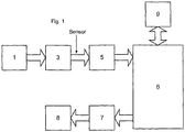
- FIG. 1 A schematic diagram of apparatus suitable for use in the present invention is shown in figure 1 .
- the nebuliser is, for preference, an ultrasonic nebuliser.
- the nebuliser 3 contains the liquid sterilisation agent, 35% hydrogen peroxide and is activated with the fan or shortly after the fan is turned on.
- the nebuliser generates droplets that are carried by the gas stream to create an aerosol which travels into the sterilisation chamber.
- the sterilant concentration in the aerosol stream can be adjusted by changing either the flow rate of the gas stream, the productivity of the nebuliser, or the concentration of the initial liquid sterilant that is nebulised.
- the passive waste removal vent or system 9 allows some gas flow to pass through it, equalising pressure and allowing the sterilisation chamber to remain at approximately room pressure.
- This passive system may typically include a pathway for flow to the outside air past catalytic elements that react with any sterilant and break the sterilant down into a safer chemistry suitable for disposal.
- the aerosol droplets contact the surface of the article to be sterilised, as well as the inner surface of the chamber.
- the small size of the droplets especially relative to their surface area, enables them to spread in a uniformly thin manner over the surface of the article, as well as access small areas, in some cases even mated surfaces.
- the fan 1 and the nebuliser 3 are deactivated and the air inlet valve 5 is closed.
- the exit valve 7 is opened and aerosol is removed with the active sterilant removal / waste system 8, which may include a pump that pulls aerosol and vapour out of the sterilisation chamber at a high rate.
- the gas flow removes unused aerosol from the chamber, and also removes aerosol from the surface of the article to be sterilised, and from the chamber walls.
- the fan 1 may also be used to assist in the aerosol removal phase. This has the advantage of removing any unused and/or condensed aerosol from the aerosol delivery pathway. If the aerosol delivery pathway is kept dry and free from any material, such as residual peroxide, the measuring of subsequent doses of aerosol can be made with more confidence.
- the removal system may include a pathway for flow between the sterilisation chamber and outside air past catalytic elements that react with the sterilant and break the sterilant down into a safer chemistry suitable for disposal.
- Passive vent 9 allows a source of fresh air to be drawn into the sterilisation chamber from the outside air.
- the switching of the various components of the apparatus is generally under software control, to ensure appropriate operation of the fan, nebuliser and valves in correct order, and to ensure that the timing is accurately controlled.
- the device may also incorporate flow sensors in line between the nebuliser and sterilising chamber and/or liquid level sensors in the nebuliser to measure when predetermined levels of sterilant have been administered to the chamber or used by the nebuliser.
- the surface of the sterilisation chamber may be electronically heated to a controlled temperature by thermostat means or otherwise, hence accelerating the speed of sterilisation (as is well known to those skilled in the art).
- an aerosol sensor is placed in fluid communication between the nebuliser 3 and the inlet valve 5 to the sterilisation chamber.
- the fan is activated, valve 5 is opened and the nebuliser remains deactivated. This causes a gas flow to pass by the sensor and into the chamber.
- the sensor gives a first reading which is influenced by the humidity, temperature and flow rate of the gas. Based on the value of this first reading, the software then selects a precalculated dosage calibration curve.
- the nebuliser 3 is then switched on, which generates the sterilant aerosol particles. These particles enter the airflow and then flow past the sensor and into the sterilisation chamber.
- the sensor is then read again to give a second reading which is influenced by the aerosol concentration, humidity, temperature and flow rate. This second reading is then input into the precalculated dosage calibration curve selected previously.
- the difference in readings reflects the aerosol density, ie how many grams of liquid are present per unit volume of aerosol.
- the deposition rate increases with both flow and aerosol density. For a given flow rate, the deposition rate is thus directly related to aerosol density (and vice versa, for a given aerosol density, the deposition rate is directly related to the flow rate).
- aerosol density references to "aerosol density” are intended to encompass the more rigorous definition of the "rate of deposition of droplets on the heated element".
- the precalculated dosage calibration curve may be devised by performing experiments where known and varying aerosol densities are placed in the presence of other controlled conditions such as varying air temperatures, humidities and flow rates.
- one sensor is placed between the fan 1 and the nebuliser 3, and another sensor is placed between the nebuliser 3 and the inlet valve 5 to the sterilisation chamber.
- the mass gas flow and mass aerosol in the gas flow readings can thus be made simultaneously, unlike the first method which requires the readings to be some time apart.
- the sensor preferred in the present invention is one based around the use of an element that consists of an electrical heating component and a temperature sensing component.
- the element is made up of a single component that can perform both functions, such as a RTD or a transistor.
- RTD resistive heater
- RTD's are well known for in relation to determine temperature, and operate on the principle that the resistance of metals, in particular platinum wire, is sensitive to the temperature at which the resistance is measured. In the case of a platinum wire RTD, a 1°C change in temperature corresponds to about 0.4 ⁇ change in resistance. Also, platinum wire has the desirable property that the response is relatively linear over a modest temperature range.
- RTD's typically have a thin metal film resistance that is silk screened or vacuum sputtered onto a ceramic substrate and an overlying glass passivation layer. These sensors are low in cost, robust, and importantly are unaffected by exposure to potentially destructive sterilants such as hydrogen peroxide.
- Resistance is measured by passing a current through the sensor and measuring the voltage drop across it.
- the RTD measurement current is typically kept small, to about 1ma or less, to avoid self-heating due to power dissipation in the sensor.
- the RTD is used in a very different fashion to that used for typical temperature measurement.
- RTD's can operate via a circuit not unlike a Wheatstone bridge, and a simplified circuit layout is shown in Figure 3 .
- Power source 10 puts out a flow of current into a circuit that can be completed by two competing resistive pathways.
- One resistive pathway, via R1 and R3 is of known resistance.
- the other resistive pathway comprises known resistance R2 and a variable resistance in the form of the platinum wire sensor 14.
- There is a voltage difference across the two pathways which reflects the relative resistance of each. This voltage difference is measured by potentiometer 15 (which is of sufficiently high resistance as to keep the resistive pathways above separate).
- potentiometer 15 which is of sufficiently high resistance as to keep the resistive pathways above separate.
- the voltage drop allows calculation of the resistance of the sensor 14, the only variable in the system.
- the resistance of sensor 14 is then correlated with its temperature.
- the circuit may be operated with sufficient power to heat sensor 14 (which is a platinum wire encased in a glass casing) to a suitable temperature to maintain an appropriate level of aerosol evaporation in a gas flow.
- Embodiments of the present invention may further include a feedback loop 16 between potentiometer 15 and power source 10, such that when the resistance of the sensor begins to decrease, the power output is increased to maintain a constant resistance. This enables the power source 10 to be operated in a manner such that a constant voltage difference across the balanced circuits is maintained, which consequently results in sensor 14 being maintained at a constant temperature.
- the amount of power required to maintain the sensor at a constant temperature i.e. the amount of power dissipation through the sensor wire reflects the total amount of cooling (gas flow plus evaporation) occurring on the sensor. The greater the cooling effect, the more power required.
- Power dissipation in the sensor is employed to achieve a degree of self heating of the sensor so that cooling effects can be measured.
- Measuring the density of nebulant in an aerosol flow at constant temperature has been found to be free of thermal runaway problems and produces a very fast sensor response, since temperature changes are momentary and small. Accordingly use of an RTD sensor at constant temperature is highly preferred, and the data herein shows that the method described with reference to Figure 3 produces reliable, reproducible and accurate data.
- RTD's could be used in other ways to determine aerosol density in a gas flow, for example, the device could be operated at a constant voltage, however this has been found to be relatively insensitive (compared to constant power) especially at low air speeds.
- the RTD may be used at constant current, however this has been found to involve a risk of overheating.
- the surface temperature of a sensor heated at a constant power could be measured by means of infra red radiation emitted by the surface.
- the aerosol sensors of the present invention can be used for the monitoring and control of sterilizers by using the feedback from the sensor in a variety of different ways. For example, if the sensor detects a drop in aerosol density, the relevant control system can increase aerosol flow rate, nebuliser output or both. Flow rate can be modified by changing the fan speed (or the voltage to the fan). Nebuliser output can be modified by controlling the electronic power provided to the nebuliser disc. It is generally preferable to maintain a constant gas flow and use the sensor to control nebuliser output in order to maintain aerosol density to within certain limits. By using the feedback from the sensor in these ways, the flow of a predetermined aerosol concentration past the mist sensor can be maintained for the duration of the aerosol delivery phase. The time of aerosol delivery can also be controlled. By applying a known density of aerosol for a known time, the delivery of a known dosage can be achieved.
- the amount of cooling reflects the amount of liquid in the droplets hitting the surface, and the flow rate of the carrier gas.
- the component of cooling caused by the flow of the carrier gas can be determined accurately by other means, and thus a baseline for this can be readily established.
- Baseline values for the cooling effect of the carrier gas can be established for a whole matrix of gases, flow rates, temperatures and humidities. For a known gas (eg air) at known (measured) temperature and humidity, the present apparatus can be used to determine the flow rate.
- an operating temperature can be chosen which is such that it allows rapid measurement of the mist density, by speeding the evaporation of condensed mist at such a rate that evaporation exceeds condensation. If the temperature is too low, the mist will soon begin to accumulate on the sensor, causing it to be come drenched in sterilant - as would be seen for any sort of unheated detector in an aerosol flow.
- the present invention thus enables both the density of the aerosol in the gas stream and the flow rate of the gas stream to be determined and consequently a dose of aerosol delivered by the gas stream can be precisely determined.
Landscapes
- Health & Medical Sciences (AREA)
- Life Sciences & Earth Sciences (AREA)
- General Health & Medical Sciences (AREA)
- Veterinary Medicine (AREA)
- Epidemiology (AREA)
- Animal Behavior & Ethology (AREA)
- Public Health (AREA)
- General Physics & Mathematics (AREA)
- Physics & Mathematics (AREA)
- Chemical & Material Sciences (AREA)
- Chemical Kinetics & Catalysis (AREA)
- General Chemical & Material Sciences (AREA)
- Analytical Chemistry (AREA)
- Biochemistry (AREA)
- Immunology (AREA)
- Pathology (AREA)
- Apparatus For Disinfection Or Sterilisation (AREA)
- Sampling And Sample Adjustment (AREA)
- Investigating Or Analyzing Materials Using Thermal Means (AREA)
Claims (15)
- Procédé destiné à mesurer la densité d'un aérosol stérilisant dans un flux de gaz pour les fins d'une mesure d'un dosage stérilisant, comprenant le passage d'un aérosol stérilisant suspendu dans un flux de gaz à taux d'écoulement au-delà d'un élément électriquement chauffé, caractérisé en ce que le procédé comprend la mesure d'un effet de refroidissement.
- Procédé selon la revendication 1, comprenant :i) le passage d'un flux de gaz à taux d'écoulement au-delà d'un élément électriquement chauffé et la mesure d'un premier effet de refroidissement :ii) le passage d'un aérosol suspendu dans un flux de gaz à taux d'écoulement au-delà d'un élément électriquement chauffé et la mesure d'un deuxième effet de refroidissement :iii) la mesure de la différence entre le premier effet de refroidissement et le deuxième effet de refroidissement et la corrélation de ladite différence avec la densité d'aérosol.
- Procédé selon la revendication 1, en outre utilisé pour la mesure d'un dosage d'un aérosol stérilisant, comprenant :1) la mesure de la densité d'un aérosol stérilisant dans un flux de gaz par :i) le passage d'un flux de gaz à taux d'écoulement au-delà d'un élément électriquement chauffé et la mesure d'un premier effet de refroidissement :ii) le passage d'un aérosol suspendu dans un flux de gaz à taux d'écoulement pour un temps de distribution d'aérosol au-delà d'un élément électriquement chauffé et la mesure d'un deuxième effet de refroidissement :iii) la mesure de la différence entre le premier effet de refroidissement et le deuxième effet de refroidissement et la corrélation de ladite différence avec la densité d'aérosol ; et2) l'application du temps de distribution d'aérosol et de la densité d'aérosol pour calculer une quantité distribuée d'aérosol.
- Procédé selon la revendication 3, comprenant en outre
3) l'arrêt de distribution supplémentaire d'aérosol stérilisant lorsque la quantité d'aérosol distribuée atteint un dosage prédéterminé ; pour ainsi fournir un dosage mesuré d'un aérosol stérilisant. - Procédé selon la revendication 1, en outre utilisé pour la stérilisation d'un article et la certification de celui comme stérile, par la mise en contact de l'article avec un aérosol stérilisant, et dans lequel le dosage d'aérosol stérilisant est mesuré par :1) la mesure de la densité d'un aérosol stérilisant dans un flux de gaz par :i) le passage d'un flux de gaz à taux d'écoulement au-delà d'un élément électriquement chauffé et la mesure d'un premier effet de refroidissement :ii) le passage d'un aérosol suspendu dans un flux de gaz à taux d'écoulement au-delà pour un temps de distribution d'aérosol au-delà d'un élément électriquement chauffé et la mesure d'un deuxième effet de refroidissement :iii) la mesure de la différence entre le premier effet de refroidissement et le deuxième effet de refroidissement et la corrélation de ladite différence avec la densité d'aérosol ; et2) l'application du taux d'écoulement, du temps de distribution d'aérosol, de la concentration d'aérosol et de la densité d'aérosol pour calculer une quantité distribuée d'aérosol.
- Procédé selon la revendication 5, comprenant en outre l'étape consistant à comparer le dosage distribué d'aérosol avec un dosage prédéterminé de certification, et la certification de l'article comme étant stérile si le dosage distribué est compris par, au niveau du ou supérieur au dosage prédéterminé de certification, ou le fait de ne pas certifier l'article comme étant stérile si le dosage distribué d'aérosol est inférieur au dosage prédéterminé de certification ou n'est pas compris par celui-ci.
- Procédé selon l'une quelconque des revendications précédentes, dans lequel l'aérosol stérilisant est un aérosol du peroxyde d'hydrogène aqueux et le gaz est l'air.
- Procédé selon l'une quelconque des revendications précédentes, dans lequel la température de l'élément chauffé est supérieure ou égale au point de vaporisation dudit aérosol.
- Procédé selon l'une quelconque des revendications précédentes, dans lequel l'élément chauffé est couplé à un élément sensible à la température qui mesure la température dudit élément chauffé.
- Procédé selon la revendication 9, dans lequel ledit effet de refroidissement est mesuré par l'application dudit élément sensible à la température dans un système de commande à boucle de contre-réaction pour maintenir électriquement ledit élément chauffé à une température préréglée, dans lequel ledit effet de refroidissement est mesuré par l'effort de chauffage nécessaire, ou une partie de celui-ci, pour maintenir ladite température préréglée, ou dans lequel ledit effet de refroidissement est mesuré par l'application dudit élément sensible à la température pour mesurer la température dudit élément chauffé, dans lequel ledit effet de refroidissement est mesuré par la mesure de la température dudit élément chauffé.
- Procédé selon la revendication 9 ou 10, dans lequel ledit élément chauffé et ledit élément sensible à la température est un seul et même élément.
- Procédé selon l'une quelconque des revendications 9 à 11 dans lequel ledit élément chauffé et ledit élément sensible à la température est un RTD, notamment un RTD du type film plat ; ou est un transistor.
- Procédé selon l'une quelconque des revendications précédentes, comprenant en outre l'étape de mesure du taux d'écoulement de flux de gaz par une comparaison de l'effet de refroidissement sur le capteur du flux de gaz avec des valeurs prédéterminées pour l'effet de refroidissement de taux d'écoulement de gaz.
- Procédé selon la revendication 1, en outre utilisé pour maintenir un flux constant d'un aérosol, comprenant :1) la mesure de la densité d'un aérosol dans un flux de gaz par :i) le passage d'un flux de gaz à taux d'écoulement au-delà d'un élément électriquement chauffé et la mesure d'un premier effet de refroidissement :ii) le passage d'un aérosol suspendu dans un flux de gaz à taux d'écoulement pour un temps de distribution d'aérosol au-delà d'un élément électriquement chauffé et la mesure d'un deuxième effet de refroidissement :iii) la mesure de la différence entre le premier effet de refroidissement et le deuxième effet de refroidissement et la corrélation de ladite différence avec la densité d'aérosol ;2) le maintien du deuxième effet constant de refroidissement à un constant ou une valeur prédéterminée.
- Procédé selon la revendication 14, comprenant en outre :
2) le maintien du deuxième effet constant de refroidissement pendant une période de temps prédéterminée à une valeur prédéterminée; pour ainsi fournir un dosage connu d'un aérosol.
Applications Claiming Priority (2)
| Application Number | Priority Date | Filing Date | Title |
|---|---|---|---|
| AU2008903352A AU2008903352A0 (en) | 2008-06-30 | Aerosol sensor | |
| PCT/AU2009/000841 WO2010000021A1 (fr) | 2008-06-30 | 2009-06-30 | Capteur d'aérosol |
Publications (3)
| Publication Number | Publication Date |
|---|---|
| EP2313752A1 EP2313752A1 (fr) | 2011-04-27 |
| EP2313752A4 EP2313752A4 (fr) | 2017-11-08 |
| EP2313752B1 true EP2313752B1 (fr) | 2018-11-21 |
Family
ID=41465407
Family Applications (1)
| Application Number | Title | Priority Date | Filing Date |
|---|---|---|---|
| EP09771838.1A Active EP2313752B1 (fr) | 2008-06-30 | 2009-06-30 | Capteur d'aérosol |
Country Status (9)
| Country | Link |
|---|---|
| US (1) | US9027385B2 (fr) |
| EP (1) | EP2313752B1 (fr) |
| JP (1) | JP5536768B2 (fr) |
| KR (1) | KR20110044856A (fr) |
| CN (1) | CN102084231B (fr) |
| AU (1) | AU2009266410B2 (fr) |
| CA (1) | CA2729603C (fr) |
| EA (1) | EA020894B1 (fr) |
| WO (1) | WO2010000021A1 (fr) |
Families Citing this family (7)
| Publication number | Priority date | Publication date | Assignee | Title |
|---|---|---|---|---|
| USRE47582E1 (en) | 2009-07-28 | 2019-08-27 | Sterifre Medical, Inc. | Free radical sterilization system and method |
| US8741228B2 (en) * | 2011-09-23 | 2014-06-03 | American Sterilizer Company | Hydrogen peroxide vaporizer with heated diffuser |
| KR101520384B1 (ko) * | 2013-08-09 | 2015-05-22 | 계명대학교 산학협력단 | 분포형 열전대 온도센서 및 이를 사용하는 열전대 기반 분포형 온도측정 시스템 |
| EP3471782A1 (fr) | 2016-06-17 | 2019-04-24 | Sterifre Medical Inc. | Dispositifs thérapeutiques, systèmes et procédés pour la stérilisation, la désinfection, le nettoyage et la décontamination |
| DE202016107242U1 (de) * | 2016-12-21 | 2018-03-22 | Nordson Corp. | Sensoreinrichtung zur Bestimmung eines Massenstroms eines flüssigen Heißschmelzklebstoffes |
| US11344643B2 (en) | 2017-10-25 | 2022-05-31 | Sterifre Medical, Inc. | Devices, systems, and methods for sterilization, disinfection, sanitization and decontamination |
| US11565059B2 (en) * | 2018-02-27 | 2023-01-31 | Juul Labs, Inc. | Mass output controlled vaporizer |
Family Cites Families (25)
| Publication number | Priority date | Publication date | Assignee | Title |
|---|---|---|---|---|
| US3579097A (en) * | 1969-12-30 | 1971-05-18 | Of Engraving Inc Bureau | Apparatus and method for measuring the amount of a selected vapor in an atmosphere |
| US4305724A (en) * | 1980-08-04 | 1981-12-15 | Delphian Partners | Combustible gas detection system |
| US4512951A (en) * | 1980-12-30 | 1985-04-23 | American Sterilizer Company | Hydrogen peroxide liquid film sterilization method |
| JPH0692929B2 (ja) * | 1991-03-26 | 1994-11-16 | 工業技術院長 | 気中微小粒子特性測定装置 |
| US5789258A (en) * | 1991-06-10 | 1998-08-04 | Midwest Research Institute | Method for generating vapor streams |
| JP2686878B2 (ja) * | 1992-06-02 | 1997-12-08 | 山武ハネウエル株式会社 | 複合センサ装置 |
| JP3065862B2 (ja) * | 1992-10-27 | 2000-07-17 | 株式会社半導体エネルギー研究所 | 流量検出装置および流量検出方法 |
| US5371469A (en) * | 1993-02-16 | 1994-12-06 | The United States Of America As Represented By The Administrator Of The National Aeronautics And Space Administration | Constant current loop impedance measuring system that is immune to the effects of parasitic impedances |
| US5600142A (en) * | 1995-05-26 | 1997-02-04 | Uop | Measurement of vaporized hydrogen peroxide |
| US6325972B1 (en) * | 1998-12-30 | 2001-12-04 | Ethicon, Inc. | Apparatus and process for concentrating a liquid sterilant and sterilizing articles therewith |
| US6071476A (en) * | 1997-11-14 | 2000-06-06 | Motorola, Inc. | Exhaust gas sensor |
| US5989398A (en) * | 1997-11-14 | 1999-11-23 | Motorola, Inc. | Calorimetric hydrocarbon gas sensor |
| US6318151B1 (en) * | 1999-07-26 | 2001-11-20 | Abbott Laboratories | Self-contained sterilant monitoring assembly and method of using same |
| JP2004536301A (ja) * | 2001-07-16 | 2004-12-02 | センサー テック インコーポレイテッド | 気相物質の定性および定量分析のためのセンサ装置および方法 |
| US20030124026A1 (en) * | 2001-11-05 | 2003-07-03 | Hal Williams | Apparatus and process for concentrating a sterilant and sterilizing articles therewith |
| US6916664B2 (en) * | 2002-06-14 | 2005-07-12 | Honeywell International Inc. | Flammable vapor sensor |
| JP2005098846A (ja) * | 2003-09-25 | 2005-04-14 | Tdk Corp | ガスセンサ |
| US8668873B2 (en) * | 2005-02-02 | 2014-03-11 | The Florida International University Board Of Trustees | Method and apparatus for extraction, detection, and characterization of vapors from explosives, taggants in explosives, controlled substances, and biohazards |
| US7592178B2 (en) * | 2005-02-23 | 2009-09-22 | Hunter Menufacturing Co. | Filter integrity tester |
| BRPI0614461A2 (pt) * | 2005-08-04 | 2012-11-27 | Saban Ventures Pty Ltd | método para desinfetar ou esterilizar um artigo, ou parte do artigo |
| US7871016B2 (en) * | 2005-08-26 | 2011-01-18 | Altapure, Llc | Method and apparatus for an improved aerosol generator and associated uses and equipment |
| US7430928B2 (en) * | 2006-02-08 | 2008-10-07 | Battelle Memorial Insititute | Method and apparatus for concentrating vapors for analysis |
| US20090007636A1 (en) * | 2007-07-02 | 2009-01-08 | Therm-O-Disc, Incorporated | Chemiresistor Sensor System Compensated for Temperature and Aging Effects |
| US8178357B2 (en) * | 2007-07-26 | 2012-05-15 | The Regents Of The University Of California | Peroxide chemical sensor and sensing method |
| CN103826756B (zh) * | 2011-09-19 | 2017-03-01 | 皇家飞利浦有限公司 | 气雾剂输出的分析和控制 |
-
2009
- 2009-06-30 EA EA201170105A patent/EA020894B1/ru unknown
- 2009-06-30 US US13/002,003 patent/US9027385B2/en active Active
- 2009-06-30 WO PCT/AU2009/000841 patent/WO2010000021A1/fr active Application Filing
- 2009-06-30 JP JP2011515022A patent/JP5536768B2/ja active Active
- 2009-06-30 EP EP09771838.1A patent/EP2313752B1/fr active Active
- 2009-06-30 AU AU2009266410A patent/AU2009266410B2/en active Active
- 2009-06-30 CA CA2729603A patent/CA2729603C/fr active Active
- 2009-06-30 KR KR1020117002346A patent/KR20110044856A/ko not_active Application Discontinuation
- 2009-06-30 CN CN2009801260836A patent/CN102084231B/zh active Active
Non-Patent Citations (1)
| Title |
|---|
| None * |
Also Published As
| Publication number | Publication date |
|---|---|
| CA2729603C (fr) | 2019-04-30 |
| EP2313752A4 (fr) | 2017-11-08 |
| EA201170105A1 (ru) | 2011-08-30 |
| US9027385B2 (en) | 2015-05-12 |
| AU2009266410A1 (en) | 2010-01-07 |
| JP5536768B2 (ja) | 2014-07-02 |
| US20110167895A1 (en) | 2011-07-14 |
| EP2313752A1 (fr) | 2011-04-27 |
| JP2011526160A (ja) | 2011-10-06 |
| AU2009266410B2 (en) | 2014-05-08 |
| CA2729603A1 (fr) | 2010-01-07 |
| EA020894B1 (ru) | 2015-02-27 |
| CN102084231B (zh) | 2013-12-04 |
| KR20110044856A (ko) | 2011-05-02 |
| WO2010000021A1 (fr) | 2010-01-07 |
| CN102084231A (zh) | 2011-06-01 |
Similar Documents
| Publication | Publication Date | Title |
|---|---|---|
| EP2313752B1 (fr) | Capteur d'aérosol | |
| US7858026B2 (en) | Detection of sterilisation vapour condensation point | |
| DK2485772T3 (en) | Sterilization devices and method for control of a sterilization devices | |
| EP2150279B1 (fr) | Appareil de calibrage de sonde de peroxyde d'hydrogène vaporisé | |
| EP0774263A1 (fr) | Procédé et appareil pour la stérilisation par la vapeur de peroxyde d'hydrogène | |
| CA2532819C (fr) | Capteur permettant de determiner la concentration d'un sterilisant fluide | |
| US20190224356A1 (en) | Apparatus and method for sterilizing endoscope | |
| KR20060037355A (ko) | 살균제의 농도를 결정하는 시스템 및 방법 | |
| WO2002072160A1 (fr) | Dosimetre de routine faisant appel a la calorimetrie, utilise dans une installation de traitement par faisceau d'electrons | |
| US20230398251A1 (en) | Apparatus And Method For Sterilizing Endoscope | |
| Haller et al. | Adverse impact of temperature and humidity on blood glucose monitoring reliability: a pilot study | |
| JP6573987B2 (ja) | 気中微粒子計測器及び清浄環境機器 | |
| AU2021270309B2 (en) | Method and apparatus for decontaminating articles in a steam sterilizer at low temperature | |
| JP2010115451A (ja) | 除染装置、該除染装置における除染条件の決定方法、及び該除染装置における除染条件の管理方法。 | |
| JP2006125981A (ja) | 分析装置 | |
| Tessarolo et al. | Monitoring Steam Penetration in Channeled Instruments: An Evidence-Based Worst-Case for Practical Situations | |
| Russell et al. | Sterilisation Methods | |
| Rickloff | Hydrogen peroxide gas decontamination | |
| Cardoso et al. | HMC Europe HG-80 autoclave qualification for its use with solid materials at the sancti spiritus (Cuba)-faculty of medicine vaccination center | |
| Watling | Isolation technology: hydrogen peroxide decontamination | |
| Prins et al. | Sterilisation Methods | |
| Agalloco | Innovation in Biological Indicator Evaluator Resistometer Vessel Technology | |
| Ruiz Vargas | Development of Vaporized Hydrogen Peroxide (VHP) Decontamination Cycle for a Syringe Isolator |
Legal Events
| Date | Code | Title | Description |
|---|---|---|---|
| PUAI | Public reference made under article 153(3) epc to a published international application that has entered the european phase |
Free format text: ORIGINAL CODE: 0009012 |
|
| 17P | Request for examination filed |
Effective date: 20110127 |
|
| AK | Designated contracting states |
Kind code of ref document: A1 Designated state(s): AT BE BG CH CY CZ DE DK EE ES FI FR GB GR HR HU IE IS IT LI LT LU LV MC MK MT NL NO PL PT RO SE SI SK TR |
|
| AX | Request for extension of the european patent |
Extension state: AL BA RS |
|
| DAX | Request for extension of the european patent (deleted) | ||
| RA4 | Supplementary search report drawn up and despatched (corrected) |
Effective date: 20171011 |
|
| RIC1 | Information provided on ipc code assigned before grant |
Ipc: G01K 7/16 20060101ALI20171005BHEP Ipc: A61L 2/20 20060101ALI20171005BHEP Ipc: G01K 13/02 20060101AFI20171005BHEP |
|
| GRAP | Despatch of communication of intention to grant a patent |
Free format text: ORIGINAL CODE: EPIDOSNIGR1 |
|
| STAA | Information on the status of an ep patent application or granted ep patent |
Free format text: STATUS: GRANT OF PATENT IS INTENDED |
|
| INTG | Intention to grant announced |
Effective date: 20180607 |
|
| GRAS | Grant fee paid |
Free format text: ORIGINAL CODE: EPIDOSNIGR3 |
|
| GRAA | (expected) grant |
Free format text: ORIGINAL CODE: 0009210 |
|
| STAA | Information on the status of an ep patent application or granted ep patent |
Free format text: STATUS: THE PATENT HAS BEEN GRANTED |
|
| AK | Designated contracting states |
Kind code of ref document: B1 Designated state(s): AT BE BG CH CY CZ DE DK EE ES FI FR GB GR HR HU IE IS IT LI LT LU LV MC MK MT NL NO PL PT RO SE SI SK TR |
|
| REG | Reference to a national code |
Ref country code: CH Ref legal event code: EP |
|
| REG | Reference to a national code |
Ref country code: IE Ref legal event code: FG4D |
|
| REG | Reference to a national code |
Ref country code: DE Ref legal event code: R096 Ref document number: 602009055802 Country of ref document: DE |
|
| REG | Reference to a national code |
Ref country code: AT Ref legal event code: REF Ref document number: 1068094 Country of ref document: AT Kind code of ref document: T Effective date: 20181215 |
|
| REG | Reference to a national code |
Ref country code: NL Ref legal event code: MP Effective date: 20181121 |
|
| REG | Reference to a national code |
Ref country code: AT Ref legal event code: MK05 Ref document number: 1068094 Country of ref document: AT Kind code of ref document: T Effective date: 20181121 |
|
| PG25 | Lapsed in a contracting state [announced via postgrant information from national office to epo] |
Ref country code: AT Free format text: LAPSE BECAUSE OF FAILURE TO SUBMIT A TRANSLATION OF THE DESCRIPTION OR TO PAY THE FEE WITHIN THE PRESCRIBED TIME-LIMIT Effective date: 20181121 Ref country code: LV Free format text: LAPSE BECAUSE OF FAILURE TO SUBMIT A TRANSLATION OF THE DESCRIPTION OR TO PAY THE FEE WITHIN THE PRESCRIBED TIME-LIMIT Effective date: 20181121 Ref country code: ES Free format text: LAPSE BECAUSE OF FAILURE TO SUBMIT A TRANSLATION OF THE DESCRIPTION OR TO PAY THE FEE WITHIN THE PRESCRIBED TIME-LIMIT Effective date: 20181121 Ref country code: LT Free format text: LAPSE BECAUSE OF FAILURE TO SUBMIT A TRANSLATION OF THE DESCRIPTION OR TO PAY THE FEE WITHIN THE PRESCRIBED TIME-LIMIT Effective date: 20181121 Ref country code: NO Free format text: LAPSE BECAUSE OF FAILURE TO SUBMIT A TRANSLATION OF THE DESCRIPTION OR TO PAY THE FEE WITHIN THE PRESCRIBED TIME-LIMIT Effective date: 20190221 Ref country code: IS Free format text: LAPSE BECAUSE OF FAILURE TO SUBMIT A TRANSLATION OF THE DESCRIPTION OR TO PAY THE FEE WITHIN THE PRESCRIBED TIME-LIMIT Effective date: 20190321 Ref country code: FI Free format text: LAPSE BECAUSE OF FAILURE TO SUBMIT A TRANSLATION OF THE DESCRIPTION OR TO PAY THE FEE WITHIN THE PRESCRIBED TIME-LIMIT Effective date: 20181121 Ref country code: BG Free format text: LAPSE BECAUSE OF FAILURE TO SUBMIT A TRANSLATION OF THE DESCRIPTION OR TO PAY THE FEE WITHIN THE PRESCRIBED TIME-LIMIT Effective date: 20190221 Ref country code: HR Free format text: LAPSE BECAUSE OF FAILURE TO SUBMIT A TRANSLATION OF THE DESCRIPTION OR TO PAY THE FEE WITHIN THE PRESCRIBED TIME-LIMIT Effective date: 20181121 |
|
| PG25 | Lapsed in a contracting state [announced via postgrant information from national office to epo] |
Ref country code: GR Free format text: LAPSE BECAUSE OF FAILURE TO SUBMIT A TRANSLATION OF THE DESCRIPTION OR TO PAY THE FEE WITHIN THE PRESCRIBED TIME-LIMIT Effective date: 20190222 Ref country code: SE Free format text: LAPSE BECAUSE OF FAILURE TO SUBMIT A TRANSLATION OF THE DESCRIPTION OR TO PAY THE FEE WITHIN THE PRESCRIBED TIME-LIMIT Effective date: 20181121 Ref country code: PT Free format text: LAPSE BECAUSE OF FAILURE TO SUBMIT A TRANSLATION OF THE DESCRIPTION OR TO PAY THE FEE WITHIN THE PRESCRIBED TIME-LIMIT Effective date: 20190321 Ref country code: NL Free format text: LAPSE BECAUSE OF FAILURE TO SUBMIT A TRANSLATION OF THE DESCRIPTION OR TO PAY THE FEE WITHIN THE PRESCRIBED TIME-LIMIT Effective date: 20181121 |
|
| PG25 | Lapsed in a contracting state [announced via postgrant information from national office to epo] |
Ref country code: DK Free format text: LAPSE BECAUSE OF FAILURE TO SUBMIT A TRANSLATION OF THE DESCRIPTION OR TO PAY THE FEE WITHIN THE PRESCRIBED TIME-LIMIT Effective date: 20181121 Ref country code: PL Free format text: LAPSE BECAUSE OF FAILURE TO SUBMIT A TRANSLATION OF THE DESCRIPTION OR TO PAY THE FEE WITHIN THE PRESCRIBED TIME-LIMIT Effective date: 20181121 Ref country code: CZ Free format text: LAPSE BECAUSE OF FAILURE TO SUBMIT A TRANSLATION OF THE DESCRIPTION OR TO PAY THE FEE WITHIN THE PRESCRIBED TIME-LIMIT Effective date: 20181121 Ref country code: IT Free format text: LAPSE BECAUSE OF FAILURE TO SUBMIT A TRANSLATION OF THE DESCRIPTION OR TO PAY THE FEE WITHIN THE PRESCRIBED TIME-LIMIT Effective date: 20181121 |
|
| REG | Reference to a national code |
Ref country code: DE Ref legal event code: R097 Ref document number: 602009055802 Country of ref document: DE |
|
| PG25 | Lapsed in a contracting state [announced via postgrant information from national office to epo] |
Ref country code: RO Free format text: LAPSE BECAUSE OF FAILURE TO SUBMIT A TRANSLATION OF THE DESCRIPTION OR TO PAY THE FEE WITHIN THE PRESCRIBED TIME-LIMIT Effective date: 20181121 Ref country code: EE Free format text: LAPSE BECAUSE OF FAILURE TO SUBMIT A TRANSLATION OF THE DESCRIPTION OR TO PAY THE FEE WITHIN THE PRESCRIBED TIME-LIMIT Effective date: 20181121 Ref country code: SK Free format text: LAPSE BECAUSE OF FAILURE TO SUBMIT A TRANSLATION OF THE DESCRIPTION OR TO PAY THE FEE WITHIN THE PRESCRIBED TIME-LIMIT Effective date: 20181121 |
|
| PLBE | No opposition filed within time limit |
Free format text: ORIGINAL CODE: 0009261 |
|
| STAA | Information on the status of an ep patent application or granted ep patent |
Free format text: STATUS: NO OPPOSITION FILED WITHIN TIME LIMIT |
|
| 26N | No opposition filed |
Effective date: 20190822 |
|
| PG25 | Lapsed in a contracting state [announced via postgrant information from national office to epo] |
Ref country code: SI Free format text: LAPSE BECAUSE OF FAILURE TO SUBMIT A TRANSLATION OF THE DESCRIPTION OR TO PAY THE FEE WITHIN THE PRESCRIBED TIME-LIMIT Effective date: 20181121 |
|
| PG25 | Lapsed in a contracting state [announced via postgrant information from national office to epo] |
Ref country code: MC Free format text: LAPSE BECAUSE OF FAILURE TO SUBMIT A TRANSLATION OF THE DESCRIPTION OR TO PAY THE FEE WITHIN THE PRESCRIBED TIME-LIMIT Effective date: 20181121 |
|
| REG | Reference to a national code |
Ref country code: CH Ref legal event code: PL |
|
| REG | Reference to a national code |
Ref country code: BE Ref legal event code: MM Effective date: 20190630 |
|
| PG25 | Lapsed in a contracting state [announced via postgrant information from national office to epo] |
Ref country code: TR Free format text: LAPSE BECAUSE OF FAILURE TO SUBMIT A TRANSLATION OF THE DESCRIPTION OR TO PAY THE FEE WITHIN THE PRESCRIBED TIME-LIMIT Effective date: 20181121 |
|
| PG25 | Lapsed in a contracting state [announced via postgrant information from national office to epo] |
Ref country code: IE Free format text: LAPSE BECAUSE OF NON-PAYMENT OF DUE FEES Effective date: 20190630 |
|
| PG25 | Lapsed in a contracting state [announced via postgrant information from national office to epo] |
Ref country code: CH Free format text: LAPSE BECAUSE OF NON-PAYMENT OF DUE FEES Effective date: 20190630 Ref country code: LI Free format text: LAPSE BECAUSE OF NON-PAYMENT OF DUE FEES Effective date: 20190630 Ref country code: BE Free format text: LAPSE BECAUSE OF NON-PAYMENT OF DUE FEES Effective date: 20190630 Ref country code: LU Free format text: LAPSE BECAUSE OF NON-PAYMENT OF DUE FEES Effective date: 20190630 |
|
| PG25 | Lapsed in a contracting state [announced via postgrant information from national office to epo] |
Ref country code: CY Free format text: LAPSE BECAUSE OF FAILURE TO SUBMIT A TRANSLATION OF THE DESCRIPTION OR TO PAY THE FEE WITHIN THE PRESCRIBED TIME-LIMIT Effective date: 20181121 |
|
| PG25 | Lapsed in a contracting state [announced via postgrant information from national office to epo] |
Ref country code: MT Free format text: LAPSE BECAUSE OF FAILURE TO SUBMIT A TRANSLATION OF THE DESCRIPTION OR TO PAY THE FEE WITHIN THE PRESCRIBED TIME-LIMIT Effective date: 20181121 Ref country code: HU Free format text: LAPSE BECAUSE OF FAILURE TO SUBMIT A TRANSLATION OF THE DESCRIPTION OR TO PAY THE FEE WITHIN THE PRESCRIBED TIME-LIMIT; INVALID AB INITIO Effective date: 20090630 |
|
| REG | Reference to a national code |
Ref country code: DE Ref legal event code: R082 Ref document number: 602009055802 Country of ref document: DE Representative=s name: ZACCO LEGAL RECHTSANWALTSGESELLSCHAFT MBH, DE |
|
| PG25 | Lapsed in a contracting state [announced via postgrant information from national office to epo] |
Ref country code: MK Free format text: LAPSE BECAUSE OF FAILURE TO SUBMIT A TRANSLATION OF THE DESCRIPTION OR TO PAY THE FEE WITHIN THE PRESCRIBED TIME-LIMIT Effective date: 20181121 |
|
| P01 | Opt-out of the competence of the unified patent court (upc) registered |
Effective date: 20230526 |
|
| PGFP | Annual fee paid to national office [announced via postgrant information from national office to epo] |
Ref country code: GB Payment date: 20240530 Year of fee payment: 16 |
|
| PGFP | Annual fee paid to national office [announced via postgrant information from national office to epo] |
Ref country code: DE Payment date: 20240617 Year of fee payment: 16 |
|
| PGFP | Annual fee paid to national office [announced via postgrant information from national office to epo] |
Ref country code: FR Payment date: 20240621 Year of fee payment: 16 |